

OPERATING INSTRUCTIONS
PROMOVET sarl
ZAC de la Route de Beauraing, 1
08600 GIVET (France)
info @ promovet.fr
DROPER FIELD 1000
FULLY MECHANICAL INFUSION PUMP
1 / 16

Table of contents
1 Description of the Droper Field 1000 3
2 Using the Droper Field 1000 4
3 Operating issues 11
4 End of infusion 12
5 Cleaning / Disinfection 13
6 Periodic inspection 15
7 Storage 15
8 Warranty conditions 15
9 Life 16
10 Useful contacts 16
2 / 16
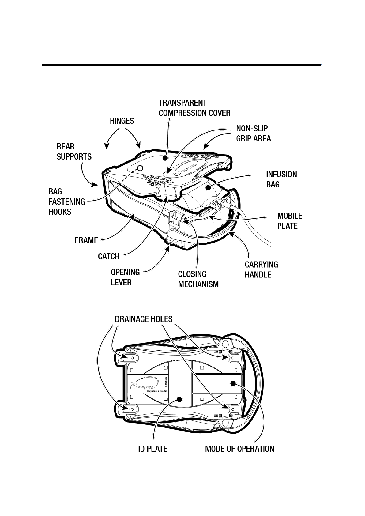
1. DESCRIPTION OF THE DROPER
3 / 16
2. USING THE DROPER FIELD 1000
The Droper Field is a medical device designed to pressurise flexible infusion bags containing all
solutions suitable for intravenous infusion for the administration, in a non-intrusive manner by
infusion, of the contained solutions to patients requiring the latter. The device is dimensioned in such
a way as to be able to receive most infusion bags up to 1,000 ml commercially available at the time of
its introduction, in order to produce a bag pressure of about 100 mbar, equivalent to an approximate
height of 1 metre between the patient and the infusion bag for administration by gravity.
The safety instructions regarding the use of such bags must be known prior to use.
Its transparent cover enables the user to see the nature of the substance
administered. Principally intended for use in emergency situations or
catastrophes where stress levels are high, the device must be used by
trained, qualified staff.
The Droper Field device is not sensitive to environmental conditions. It has
been designed using materials capable of operating at both negative and
positive temperatures.
The infusion flow rate is entirely dependent on the viscosity of the infusion
solution. In cases not using a drip chamber (see below), different types of
flow regulators are commercially available for different viscosities and for
pressures equivalent to that generated by the Droper Field 1000. The
operator must therefore take this into account when choosing the flow
regulator to be used in these cases.
Under no circumstances may rigid or semi-rigid bottles be inserted into
the device.
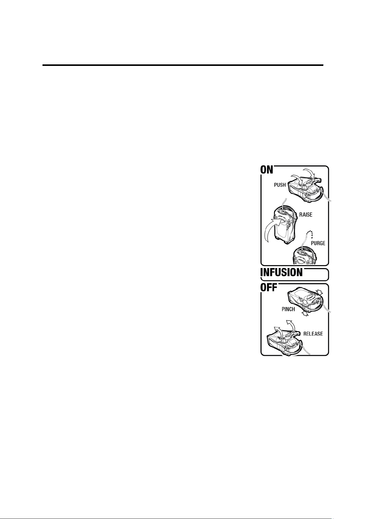
The device's method of operation is described hereinbelow in the form of
several pictograms, which can be found underneath the device and shown
opposite:
2.1 Opening the cover
The mobile plate located underneath the transparent cover has certain elastic properties when
pressure is exerted in a downwards direction. To open the Droper Field 1000, the device is placed on
a flat, stable surface directly beneath the operator. The operator grasps the Droper Field 1000 by
placing the cushion of his/her thumbs on the non-slip areas provided for this purpose on either side of
the cover.
4 / 16
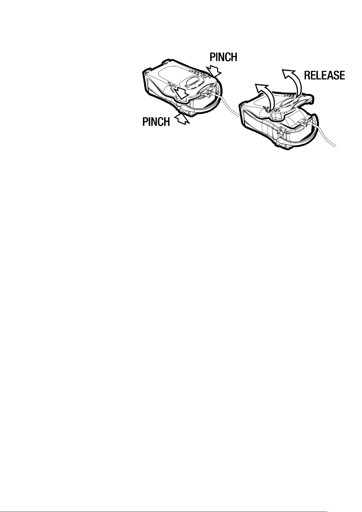
With outstretched arms, the operator places his/her middle finger
of each hand underneath the disarming side lever. The device opens
in three steps:
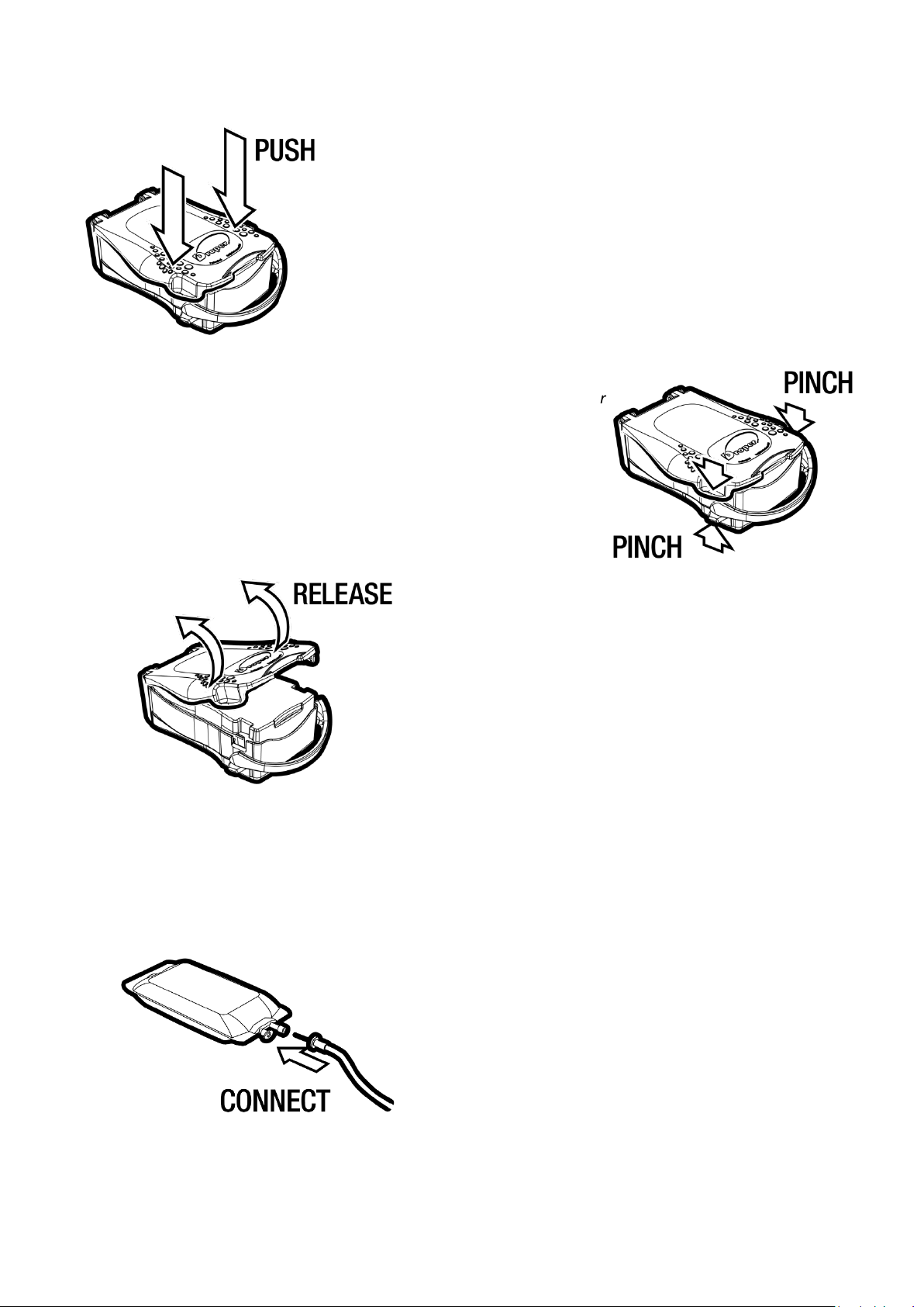
1. The operator firstly exerts pressure in a downwards direction on
the cover using his/her body weight and with outstretched arms.
This action places pressure on the mobile plate. The resulting
small downwards movement can be observed.
2. Without releasing the pressure exerted on the cover, the operator
then exerts upwards pressure on the two disarming side levers
by pinching his/her middle fingers of each hand upwards and
inwards. This movement will result in pivoting the closing spring
clips inwards and releasing the cover.
2.2 Inserting the infusion line
3. While holding the two open levers in position, release
the pressure exerted on the cover. Then open the
cover by pushing it upwards using an index finger.
Where necessary, install an extension with a 3-way
stopcock at the start of the line to be able to check the
correct operation of the device during the infusion.
Check that the choke or flow regulator is set to the OFF
position.
Check that the air intake valve in the drip chamber is in
the closed position.
Insert the piercing pin at the bottom into the tubing port
of the infusion bag.
5 / 16

2.3 Choosing the infusion line
Different types of infusion lines may be used. Their choice and handling with regard to air drainage are
determined according to the Droper's mode of use.
1. Infusion line with drip chamber positioned in the middle of the infusion line (not with drip
chamber connected directly to the spike).
a. Residential infusion (Home care, Hospital, Field
hospital, …) with drip chamber positioned upright,
liquid output in a downwards direction (classic
example): as for gravitational infusions, the drip
chamber is filled with the perfusion fluid until a
certain height is reached, with air being
positioned at the top of the drip chamber. The
flow will be estimated by counting the number of
drops in the first minute of infusion.
b. Infusions in hostile environments with drip chambers capable of being positioned lying
down, or upright with liquid output in a upwards direction during transfer under
infusion: in this case there is a risk that air bubbles originating from the free air
enclosed in the drip chamber are infused. The operator must therefore use the reverse
purge air drainage technique expelling all air including that contained in the drip
chamber. The drip chamber will no longer be used as a reference to estimate the flow
of solution infused. This flow must be estimated or checked using a suitable flow
regulator.
6 / 16

2. Infusion line without drip chamber: the operator must therefore use the reverse purge air
drainage technique expelling all air including that contained in the infusion bag and in the
infusion line. If there is no drip chamber, the infused flow must be estimated or checked by
means of a suitable flow regulator.
2.4 Inserting the infusion bag with the infusion
line and closing the device
1. Insertion: With the cover fully open, position the
infusion bag on the plate and attach it to one of the fastening
hooks on the plate.
The purpose of these fasteners is to prevent the bag from
sliding forwards when closing the device. Two fasteners are
available according to the model of bag used. Their location is
designed to suit the main infusion bag models available on the
market.
If the fastener does not correspond to the bag model used,
the operator must maintain pressure on this bag in a backwards direction to prevent it from sliding
forwards when closing the device.
2. To close: pivot the cover forwards until it enters
into contact with the bulge at the surface of the infusion bag.
Stand directly above the device with outstretched arms and
press down on the cover, placing the cushions of each thumb
on the rough areas located on either side of the cover.
A force of approximately 36 kg is required to pressurise the
device. Prior training is thus recommended to master how to
operate the device.
WARNING: once the movement has been initiated (once the initial resistance has been broken), the
pivoting movement applied to the cover will become easier and the force exerted must be reduced.
This action places pressure on the mobile plate. The resulting significant downwards movement can
be observed. The system closes and is therefore armed as soon as the closing clicks are heard. After
releasing the pressure, the operator must check that the two fastening hooks visible through the
transparent cover are engaged.
If engagement can only be observed on one side, the plate will adopt an inclined position in relation
to the device. In this event, push back down on the cover to release the engaged hook and repeat the
closing operation. This operation pressurises the infusion bag.
7 / 16

2.5 Draining the infusion line and bag
Two reverse purge air drainage scenarios are possible:
1. Draining an infusion bag outside of the Droper by exerting upwards hand pressure on the bag held
upright and perforated with the infusion line.
a. Case where the drip chamber may be used in the
upright position (case 2.3 1-a described above): with the
clamp closed, expel all air contained in the infusion bag until
the drip chamber becomes filled with part of the liquid.
Then insert the bag into the Droper Field as described in
point 2.4 above, ensuring that the drip chamber is
positioned with the outlet pointing downwards. Close the
Droper Field, open the clamp and the Luer Lock cap located
at the end of the line and expel the residual air in the
infusion line.
b. Case where the drip chamber cannot be used upright (case 2.3 1-b described above) and
case where the line does not have a drip chamber: with both the clamp and Luer Lock cap
at the end of the line open, expel all air contained in the infusion bag until the drip chamber
is entirely filled with the infusion solution. Close the choke. Position the bag in the Droper
Field as described in point 2.4 above. Close the Droper Field, re-open the choke and drain
all residual air from the infusion line.
8 / 16

2. Draining an infusion bag installed in the Droper Field using the pressure
generated by the latter. To achieve this, position the Droper Field
upright on its two rear supports. Begin to expel the air as described
above in point 1.a and 1.b according to the type of line and whether a
drip chamber is used.
Connect the infusion line to the patient as per the operating
instructions specific to the infusion line. Check the free
tubing of the infusion line and the absence of any
folds. Adjust to the desired flow rate using the roller
clamp (case 2.3 1-a) or a suitable flow regulator
(case 2.3 1-b and 2.3 2) and begin the infusion.
Ideally, the device should be positioned level with the patient's midaxillary line
to guarantee an approximate pressure of 100 mbar.
If placed at a higher level, and according to the atmospheric pressure conditions, the pressure shall be
approximately increased (in mbar) by the distance (in cm) separating this line from the device outlet
and conversely if it is placed at a lower level. In any event, this position must be taken into account
when adjusting the flow rate.
The Droper Field 1000 is designed for use in
emergency situations and in hostile
environments and does not provide for the electronic
or electrical monitoring of the infusion. The infusion
stage may be assessed by the triangular shape drawn on the
front surface of the mobile plate and containing different
coloured lines. The rising action of the plate during the infusion will
show the first line. This line is the widest and coloured green. The next two lines are red in colour. The
appearance of the peak of the pyramid indicates that the plate has reached its end point.
9 / 16
2.6 End of infusion
Once the infusion is complete,
open the Droper Field 1000
using the same method as
described in point 2.1 Opening
the cover, and remove the
infusion bag from the device.
2.7 Stopping the infusion
The infusion can be stopped in two ways:
1. by closing the roller clamp or flow regulator by turning them to the OFF position or by
means of any other suitable device.
2. by opening the Droper Field 1000 using the same method as described in point 2.6 End of
infusion. Opening of the cover will result in the mobile plate rising and the release of the
mechanical pressure. A low infusion pressure will however remain due to the gravity
exerted on the infusion bag in the event that the Droper Field 1000 is positioned slightly
above the patient. A low infusion suction effect may on the other hand occur in the event
that the Droper Field 1000 is positioned slightly below the patient. In this case, blood reflux
will be observed. Close the line using the roller clamp or flow regulator by turning them to
the OFF position or by means of any other suitable device.
To open the Droper Field 1000 during an infusion, a higher amount of pressure must be
exerted on the cover due to the presence of a resisting infusion bag. This resistance
increases as the amount of solution drained from the infusion bag decreases.
WARNING: once the movement has been initiated (once the resistance exerted on the anchoring
edges has been released), the pivoting movement of the cover will be fairly quick given the return
force exerted by the back pressure within the system and a strong rising movement will be observed.
2.8 Removing the infusion bag during infusion
Once the infusion has been stopped and the Droper Field 1000 opened as described above in point 2.7
Stopping the infusion, remove the infusion bag by pivoting the cover backwards to release the mobile
plate. Then disconnect the bag from the fastening hook where applicable and remove the infusion
bag/infusion line set from the device. This set may be attached to a classic infusion stand to continue
the infusion by gravity alone.
10 / 16

3. OPERATING ISSUES
3.1 Infusion stopped, insufficient or absent due to a device malfunction
If the infusion stops due to a device malfunction, characterised by a failure in bag pressurisation, this
incident may be confirmed by:
In the case where the drip chamber can be used upright (case 2.3 1-a described above): a
lack of drip flow in the drip chamber.
In the case where the drip chamber cannot be used upright (case 2.3 1-b described above)
and the case where the line does not have a drip chamber: a lack of flow of the infusion
solute under pressure when the Droper Field is at the same level as the patient and when
the external port of the 3-way stopcock is open.
In all cases, observation of the patient's blood being drawn back into the infusion tubing
when the Droper Field is at the same level as the patient (tubing being comprised at this
point by the extension)
Firstly check that the cover of the Droper Field has been closed correctly. Where necessary, open and
re-close the cover.
In the event that the cover is closed correctly, open the Droper Field 1000, unfasten the mobile plate
from its tightening clips, check the following points and implement the relevant actions:
Check that there are no objects blocking the mechanism. If this is the case, remove the
object
– Reinstall the mobile plate onto the mechanism by replacing the clips using pressure. Repressurise the system.
Check that one or several springs have not stopped working.
– Remove the infusion pocket and continue the infusion by gravity or physical pressure or
change device. Send the Droper Field 1000 to the maintenance department for repair.
Check whether the clamp, roller clamp or flow regulator is set to the OFF position
– Reposition the clamp, roller clamp or flow regulator to the desired position.
Check whether the infusion line is being clamped by excessive bending of the latter
– Remove this bend.
Check whether the infusion line is being clamped by an object crushing the line
– Remove this object.
Check whether the infusion line was clamped between the cover and the plate when
arming the Droper Field 1000
– Open the Droper Field 1000 and move the infusion line.
11 / 16

3.2 Infusion stopped, insufficient or absent due to a catheter obstruction
Check whether a catheter obstruction is causing the infusion to stop, be insufficient or absent by:
In the case where the drip chamber is used upright (case 2.3 1-a described above): the lack
of drip flow in the drip chamber.
In the case where the drip chamber is not used upright (case 2.3 1-b described above) and
the case where the line does not have a drip chamber: opening of the 3-way stopcock
positioned at the start of the infusion line extension if these elements have been installed.
With the device positioned at the same level as the patient or slightly below the level of
the latter, the net flow of the solute at the 3-way stopcock without blood reflux into the
infusion line signals the absence of permeability at the infusion site.
The catheter is obstructed or bent or has been moved from its initial position
– Reinsert another catheter.
4. END OF INFUSION
1. The end of the infusion can be checked by observing the inverted pyramid drawn on the
front surface of the mobile plate of the equipment and is reached when the final peak is
visible.
2. The absence of any flow of the infusion solute if the external port of the 3-way stopcock
is open.
3. The appearance of blood reflux in the tubing (with the device being located below the
plane on which the patient is lying).
To keep the venous port free (at the end of the infusion), a new infusion bag must be inserted.
12 / 16

5. CLEANING / DISINFECTION
The device is made from plastic and metal materials that are not subject to either biodegradation or
corrosion. The device was designed to allow for its full cleaning in the event of any leakage of bodily
fluids, liquids being administered or any other external attack.
5.1 Cleaning
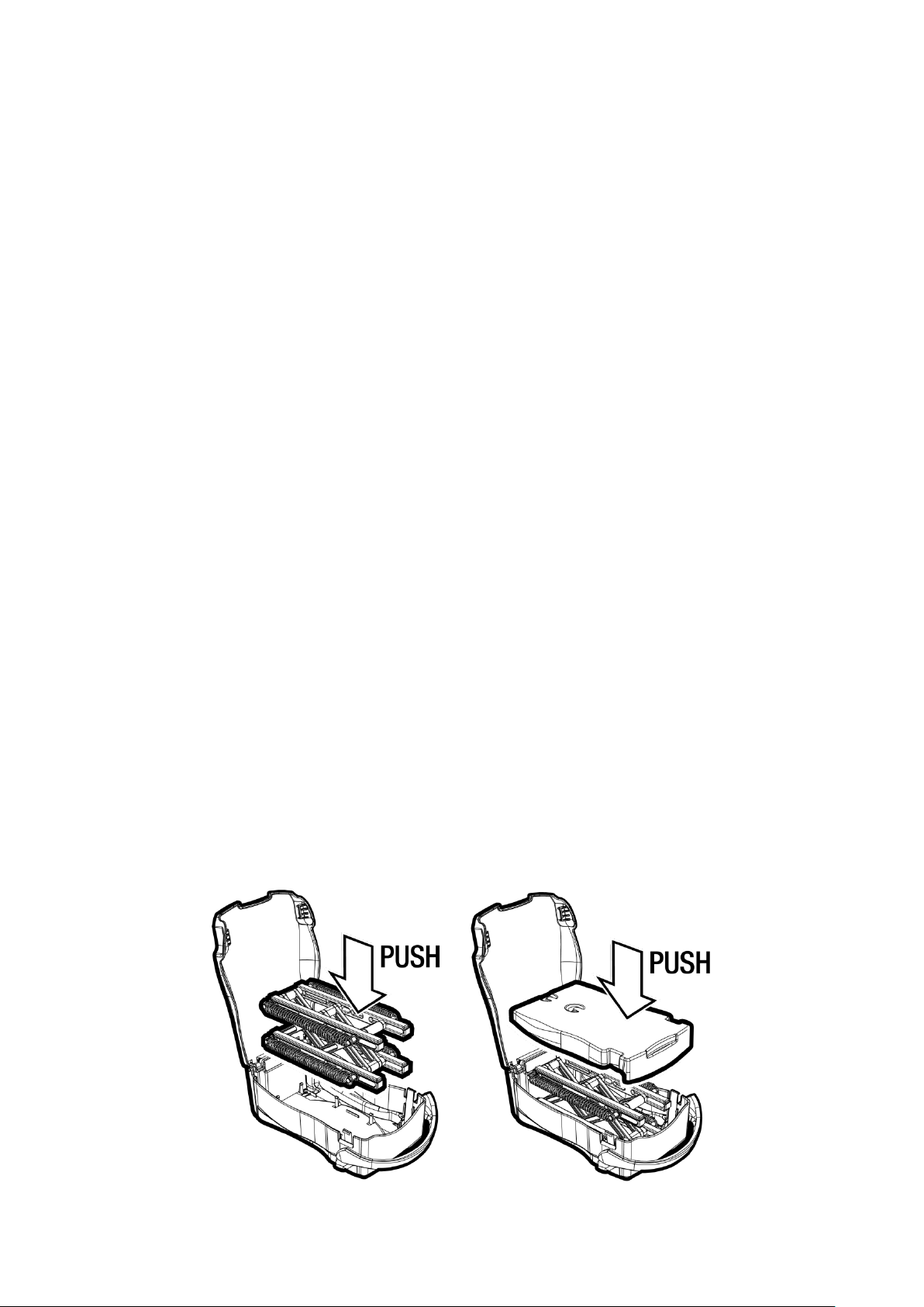
To clean the device, place the Droper Field 1000 on a flat, stable
surface. Open the Droper Field 1000 and pivot the cover
backwards as far as possible. While holding the Droper Field
1000 on the flat surface, firmly grip one of the ends of the plate
and pull it upwards. This will result in the tightening clips
releasing the plate from the mechanism (see diagram).
While holding the Droper Field 1000 on the flat surface, firmly grip
the mechanism and pull it upwards. This will result in the tightening
clips releasing the mechanism from the base of the casing (see
diagram).
Clean the plate, mechanism and casing separately.
Leave to dry.
5.2 Disinfection
After disassembly and cleaning, the different parts removed according to the procedure described
above in point 5.1 Cleaning can be disinfected by soaking, scrubbing or spraying appropriate products.
Solvent-based disinfectants are prohibited.
Particular attention must however be paid during disinfection operations to ensure no damage is
caused to the mechanism's fasteners.
Do not place in a pressure vessel and avoid abrasive scrubbing which may damage the elements.
13 / 16
Do not use cleaning products containing the following ingredients:
AMMONIUM / TRICHLOROETHYLENE
DICHLOROETHYLENE
AMMONIUM CHLORIDE
CHLORINATED or AROMATIC HYDROCARBONS
METHYLENE CHLORIDE
KETONES.
These aggressive agents may damage the plastic parts and cause the device to malfunction.
Please also beware of ALCOHOL-BASED SPRAYS (20% - 40% alcohol content), which may cause the
synthetic materials to tarnish and splinter.
Avoid using iodine solutions capable of irreversibly staining certain clear plastic parts.
The use of disinfectants applied using SPRAYS is ideal for routine disinfection operations and must take
place in compliance with the manufacturer's recommendations and at a distance of 30 cm from the
device, while ensuring that no liquid product is accumulated on the device.
For further information, please contact your company's appropriate department for the provision of
suitable cleaning and disinfection agents.
5.3 Re-installing the components
Once the parts are completely dry, re-insert the two components in the opposite manner to the
disassembly method, presenting each part opposite its tightening clips. The mechanism does not
require a specific forwards/backwards direction of installation. The plate however must be presented
with the fastening hooks facing the rear of the device. Visually check the correct installation of the
different elements.
Ensure that the mechanism is correctly installed facing its clips. Sideways installation could damage
the clips.
14 / 16

6. PERIODIC INSPECTION
The device is designed to operate for 2 years under normal operating conditions, based on a daily
usage rate of 8 infusions per day, i.e. more than 6,000 times. However, the manufacturer advises that
users perform periodic maintenance and inspections to ensure the correct operation of the device,
either by sending it to the manufacturer or distributor, or by using the method described below:
Place a 1000 ml Viaflo infusion bag of NaCl 0.9% marketed by the trademark Baxter in the Droper Field
and introduce the piercing pin of an infusion line without a catheter in the classic OFF position. Drain
the bag and line as described in 2.4 Draining the infusion line and bag. Return the Droper Field 1000
to its horizontal position. Open the infusion line into a recipient placed at the same height as the device
and measure the time required to drain the bag. This time must be between ±320 and ±340 seconds.
7. STORAGE
The device must be stored in a temperature-controlled, dry place.
Recommended relative humidity: 20% to 90%
Recommended storage temperature: - 10°C to + 60°C
8. WARRANTY CONDITIONS
The Droper Field 1000 is guaranteed against any part or manufacture defects for a period of 1 year
from its invoice date. To benefit from the parts and labour warranty from our After-Sales Service or
from an approved service, the following conditions must be complied with:
The device must have been used under the normal operating conditions described
herein.
The device must not have suffered from any deteriorations caused by its storage,
maintenance or incorrect handling.
The device must not have been modified or repaired by persons not authorised by
PROMOVET.
The serial number of the device must not have been modified or erased.
For item returns and repairs, please contact the After-Sales Service.
15 / 16

9. LIFE
v.1 - 09/2013
The Droper Field 1000 was designed to operate for a period of 2 years, calculated based on a daily
usage rate of 8 infusions per day from its commissioning date and for a period of 10 years from its date
of manufacture. The user is responsible for recording the date of first use by any means deemed
appropriate for traceability purposes.
10. USEFUL CONTACTS
Sales Department and After-Sales Services :
Promovet sarl
ZAC de la Route de Beauraing, 1
08600 GIVET (France)
Tel. : + 33 (0)3 24 42 15 71
E-mail : info@promovet.fr
Web sit e : www .dr op er. be
16 / 16
 Loading...