

Page 1
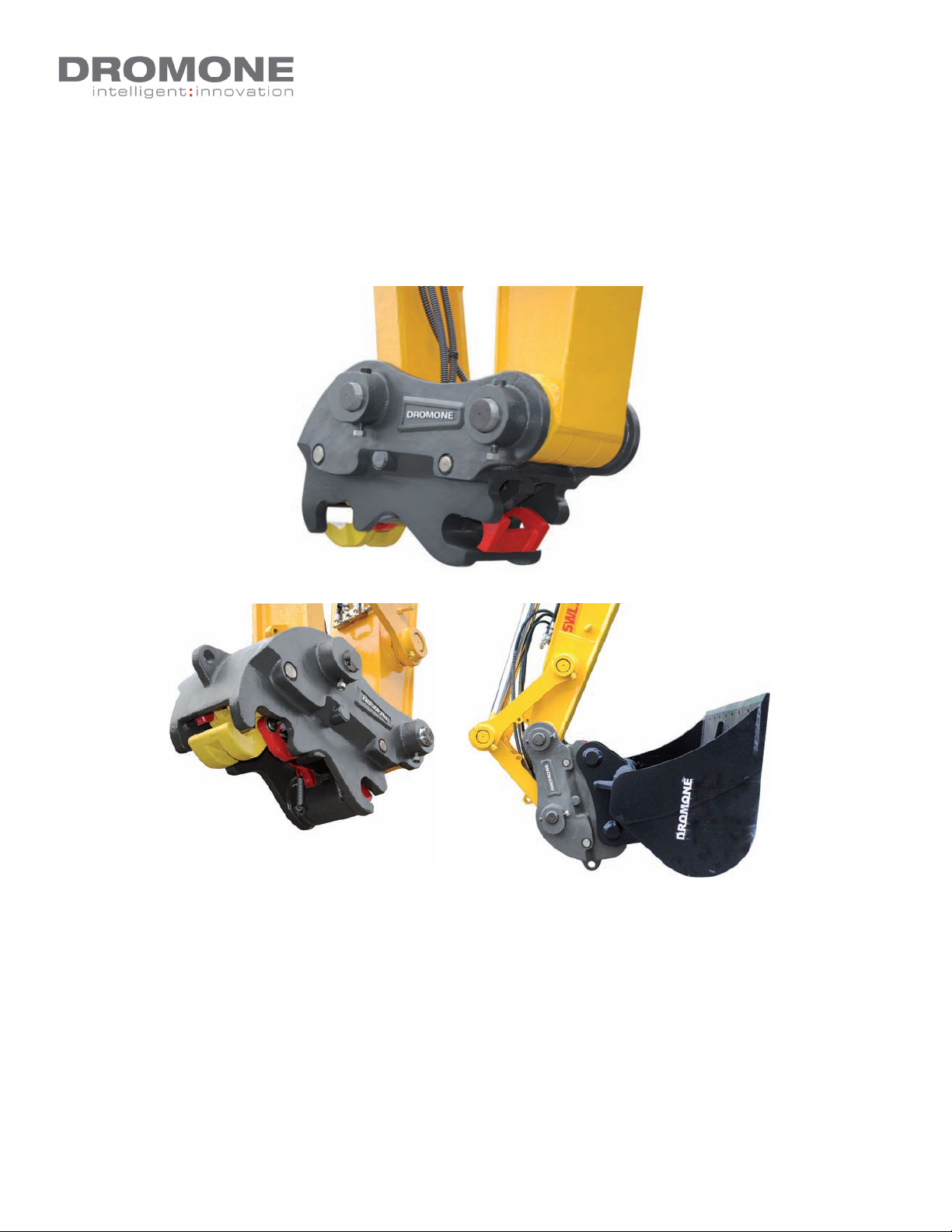
Dromone Multi– Lock Quick Coupler
EXCAVATOR AUTOMATIC QUICK
COUPLER.
OWNER’S MANUAL
IMPORTANT—This manual should be kept in the excavator at all times after the
installation of the Coupler.
Operators should be fully trained with regards to all aspects of this type of coupler.
QMS 22 Dromone Multi– Lock Quick Coupler Author:EOD
REV: D - JAN2012 1 Approved:MS
Page 2

Dromone Multi– Lock Quick Coupler
Index.
Item. Description. Page.
1. Introduction. 3
2. Important Safety Notes. 5
3. Operating Instructions.
A. Bucket / Attachment Pick Up 9
B. Bucket / Attachment Release 12
4. Daily Inspections & Checks 13
5. Spare Part Drawing 14
6. Maintenance Schedule 15
7. Trouble Shooting 17
8. Product Register/ Acceptance 18
9. EC Declaration of Incorporation 19
QMS 22 Dromone Multi– Lock Quick Coupler Author:EOD
REV: D - JAN2012 2 Approved:MS
Page 3

Dromone Multi– Lock Quick Coupler
Introduction.
Thank you for purchasing the Dromone ‘
MULTI-LOCK QUICK Coupler’. This hitch
has been designed and manufactured
with ease of use and operator safety in
mind.
This product has undergone extensive
testing and benchmarking against similar
competitor products and we believe
the Dromone ‘MULTI-LOCK QUICK Coupler’ product is unique, and is the best
available in today’s market place with
safety first.
The ‘MULTI-LOCK QUICK Coupler’ is
characterised in the manner in which
both front and rear pin of the attachment
is are independently hydraulically released by the coupler and both front and
rear pins are independently locked
through the full working cycle.
Dromone Engineering LTD, will
accept no responsibility or liability for equipment installed or op-
erated unless it is full accordance with the information provided in
this manual.
Dromone recommend that genuine Dromone Coupler replacement parts are only
fitted. Please contact Dromone on +353
44 966346 or [email protected] to order
parts, quoting the coupler serial number
This hitch is capable of being fully operated from the comfort and safety of the
machine cab.
This ‘MULTI-LOCK Quick Coupler’s product, when used correctly and with proper
OEM (Original Equipment Manufacturer)
excavator buckets and attachments will
provide a safe and reliable means of
quick attachment and changeover of
various implements, thus allowing the
user to get maximum productivity from
the machine.
To guarantee satisfactory and safe operation of the equipment, we insist that
only experienced and qualified personnel install and operate the product.
Failure to follow the correct procedures
in this manual could result in injury or
death.
QMS 22 Dromone Multi– Lock Quick Coupler Author:EOD
REV: D - JAN2012 3 Approved:MS
Page 4
Dromone Multi– Lock Quick Coupler
This ‘MULTI-LOCK Quick Coupler’
product, when used correctly and with
proper OEM (Original Equipment Manufacturer) excavator buckets and attachments will provide a safe and reliable
means of quick attachment and changeover of various implements, thus allowing the user to get maximum productivity from the machine.
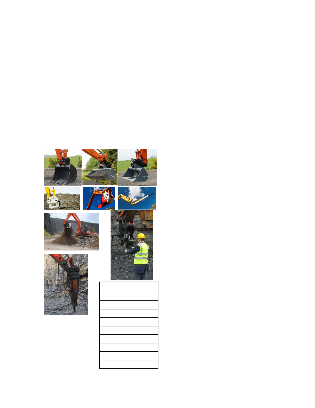
The Coupler can operate with a range of
buckets and a wide range of attachments within the same pin size range,
some of which are illustrated blow in figure 1.
Please note that if the attachment you
wish to use is not on the following list,
please contact Dromone for further information.
Fig 1 . Some of the
attachments suitable
for the ‘MULTI-LOCK
Quick Coupler’
Buckets (all types)
Pallet forks
Ripper
Telescopic jib
Screener
Lifting (using lifting eye)
Rock breaker
Sorting grabs
Compactors
Hydraulic sheers
QMS 22 Dromone Multi– Lock Quick Coupler Author:EOD
REV: D - JAN2012 4 Approved:MS
Page 5

Dromone Multi– Lock Quick Coupler
Important Safety Notes
Please Read Carefully.
1. As a new owner / operator of a Dromone ‘MULTI-LOCK Quick Coupler’ it is
very important that you take time to acquaint yourself with the main features of
the hitch and the requirements for its
safe operation and maintenance.
Therefore, we recommend that you
study the contents of this booklet very
carefully and be fully familiar with its
contents before commencing work.
Always treat couplers with the respect
they deserve.
2. Great care must be taken when working on or with the ‘MULTI-LOCK Quick
Coupler’. Never attempt to work on, or
carry out maintenance to this product
without first ensuring that it has been
made safe, and that the machine to
which it is attached is switched off.
3. In the case of a hydraulically operated
hitch. Even with the machine switched
off the hydraulic circuits may remain
pressurised so care must be taken when
connecting / disconnecting hydraulic
hoses.
4. While the ‘MULTI-LOCK Quick Coupler’ is designed and proven to work with
most available buckets and other attachments. Dromone do not approve the use
of mechanical pulverises, mechanical
shears, mechanical stump grinders and
such tools with this coupler. Limited use
of breakers with the coupler is permitted.
Warranty will be void if such attachments
are used with this coupler.
5. Regardless of the bucket or attachment being used with the ‘MULTI-LOCK
Quick Coupler’ they must be used in
strict accordance with their individual
manufacturers guide lines and instructions.
6. In order to ensure that you get the
most from your ‘MULTI-LOCK Quick Coupler’ product we have set out in this
booklet some recommended service and
maintenance checks. These should be
carried out on a regular basis and any
damaged parts should be replaced immediately.
7. Never attempt to modify either the
Dromone Multi Lock Quick Coupler or the
machinery onto which it is intended to be
attached without first receiving approval
from Dromone Engineering personnel.
Unauthorised modification of the Quick
Coupler or the host machine can seriously impair the performance of the
equipment and could cause serious injury
to personnel.
8. It is the responsibility of all persons
involved in the installation, maintenance
and operation of the Dromone Quick
Coupler to ensure their own personal
safety by wearing suitable protective
clothing, safety footwear, Hi-visibility
vests and ear & eye protection where appropriate.
9. If you should have any difficulty with
your Dromone Multi Lock Quick Coupler
which is not addressed in this manual,
then you should contact Dromone Engineering Ltd. Immediately at the numbers
provided on the back of this manual.
10. Although every effort has been made
to optimise the strength and durability of
the Dromone Multi Lock Quick Coupler, it
should be noted that the typical environ-
QMS 22 Dromone Multi– Lock Quick Coupler Author:EOD
REV: D - JAN2012 5 Approved:MS
Page 6

Dromone Multi– Lock Quick Coupler
ment in which the coupler is likely to be
working can be extremely harsh and detrimental to all types of machinery. For this
reason, Dromone Engineering highly
recommends that; as well as the regular
maintenance checks, certain components
be replaced as a matter of course after
reaching a pre-specified no. of working
hours.
Intermittent problems can be symptoms
of imminent failure and if these are experienced with key control components
such as the control box or solenoid valve,
these components should be replaced immediately.
Details of specific components and their
expected normal working life can be
found in the Maintenance section of this
manual. Please take the time to become
acquainted with these components and to
monitor their working age.
Only genuine Dromone parts must
be used to service this Quick Coupler.
Dromone Engineering Ltd. reserves
the right to waive liability if non
genuine parts are fitted to this Coupler.
11. It is important to note that if you or
your representative is responsible for the
initial installation of the Dromone Quick
coupler, especially in regard to the hydraulic / electrical system; you must take
the full responsibility to make sure the
installation is carried out in strict accordance with Dromone Engineering’s instructions. Any failure to do so may allow
the unsafe operation of the coupler and
result in serious injury or death, with the
installer being found to be liable.
12. Other than the structural integrity of
the Dromone Multi Lock Quick Coupler,
the most important component(s) in this
coupler are the two hydraulic cylinders
and the front and rear pin locking mechanisms.
It is imperative that to ensure the continued safe and effective use of this coupler,
a daily check be carried out to monitor
wear, blockages and other damage that
can possibly occur to the detriment of the
system’s safe operation.
While every effort has been made by Dromone Engineering Ltd. To provide a safe,
durable and effective product to work in a
typically harsh environment, it must be
stressed that it is the responsibility of the
owner / user to keep the system serviced
and in good working order. The machine
operator and / or owner could be held to
be negligent if they either fail to keep the
system in good order.
13. It is essential to ensure continued
safe operation of the Dromone Multi Lock
Quick Coupler, that along with regular
maintenance checks and services carried
out on the coupler; close attention be
paid to the presence and condition
(legibility) of all the decals in the machine’s cab.
If one or more of these decals become
damaged or lost, it is essential that they
be replaced immediately. Dromone Engineering has supplied an extra set of decals with this manual for this eventuality.
If you have not received these decals you
should contact your dealer immediately. If
you have further need for decals, you can
contact Dromone directly at the address /
Tel no. printed in this manual.
PLEASE MAKE SURE THAT THE INCAB OPERATION INSTRUCTION DECALS ARE MOUNTED IN THE MACHINE CAB IN AN EASILY VISIBLE
QMS 22 Dromone Multi– Lock Quick Coupler Author:EOD
REV: D - JAN2012 6 Approved:MS
Page 7
Dromone Multi– Lock Quick Coupler
LOCATION CONVENIENT TO THE
OPERATOR & THAT THIS MANUAL
IS AVAILBLE IN THE MACHINE CAB.
14. Lifting eye can only be used with the
machine if there is a hose burst check
valve on the boom. It is the responsibility
of the fitter to disable the lifting eye, if
the safety check valves are not incorporated
If the coupler is fitted with a lift eye,
please inspect daily before use for wear,
cracks and fatigue. If damaged do not
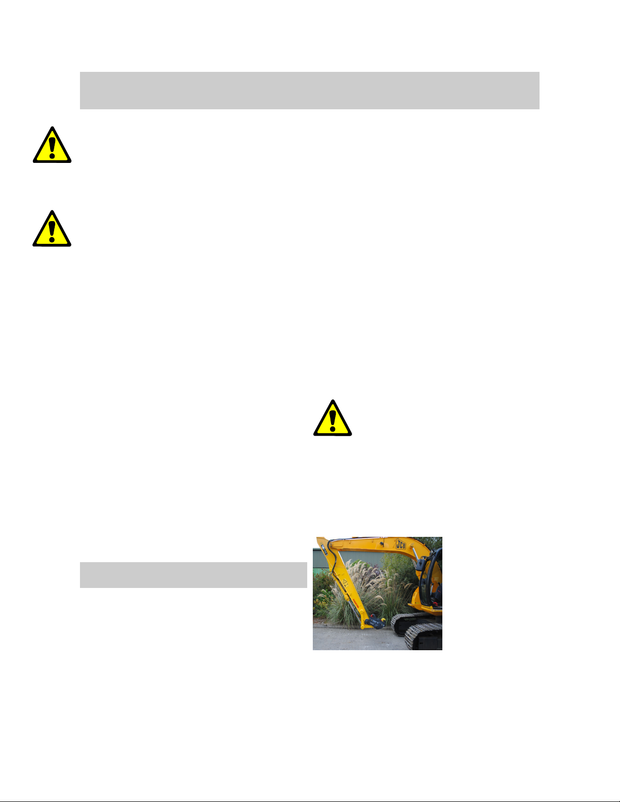
use.
Always use approved lifting shackle and
chains in conjunction with the lift eye.
Check the SWL (Safe Working Load) that
is stamped on the coupler and ensure
the lifting equipment is compatible.
Always check the excavator manual for
the machine SWL as this determines the
lifting capacity of the machine. This SWL
should never be exceeded under any
circumstance.
Always remove the attachment on the
coupler prior to using the lift eye.
No other part of the coupler may be used
for lifting other than the lift eye.
The lift eye on the coupler has been
tested and stamped by Dromone, this
test is valid for 12 months from first date
of purchase, there after it is the responsibility of the machine owner to insure the
lift eye remains compliant to each countries national standard.
15. The quick hitch should only be fitted
to the machine referred to on the Serial
number plate or the declaration of incor-
poration. Should the model on the badge
be different on the badge, permission
should be sought from Dromone engineering before commencing fit-up.
16. Sequence of Operation of the
Dromone ‘Multi Lock’ Automatic Coupler:
Opening:
•
Rear Lock Hydraulically Opens
•
Latching Hook Retract Hydraulically.
•
Front Locking Mechanism Mechanically Opens.
17. The operating instructions contained
in this manual are a guideline for use with
the Dromone Control Box. Please contact
you plant department or training department if another system has been implemented at installation. A copy of this may
be found in the appendix at the end of the
manual. Please contact your plant or
training department for a copy of this in-
18. The working range of the machine
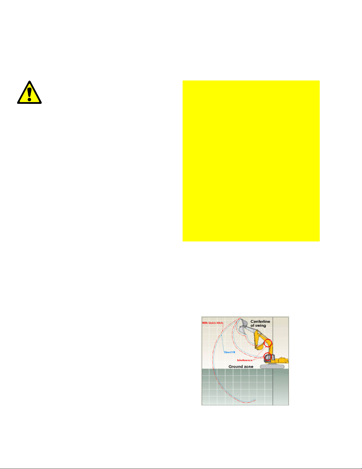
can change with the incorporation of a
quick hitch. This includes the following:
•
The bucket is more liable to interfere with the dipper arm and possibly the cab in which can lead to injury or death (
Figure 2
).
Fig 2. Possible interference
QMS 22 Dromone Multi– Lock Quick Coupler Author:EOD
REV: D - JAN2012 7 Approved:MS
Page 8

Dromone Multi– Lock Quick Coupler
•
Break out force is reduced at the
tip of the bucket due to the longer
distance from the pivoting area.
•
As can be seeing from
figure 2
above this is ideally the danger
zone and it follows a 360 degree
axis to the machine from the centreline of swing. As well as this, the
working radius of the machine increases due to the extra distance
between the bucket and the dipper
arm.
•
Maximum operating capacity is limited with the use of quick coupler.
Refer to excavator owners manual
for further information on max operating loads.
20. Please note that under no circumstance, does Dromone engineering authorize the transport of people with a
quick hitch, even if the quick hitch is designed to do so.
QMS 22 Dromone Multi– Lock Quick Coupler Author:EOD
REV: D - JAN2012 8 Approved:MS
Page 9
Dromone Multi– Lock Quick Coupler
Operating Instructions
The operating instructions contained in
this manual are a guideline for use with
the Dromone Control Box. Please contact you plant department or training
department if another system has been
implemented at installation. A copy of
this may be found in the appendix at the
end of the manual. Please contact your
plant or training department for a copy
of this instruction.
To guarantee satisfactory and safe operation of the equipment, it is strongly
recommended that the ‘MULTI-LOCK
Quick Hitch’ be installed and fitted by
trained personnel only.
Installation of the ‘MULTI-LOCK Quick
Hitch’ must be in accordance with the
instructions provided in this manual, any
deviation from the instructions given
here needs to be authorised by Dromone Engineering personnel.
Any difficulty with interpretation of the
installation instructions in this manual
should be resolved between the fitter
and Dromone Engineering, before proceeding any further - IF IN DOUBT
ASK.
secured properly in place.
B. Ensure that the ‘MULTI-LOCK
Quick Coupler’ has been left safe
after previous use / operation.
C. Ensure that the area within the
maximum machine swing radius
is clear of all personnel and
obstacles.
D. If the In-Cab control system is not
supplied by Dromone, this may
affect the performance and safety
of the coupler. Always check the
sequence and function matches
the sequence outlined in this
manual.
Procedure:
1. From the operators seat in the
machine cab the ‘MULTI-LOCK
Quick Hitch’ must be fully
crowned inwards to the transport
position in order to disengage the
automatic latching system. Fully
extend the bucket cylinder and
hold over relief.
Bucket/Attachment Pickup
Before attaching to a bucket or any
other attachment it is important to
check for the following. Familiarise
yourself with the coupler and machine
controls prior to use with attachments.
A. The attachment is fitted with the
Fig 2. Excavator in transport
position
correct pins at the correct centre
distances and that they are
QMS 22 Dromone Multi– Lock Quick Coupler Author:EOD
REV: D - JAN2012 9 Approved:MS
Page 10
Dromone Multi– Lock Quick Coupler
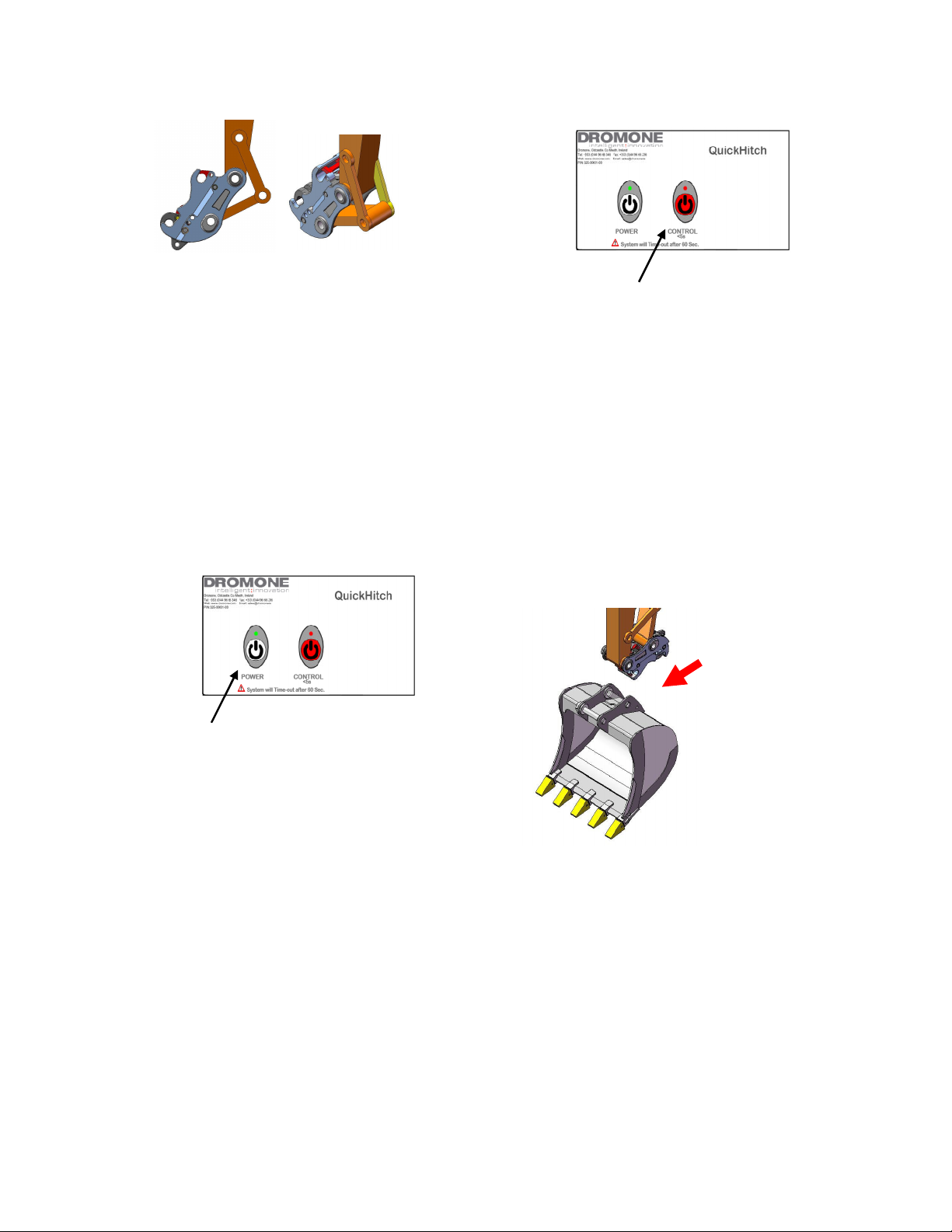
Fig 4. Hitch in transport position
2. Press the ’POWER’ button on the incab control panel to the, The visual Led
will pulsate GREEN and activate an audible buzzer (continuous tone) in the machine cab (
Figure 5
).
NOTE: If no further action is taken
within 5 seconds the unit will
automatically ‘LOCK OUT’, the
indicators will go out and the green
LED light will return to a constant
green light.
Fig 6. Press ’CONTROL’ Button
NOTE: After ’CONTROL’ button is
pressed, the system will activate a
warning signal at 55 seconds, and
after 60 seconds the hitch will reset
to a closed position.
4. Manoeuvre the ‘MULTI-LOCK Quick
Coupler’ to line it up with the bucket or
implement to be picked up (
Figure 7
)
Fig 5. Switching control box on
3. Activation of cylinders:
Press the ’CONTROL’ button within 5 seconds from switch on. The status indicator
light will illuminate to a flashing red signal and the buzzer will also change from
a continuous tone to a pulsating tone.
This indicates that a positive supply is
being sent to the solenoid valve, which in
turn operates the both lock cylinder.
Fig 7. Manoeuvring
into bucket
5. Lower the
‘MULTI-LOCK Quick Coupler downwards
and slide forward to engage the front
jaw of the ‘MULTI-LOCK Quick Hitch’
over the nearest bucket pin. Rotate the
‘MULTI-LOCK Quick Hitch’ clockwise to
line up the second bucket pin (furthest
from mach.)
QMS 22 Dromone Multi– Lock Quick Coupler Author:EOD
REV: D - JAN2012 10 Approved:MS
Page 11
Dromone Multi– Lock Quick Coupler
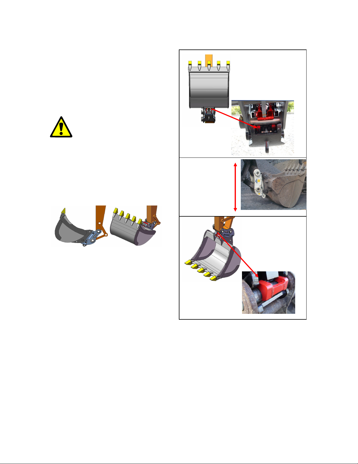
6. When both attachment pins are seated
in the ‘MULTI-LOCK Quick Coupler’ jaws,
rotate the attachment fully inwards using
the excavator bucket cylinder (
Figure 7)
.
This manoeuvre will ensure that the attachment is fully seated in the ‘MULTILOCK Quick Hitch’ jaws.
7. Press ‘POWER’ button the indicator
light will go out and audible buzzer will
stop sounding in excavator cab. The
main cylinder will extend and lock the
latching hooks over the attachment pin.
1. Visually confirm rear latch
2. Complete
bump test to
ensure that rear
lock is properly
secure
Fig 9. Curling fully inwards and apply overpressure for 3-5 seconds
8. As a final check that this procedure
has been carried out correctly, the following checks should be verified in the
following order.
1. Visually confirm rear latch is engaged
2. Complete bump test to ensure
that rear lock is properly secure
3. Visually confirm the front lock is
engaged
3. Visually confirm the
front lock is engaged
Fig 10. Final checks
With the confirmation of these checks
the coupler is now ready for use. (
10)
QMS 22 Dromone Multi– Lock Quick Coupler Author:EOD
REV: D - JAN2012 11 Approved:MS
Figure
Page 12
Dromone Multi– Lock Quick Coupler
Bucket/Attachment Release
Before attempting the release of a
bucket or any other attachment it is important to check for the following.
A. Ensure that the area within the
maximum machine swing radius
is clear of all personnel and
obstacles.
B. Put attachment on level ground
to ensure that it does not roll
over.
Procedure:
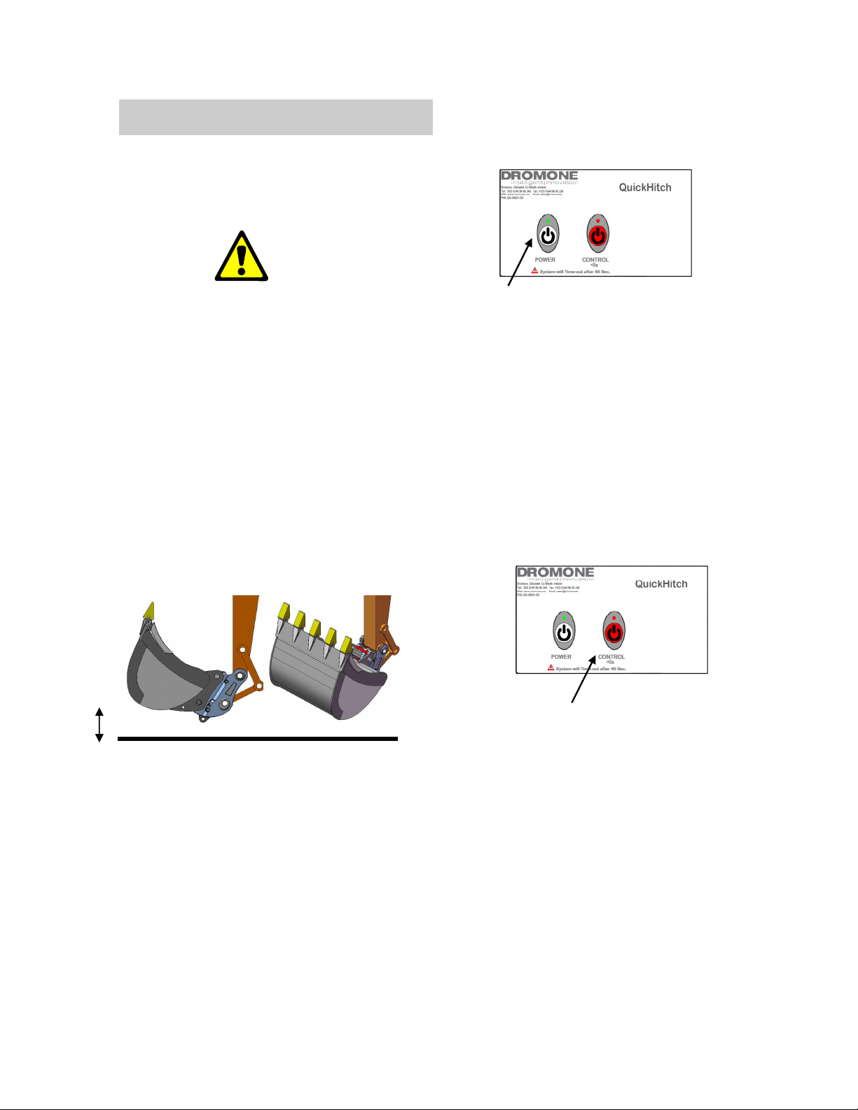
1.Lower the ‘Quick Coupler and attachment to the ground with the ‘Quick Coupler’ rotated fully inwards towards the
machine in order to disengage the automatic latching system.
LED light will return to a constant
green light.
Fig 12. Switching control box on
3. Activation of cylinders:
Press the ’CONTROL’ button within 5 seconds from switch on. The status indicator
light will illuminate to a flashing red signal and the buzzer will also change from
a continuous tone to a pulsating tone.
This indicates that a positive supply is
being sent to the solenoid valve, which in
turn operates the both lock cylinder.
200mm
Fig 11. Lowering the bucket
Ground
Fig 13. Press ’CONTROL’ Button
NOTE: After ’CONTROL’ button is
pressed, the system will activate a
2. Press the ’POWER’ button on the incab control panel to the, The visual Led
will pulsate GREEN and activate an audi-
warning signal at 55 seconds, and
after 60 seconds the hitch will reset
to a closed position.
ble buzzer (continuous tone) in the machine cab (
Figure 12
).
NOTE: If no further action is taken
within 5 seconds the unit will
automatically ‘LOCK OUT’, the
indicators will go out and the green
QMS 22 Dromone Multi– Lock Quick Coupler Author:EOD
REV: D - JAN2012 12 Approved:MS
Page 13
Dromone Multi– Lock Quick Coupler
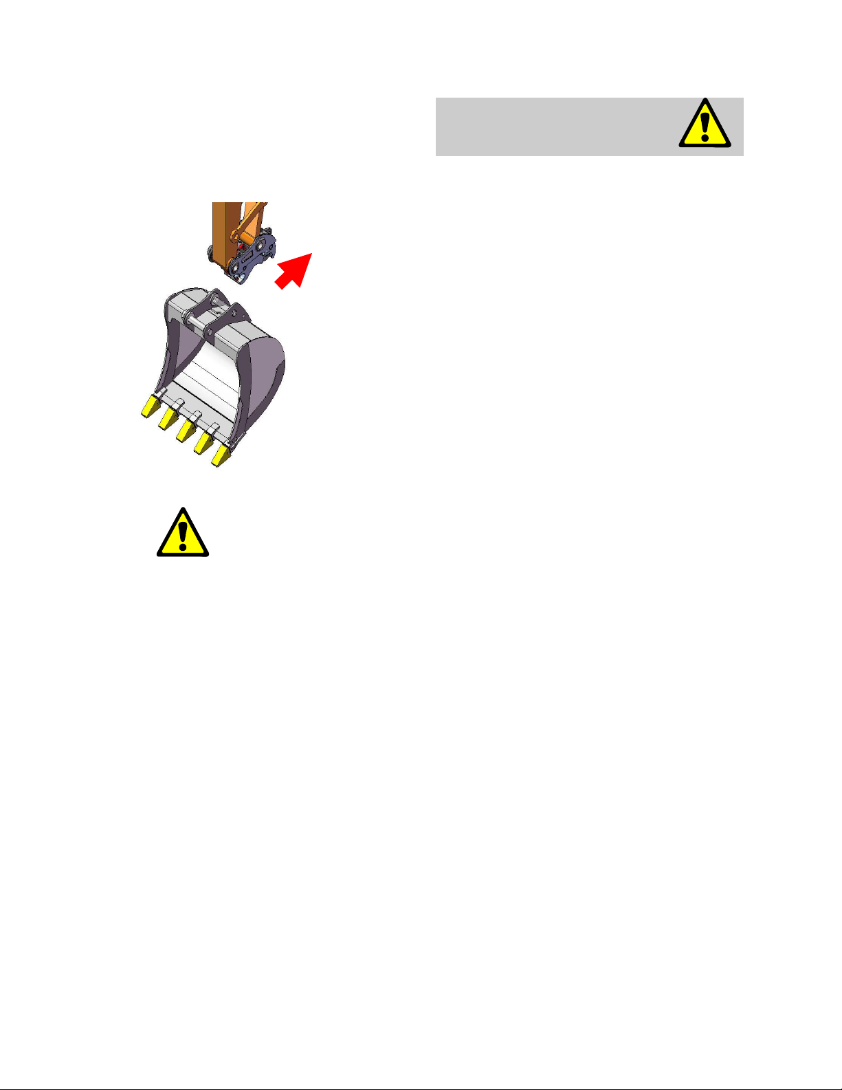
4. Manoeuvre the ‘Quick Hitch’ rearwards, away from the machine and this
will disengage the ‘Quick Hitch’ from the
bucket or other attachment (figure 14).
Fig 14. Moving
the ‘Quick hitch'
away from the
bucket
DAILY INSPECTION &
CHECKS.
The following checks should be carried
out on a daily basis.
1. Check the main frame for cracks or
weld failure.
2. Check that the Quick Coupler components are not damaged or showing signs of wear.
3. Check the attachment pins for
damage or undue wear.
4. Check for any sign of damage or
clogging of both automatic locking
mechanisms.
5. Check for oil leaks from the
hydraulic cylinders and hose
connections.
6. Check that all nuts & bolts used to
secure pins are locked tight.
5. The next stage is to set the switch to
the ‘OFF’ position, the indicator light will
go out and the audible buzzer will stop
sounding in the machine cab. The ‘Quick
Coupler’ cylinder will extend and lock the
hitch latching hooks. This manoeuvre will
also activate the automatic locking system.
7. Grease hitch daily, all pins and
bushings should be greased. Grease
nipples are provided at cylinder
bushings and at the latching hooks
to facilitate access for this purpose.
8. Clean coupler of all dirt and debris,
ensure all labels are clean and
legible at the end of each shift.
9. Inspect lift eye for wear, damage or
cracks.
QMS 22 Dromone Multi– Lock Quick Coupler Author:EOD
REV: D - JAN2012 13 Approved:MS
Page 14
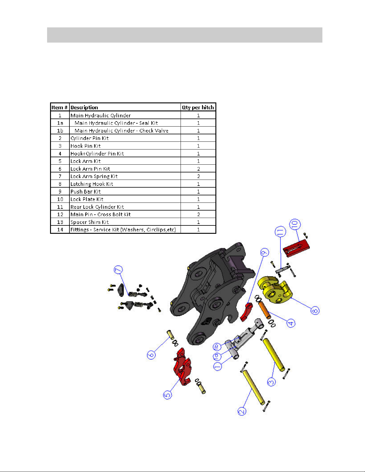
PARTS LIST—ORDERING SPARE PARTS
Dromone Multi– Lock Quick Coupler
All Dromone MULTI-LOCK Quick Couplers are labelled with a unique serial number.
The serial number is located on the mai body of the frame.
At the time of ordering spare or replacement parts, you will be required to provide
the serial number and a description of the part(s) you require. Please see below
reference illustration drawing of spare parts for the coupler.
QMS 22 Dromone Multi– Lock Quick Coupler Author:EOD
REV: D - JAN2012 14 Approved:MS
Page 15
Dromone Multi– Lock Quick Coupler
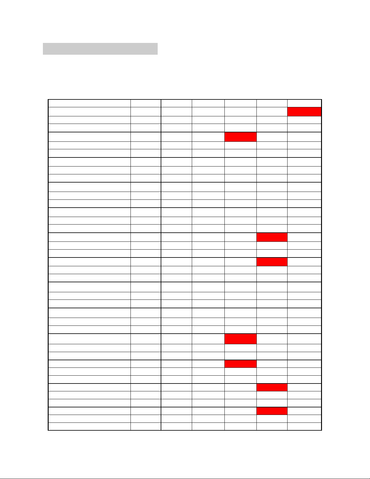
Maintenance Schedule
The table below is to be used as a guideline in the maintenance program of the
coupler. The maintenance log should be update and signed off at the recommended
hourly interval. If parts are damaged or worn outside of the schedule below these
Description Hourly Interval
1000 2000 3000 4000 5000 6000
Latching Hook Assy (Ref 1)
Signed
Date
Bucket Pins (Ref 4 and 5)
Signed
Date
Hydraulic Cylinder ~Lg (Ref 12)
Signed
Date
Hydraulic Cylinder ~S (Ref 11)
Signed
Date
Front lock (Ref 7)
Signed
Date
Cylinder Pin (Ref 6)
Signed
Date
Hook Assy Pin (Ref 3)
Signed
Date
Cylinder & Hook Pin (Ref 2)
Signed
Date
Rear lock (Ref 10)
Signed
Date
Check Valves (Ref 16)
Signed
Date
Seal Kits (Ref 15)
Signed
Date
Push Bar (Ref 8)
Signed
Date
Front lock pin kit (Ref 9)
Signed
Date
INSPECT INSPECT INSPECT INSPECT INSPECT REPLACE
INSPECT INSPECT INSPECT REPLACE INSPECT INSPECT
INSPECT INSPECT INSPECT INSPECT INSPECT INSPECT
INSPECT INSPECT INSPECT INSPECT INSPECT INSPECT
INSPECT INSPECT INSPECT INSPECT INSPECT INSPECT
INSPECT INSPECT INSPECT INSPECT REPLACE INSPECT
INSPECT INSPECT INSPECT INSPECT REPLACE INSPECT
INSPECT INSPECT INSPECT INSPECT INSPECT INSPECT
INSPECT INSPECT INSPECT INSPECT INSPECT INSPECT
INSPECT INSPECT INSPECT REPLACE INSPECT INSPECT
INSPECT INSPECT INSPECT REPLACE INSPECT INSPECT
INSPECT INSPECT INSPECT INSPECT REPLACE INSPECT
INSPECT INSPECT INSPECT INSPECT REPLACE INSPECT
QMS 22 Dromone Multi– Lock Quick Coupler Author:EOD
REV: D - JAN2012 15 Approved:MS
Page 16

Dromone Multi– Lock Quick Coupler
Maintenance log
Description Hourly Interval
Signed
Date
Signed
Date
Signed
Date
Signed
Date
Signed
Date
Signed
Date
Signed
Date
Signed
Date
Signed
Date
Signed
Date
Signed
Date
QMS 22 Dromone Multi– Lock Quick Coupler Author:EOD
REV: D - JAN2012 16 Approved:MS
Page 17
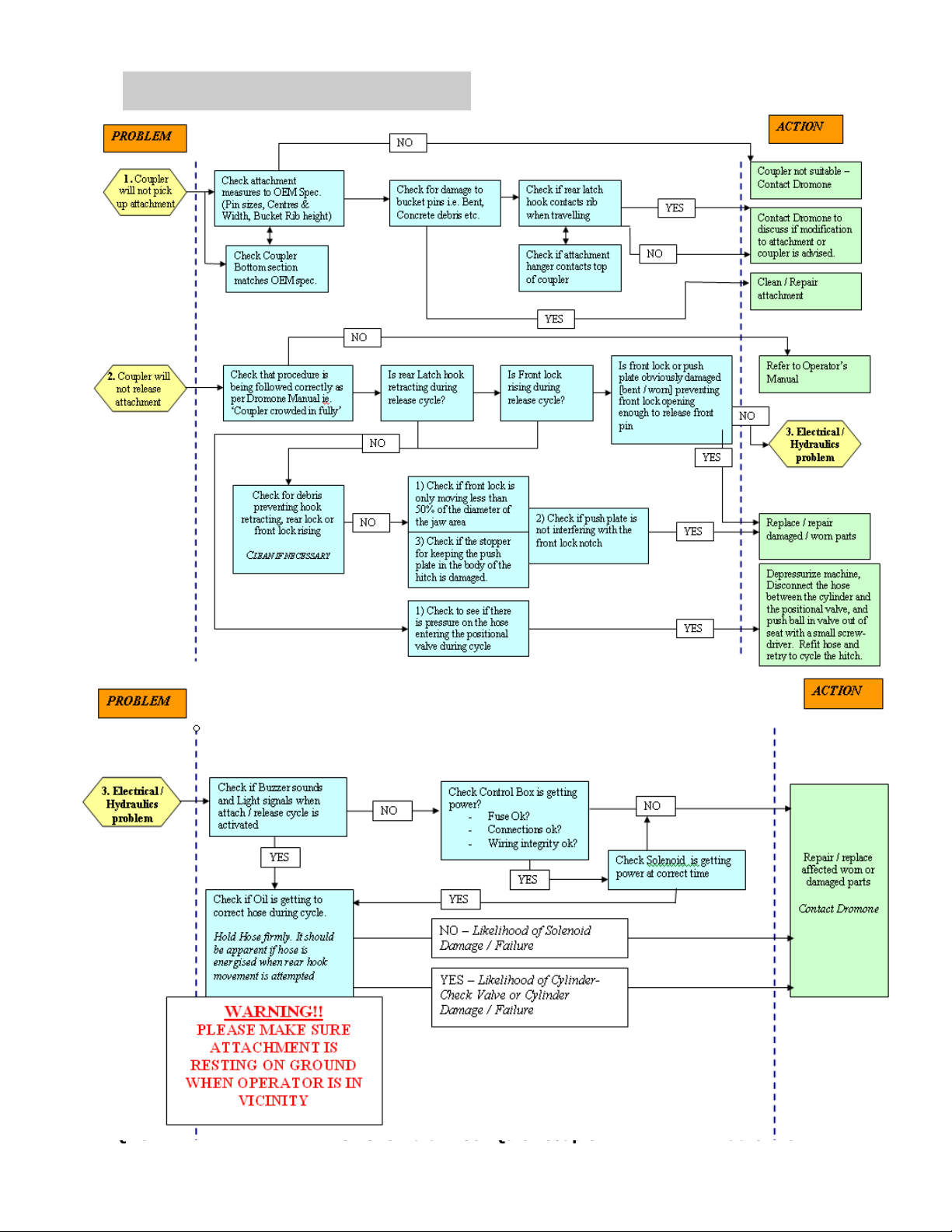
Trouble Shooting
Dromone Multi– Lock Quick Coupler
QMS 22 Dromone Multi– Lock Quick Coupler Author:EOD
REV: D - JAN2012 17 Approved:MS
Page 18

Dromone Multi– Lock Quick Coupler
Form No. B185 Rev A
EC DECLARATION OF INCORPORATION
We, Dromone Engineering Limited,
Dromone,
Oldcastle,
Co. Meath,
Ireland.
Declare that the following product:
Dromone __________________________(Product Name) Serial Number:_________________
_____________________(Type Model)
Is destined to be combined with other machines, and is in conformity with the provisions of the following
European Directives:
Council directive 2006/42/EC
And the following standards:
ISO 14121-1:2007 (replaces EN 1050)
EN ISO 12100-1:2003 +A1:2009 (replaces EN 292)
AS 4772-2008
EN474-1: 2006
Completed at Dromone Engineering Limited, Dromone, Oldcastle, Co. Meath, Ireland.
Signed: Martin Segarty………………………………………………..
Position: Product Manager………………………………….
Date: __ __ / __ __ / 20__ __
ATTENTION!
The attention of the specifier, purchaser, installer, or user is drawn to special measures and limitations to use which
must be observed when the product is taken into service to maintain compliance with the above directives. Details of
these special measures and limitations to use are available on request, and are also contained in the product manuals
QMS 22 Dromone Multi– Lock Quick Coupler Author:EOD
REV: D - JAN2012 18 Approved:MS
 Loading...