

Page 1

DroMightTM Rudder Lock Installation Instructions
For your Vans Aircraft RV-14
For a color version of the instructions below, please visit www.terrestrialimaging.com/controllocks/rv14
Please read all directions prior to installation and first use.
Thank you for purchasing the DroMightTM Rudder Lock. You are now the proud owner of the best,
safest, and easiest to use rudder locking systems for the Vans RV14 Aircraft. This revolutionary product
prevents wind from causing unexpected movements of the rudder control surface and can be secured
from within your aircraft while parked on the ground. The DroMightTM Rudder Lock is significantly safer
than rudder locks that are installed on the exterior of the aircraft. The likelihood of forgetting to remove
the DroMightTM Rudder Lock from the interior of your aircraft prior to your next flight is significantly
reduced.
As an owner of the Vans RV14, you know that the large rudder can easily be damaged by a gust of wind
when parked on the ground. In fact, many rudders have been damaged immediately after pulling the
aircraft out of the hangar, or while parked on the ramp during a fuel stop. It only takes a second or two
for a gust of wind to force the rudder against its stops resulting in a damaged rudder. The DroMightTM
Rudder Lock solves this problem and is the best insurance money can buy against rudder damage from
wind gusts while parked on the ground.
There is only one thing more important than the protection of your rudder and that is the protection
and safety of the pilot and passengers. A Rudder Lock can pose a serious safety hazard if it is not
removed before an aircraft’s movement. A locked rudder can result in an inoperative control service
and lead to a crash and loss of life. External rudder locks can easily be forgotten and have led to many
accidents over the years. Internal rudder locks are much safer as they typically make it difficult or
impossible to move the aircraft without removing the rudder lock. The DroMightTM Rudder Lock is
installed inside the aircraft, and makes it nearly impossible for the pilot to place their feet on the
rudders without first removing the rudder lock.
Regardless of how safe a rudder lock might be, or how it is installed, mistakes happen and it is still
possible to forget to remove it. We caution all pilots and users of the DroMightTM Rudder Lock to modify
their pre-flight check list to include “Remove and Stow DroMightTM Rudder Locks”. Never skip this item
or any other items on your checklist as your life might depend on it.
Page 1
Page 2
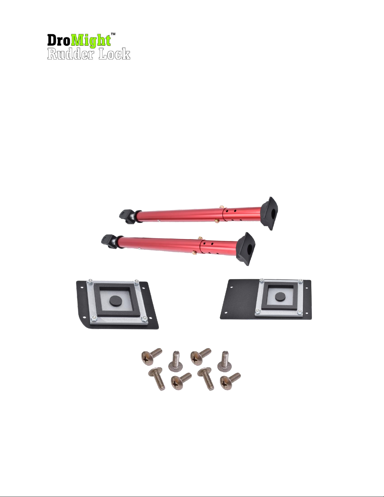
Kit Contents
Your DroMightTM Rudder Lock kit includes the following items:
2 x Adjustable Red Anodized Aluminum Rudder Locking Tubes
1 x Black Anodized Rudder Locking Base Plate (small)
1 x Black Anodized Rudder Locking Base Plate (big)
8 x AN526C832R7 screws
If any of these items are missing from your kit, please notify us immediately.
Page 2
Page 3
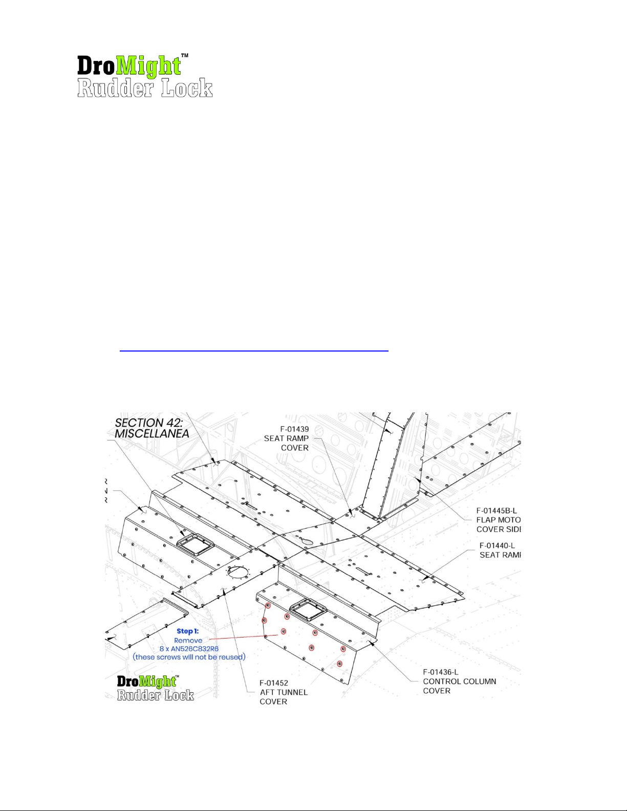
Installation
Installation of the DroMightTM Rudder Lock is very simple and can be accomplished in only a few
minutes. The only tool required is a medium sized Phillips screwdriver. You will be removing eight
AN526C832R6 screws, installing two base plates on the left side control column cover (Vans Aircraft part
number F-01436-L), and installing eight new AN526C832R7 screws. If you have carpeting or fabric that
covers F-01436-L control column cover, you will have to remove enough material to allow room for the
two base plates to be installed flush against the control column cover. Follow the instructions below to
permanently install the DroMightTM Rudder Lock base plates to the control column cover on the left side
of the aircraft.
If you are interested in watching our installation video, please enter the link below into your web
browser:
https://youtu.be/YzPrJpWGAIQ?si=YQI6gy70nkI_Scpn
Step 1: Remove existing screws.
Page 3
Page 4
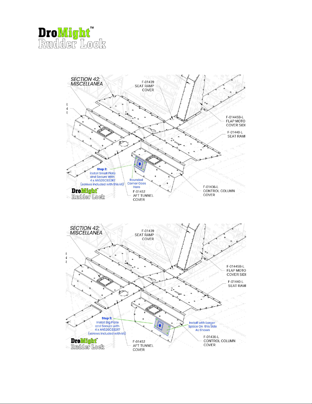
Step 2: Install small base plate.
Step 3: Install big base plate.
Page 4
Page 5
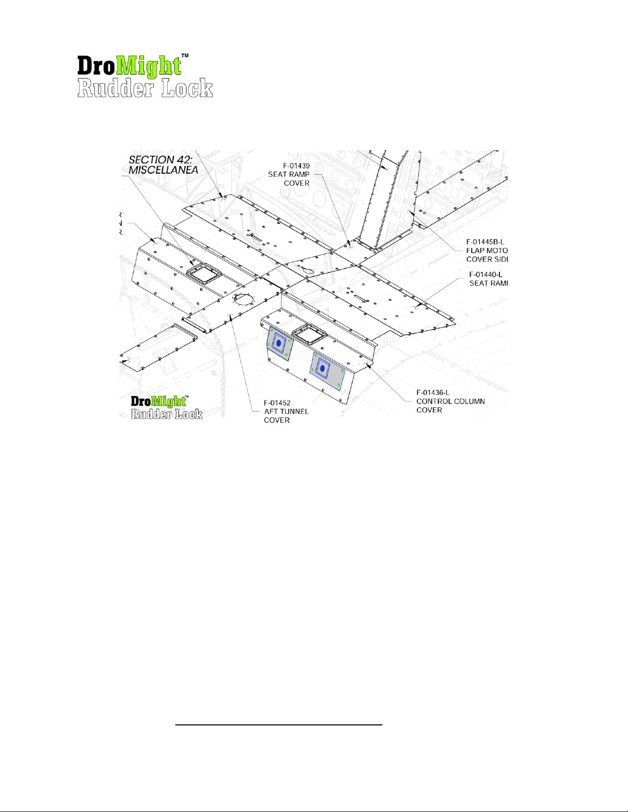
Step 4: Inspect your work. Base plate installation complete.
With the two base plates installed, secure the rudder pedals on the left side of the aircraft as follows:
1. Select one red tube and place the black tip of the tube over the left rudder’s lower steel tubing
so that the rudder is fully captured in the tip of the red tube as shown in figure 1.
2. Rotate the tube so that the yellow “Remove Before Flight” sticker is facing up and then take the
rear side of the red tube (black plastic rocker) and place it in the center of the base plate making
sure it is fully seated in the base plate. Put slight pressure on the right rudder pedal to put
pressure on the red tube to secure in place as shown in figure 2.
3. Select the second red tube and place the black tip of the tube over the right rudder’s lower steel
tubing so that the rudder is fully captured in the tip of the red tube as shown in figure 1.
4. Rotate the tube so that the yellow “Remove Before Flight” sticker is facing up and then take the
rear side of the red tube (black plastic rocker) and place it in the center of the base plate making
sure it is fully seated in the base plate. You will need to compress the red tube by pushing
forward in order for the tube to snap into the base plate as shown in figure 2.
5. Pull up and down on both red tubes and inspect them carefully to make sure they are securely
locked into both the base plate and on the bottom of the rudder pedals. See figure 3.
CAUTION: Always remove both red rudder locking pedals before flight. Modify your pre-flight check list
to include the words “Remove and Stow DroMightTM Rudder Locks”.
Page 5
Page 6
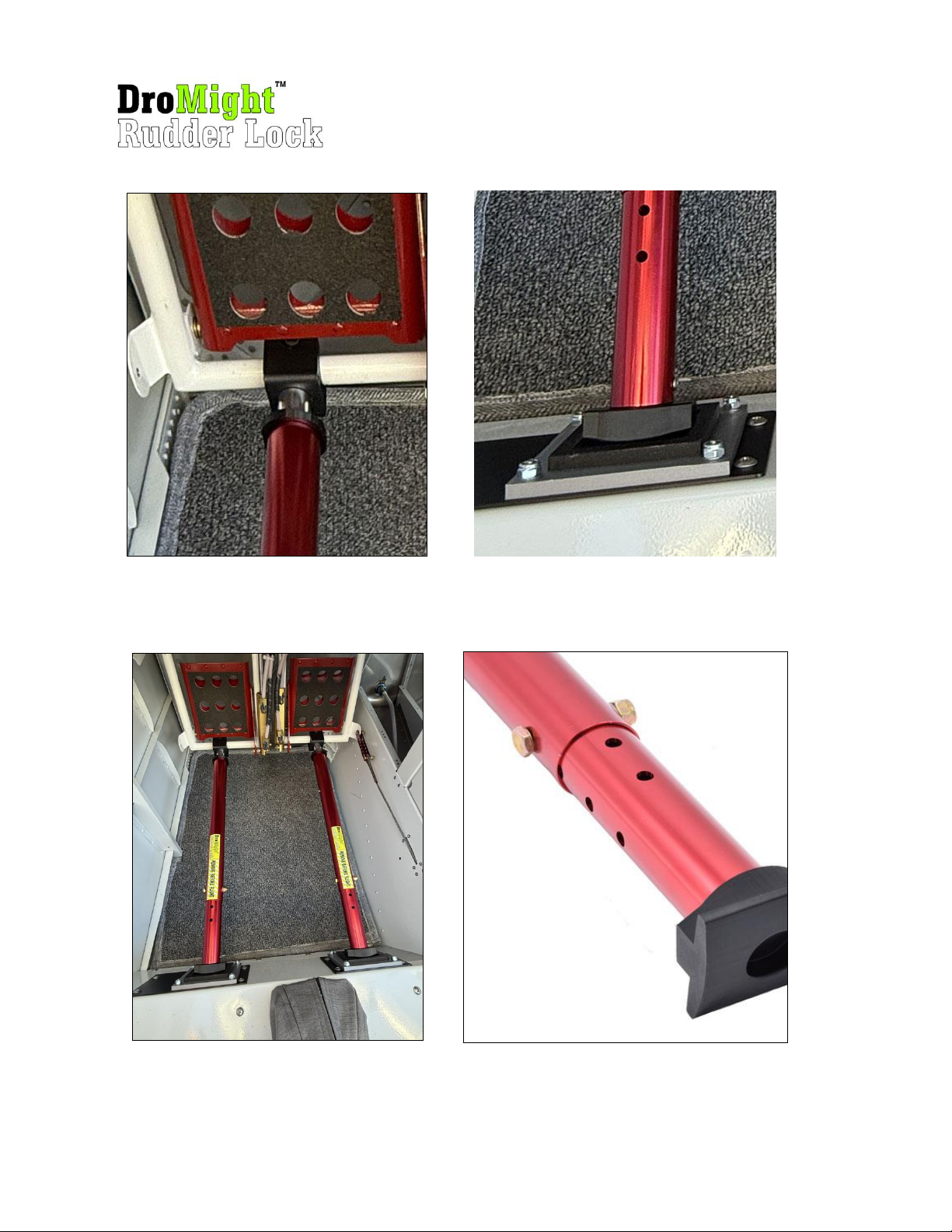
Figure 1: Rudder Lock Tip Installation
Figure 2: Rudder Lock Base Installation
Figure 3: Proper Installation
Figure 4: Length Adjustment Bolt
Page 6
Page 7
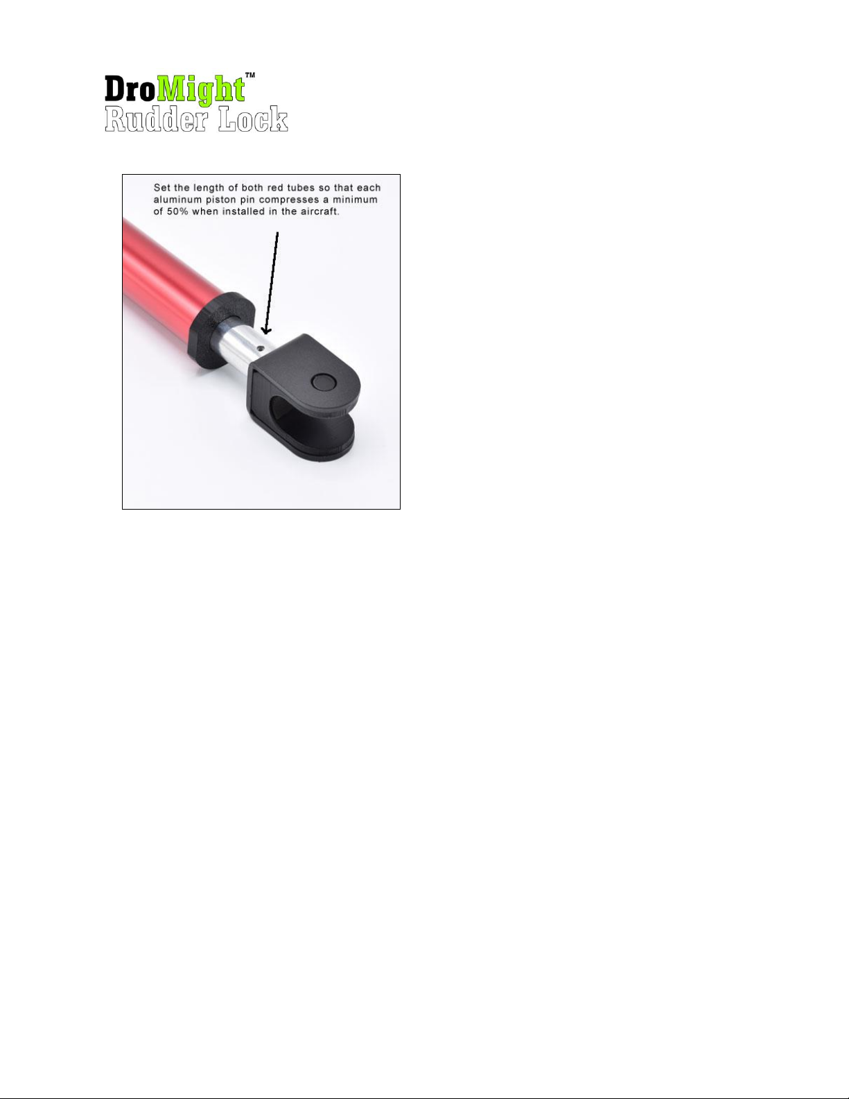
Figure 5. Tube Length Requirement
Page 7
Page 8

Removing the Red Rudder Locking Tubes.
The red rudder locking tubes can easily be removed by holding one of the tubes and gently pushing it
forward towards the rudder. The built in tension spring will compress and release the tube from its base
plate. Once the first red tube is removed, the second tube will no longer be under tension and can be
easily removed. After removal, place both red tubes in a carry bag and safely stow.
Extending the Rudder Lock Length
You might have the need to extend the length of the red rudder locking tubes in order to fit your
particular aircraft. The Vans RV-14 build plans show the proper method for installing the rudder pedals
into the bearing blocks. There are three possible builder configurations for the permanent installation
of your rudder pedals: closest to the firewall, closest to the pilot, and in the middle. In addition, it is
possible that your rudder pedals default placement is affected by how you rig the rudder pedal cables.
These factors affect how far the rudder pedals will be from the base plates installed on the control
column cover. For these reasons, we have designed the DroMightTM Rudder Lock so that the length can
easily be adjusted by the user. To lengthen or shorten the red tubes, remove the bolt shown in Figure 4.
Adjust the length as needed by sliding the smaller tube into the outer tube. Reinstall the bolt through a
set of pre-drilled holes that will give the desired length. Pre-drilled holes are spaced 20mm apart. If you
need smaller adjustments, you can rotate the inner tube 90 degrees and use the second row of holes.
This will give you a maximum of 10mm of adjustment. If you cannot find the perfect length using the
pre drilled holes, you can always custom drill a new set of holes to suit your needs.
Important tip: When setting your rudder tube length, it is very important that each aluminum piston
pin compresses a minimum of 50% when installed in the aircraft (see figure 5). Failure to do so could
result in the tubes not seating properly and falling out of their bases. You can confirm the 50%
compression requirement by making a mark with a sharpie pen in the middle of each aluminum piston
prior to installation. Then, install both red locking tubes and confirm that the marks you made have
disappeared into the black shoulder at the end of the red tube, or is at the very edge of the black
shoulder. Both tubes should always be the exact same length.
Disclaimer
While we are very confident that the DroMight Rudder lock is the most secure rudder locking system
that you can purchase, many damaging effects can happen to your rudder in high winds even while the
rudder lock is in place. If you anticipate that your aircraft will be subject to high winds, we recommend
that you use multiple locking methods to reduce the chance of damage. When high windows are
forecasted, it is always best to relocate your aircraft to an area where the winds are calmer or seek
shelter in a hangar. When in doubt, always refer to the manufacturers recommendations for keeping
your aircraft safe and airworthy. Using this rudder locking system in your airplane is confirmation that
you agree to assume the responsibility associated with the use of the device.
Page 8
Page 9

Warranty
Manufacturer warrants that the DroMightTM Rudder Lock system conform to Manufacturer’s
specifications and are free from defects in material and workmanship. Unless otherwise
specified by manufacturer in writing, this warranty extends for two years from the date of
original purchase. All warranties apply only to the original Purchaser unless otherwise agreed
by Seller and manufacturer in writing. Manufacturer’s sole obligation and Purchaser’s exclusive
remedy for any justified claim under this warranty shall be limited to one of the following, at
Manufacturer’s sole discretion: (a) repair or replacement of the Product or (b) a credit for the
price paid by the original Purchaser of the Product. This express warranty does not apply to,
and no warranty remedy will be given for, Product issues resulting from (a) accident, acts of
nature, improper installation, improper assembly, unreasonable or improper use, lack of proper
maintenance, unauthorized repairs or modifications, abuse, normal wear, or other causes not
directly arising from defects in materials or workmanship; (b) use of this product in any way
that is deemed illegal; (c) use of this product for military purposes; (d) any Product damaged by
the failure of the owner to use, maintain, or store the Product as specified in any applicable
instructions and/or warnings provided by Seller or the manufacturer. EXCEPT FOR LIMITED
WARRANTY SET FORTH ABOVE, SELLER MAKES NO WARRANTY WHATSOEVER, EXPRESS OR
IMPLIED, INCLUDING ANY WARRANTY OF MERCHANTABILITY, FITNESS FOR A PARTICULAR
PURPOSE OR AGAINST INFRINGEMENT. IN THE EVENT WARRANTIES EXIST AT LAW THAT MAY
NOT BE DISCLAIMED, PURCHASER AGREES THAT SUCH WARRANTIES SHALL BE LIMITED IN
DURATION TO THE TWO YEAR WARRANTY PERIOD AND TO THE REPLACEMENT VALUE OF THE
PRODUCT.
Page 9
 Loading...