

Page 1
BRUSHLESS
SPEED KIT
INSTALLATION INSTRUCTIONS
REQUIRED TOOLS
The following items are needed to install your Speed Kit.
✔ Phillips head screw driver
✔ 3/16" nut driver
✔ 1.5mm hex wrench
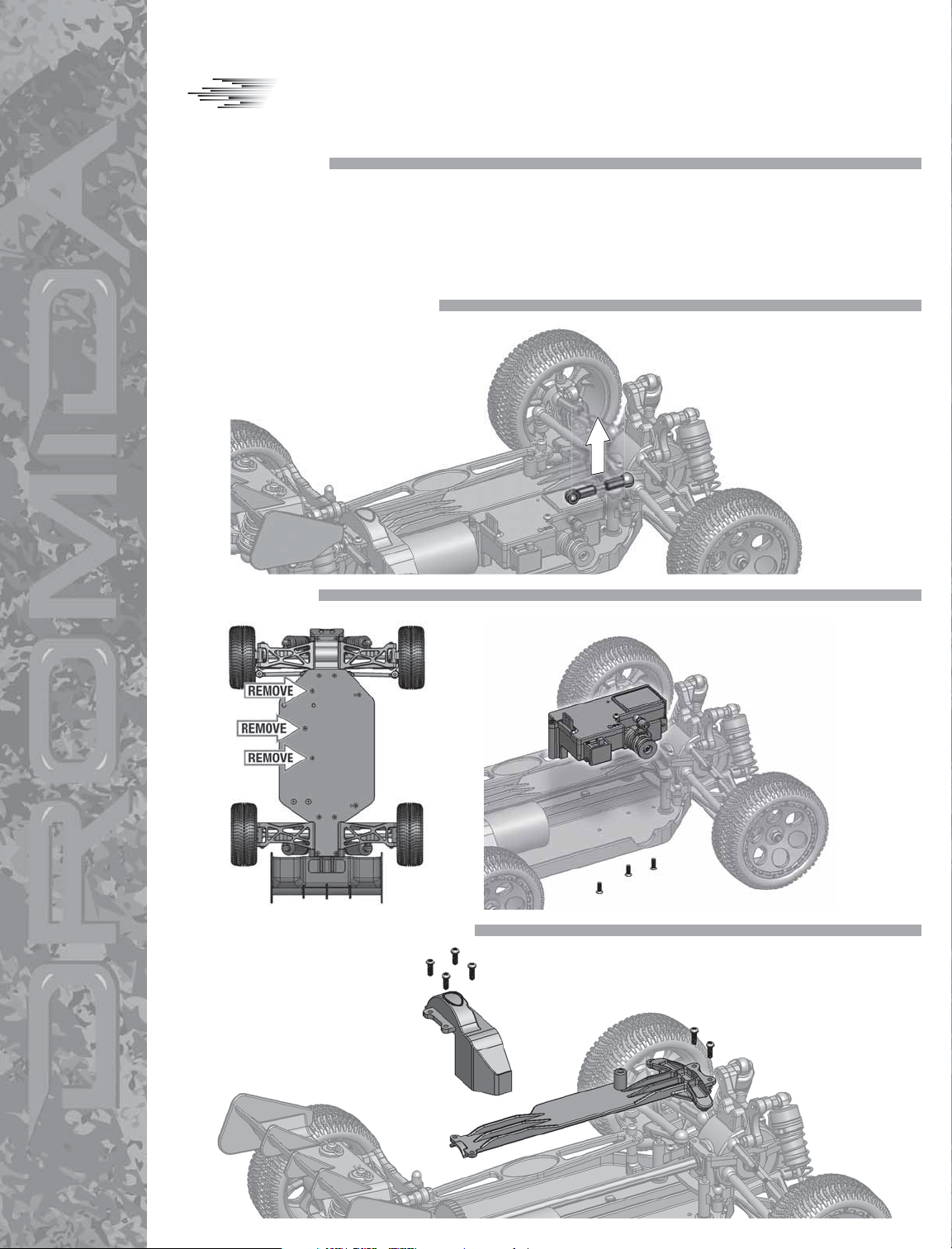
1. REMOVE STEERING LINKAGE
Using needlenose pliers, remove
the steering linkage from the
servo and the steering bellcrank.
✔ 2mm hex wrench
✔ 2.5mm hex wrench
✔ Needlenose pliers
Thank you for purchasing the Dromida Brushless
Speed Kit. It is strongly recommended to completely
read this manual before use. Damage resulting from
misuse or modification will void your warranty.
✔ Double sided servo tape (DTXR1215)
2. REMOVE 2N1
Remove the 2N1 assembly
from the chassis.
3. REMOVE UPPER CHASSIS BRACE
Remove the upper chassis
brace and spur gear cover
from the chassis.
Unplug motor connector.
Remove antenna tube
from mount and slide
antenna through upper
chassis brace. Carefully
cut the tie wrap making
sure no wires are cut.
Page 2
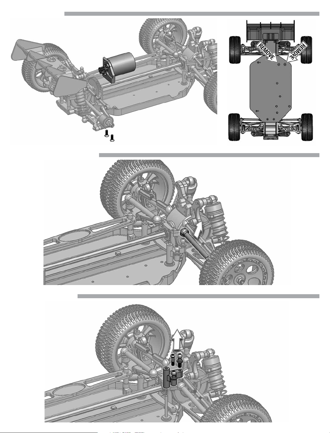
4. REMOVE MOTOR
Remove the motor assembly from the chassis.
Remove the set screw from the pinion for use later.
5. REMOVE RIGHT SIDE TIE ROD
Remove the motor mount from
the motor. Save the washers.
6. REMOVE BELLCRANK
Remove the right side tie rod
from the bellcrank.
Remove the screw and then slide
the right side steering bellcrank
off of the shaft. Remove the ball
stud from bellcrank for use later.
Page 3

7. INSTALL NEW BELLCRANK
Slide the bellcrank onto the shaft. Attach the
steering drag link using the screw removed
in step 6. Install the ball stud removed in
step 6. Snap the tie rod end that was
removed in step 5 onto the bellcrank.
8. INSTALLING BRUSHLESS MOTOR
Install the pinion onto the motor using the set screw removed in step 4. Make sure
that the pinion set screw seats on the fl at side. Using the washers removed in step
4 and motor screws supplied in the brushless speed kit, attach the brushless motor
to the motor mount. Note that the longer screw is used on the bottom as the motor
mount is thicker. Do not fully tighten the motor mounting screws at this time.
9. INSTALL MOTOR ASSEMBLY
NOTE! The included pinions
must be used as follows:
MT4.18: 12T pinion
SC4.18: 13T pinion
BX4.18: 13T pinion
Install the brushless speed kit motor assembly. Make sure the pinion
gear does not protrude past the spur gear. Set the gear mesh so that
there is a slight “rock” between the spur and pinion gears. Once the gear
mesh is set, tighten the motor mounting screws.
Page 4

10. RE-INSTALL SPUR GEAR COVER AND BRACE
Re-install the motor guard and upper chassis brace.
11. SERVO ASSEMBLY INSTALLATION
Remove the servo from the 2N1 unit.
Install the servo mount and servo to
the chassis using original screws.
Make sure that the
bellcrank shafts remain
seated in the chassis.
12. STEERING LINKAGE
Install the brushless speed kit steering
linkage by snapping it onto the balls.
Page 5

13. ESC INSTALLATION
Clean both the bottom of ESC and chassis with
alcohol. Using double sided tape, attach ESC to
chassis as shown. Connect the ESC to the motor.
Refer to the ESC instructions for setting up ESC.
14. RECEIVER INSTALLATION
Clean both the bottom of the receiver and the chassis brace with
alcohol. Install the receiver onto the upper chassis brace using
double-sided tape. Plug ESC into CH2 and servo into CH1 of the
receiver. Route the antenna wire through the antenna mount and
reinstall the antenna tube.
15. BINDING PROCEDURE
The receiver included with the Brushless Speed Kit is designed to work with the Dromida
D100 transmitter. The receiver MUST be bound to the transmitter before running the vehicle.
1. Turn on the transmitter.
2. Turn on the receiver.
3. Press and release the “BIND” button on the receiver.
At this point, the receiver should be bound to the transmitter.
16. TRIMMING
Throttle Trim
• If the vehicle rolls forward without throttle input, rotate the throttle trim knob slightly left.
• If the vehicle rolls backwards without throttle input, rotate the throttle trim knob slightly right.
Steering Trim
• If the vehicle tracks right (when viewed from behind), rotate the steering trim knob slightly left.
• If the vehicle tracks left (when viewed from behind), rotate the steering trim knob slightly right.
• Check that the servo saver screw is fully tightened to ensure that your vehicle tracks straight.
DIDC1150 v1.0 © 2014 DROMIDA, A HOBBICO COMPANY
We try very hard to have accurate and up-to-date information in this document. Any errors are unintentional.
dromida.com
 Loading...