

Page 1

HELPFUL HINTS
✔ Avoid working over a deep pile carpet. If you drop a small part or screw,
it may be diffi cult to fi nd.
✔ Place a mat or towel over your work area. This will prevent parts from rolling off and will protect the work surface.
✔ Avoid running the car in cold weather. The plastic and metal parts can become brittle at low temperatures.
In addition, grease and oil become thick, causing premature wear and poor performance.
MAINTENANCE
BEFORE EACH RUN
✔ IMPORTANT:
Check to make sure that
all screws are tight. Check that the servo
saver screw is fully tightened to ensure that
your Dromida DT4.18BL tracks straight.
✔ Always check the condition of your
radio system batteries and replace if
necessary.
✔ Check to make sure that all of the
moving parts of the Dromida DT4.18BL
move freely and do not bind.
✔ Turn on the radio and make sure the
servo moves easily and in the proper
direction.
✔
Check for any broken or damaged
parts. Replace them before running the
Dromida DT4.18BL. Running the Dromida
DT4.18BL with broken or damaged parts
could damage additional parts.
✔ Check to make sure that all wires are
properly connected.
AFTER EACH RUN
✔ Clean any debris from the chassis and
moving parts.
✔ Check for any broken or damaged parts.
Replace them before the next run.
✔ Disconnect and remove the battery
from the chassis.
AFTER EVERY 10 RUNS
✔ Check to make sure that the bearings
are free of dirt and debris, and roll
smoothly.
✔ Check the shocks for oil leakage.
✔ Check the tires to make sure they are
still properly glued to the rims.
ASSEMBLY AND MAINTENANCE GUIDE
HARDWARE CHART
2x10MM FLAT HEAD SCREW
H
2x14MM FLAT HEAD SCREW
J
2.5x8MM FLAT HEAD SCREW
K
2.5x8MM SOCKET HEAD SCREW
L
2.5x10MM SOCKET
HEAD SCREW
Z
2.5x14MM SOCKET HEAD CAP SCREW
M
2.5x6MM SOCKET HEAD SCREW
N
2x8MM ROUND HEAD
SHOULDER SCREW
P
3x3MM SET SCREW
Q
3MM LOCK NUT
R
4MM NUT
FF
1.5x6MM E-CLIP
U
2.6x5MM WASHER
S
BODY CLIP (SMALL
)
V
2x6MM SELF-TAPPING
ROUND HEAD SCREW
X
2x4MM ROUND HEAD SCREW
C
2x8MM FLAT HEAD SCREW
G
2x8MM ROUND HEAD SCREW
E
2x10MM ROUND HEAD SCREW
F
6x10MM BALL BEARING
A
8x12MM BALL BEARING
B
2x20MM ROUND
HEAD SCREW
EE
3x8MM SELF-TAPPING
BUTTON HEAD SCREW
DD
2.5x5MM BUTTON HEAD
SCREW
BB
ACTUAL SIZE
(
WHEN PRINTED AT 100%
)
™
Page 2
31
33
32
33
30
32
G
G
B
G
G
B
34
GREASE
GREASE
GREASE
GREASE
NOTE DIRECTION
NOTE DIRECTION
2
2
1
H
H
H
H
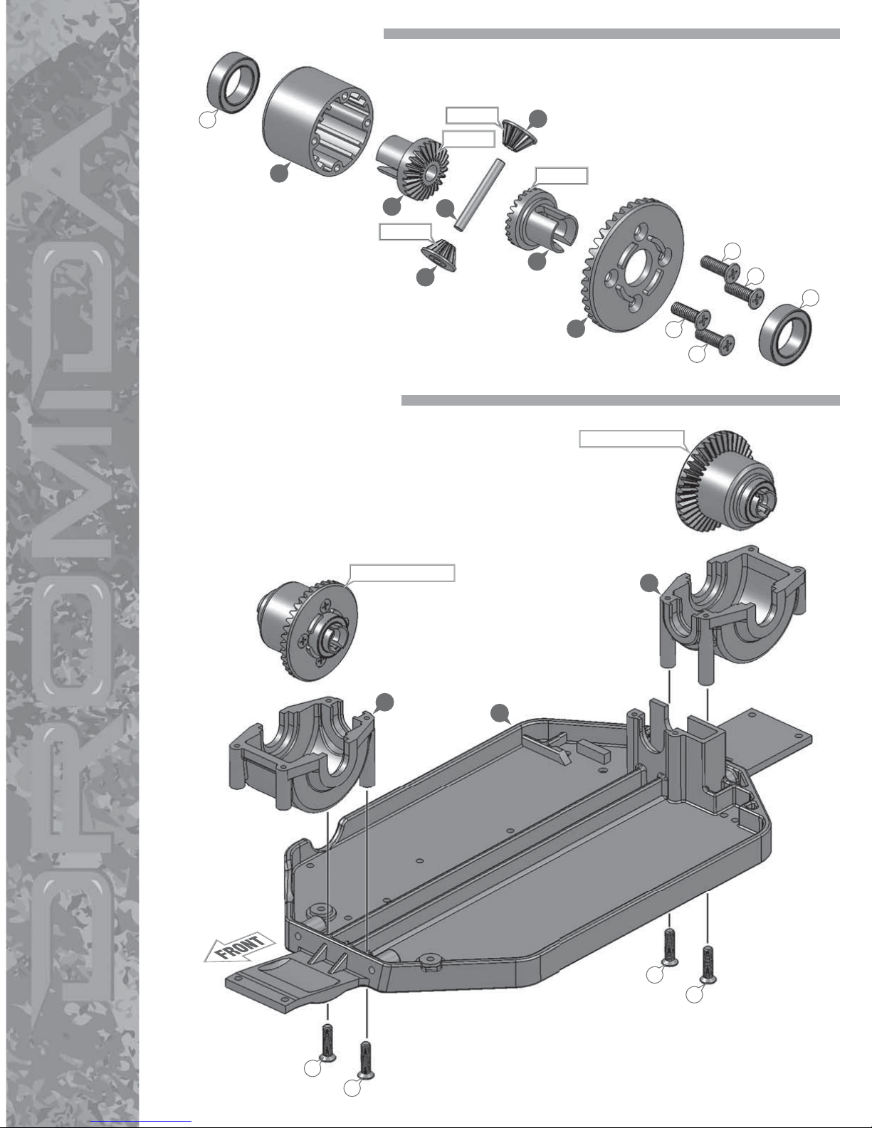
1. DIFFERENTIAL ASSEMBLY
2. DIFFERENTIALS TO CHASSIS
Page 3
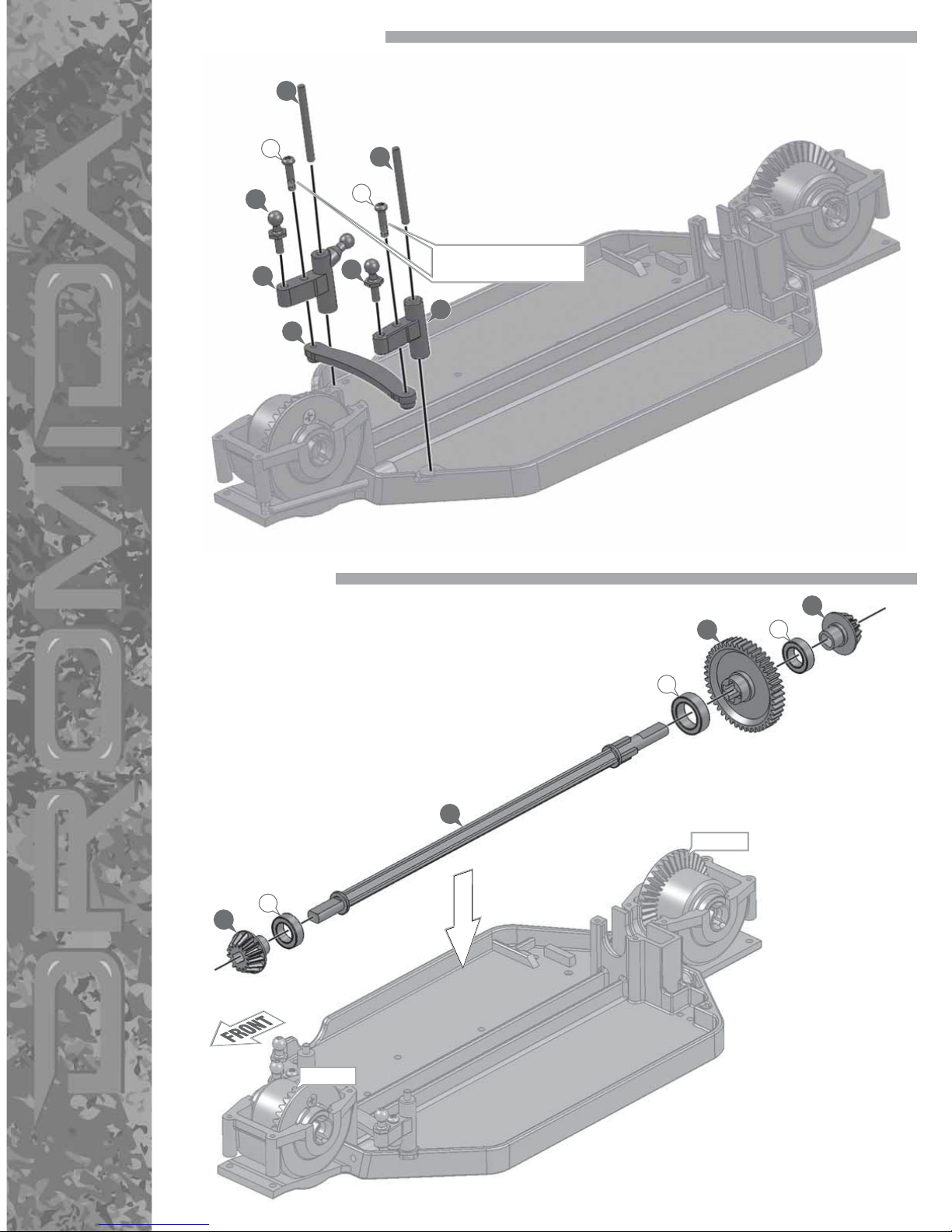
3. STEERING ASSEMBLY
4. CENTER SHAFT
45
40
18
18
44
40
46
P
P
DO NOT OVERTIGHTEN
(
WILL CAUSE BINDING
)
28
29
27
28
A
B
A
GREASE
GREASE
Page 4
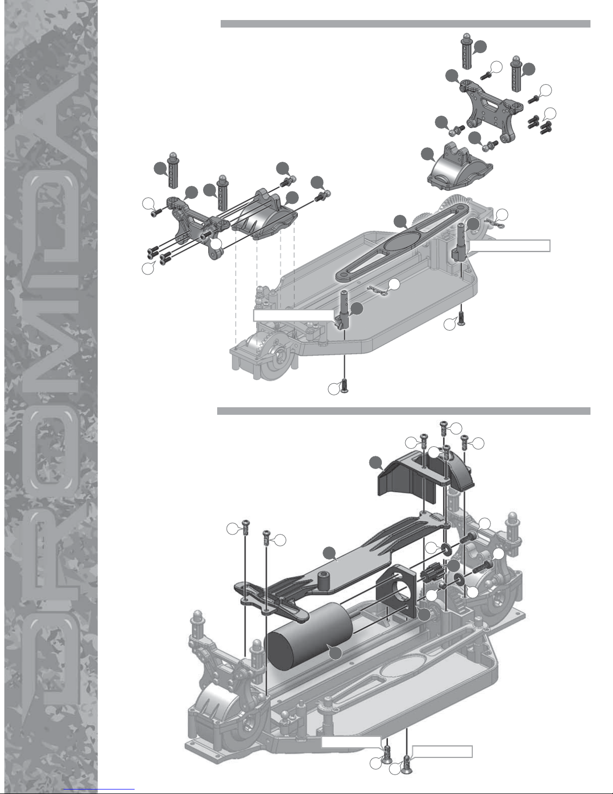
5. SHOCK TOWERS
6. MOTOR MOUNT
7
3
8
71
12
8
40
3
7
40
40
40
11
8
8
G
G
E
E
E
V
V
E
E
E
NOTE DIFFERENCE
NOTE DIFFERENCE
L
N
S
K
Q
K
S
E
E
E
E
E
E
39
26
4
25
24
THREADLOCK
THREADLOCK
Page 5
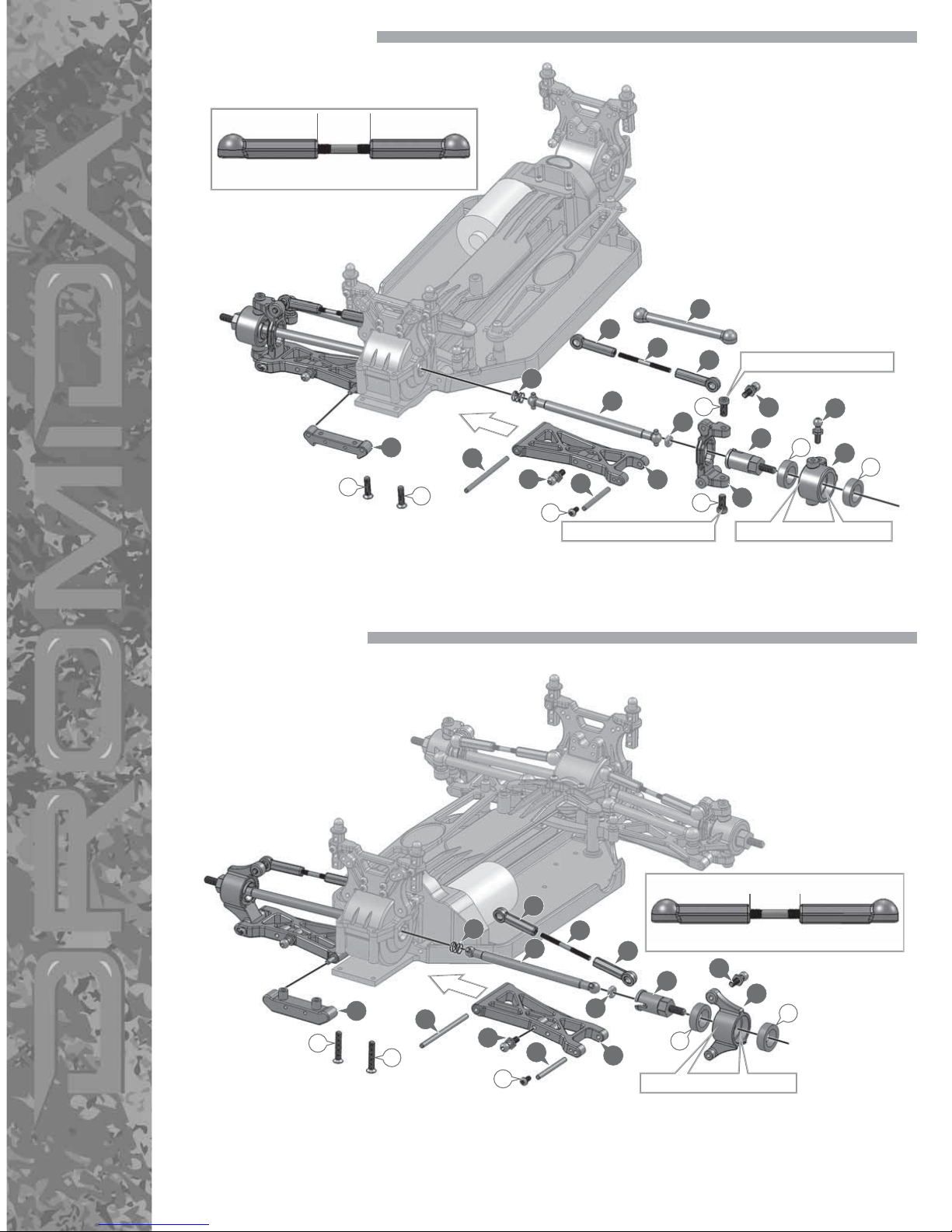
7. FRONT SUSPENSION
8. REAR SUSPENSION
41
42
41
43
38
15
40
36
35
37
17
18
B
B
DO NOT OVERTIGHTEN FULLY SEAT BEARINGS
DO NOT OVERTIGHTEN
9
40
L
L
C
H
40
13
14
H
ACTUAL SIZE
11.2
MM
41
42
41
38
16
36
35
17
40
18
B
FULLY SEAT BEARINGS
10
40
C
J
13
J
37
B
10.75MM
ACTUAL SIZE
Page 6
G
G
5
48
DOUBLE-SIDED TAPE
DOUBLE-SIDED TAPE
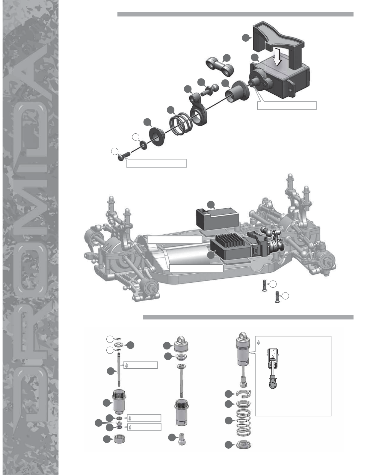
9. RADIO BOX
10. SHOCK ASSEMBLY
47
51
52
50
40
49
93
6
F
S
SCREW MUST BE SNUG
CENTER SERVO FIRST
SHOCK OIL
SHOCK OIL
SHOCK OIL
58
55
62
62
59
66
60
56
69
64
68
65
63
U
U
61
SHOCK OIL
1. Completely fill the
shock body with
shock oil.
2. Slowly move the
shaft up and down
to remove bubbles.
3. Slowly tighten the shock cap
onto the shock body to allow
any remaining air to escape.
Page 7
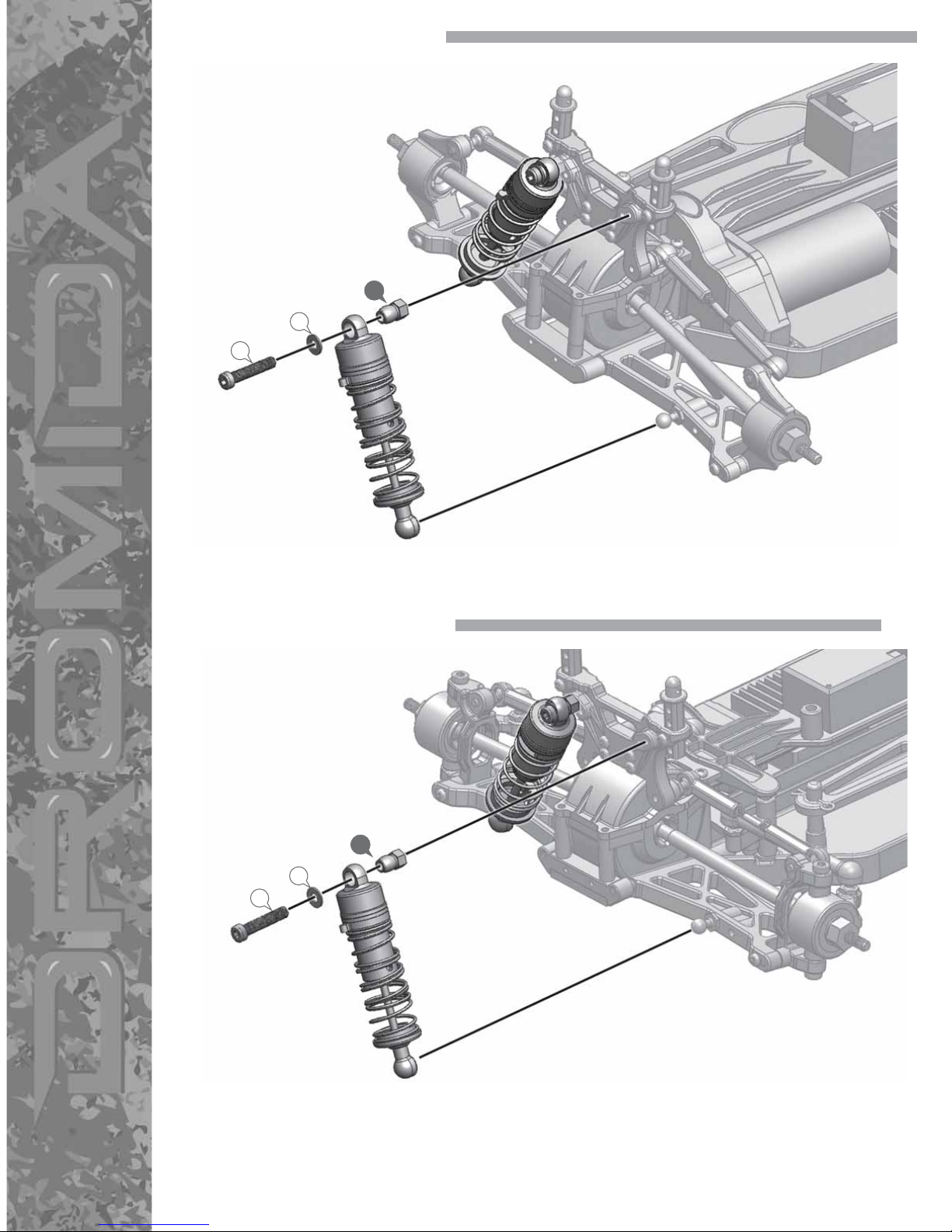
11. REAR SHOCK INSTALLATION
12. FRONT SHOCK INSTALLATION
53
S
M
53
S
M
Page 8

13. FRONT BUMPER
14. SPARE TIRE RACK
19
20
E
E
E
E
E
E
74
BB
BB
BB
BB
23
E
E
E
E
22
Page 9

15. WHEELS
16. ROLL BAR
70
70
70
R
DD
72
73
R
75
76
77
77
84
FF
FF
FF
FF
FF
FF
FF
FF
79
92
79
EE
EE
F
F
78
Page 10

BRUSHLESS ESC
•
Always monitor ESC, motor and battery temperatures during running.
•
Disconnect the battery from the ESC immediately if the ESC or battery becomes hot. Allow the ESC or battery
to cool completely before reconnecting.
•
Never use more than a 2S LiPo or 7-cell NiMH battery.
•
Always disconnect the battery from the ESC when not in use.
•
Make sure the battery is fully charged before connecting to the ESC.
•
Do not attempt to use the brushless ESC with a brushed motor.
•
The ESC may become hot during running. Allow the ESC to cool before touching.
•
Never turn on the ESC before plugging it into the receiver and switching on the transmitter.
•
Dromida is not responsible for incidental damage or personal injury as a result of misuse of this product.
THROTTLE CALIBRATION
Before the ESC can be used, throttle calibration must be performed to ensure the throttle is set up properly. Be
sure that your throttle trim is set to ZERO before performing calibration and that throttle end points and dual rates
are set to maximum.
Note: We recommend that you prop the vehicle up off the ground to prevent it from driving off the surface in case
the calibration is not performed properly.
1. With the ESC turned off, turn on the transmitter.
2. Press and hold the “SET” button on the on/off switch. Then, switch on the ESC.
When the red LED begins to flash, release the button immediately.
3. With the transmitter throttle at neutral, press and release the ESC
“SET” button. The green LED should flash one time.
4. With the transmitter throttle at full throttle, press and release the ESC
“SET” button. The green LED should flash two times.
5. With the transmitter throttle at full reverse, press and release the ESC
“SET” button. The green LED should flash three times.
6. After the calibration is completed, wait at least three seconds before giving any transmitter input.
NOTE: If you do not release the “SET” button once the red LED begins to flash, the ESC will enter the program
mode. If this happens turn the ESC off and start over.
LED STATUS IN NORMAL RUNNING
•
When the throttle is at neutral, all LEDs should be off.
•
When running forward, the red LED will illuminate.
•
At full throttle, the Red and Green LEDs will illuminate.
•
During braking, the red LED will flash quickly.
ALERT TONES
When you turn on the ESC it checks the battery’s voltage. If the battery is out of the normal voltage range it will
alert you with a “beep-beep….beep-beep….beep-beep.”
If the throttle signal is abnormal it will alert with a “beep………beep……..beep.”
VOLTAGE PROTECTION
The Dromida brushless ESC is equipped with a “LVC” (Low Voltage Cut-off) to protect LiPo batteries from being
drained too low. If the LiPo battery is lower than the designated cut-off for more than 2 seconds the ESC will cut
off the output power. The ESC cannot be restarted if the voltage of each LiPo cell is lower than 3.5V. If using a
non-LiPo pack, be sure to adjust the ESC to its No-Cutoff Option ("No LVC") to maximize run time.
OVERHEAT PROTECTION
If the temperature of the ESC is over the factory preset temperature for 5 seconds, the ESC will cut off the output
power. If this happens, check for binding or broken parts on the vehicle.
THROTTLE SIGNAL LOSS PROTECTION
The ESC will cut off the output power if the throttle signal from the transmitter is lost for 0.2 seconds.
Page 11

PROGRAMMING
Running Mode: This function adjusts the running mode between forward/brake and forward/brake/reverse.
Drag Brake Force: This function adjusts the amount of drag brake applied at neutral throttle to simulate a slight
braking effect of a neutral brushed motor while coasting.
Low Voltage Cut-Off (LVC): This program is used to prevent the LiPo battery from over-discharging. The ESC
monitors the battery’s voltage. At any time, if the battery’s voltage is lower than the designated value, the output
power will be reduced to 50%. After 10 seconds the ESC will cut the motor power off.
Start Mode (Punch): This function adjusts the amount of initial power when the trigger is applied.
Maximum Brake Force: This program adjusts the amount of overall brake force applied when at full brake.
During programming the ESC the motor will emit a “beep” tone at the same time the LED flashes. A long time
flash and long “beep” represents “5” so it is easy to identify items with large numbers.
For example:
A long time flash (motor sounds “beeeep”) equals a value of 5.
A long time flash + 1 short flash (motor sounds “beeeep-beep”) equals a value of 6.
A long time flash + 2 short flashes (motor sounds “beeeep-beep-beep”) equals a value of 7.
ESC OFF
Turn on Tx
TO COMPLETE PROGRAMMING, SWITCH OFF THE ESC, AND THEN SWITCH IT ON
To adjust RUNNING MODE,
release SET button.
To adjust the value in the mode, press the SET button until the
desired value is reached.
Hold SET button
for 6 SECONDS
Hold SET button
for 9 SECONDS
Hold SET button
for 12 SECONDS
Hold SET button
for 15 SECONDS
Hold SET button
for 18 SECONDS
To adjust DRAG BRAKE FORCE,
release SET button.
To adjust LVC,
release SET button.
To adjust PUNCH,
release SET button.
To adjust MAX BRAKE FORCE,
release SET button.
Hold SET Button
Switch on ESC
Red LED Flashes
Red LED Flashes 1 TIME = FORWARD/BRAKE
Red LED Flashes 2 TIMES = FORWARD/BRAKE/REVERSE
Red LED Flashes 1 TIME = SOFT Initial Start
Red LED Flashes 2 TIMES = NORMAL Initial Start
Red LED Flashes 3 TIMES = AGGRESSIVE Initial Start
Red LED Flashes 4 TIMES = VERY AGGRESSIVE Initial Start
Red LED Flashes 1 TIME = SOFT Brake Force
Red LED Flashes 2 TIMES = NORMAL Brake Force
Red LED Flashes 3 TIMES = AGGRESSIVE Brake Force
Red LED Flashes 4 TIMES = VERY AGGRESSIVE Brake Force
Red LED Flashes 1 TIME =
NO
LVC
Red LED Flashes 2 TIMES = 2.6V LVC
Red LED Flashes 3 TIMES = 2.8V LVC
Red LED Flashes 4 TIMES = 3.0V LVC
Red LED Flashes 5 TIMES = 3.2V LVC
Red LED Flashes 6 TIMES = 3.4V LVC
Red LED Flashes 1 TIME = 0% Drag Force
Red LED Flashes 2 TIMES = 5% Drag Force
Red LED Flashes 3 TIMES = 10% Drag Force
Red LED Flashes 4 TIMES = 15% Drag Force
Red LED Flashes 5 TIMES = 20% Drag Force
Red LED Flashes 6 TIMES = 25% Drag Force
Red LED Flashes 7 TIMES = 30% Drag Force
Red LED Flashes 8 TIMES = 40% Drag Force
RUNNING MODE
Green LED Flashes 1 TIME
DRAG BRAKE FORCE
Green LED Flashes 2 TIMES
LOW VOLTAGE CUTOFF (LVC)
Green LED Flashes 3 TIMES
START MODE (PUNCH)
Green LED Flashes 4 TIMES
MAX BRAKE FORCE
Green LED Flashes 5 TIMES
To reset to the factory default settings, set the throttle to neutral and hold the “SET” button for 3 seconds. The red and
green LED will slowly flash at the same time to indicate the ESC has been restored to the factory default settings.
Page 12
When tuning the Dromida DT4.18BL make sure that you have equal lengths from one side to the other on the
shocks and upper rods. Also, make sure to have the shock pre-load adjusters at the same setting from left to right.
They do not have to be the same front to rear.
PINIONS
The Dromida DT4.18BL comes stock with the 12 tooth pinion. To obtain higher top speeds you can install a larger
pinion gear onto the motor. This will, however, decrease your acceleration and run time. TIP: Smaller pinion equals
more torque, less top speed. Larger pinion equals more top speed, less torque.
SHOCK OIL
The Dromida DT4.18BL comes stock with 30 weight oil in the shocks. The handling can be tuned by changing the
shock oil to either heavier (bigger number) or lighter (smaller number). By putting heavier oil in the shocks, the
car will have less chassis roll and become more responsive. Putting lighter oil in the shocks will cause the car to
be less responsive and have more chassis roll. For smooth, high traction surfaces, a thicker oil would be best. For
low traction or bumpy surfaces, a lighter oil would be best.
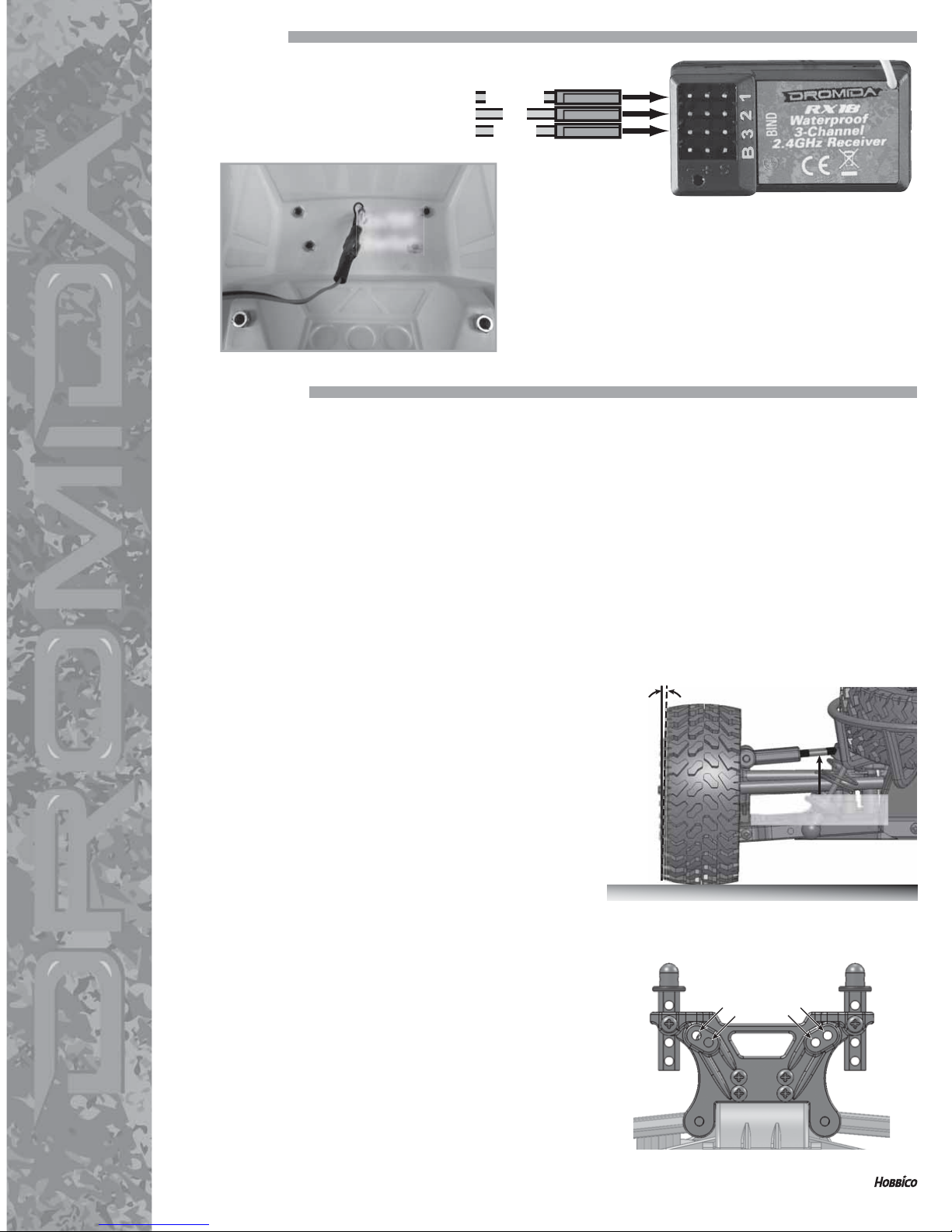
CAMBER
Camber refers to the angle at which the tire and wheel ride
in relation to the ground when viewed from the front or rear.
Negative camber is when the wheels lean inward and positive
camber is when the wheels lean outward. Usually adding
a small amount of negative camber (0° to -2°) will increase
traction. However, adding too much camber will decrease
traction. The objective is to keep as much of the tire as possible
in contact with the running surface. Never put in positive
camber. Make sure that both sides are equal.
SHOCK SPRINGS
For low traction or bumpy surfaces, a softer spring should be used. For high traction or smooth surfaces, a fi rmer
spring should be used.
FRONT SHOCK ADJUSTMENT
Moving the tops of the shocks out (A) will increase steering
reaction but decrease front traction. Moving the tops of the
shocks in (B) will result in slower steering reaction but will be
smoother over bumps and have more front traction.
REAR SHOCK ADJUSTMENT
Moving the tops of the shocks out (A) will increase steering
reaction and decrease rear traction. Moving the tops of the
shocks in (B) will result in slower steering reaction but will be
smoother over bumps and have more rear traction.
TUNING GUIDE
A
AA
BB
ADJUST LENGTH TO
CHANGE THE CAMBER
2˚ NEGATIVE CAMBER
We try very hard to have accurate and up-to-date information in this document. Any errors are unintentional.
dromida.com
DIDC0056 v1.0 © 2015 DROMIDA, A HOBBICO COMPANY
LED LIGHTS
Make sure when you plug your LED
lights into Channel 3 of the receiver.
To turn the LED lights on, switch the on/off switch to the on
position. To make sure you do not leave your Dromida LED
lights on when not running your kit, you should dissconnect
the battery after every run.
ESC
LIGHTS
STEERING
On/Off
Switch
 Loading...