

Page 1
INSTALLATION MANUAL
ECO-55 / ECO-55 ST
(DP00070 & DP00071 model)
Safety tested according to ULC S627,UL1482 and
ASTM E1509 by an accredited laboratory
INSTALLATION BY A PROFESSIONAL
IS STRONGLY RECOMMENDED
Stove Builder International inc.
250, rue de Copenhague,
St-Augustin-de-Desmaures (Québec) Canada
G3A 2H3
CONTACT LOCAL BUILDING OR FIRE OFFICIALS ABOUT RESTRICTIONS AND INSTALLATION
INSPECTION REQUIREMENTS IN YOUR AREA.
PLEASE READ THIS ENTIRE MANUAL BEFORE INSTALLATION AND USE OF THIS PELLET FUELBURNING ROOM HEATER. FAILURE TO FOLLOW THESE INSTRUCTIONS COULD RESULT IN
PROPERTY DAMAGE, BODILY INJURY OR EVEN DEATH.
READ AND KEEP THIS MANUAL FOR REFERENCE
This manual is available for free download on the manufacturer’s website. It is a copyrighted document. Re-sale
is strictly prohibited. The manufacturer may update this manual from time to time and cannot be responsible
for problems, injuries, or damages arising out of the use of information contained in any manual obtained from
unauthorized sources.
Printed in Canada 45876IA-2017-02-07
Customer service : 418-908-8002
Email : tech@sbi-international.com
www.drolet.ca
Page 2
1. SAFETY INFORMATION
We highly recommend that our pellet burning hearth
products be installed and serviced by professionals
who are certied in the United States by NFI (National
Fireplace Institute ® ) or in Canada by WETT (Wood
Energy Technology Transfer) or in Quebec by APC
(Association des Professionnels du Chauffage).
If this appliance is not properly installed,
combustible materials near it may overheat. To
reduce the risk of re, follow the installation
instructions in this manual exactly. Contact local
building or re ofcials about restrictions and
installation inspection requirements in your area.
Please read this entire manual before you install and
use your new stove. You may need to get a building
permit for the installation of this appliance and the
venting system that it is connected to. Consult your
municipal building department or re department
before installation. We recommend that you also
inform your home insurance company to nd out if
the installation will affect your policy.
WARNING
THIS STOVE IS MOBILE HOME APPROVED
AND REQUIRES INSTALLATION OF A FRESH
AIR KIT, SOLD SEPARATELY. THE STOVE
MUST BE ATTACHED TO THE STRUCTURE OF
THE MOBILE HOME AND THE STRUCTURAL
INTEGRITY OF THE MOBILE HOME FLOOR,
WALL, AND CEILING / ROOF MUST BE
MAINTAINED. DO NOT INSTALL IN A SLEEPING
ROOM.
CAUTION
THIS STOVE MUST BE CONNECTED TO
A STANDARD 120V / 60HZ, GROUNDED
ELECTRICAL OUTLET. DO NOT USE AN
ADAPTER PLUG OR SEVER THE GROUNDING
PLUG. DO NOT ROUTE THE ELECTRICAL
CORD UNDERNEATH, IN FRONT OR OVER THE
STOVE.
WARNING
THIS STOVE IS NOT RECOMMENDED TO BE
INSTALLED IN A BEDROOM.
WARNING
IF THIS STOVE IS NOT PROPERLY INSTALLED,
A HOUSE FIRE MAY RESULT. TO REDUCE THE
RISK OF FIRE, FOLLOW THE INSTALLATION
INSTRUCTIONS.
WARNING
BURNING ANY SOLID FUELS GENERATES
CARBON MONOXIDE IN LOW
CONCENTRATION. THIS GAS IS EVACUATED
BY THE EXHAUST VENTING SYSTEM. IN
HIGHER CONCENTRATIONS, CARBON
MONOXIDE IS TOXIC AND MAY CAUSE DEATH.
TO PREVENT THIS, ENSURE THAT YOUR
EXHAUST VENTING SYSTEM IS AIRTIGHT.
NOTICE
Mixing of appliance components from different
sources or modifying components is prohibited
and will void the warranty. Any modication of the
appliance that has not been approved in writing by
the testing authority is prohibited and violates CSA
B365 (Canada) and NFPA 211 (USA).
NOTICE
When locating your appliance, make sure the vent
will not interfere with any truss, roof beams, wall
studs, water pipes or electrical wiring. It may be
easier to relocate appliance than to rework the
building structure.
NOTICE
The information given on the certication label
afxed to the stove always overrides the information
published in any other media (owner’s manual,
catalogues, yers, magazines or web sites).
Page 2 INSTALLATION MANUAL ECO-55/ECO-55ST
Page 3
NOTICE
This stove has been developed and built for
residential supplementary heat source. Commercial
and industrial use is prohibited and will void the
warranty.
NOTICE
Stove Builder International inc. (SBI) grants no
warranty, implied or stated, for the poor installation
of your appliance and assumes no responsibility of
any consequential damages.
Page 3INSTALLATION MANUAL ECO-55/ECO-55ST
Page 4

TABLE OF CONTENTS
1. SAFETY INFORMATION ................................................................................. 2
2. GENERAL FEATURES .................................................................................... 5
2.1 OVERALL DIMENSIONS (DP00070) ..................................................................................5
2.2 OVERALL DIMENSIONS (DP00071) ..................................................................................6
3. CLEARANCES TO COMBUSTIBLE MATERIALS .......................................... 7
3.1 CLEARANCES TO COMBUSTIBLES MATERIALS, WALLS AND CEILING .....................7
3.2 FLOOR PROTECTION ........................................................................................................8
4. VENTING SYSTEM .......................................................................................... 9
4.1 GENERAL ............................................................................................................................9
4.2 RECOMMANDATIONS ........................................................................................................9
4.3 EQUIVALENT VENT LENGTH (EVL) ..................................................................................9
4.3.1 RECOMMENDED EXHAUST VENTING DIAMETER .......................................................9
4.3.2 INSTALLATION COMPLIANCE ....................................................................................... 10
4.4 TERMINATION LOCATION ...............................................................................................11
4.5 DIRECT VENT SYSTEM ..................................................................................................12
4.6 INSTALLATION CONFIGURATION ...................................................................................12
4.6.1 THROUGH WALL INSTALLATION (MAIN FLOOR OR BASEMENT) ............................. 12
4.6.2 THROUGH ROOF INSTALLATION .................................................................................12
4.6.3 THROUGH A FACTORY BUILT CHIMNEY ....................................................................13
4.6.4 THROUGH AN EXISTING MASONRY FIREPLACE ......................................................13
4.6.5 THROUGH AN EXISTING MASONRY CHIMNEY ..........................................................14
5. INSTALLING THE OPTIONAL HOPPER EXTENSION ................................14
6. MOBILE HOME INSTALLATION ................................................................... 15
7. INSTALLING A THERMOSTAT ..................................................................... 15
7.1 THERMOSTAT LOCATION ................................................................................................15
7.2 WIRED THERMOSTAT ......................................................................................................16
7.3 WIRELESS THERMOSTAT ...............................................................................................16
8. COMBUSTION AIR SUPPLY ......................................................................... 16
8.1 SOURCES OF OUTSIDE COMBUSTION AIR ..................................................................17
9. APPLIANCE SET-UP ..................................................................................... 18
9.1 GENERAL ..........................................................................................................................18
10. WIRING DIAGRAM ...................................................................................... 19
11. EXPLODED VIEWS AND PARTS LIST DP00070 AND DP00071 .............. 20
Page 4 INSTALLATION MANUAL ECO-55/ECO-55ST
Page 5
2. GENERAL FEATURES
25 1/4"
640mm
22 7/8"
581mm
24 7/8"
632mm
29 1/2"
750mm
23 7/8"
607mm
24 7/8"
8 5/8"
218mm
17 3/8"
441mm
32 5/8"
829mm
O
3"
76mm
O
3"
76mm
11 3/8"
290mm
6 1/8"
155mm
A
B
A
B
15 3/4"
401mm
8 1/8"
205mm
23 7/8"
607mm
24 7/8"
633mm
8 5/8"
218mm
17 3/8"
441mm
32 5/8"
829mm
O
3"
76mm
O
3"
76mm
11 3/8"
290mm
6 1/8"
155mm
A
B
A
B
O
3"
76mm
O
3"
76mm
11 3/8"
290mm
6 1/8"
155mm
A
B
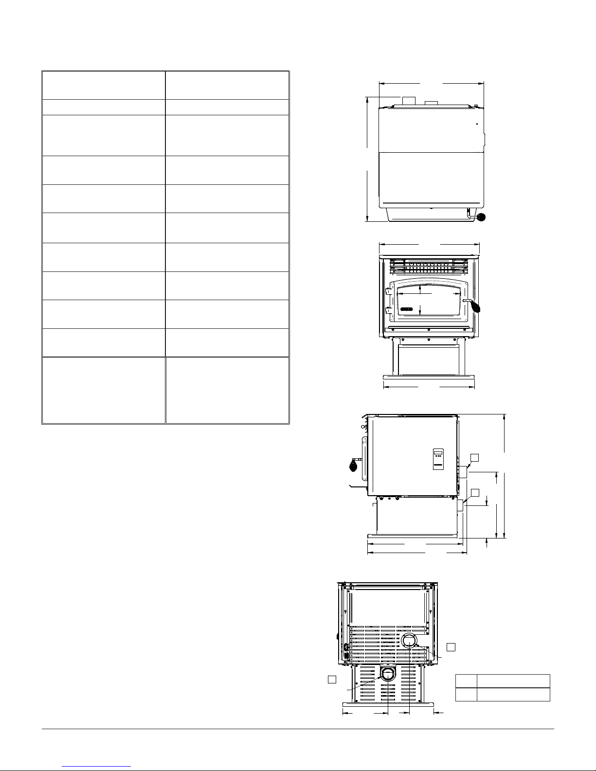
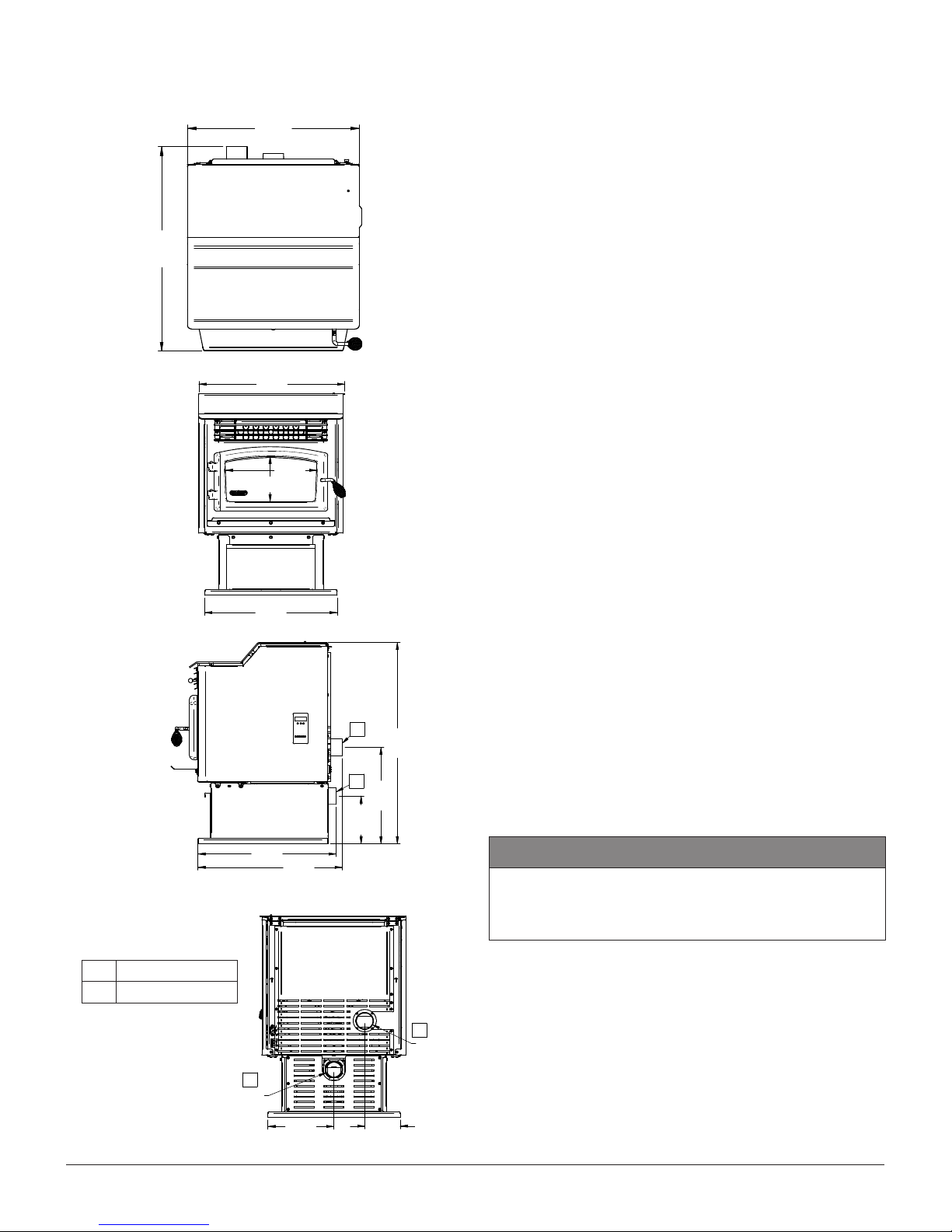
2.1 OVERALL DIMENSIONS (DP00070)
Recommended
3 in. (75mm)
chimney diameter
Flue outlet diameter 3 in. (75mm)
Type of chimney ULC/ORD-C441
CAN/ULC S609
UL 641 (TYPE L)
Approved for alcove
Yes
installation
Approved for mobile
Yes
home installation ‡
Shipping weight
(without option)
Appliance weight
(without option)
Particulate emission
standard
277 lb (DP00070)
286 lb (DP00071)
235 lb (DP00070)
242 lb (DP00071)
CSA B415.1-10
ASTM E2779
USA standard (safety) ASTM E1509
UL 1482
Canadian standard
ULC S627
(safety)
Electrical
requirements
Voltage and frequency
120VAC and 60Hz
24 7/8"
632mm
29 1/2"
750mm
Ignition : 3.02A
‡ Mobile home (Canada) or manufactured home (USA): The
US department of Housing and Urban Development describes
“manufactured homes” better known as “mobile homes” as
followed; buildings built on xed wheels and those transported on
temporary wheels/axles and set on a permanent foundation. In
Canada, a mobile home is a dwelling for which the manufacture
and assembly of each component is completed or substantially
completed prior to being moved to a site for installation on
a foundation and connection to service facilities and which
conforms to the CAN/CSA-Z240 MH standard.
A FRESH AIR INLET
B FLUE OUTLET
Page 5INSTALLATION MANUAL ECO-55/ECO-55ST
Page 6
2.2 OVERALL DIMENSIONS (DP00071)
23 7/8"
607mm
24 7/8"
633mm
8 5/8"
218mm
17 1/4"
439mm
36 1/8"
918mm
25 1/8"
639mm
22 7/8"
581mm
8 1/8"
205mm
15 3/4"
401mm
24 7/8"
632mm
29 1/2"
750mm
A
B
A
B
O
3"
76mm
O
3"
76mm
11 3/8"
290mm
6 1/8"
155mm
23 7/8"
607mm
24 7/8"
633mm
8 5/8"
218mm
17 1/4"
439mm
36 1/8"
918mm
A
B
A
B
O
3"
76mm
O
3"
76mm
11 3/8"
290mm
6 1/8"
155mm
A
B
O
3"
76mm
O
3"
76mm
11 3/8"
290mm
6 1/8"
155mm
24 7/8"
632mm
29 1/2"
750mm
2.3 REGULATIONS COVERING PELLET
STOVE INSTALLATION
When installed and operated as described in these
instructions, this pellet stove is suitable for use as a
freestanding heater in residential installations.
In Canada, the CSA B365 Installation Code for Solid
Fuel Burning Appliances and Equipment and the CSA
C22.1 Canadian National Electrical Code are to be
followed in the absence of local code requirements.
In the USA, the ANSI NFPA 211 Standard for
Chimneys, Fireplaces, Vents and Solid Fuel-Burning
Appliances and the ANSI NFPA 70 National Electrical
Code are to be followed in the absence of local code
requirements.
This stove must be connected to a pellet vent system
complying with the requirements for Pellet Vent in the
standards UL 103, UL 641, ULC S629M, CAN/ULC
S609 and ULC/ORD C441 or to a code-approved
masonry chimney with a stainless steel ue liner.
2.4 CERTIFICATION LABEL LOCATION
Since the information given on the certication
label afxed to the stove always overrides the
information published in any other media (owner’s
manual, catalogues, yers, magazines or web sites),
it is important to refer to it in order to have a safe
and compliant installation. In addition, you will nd
important information about your stove (model, serial
number, etc.). You will nd the certication label on
the inner side of the hopper lid of the stove.
CAUTION
DO NOT USE MAKESHIFT MATERIALS OR
MAKE ANY COMPROMISES WHEN INSTALLING
THIS STOVE.
A FRESH AIR INLET
B FLUE OUTLET
Page 6 INSTALLATION MANUAL ECO-55/ECO-55ST
Page 7
3. CLEARANCES TO COMBUSTIBLE
MATERIALS
The clearances shown in this section applies to
DP00070 and DP00071.
The clearances shown in this section have been
determined by tests according to procedures set out in
safety standards ULC S627 (Canada), ASTM E1509
(U.S.A) and UL1482 (U.S.A.). When the pellet stove
is installed so that its surfaces are at, or beyond, the
minimum clearances specied, combustible surfaces
will not overheat under normal and even abnormal
operating conditions.
RECOMMENDED CLEARANCES FOR
MAINTENANCE
CANADA USA
A*
12" (305 mm) 12" (305 mm)
WARNING
NO PART OF THE PELLET VENT SYSTEM MAY
BE LOCATED CLOSER TO COMBUSTIBLES
THAN THE MINIMUM CLEARANCES SPECIFIED
BY THE VENT MANUFACTURER.
NOTICE
The following clearances are also valid for an
alcove installation. However, if the stove is
installed in an alcove, to perform maintenance, you
should expect to move the appliance to get to the
maintenance access doors and components.
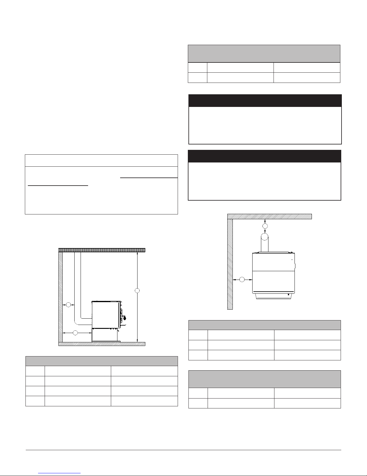
3.1 CLEARANCES TO COMBUSTIBLES
MATERIALS, WALLS AND CEILING
I
D
A
MINIMUM CLEARANCES
CANADA USA
A*
D
I**
3" (76 mm) 3" (76 mm)
Note 1 Note 1
48" (1 220 mm) 48" (1 220 mm)
WARNING
NO PART OF THE STOVE MAY BE LOCATED
CLOSER TO COMBUSTIBLES THAN THE
MINIMUM CLEARANCES SPECIFIED ON THE
CERTIFICATION LABEL.
D
B
MINIMUM CLEARANCES
CANADA USA
B
D
B
6" (152 mm) 6" (152 mm)
Note 1 Note 1
RECOMMENDED CLEARANCES FOR
MAINTENANCE
CANADA USA
24" (610 mm) 24" (610 mm)
*From the rear panel
**Measured from the platform on which the product is installed.
Note 1 : Refer to the exhaust venting system manufacturer’s
instructions for clearances to combustible materials.
Page 7INSTALLATION MANUAL ECO-55/ECO-55ST
Page 8
D
D
C
C
MINIMUM CLEARANCES
CANADA USA
C
D
3" (76 mm) 3" (76 mm)
Note 1 Note 1
RECOMMENDED CLEARANCES FOR
MAINTENANCE
CANADA USA
C
D
Note 1 : Refer to the exhaust venting system manufacturer’s
instructions for clearances to combustible materials.
12" (305 mm) 12" (305 mm)
Note 1 Note 1
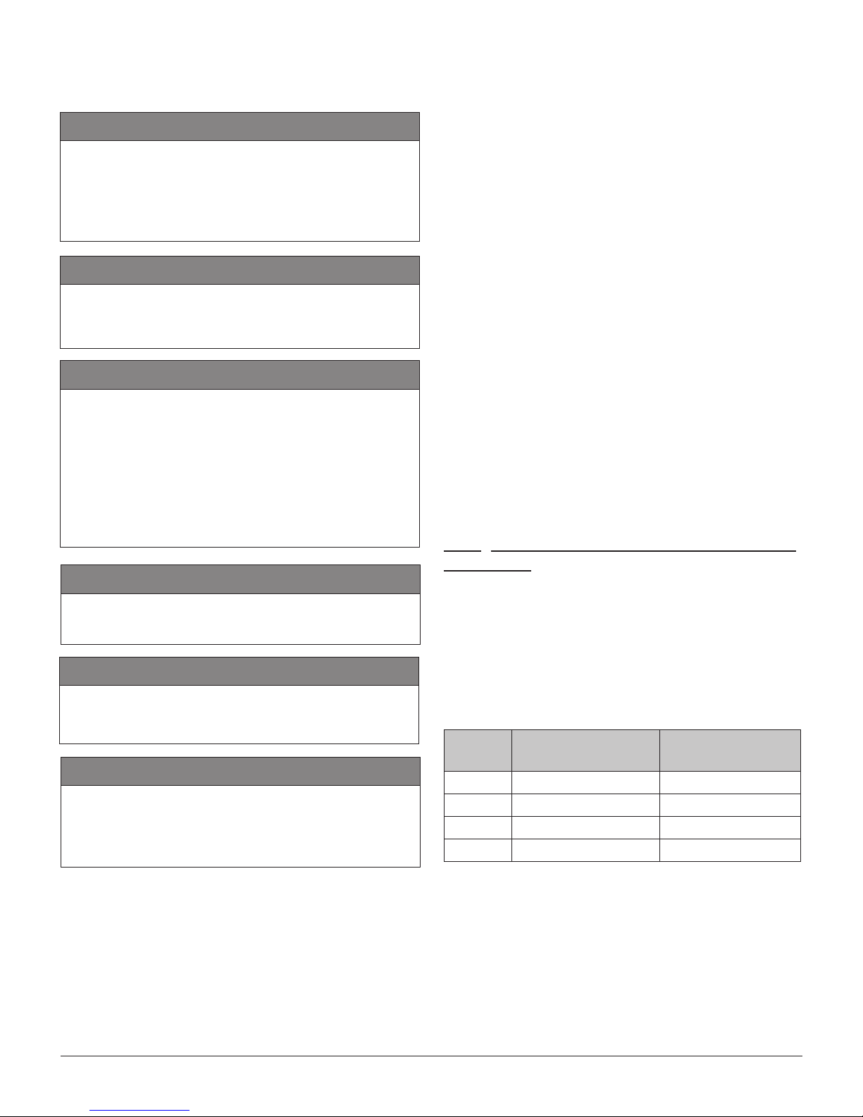
FLOOR PROTECTION
CANADA** USA
E
6" (152 mm)
From door opening
F
6" (152 mm)
From door opening
6" (152 mm)
From door opening
6" (152 mm)
From door opening
CAUTION
THE STOVE MUST BE PLACED ON
A CONTINUOUS (GROUTED JOINTS)
NONCOMBUSTIBLE MATERIAL SUCH AS
CERAMIC TILE*, CEMENT BOARD, BRICK,
MILLBOARD OR EQUIVALENT, OR ANY OTHER
APPROVED OR LISTED MATERIAL SUITED
FOR FLOOR PROTECTION.
*Any type of tile will require a continuous non combustible sheet
beneath to prevent the possibility of embers falling through to the
combustible oor if cracks or separation should occur in the nished surface, this would include oor protection for built-in raised
hearths. Check local codes for approved alternatives.
**You may reduce the oor protection requirements to the values
shown in the previous table ONLY if the following actions are
respected: Allow for the appliance to shut-down and re to
be extinguished. Once completely cool and all blowers have
stopped you may proceed with opening the rebox or ash door.
Otherwise, see CSA B365.
3.2 FLOOR PROTECTION
Page 8 INSTALLATION MANUAL ECO-55/ECO-55ST
Page 9
4. VENTING SYSTEM
4.2 RECOMMANDATIONS
CAUTION
CONNECT THIS STOVE ONLY TO A LISTED
PELLET EXHAUST VENTING SYSTEM FOR USE
WITH SOLID FUEL OR TO A LINED CHIMNEY
CONFORMING TO NATIONAL AND LOCAL
BUILDING CODES.
CAUTION
DO NOT CONNECT THIS STOVE TO ANY
OTHER EXISTING VENTING SYSTEM SERVING
ANOTHER APPLIANCE.
CAUTION
THE VENTING SYSTEM MUST BE COMPLETELY
AIRTIGHT AND PROPERLY INSTALLED.
ALL VENT CONNECTOR JOINTS MUST BE
SEALED AND FASTENED IN ACCORDANCE
WITH THE PELLET VENT MANUFACTURER’S
INSTRUCTIONS TO ENSURE CONSISTENT
PERFORMANCE AND AVOID SMOKE AND ASH
SPILLAGE..
CAUTION
In Canada, we recommend that you use a listed pellet vent that meets the CAN/ULC S609 or ULC/ORD
C441 Standard. A pellet vent listed to ULC S629M is
also suitable for installation with this stove.
For the United States, we recommend that you use a
listed pellet vent that meets the UL 641 Standard. A
pellet vent listed to UL 103 is also suitable for installation with this stove.
This stove can be vented in an existing factory-built
or masonry chimney with the addition of a stainless
steel liner, provided the chimney is more than 4" in
diameter. The liner should be listed and should meet
the ULC S635 CAN/ULC S640 standard in Canada
and the UL 1777 standard in the USA. Refer to the
instructions provided by the vent manufacturer,
especially when passing through a wall, ceiling or
roof.
4.3 EQUIVALENT VENT LENGTH (EVL)
4.3.1 RECOMMENDED EXHAUST VENTING
DIAMETER
DO NOT INSTALL A FLUE DAMPER IN THE
EXHAUST VENTING SYSTEM OF THIS UNIT.
CAUTION
DO NOT CONNECT TO OR USE IN
CONJUNCTION WITH ANY AIR DISTRIBUTION
DUCTWORK.
CAUTION
THE VENTING SYSTEM SHOULD BE CHECKED,
AT LEAST TWICE A YEAR FOR ANY BUILDUP
OF SOOT OR CREOSOTE.
4.1 GENERAL
Even though the chimney draft is mechanical, a suitable venting system will ensure a natural draft which
will prevent smoke spillage in your home if a power
outage occurs. Moreover, a suitable venting system
conguration will help getting the best efciency out
of your stove when installed in accordance with the
required EVL.
The recommended venting system inner pipe diameter is 3". Use a 4" pipe if you have more than 15 feet
of Equivalent Vent Length (EVL).
To calculate the Equivalent Vent Length of your installation, use the following conversions:
Qty Type of pipe
1 90° elbow or ‘‘Tee’’ 5 feet
1 45° elbow 3 feet
1 foot horizontal pipe run 1 foot
1 foot vertical pipe run 1/2 foot
Equivalent vent
length (EVL)
Page 9INSTALLATION MANUAL ECO-55/ECO-55ST
Page 10
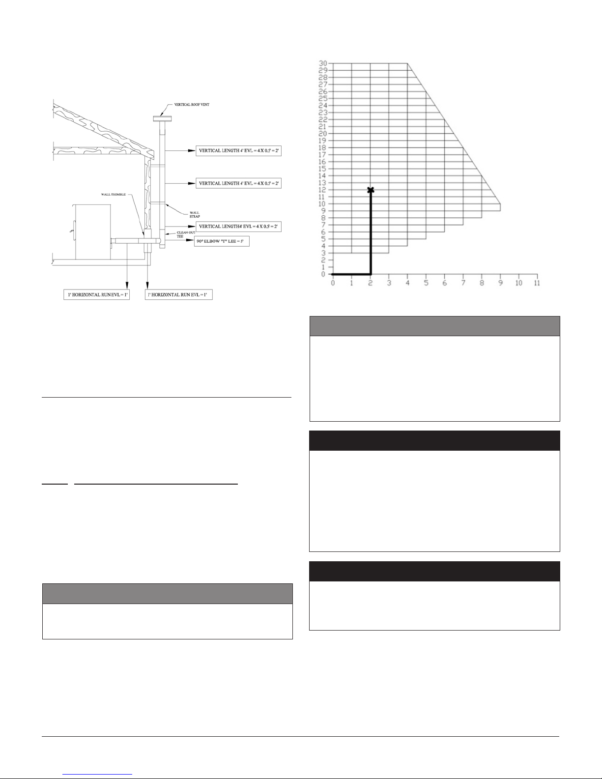
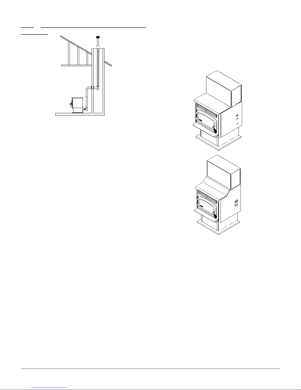
Here is an example to help you calculate Equivalent
Vent Length. On the following gure the EVL can be
calculated like this:
2 feet of horizontal run (2 X 1' EVL) = 2' of EVL
90° elbow or "Tee" (1 X 5' EVL) =5' of EVL
12 feet of vertical run
(12' X 0.5' EVL)
Termination cap = 0' of EVL
Total EVL = 13' of EVL
Since the total EVL is less than 15 feet, the recommended exhaust venting diameter is 3".
= 6’ of EVL
4.3.2 INSTALLATION COMPLIANCE
To determine if your installation is compliant, the
exhaust venting system must end within the grid on
the venting system chart. The previous installation
has 2 feet of horizontal run and 12 feet of vertical
run. It is thus standard since the venting system ends
in the gridded area.
CAUTION
• Horizontal runs shall not exceed 9 feet.
• Never exceed 30 feet of evl.
CAUTION
TO REDUCE THE RISK OF SMOKE SPILLAGE
THERE SHOULD ALWAYS BE AT LEAST ONE
FOOT OF VERTICAL RISE FOR EACH FOOT OF
HORIZONTAL RUN. IN ALL CASES, AT LEAST 3
FEET OF VERTICAL RISE IS NEEDED.
WARNING
TERMINATION OF A SIDE WALL VENT SHOULD
BE LOCATED TO AVOID PERSONAL BURN
INJURY, FIRE HAZARD AND INTERFERENCE
WITH OR DAMAGE TO ADJACENT
PROPERTIES. EXHAUST GASES CAN REACH
TEMPERATURES OF 500°F (260°C) AND CAUSE
SERIOUS BURNS.
WARNING
TERMINATION COLLAR (SPARK ARRESTER)
IS MANDATORY AND MUST BE CLEAR OF ANY
DEBRIS AT ALL TIME.
Page 10 INSTALLATION MANUAL ECO-55/ECO-55ST
Page 11
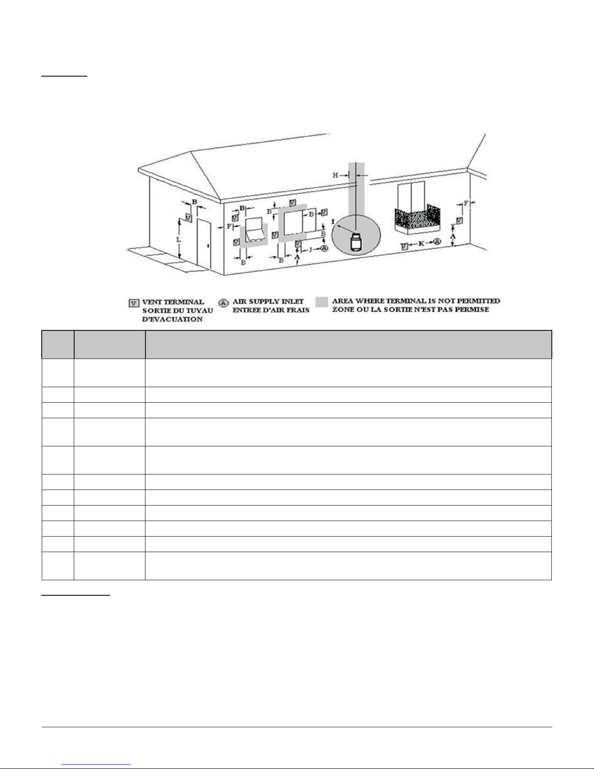
4.4 TERMINATION LOCATION
CANADA
Refer to NFPA 211 (USA) or CSA B365 (Canada) for rules for the distance of exit terminal from windows and
openings. The exit terminal of a mechanical draft system, other than a direct vent appliance shall be located
in accordance with the following.
Min.
Clearances
A 12" (30 cm) Clearances above grade level or any adjacent surface that might support snow, ice,
B 39" (100 cm) Clearance to window or door that may be opened.
F 39" (100 cm) Clearance to corner or adjacent wall or any combustible materials.
H 39" (100 cm) Not to be installed above a meter/regulator assembly within 39" (100 cm) horizontally
I 72" (183 cm) Clearance to gas service regulator vent outlet or within 39’’ (100 cm) of an oil tank vent
J 39" (100 cm) Clearance to the combustion air inlet to any other appliance.
K 72" (183 cm) Clearance to a mechanical air supply inlet.
L 84" (213 cm) Clearance above paved side-walk or a paved driveway located on public property.
39" (100 cm) Clearance to property boundary.
United-States
Description
or debris.
from the vertical center-line of the regulator and for 15’ vertically.
or an oil tank ll inlet.
A vent shall not terminate underneath a veranda, porch, or deck.
A vent shall not terminate directly above a sidewalk or a paved driveway which is lo-
cated between two single family dwelling and serves both dwellings.
• Not Less than 36" (91 cm) above any forced air inlet located within 120" (305 cm);
• Not Less than 48" (122 cm) below and horizontally from, or 12" (30 cm) above, any door, window or gravity
air inlet into any building;
• Not Less than 24" (61 cm) from an adjacent building and not less than 84" (213 cm) above grade when
located adjacent to a public walkway;
• Cannot be located less than 12" (30 cm) above grade;
• Cannot be located above a gas meter/regulator within 36" (91cm) horizontally of the vertical center line of
the regulator;
• Not within 6 feet (183 cm) of a gas service regulator vent outlet;
• Other restrictions may apply. See NFPA 211 for further information.
Page 11INSTALLATION MANUAL ECO-55/ECO-55ST
Page 12
4.5 DIRECT VENT SYSTEM
In Canada: The permitted termination locations for a
direct vent system are the same than those permitted
with a regular pellet vent system.
In the Unites States : The permitted termination
location for a direct vent system are the same than
those permitted with a regular pellet vent system
except for the following : The exit terminal shall be
located not less than 9" (23 cm) from any opening
through which vent gases could enter a building.
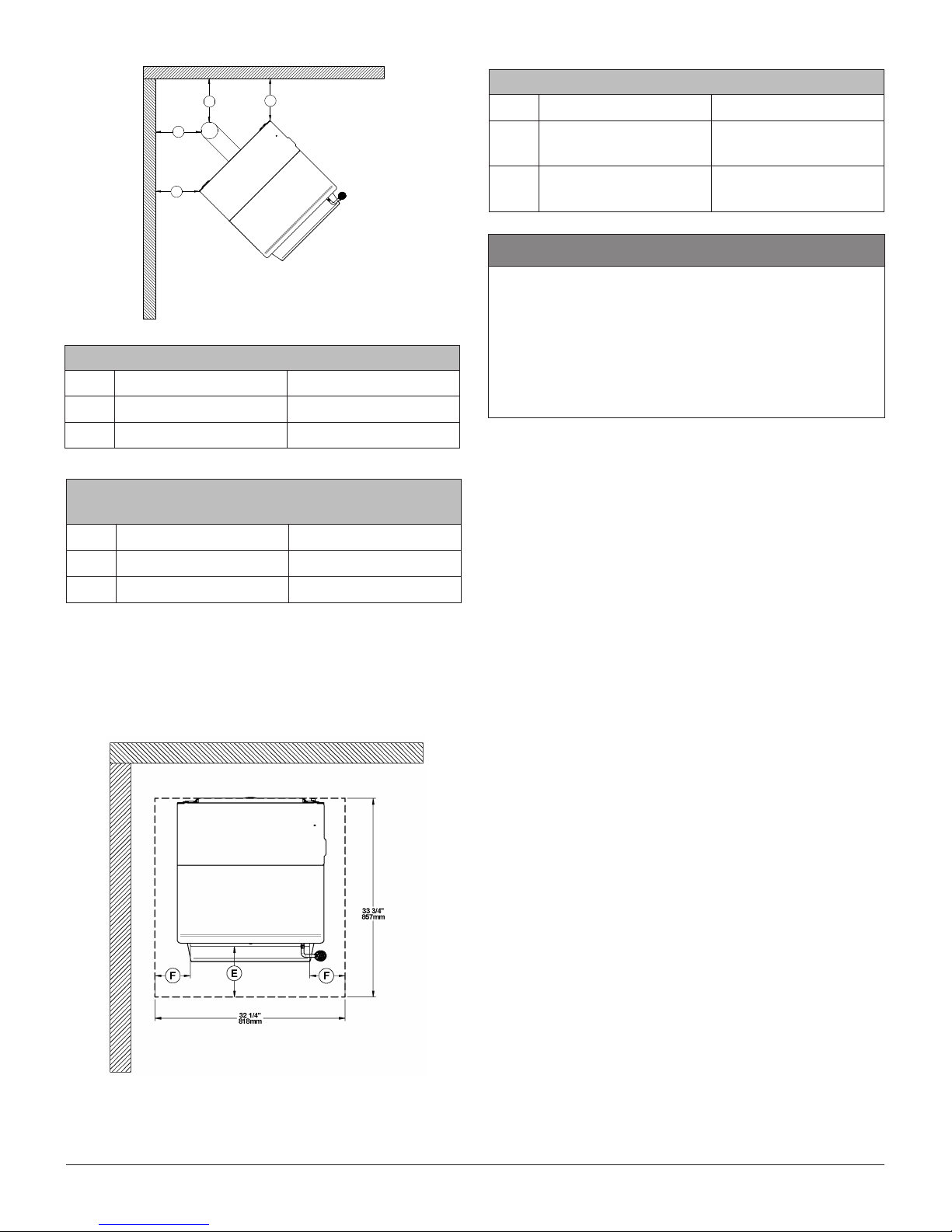
4.6 INSTALLATION CONFIGURATION
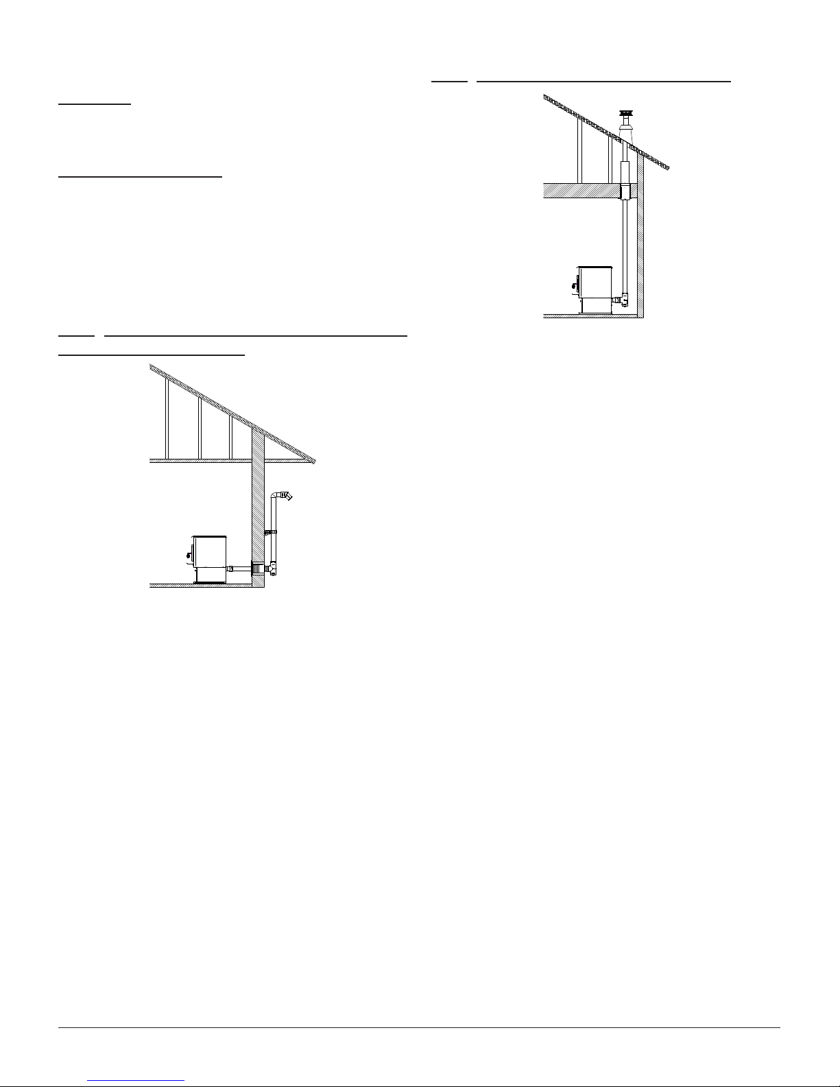
4.6.2 THROUGH ROOF INSTALLATION
4.6.1 THROUGH WALL INSTALLATION (MAIN
FLOOR OR BASEMENT)
1. Position appliance following clearances vent
manufacturer’s instructions.
2. Install a stove adapter or a stove adapter tee onto
the appliance ue collar.
3. Locate the position of the exhaust pipe in the wall
and cut a hole of the appropriate size for vent in
the wall.
4. Install wall thimble as per vent manufacturer’s
instructions.
5. Ensure you install enough horizontal pipe length
to exceed the exterior wall of 6 inches. Install a
tee section to the pipe passing through the wall.
6. Run the vent vertically up the wall for at least
36". Refer to the vent manufacturer’s instructions
for clearances to combustible materials and
installation of wall bands.
7. Install a 90 degrees elbow facing out from the
wall and then attach a 45 degree elbow facing
towards the ground. The termination of the vent
must include a spark arrester, fastened to the 45
degrees elbow.
8. Sealed outside wall thimbles with high
temperature waterproof silicone sealant.
1. Position appliance following clearances and
following vent manufacturer’s instructions.
2. Install a stove adapter or a stove adapter tee
onto the appliance ue collar. If necessary, use
a horizontal additional length between the ue
outlet and the tee.
3. Drop the plumb line over the center of the tee
outlet and mark location on the ceiling.
4. Cut a hole for appropriate ceiling support. Frame
rough opening.
5. Install ceiling support and the rst vent section as
per vent manufacturer’s instructions.
6. Install a restop radiation shield on any
subsequent ceiling/oor, except for the attic
where an attic insulation shield is required.
7. Run the necessary section of vent vertically so
the rain cap exceeds the highest point of the roof
at least 24" in United States and at least 36" in
Canada.
8. Install roof support.
9. Install roof ashing and rain cap as per
manufacturer’s instructions. If necessary, install
a storm collar.
Page 12 INSTALLATION MANUAL ECO-55/ECO-55ST
Page 13
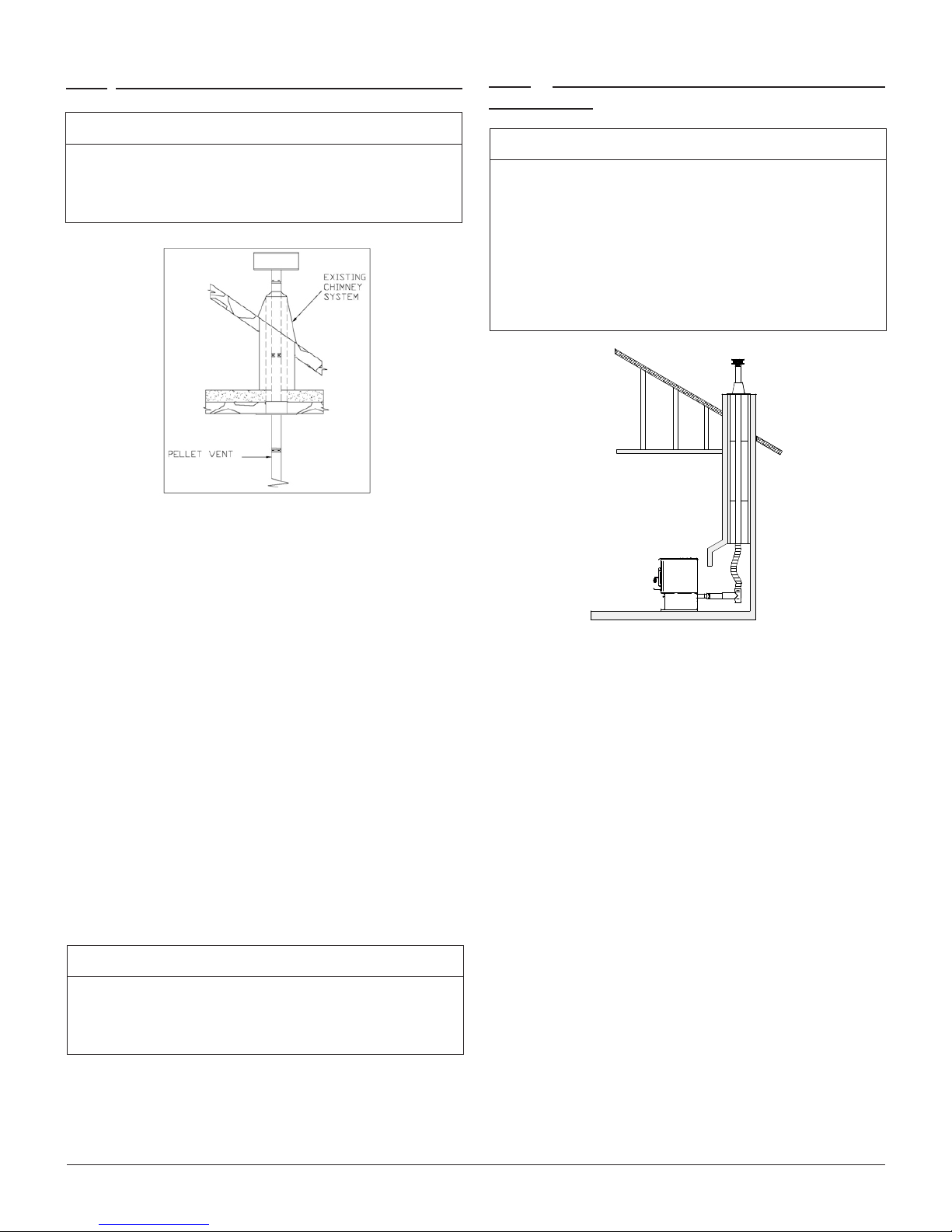
4.6.3 THROUGH A FACTORY BUILT CHIMNEY
NOTICE
Before installation, the chimney must be cleaned
and inspected by a qualied chimney sweep or
installer.
1. Position stove following clearances given and following vent manufacturer’s instructions.
4.6.4 THROUGH AN EXISTING MASONRY
FIREPLACE
NOTICE
The structural condition of the masonry chimney
must rst be inspected by a qualied chimney
sweep or installer. You will need a pipe length
equal to the chimney height from the hearth. If
outside combustion air is to be used, you will need
a pipe length superior from 12 to 18 inches (30 to
46 cm) of the chimney height to ensure a proper
stove behaviour.
2. Install a stove adapter or a stove adapter tee onto
the appliance ue collar. If necessary, use a horizontal additional length between the ue outlet
and the tee.
3. Use a proper chimney adaptor for your installation.
4. Run the number of sections of vent necessary to
go through the chimney adaptor into the chimney.
5. Connect the vent to a stainless steel 4" liner according to the vent manufacturer’s instruction.
6. Install roof ashing and rain cap as per
manufacturer’s instructions. If necessary, install
and seal a storm collar.
NOTICE
In the USA., the use of a stainless steel liner is
mandatory. In Canada, it is not mandatory but is
strongly recommended.
1. Position stove, following clearances and following vent manufacturer’s instructions.
2. Build and Install a blocking plate inside the chim-
ney to seal the replace damper. Stainless steel
plate and screws are recommended. Cut a hole
for the exhaust pipe. If needed, cut a second hole
for the air intake pipe
3. Attach a section of pipe and clean out tee to the
ue outlet, making sure the clean out tee is centered in the chimney ue area.
4. Install a vented ashing at the top of the replace
chimney. Stainless steel plate and screws are
recommended. Cut a hole for the vent pipe. If
needed, cut a second hole for the air intake pipe.
Seal all joints with high temperature waterproof
silicone sealant to prevent water leakage.
5. Seal and install vertical roof vent. If required, seal
and install a storm collar.
Page 13INSTALLATION MANUAL ECO-55/ECO-55ST
Page 14
4.6.5 THROUGH AN EXISTING MASONRY
CHIMNEY
1. Position stove following clearances following vent
manufacturer’s instructions.
2. Mark the center of the hole where the vent pipe
will go through the masonry chimney.
3. It is necessary to make a hole in the masonry
with a one-inch diameter greater than the diameter of the vent pipe used.
5. INSTALLING THE OPTIONAL
HOPPER EXTENSION
To increase the hopper capacity, it is possible to
install a hopper extension, sold separatly. Consult
your dealer or website for details.
4. Install the cleanout tee at the bottom of the vertical vent system and lower it down the chimney
until the center branch of the tee is aligned with
the hole in the masonry.
5. Connect the horizontal vent pipe to the cleanout
tee by pushing it through the hole in the masonry.
6. If desired, once the horizontal pipe is in place,
the space between the pipe and masonry may be
lled with high-temperature grout.
7. Install a vented ashing at the top of the mason-
ry chimney. Stainless steel plate and screws are
recommended. Cut a hole for the vent pipe. If
needed, cut a second hole for the air intake pipe.
Seal all joints with high temperature waterproof
silicone sealant to prevent water leakage.
8. Install and seal ashing with high temperature
waterproof silicone sealant.
9. Seal and install vertical roof vent. If required, seal
and install a storm collar.
10. If desired, install a trim collar and use an additional horizontal vent pipe length, if required, to
connect the stove to the chimney.
Page 14 INSTALLATION MANUAL ECO-55/ECO-55ST
Page 15
6. MOBILE HOME INSTALLATION
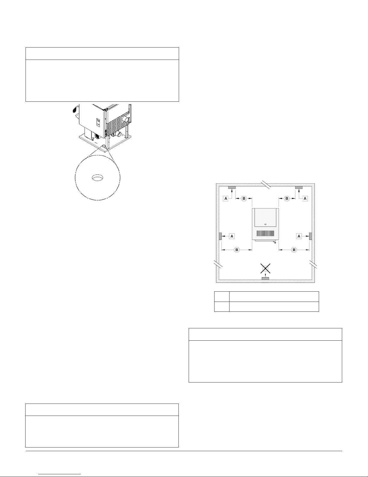
NOTICE
7.1 THERMOSTAT LOCATION
Location of the thermostat is very important to obtain
comfort and efciency from your stove.
For mobile home installation, it is mandatory to
connect the stove to an outside combustion air
source. Insulated pipe should never exceed 10
feet.
When installed in a mobile home, the stove must be
anchored to the oor with two screws. Use the two
anchoring holes located on each side of the pedes-
tal, as shown on the right gure.
Locate the thermostat 4 to 5 feet above the oor in
accordance with applicable building codes.
Install the thermostat in a location that provides
good airow characteristics and avoid areas behind
doors, near corners, air vents, direct sunlight or heat
generating devices.
If the thermostat is installed in the same room as the
stove, it should also be located at least 15 to 20 feet
from the stove. To prevent cycling, you should avoid
installing the thermostat on a poorly insulated outside
wall or directly in front of the stove.
For use in a mobile home in Canada, this pellet
stove must be connected to a vent system certied
according to the standard or ULC/ORD-C441 CAN/
ULC-S609. A vent system meeting the requirements
of ULC S629M can also be used.
For use in a manufactured home in the United States,
this pellet stove must be connected to a venting system that meets the requirements of UL 641 standard.
A vent system that meets the requirements of UL 103
standard may also be used.
7. INSTALLING A THERMOSTAT
Using a thermostat will help you maintain a constant
temperature throughout the house. A low voltage
thermostat (24 volts) is required. A xed wall mount
or hand held model can be used.
NOTICE
Thermostat manufacturer’s instructions always
override the information published in the following
section.
A Thermostat
Minimum 15'
B
NOTICE
Installing the thermostat in front of the stove or
in front of a window will tend to make the stove
cycle too often and wear components prematurely.
See operation’s manual for more details on how to
operate the stove with the proper pilot mode.
Page 15INSTALLATION MANUAL ECO-55/ECO-55ST
Page 16

7.2 WIRED THERMOSTAT
7.3 WIRELESS THERMOSTAT
Before installing the thermostat, unplug the power
cord from the power outlet.
First, connect the two thermostat wires to the terminal
block located at the rear on the right hand side of the
stove when facing it. Loosen the two middle screws
and insert the wires in the terminals. Tighten the two
screws. Open the thermostat and connect the wires
as per the manufacturer’s instructions.
If you are using a wireless thermostat or a hand
held thermostatic remote control, connect the two
thermostat wires to the terminal block located at the
rear on the right hand side of the stove while facing it.
If the receiver wires are equipped with quick-connect
terminals you can connect them directly to the stove’s
wiring harness.
To do so, open the right hand side decorative panels
and disconnect wires (B) and (C) attached to the rear
of the terminal block (A) and connect them to the receiver.
Open the thermostat and connect the wires as per
the manufacturer’s instructions.
Connect one wire on “RH” and the other wire on “W”.
Red wire jumper can remain installed. For further information refer to the manufacturer’s instructions.
8. COMBUSTION AIR SUPPLY
NOTICE
For mobile home installation, it is mandatory to
connect the stove to an outside combustion air
source. Insulated pipe should never exceed 10
feet.
It is recommended to install an outside air inlet in or
near the room where the stove is installed. When
doing so, it is preferable to choose a wall which is
not exposed to dominant winds, depending on the
conditions surrounding your house.
Page 16 INSTALLATION MANUAL ECO-55/ECO-55ST
Page 17
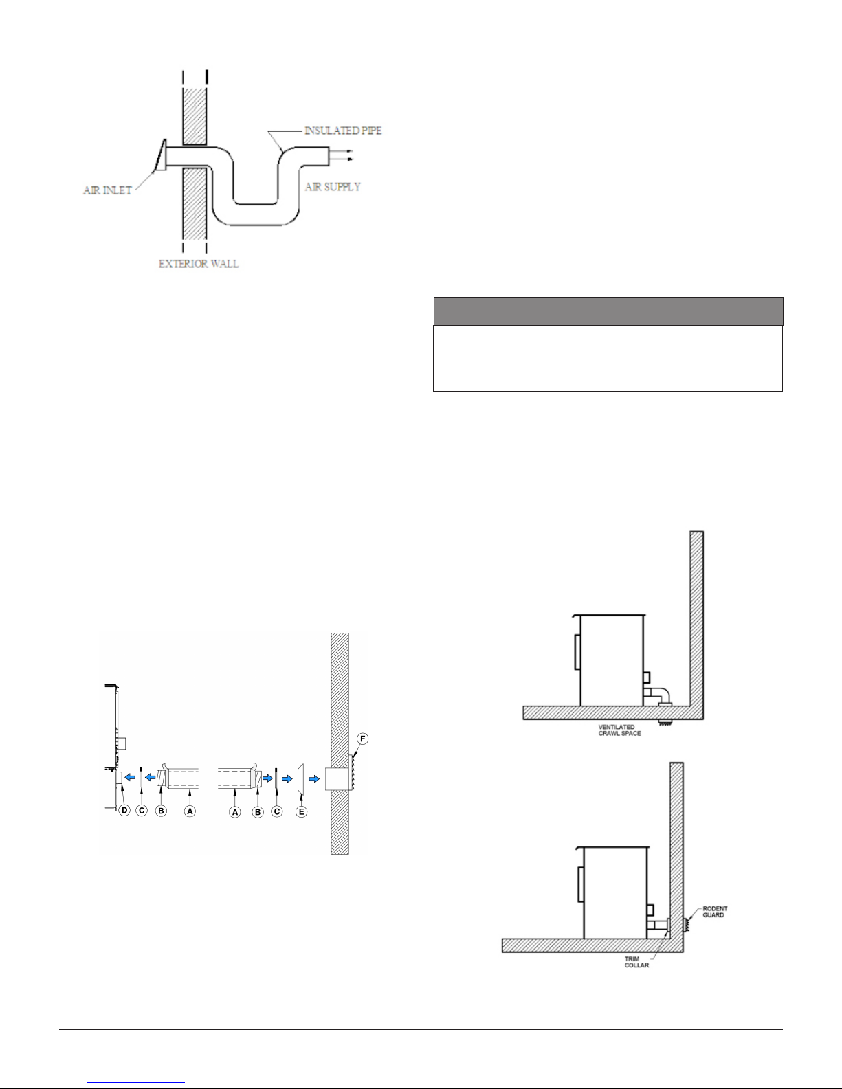
A rodent guard (minimum 1/4” wire mesh) must be
used at the termination. All connections must be
secured and airtight by either using the appropriately
sized hose clamp and/or UL-181-AP foil tape.
Make sure that the fresh air intake back draft shutter
functions freely. The fresh air intake back draft shutter
is located in the back of the stove.
8.1 SOURCES OF OUTSIDE COMBUSTION
AIR
An insulated 3” inside diameter metallic pipe, either
exible or rigid, must be attached to the fresh air intake (D).
To complete the installation, make a hole of 1/4" to
1/2" (6 mm à 13 mm) bigger than the insulate pipe
diameter in the outside wall of the house at the
chosen location. From outside, place the outside air
inlet cap (E) in the hole (open side down) and fasten
the register to the wall, with screw.
Place the insulated pipe (A) over the register tube
and over the replace outside air connector (D).
At each end, carefully pull back the insulation and
plastic cover, exposing the exible pipe. Attach the
exible pipe using pipe clamps(C).
CAUTION
IT IS FORBIDDEN TO DRAW COMBUSTION AIR
FROM A BASEMENT, AN ATTIC, A GARAGE OR
ANY CONFINED SPACE
• You can draw air from a ventilated crawl space
underneath the oor.
• You can draw air directly from an outside wall,
behind the stove.
For a better seal, you may also use aluminum tape.
Wrap the tape around the joint between the exible
pipe and the air inlets. Carefully push the insulation
and plastic cover back over the pipe. Fix the plastic
in place using aluminum tape.
Page 17INSTALLATION MANUAL ECO-55/ECO-55ST
Page 18

9. APPLIANCE SET-UP
9.1 GENERAL
Install the bafe
Make sure the fresh air intake back draft shutter
works freely.
Test the door seal by closing and latching the door
on a strip of paper. Test all around the door. The
paper should not slip out easily. If it does, see the
maintenance section in the operation manual.
Remove all tools or accessories that have been inserted in the stove for transportation purposes.
Page 18 INSTALLATION MANUAL ECO-55/ECO-55ST
Page 19

CONVECTION BLOWER
I/O BOARD
GEAR MOTOR
POT
EXHAUST
BLOWER
COMBUSTION
BLOWER
IGNITER
HOPPER SWITCH
PRESSUR
SWITCH
WHITE / BLACK STRIPE
WHITE / BLUE
STRIPES
L-250
AUTO
THERMISTOR
THERMOSTAT
(OPTION)
F-160
PURPLE
BLUE
BROWN
GREY
ORANGE
YELLOW
RED
BLACK
DETAIL C
WHITE
COMBUSTION
CONVECTION
EVACUATION
AUGER
IGNITER
DETAIL D
CONTROL
CIRCUIT
MAIN FUSE
C
D
10. WIRING DIAGRAM
Page 19INSTALLATION MANUAL ECO-55/ECO-55ST
Page 20

11. EXPLODED VIEWS AND PARTS LIST DP00070 AND DP00071
Page 20 INSTALLATION MANUAL ECO-55/ECO-55ST
Page 21

Page 21INSTALLATION MANUAL ECO-55/ECO-55ST
Page 22

Page 22 INSTALLATION MANUAL ECO-55/ECO-55ST
Page 23

51
SECTION E
52
53
54
56
57
SECTION F
59
58
60
35
75
76
32
62
61
63
32
71
72
73
64
74
65
66
67
68
68
101
69
63
102
70
Page 23INSTALLATION MANUAL ECO-55/ECO-55ST
Page 24

Page 24 INSTALLATION MANUAL ECO-55/ECO-55ST
Page 25

SECTION I
49
94
58
97
98
Page 25INSTALLATION MANUAL ECO-55/ECO-55ST
Page 26

IMPORTANT: THIS IS DATED INFORMATION. When requesting service or replacement parts for your
stove, please provide the model number and the serial number. We reserve the right to change parts
due to technology upgrade or availability. Contact an authorized dealer to obtain any of these parts.
Never use substitute materials. Use of non-approved parts can result in poor performance and safety
hazards and will void your warranty.
# Part Description Qty
1 PL69808 RIGHT SIDE DECORATIVE PANEL 1
2 PL69809 LEFT SIDE DECORATIVE PANEL 1
3 PL69806 LOWER RIGHT SIDE DECORATIVE PANEL 1
4 PL69807 LOWER LEFT SIDE DECORATIVE PANEL 1
5 PL69801 HOPPER LID 1
6 PL69794 BACK PANEL 1
7 PL69795 LOWER BACK PANEL 1
8 SE69810 ASH DRAWER 1
9 99999 BUILD TO ORDER 1
10 PL69833 LEFT SIDE DECORATIVE PANEL 1
11 PL69854 BACK PANEL 1
12 PL69832 RIGHT SIDE DECORATIVE PANEL 1
13 30105P COIL HANDLE 1/2" BLACK 1
14 SE24085 DOOR FRAME WITH HANDLE AND GASKET WITHOUT GLASS 1
15 AC06200 SILICONE AND 1/4'' X 1/2'' X 11' BLACK GASKET KIT 1
16 AC09176 DOOR HANDLE AND LATCH KIT 1
17 AC09185 DOOR LATCH KIT 1
18 PL52683 REMOVABLE HANDLE 1
19 30101 SPRING TENSION PIN 5/32" DIA X 1 1/2" L 1
20 SE52708 ARCHED REPLACEMENT GLASS WITH GASKET 7 51/64" X 16 3/4" X 8
1
23/32"
21 AC06400 3/4" (FLAT) X 6' BLACK SELF-ADHESIVE GLASS GASKET 1
22 PL52717 HINGE SIDE GLASS RETAINER 1
23 PL08537-04 TOP GLASS RETAINER 1
24 PL52719 HANDLE SIDE GLASS RETAINER 1
25 PL52718 AIR DEFLECTOR TRIM 1
26 30124 SCREW #8 - 32 X 5/16'' TRUSS QUADREX ZINC 12
27 30170 HINGE PIN 5/16" DIA X 1 1/2" L (0.309 TO 0.312) 2
28 30055 HINGE PIN RETAINING RING 5/16" ID X 0.512" OD 2
29 SE16059 ASH PLUG 1
30 SE69759 BURN POT 1
31 44192 IGNITOR TUBE 1
32 30029 THREAD CUTTING SCREW 10-24 TYPE "F" X 3/8" HEX WASHER 16
33 SE44132 IGNITER ASSEMBLY 120V 300W 1
34 PL69777 FIRE BAFFLE 1
35 30417 BLACK HEX NUT #8-32 3
Page 26 INSTALLATION MANUAL ECO-55/ECO-55ST
Page 27

# Part Description Qty
36 30370 RUBBER BUMPER WITH THREADS (SMALL) 3
37 44098 HOPPER LID SAFETY SWITCH 1
38 30013 HINGE 2'' X 1 1/2'' 2
39 SE69785 EXHAUST PIPE ASSEMBLY 1
40 21392 EXHAUST ADAPTER GASKET 1
41 30093 BOLT 1/4-20 X 3/4" HEX GRADE 5 2
42 44144 EXHAUST FAN 1
43 30094 HEX SCREW WASHER HEAD 1/4-20 X 3/4" F ZINC TYPE 1
44 30220 FLANGED LOCKNUT 1/4-20 2
45 SE44095 THERMISTOR ASSEMBLY 1
46 21393 EXHAUST BLOWER GASKET 1
47 PL69764 SUPPORT EXHAUST TRAP 1
48 SE69803 EXHAUST CLEANING PANEL ASSEMBLY 1
49 AC06815 BLACK GASKET AND SILICONE KIT 3/16'' X 5' 1
50 30484 WING NUT 1/4-20 2
51 24017 CAST IRON AUGER 1
52 44059 THERMODISC 36T11 L250-25 AUTOMATIC 1
53 30138 METAL SCREW #6 3/8'' QUADREX ''A'' TYPE BLACK 2
54 30092 BOLT 5/16''-18 X 3/4" HEX GRADE 5 2
55 30528 BRASS BUSHING FOR PELLET STOVE AUGER 1
56 21110 AUGER PLATE GASKET 1
57 PL69773 AUGER BUSHING SUPPORT PLATE 1
58 30026 THREAD CUTTING SCREW 10-24 F 5/8" HEX WASHER HEAD 10
59 30369 RUBBER BUMPER WITH THREADS (LARGE) 1
60 44106 GEAR MOTOR FOR PELLET STOVE AUGER 1.5 RPM 1
61 SE69791 CONTROL BOARD BOX ASSEMBLY 1
62 44148 MEMBRANE SWITCH CONTROL BOARD 1
63 PL69855 CONTROL BOARD 55 SERIE 1
64 60382 WIRING HARNESS 1
65 44058 THERMODISC 36T12 F160 1
66 30080 METAL SCREW #6 X 1/4 TYPE B PAN PHILLIPS 2
67 44149 FUSE 8A / 250V (5 X 20) F3-MAIN OR F8 IGNITER 1
68 44152 FUSE 0.5A / 250V (5 X 20) F2-INTERFACE 2
69 44200 FUSE GLASS 2A 250VAC 5X20MM SLOW BLOW 1
70 44201 FUSE GLASS 4A 250VAC 5X20MM SLOW BLOW 1
71 60036 THERMOSTAT TERMINAL 1
72 60196 POWER CORD RECEPTACLE 1
73 30155 METAL SCREW #8 X 5/8'' PHILLIPS SELFTAPPING TEK ZINC 4
74 60331 POWER CORD 6' 1
75 49004 PRESSURE SWITCH HOSE 1
76 44029 PRESSURE SWITCH 1
77 SE69849 AIR CONTROL DAMPER ASSEMBLY 1
Page 27INSTALLATION MANUAL ECO-55/ECO-55ST
Page 28

# Part Description Qty
78 PL69784 AIR INTAKE PLATE 1
79 30021 SELF TAPPING SCREW 8-32 "F" TYPE X 7/16" FLAT HEAD PHILLIPS
2
BLACK
80 30439 SPRING CLAMP ZINC PLATED BRIGHT CHROMATE DIP 1
81 PL64359 COMBUSTION FAN GASKET FRAME 1
82 21400 COMBUSTION FAN GASKET 2
83 SE44147 AXIAL BLOWER ASSEMBLY 115V 9W 92 X 92 X 38 1
84 PL69799 AIR CONTROL BRACKET 1
85 30777 PLASTIC BACKDRAFT DAMPER ASSEMBLY 1
86 30502 SELF TAPING SCREW #8 - 32 X 1/2" TYPE F x 3/4 HEX FLAT HEAD 4
87 30556 AIR CONTROL FINISHING TIP 1
88 49400 2 1/2" TO 3 1/2" STEEL COLLAR 2
89 21381 2 FOLD ALUMINUM LINER 3" X 6'' COMPRESSED 1
90 60383 IGNITER JUNCTION WIRE 1
91 30100 BLACK HEX NUT 1/4 - 20 4
92 30185 17/64" "AA" TYPE WASHER 4
93 44122 DOUBLE CAGE BLOWER 176 CFM (CLASS H) 1
94 30485 WING NUT 1/4-20 X 1/2'' ZINC PLATTED 3
95 PL69805 CONVECTION FAN SUPPORT 1
96 30446 CARRIAGE BOLT 1/4 - 20 x 1" ZINC 4
97 PL69802 CLEANING ACCESS PANEL SUPPORT 1
98 SE69804 CLEANING ACCESS PANEL WITH GASKET 1
99 45876 USER MANUAL 1
100 AC05959 METALLIC BLACK STOVE PAINT - 342 g (12oz) AEROSOL 1
101 44150 FUSE 3A / 250V (5 X 20) F4-AUGER & DC IEC CONNECTOR 1
102 44199 FUSE GLASS 1.25A 250VAC 5X20MM SLOW BLOW 1
Page 28 INSTALLATION MANUAL ECO-55/ECO-55ST
Page 29

MANUEL D’INSTALLATION
ECO-55 et ECO-55 ST
(modèle DP00070 et DP00071)
Essai de sécurité fait conformément aux normes
ULC S627, UL 1482 et ASTM E1509 par un
laboratoire accrédité
L’INSTALLATION PAR UN
PROFESSIONNEL EST FORTEMENT
RECOMMANDÉE
Fabricant de poêles international inc.
250, rue de Copenhague,
St-Augustin-de-Desmaures (Québec) Canada
G3A 2H3
CONTACTEZ VOTRE SERVICE MUNICIPAL DU BÂTIMENT OU DES INCENDIES POUR CONNAÎTRE
LES RESTRICTIONS ET LES EXIGENCES D’INSPECTION ET D’INSTALLATION DANS VOTRE RÉGION.
LISEZ CE MANUEL AU COMPLET AVANT D’INSTALLER VOTRE NOUVEAU POÊLE. IL EST IMPORTANT
DE RESPECTER INTÉGRALEMENT LES DIRECTIVES D’INSTALLATION. SI LE POÊLE N’EST PAS
INSTALLÉ CORRECTEMENT, IL PEUT EN RÉSULTER UN INCENDIE, DES BLESSURES CORPORELLES
OU MÊME LE DÉCÈS.
LIRE LE PRÉSENT MANUEL ET LE CONSERVER POUR CONSULTATION
Ce manuel peut être téléchargé gratuitement à partir du site web du manufacturier. Il s’agit d’un document dont les
droits d’auteur sont protégés. La revente de ce manuel est formellement interdite. Le manufacturier se réserve le
droit de modier ce manuel de temps à autre et ne peut être tenu responsable de tous problèmes, blessures ou
dommages subis suite à l’utilisation d’information contenue dans tout manuel obtenu de sources non autorisées.
Imprimé au Canada
Service aux consommateurs : 418-908-8002
Courriel : tech@sbi-international.com
www.drolet.ca
45876IF_2017-02-07
Page 30

1. CONSIGNES DE SÉCURITÉ
ATTENTION
Nous recommandons fortement que nos produits
de chauffage soient installés par des professionnels
certiés aux États-Unis par le NFI (National Fireplace
Institute®) ou au Canada par WETT (Wood Energy
Technology Transfer) ou au Québec par l’APC
(Association des Professionnels du Chauffage).
Lorsque ce poêle n’est pas installé correctement,
les matériaux combustibles à proximité peuvent
surchauffer. Pour réduire les risques d’incendie,
suivez les instructions d’installation de ce manuel
intégralement. Contactez votre service municipal
du bâtiment ou des incendies pour connaître
les restrictions et les exigences d’inspection et
d’installation dans votre région.
Lisez ce manuel au complet avant d’installer et
d’utiliser votre nouveau poêle. Il se peut que vous
deviez vous procurer un permis pour l’installation du
poêle et du système d’évent sur lequel il est branché.
Communiquez avec votre service municipal du
bâtiment ou des incendies avant l’installation. Nous
vous recommandons également de demander à votre
compagnie d’assurance habitation si cette installation
aura une incidence sur votre police d’assurance.
ATTENTION
IL EST FORTEMENT DÉCONSEILLÉ
D’INSTALLER CE POÊLE DANS UNE CHAMBRE
À COUCHER.
CE POÊLE EST APPROUVÉ MAISON MOBILE
ET REQUIERT L’INSTALLATION D’UN
ENSEMBLE D’ENTRÉE D’AIR FRAIS, VENDU
SÉPARÉMENT. LE POÊLE DOIT ÊTRE FIXÉ À
LA STRUCTURE DE LA MAISON MOBILE ET
L’INTÉGRITÉ STRUCTURALE DU PLANCHER,
DES MURS, DU PLAFOND ET DU TOIT DE LA
MAISON MOBILE DOIT ÊTRE MAINTENUE. IL
EST INTERDIT D’INSTALLER CE POÊLE DANS
UNE CHAMBRE À COUCHER D’UNE MAISON
MOBILE.
MISE EN GARDE
CE POÊLE DOIT ÊTRE BRANCHÉ DANS UNE
PRISE STANDARD DE 120V / 60HZ, AVEC MISE
À LA TERRE. NE PAS UTILISER D’ADAPTATEUR
ÉLECTRIQUE. NE PAS ENDOMMAGER OU
ENLEVER LA MISE À LA TERRE. NE FAITES
JAMAIS PASSER LE CORDON D’ALIMENTATION
ÉLECTRIQUE EN AVANT, AU-DESSUS OU EN
DESSOUS DU POÊLE.
REMARQUE
L’utilisation de composants provenant d’autres
appareils ou la modication des composants actuels
du poêle sont interdites et annuleront la garantie.
Toute modication de l’appareil qui n’a pas été
approuvée par écrit par l’autorité d’homologation
ou le manufacturier est interdite et viole les normes
CSA B365 (Canada) et NFPA 211 (É.-U.).
ATTENTION
L’INSTALLATION INADÉQUATE DE VOTRE
APPAREIL POURRAIT CAUSER UN INCENDIE.
POUR RÉDUIRE LES RISQUES, SUIVEZ LES
INSTRUCTIONS D’INSTALLATION.
ATTENTION
BRÛLER DES COMBUSTIBLES SOLIDES
GÉNÈRE DU MONOXYDE DE CARBONE EN
FAIBLE CONCENTRATION. CES GAZ SONT
EXPULSÉS PAR LE SYSTÈME D’ÉVACUATION.
DES CONCENTRATIONS PLUS ÉLEVÉES EN
MONOXYDE DE CARBONE SONT TOXIQUES ET
PEUVENT CAUSER LA MORT. AFIN D’ÉVITER
UN EMPOISONNEMENT, ASSUREZ-VOUS QUE
VOTRE SYSTÈME D’ÉVENT EST ÉTANCHE.
Page 2 MANUEL D’INSTALLATION ECO-55/ECO-55ST
REMARQUE
Lors du choix de l’emplacement de l’appareil,
assurez-vous que le système d’évent n’entre pas
en conit avec les solives de plancher, les chevrons
de toit, les montants, les conduites d’eau ou les ls
électriques. Il est plus facile de relocaliser l’appareil
que de modier la structure de l’habitation.
REMARQUE
Les informations inscrites sur la plaque
d’homologation de l’appareil ont toujours préséance
sur les informations contenues dans tout autre
média publié (manuels, catalogues, circulaires,
revues ou sites web).
Page 31

REMARQUE
Ce poêle a été conçu et développé pour être utilisé
comme chauffage d’appoint résidentiel. Un usage
commercial ou industriel est interdit et annulera la
garantie.
REMARQUE
SBI - Fabricant de poêles international inc.
n’assume aucune garantie implicite ou explicite liée
à la mauvaise installation de l’appareil et n’assume
aucune responsabilité pour tout dommage qui en
résulterait.
Page 3MANUEL D’INSTALLATION ECO-55/ECO-55ST
Page 32

TABLE DES MATIÈRES
1. CONSIGNES DE SÉCURITÉ ............................................................................. 2
2. INFORMATIONS GÉNÉRALES ......................................................................... 5
2.1 DIMENSIONS EXTÉRIEURES (DP00070) ............................................................................5
2.2 DIMENSIONS EXTÉRIEURES (DP00071) .............................................................................6
2.3 RÈGLEMENTS RÉGISSANT L’INSTALLATION D’UN POÊLE À GRANULES ................... 6
2.4 LOCALISATION DE LA PLAQUE D’HOMOLOGATION .......................................................6
3. DÉGAGEMENTS AUX MATÉRIAUX COMBUSTIBLES .................................... 7
3.1 DÉGAGEMENTS AUX MURS ET PLAFOND .......................................................................7
3.2 PROTECTION DE PLANCHER .............................................................................................8
4. SYSTÈME D’ÉVENT .......................................................................................... 9
4.1 GÉNÉRAL ..............................................................................................................................9
4.2 RECOMMANDATIONS ..........................................................................................................9
4.3 LONGUEUR D’ÉVENT ÉQUIVALENT (LEE) ........................................................................9
4.3.1 DIAMÈTRE DU SYSTÈME D’ÉVENT RECOMMANDÉ ......................................................9
4.3.2 CONFORMITÉ DE L’INSTALLATION .................................................................................. 10
4.4 LOCALISATION DE LA TERMINAISON ...............................................................................11
4.5 SYSTÈME D’ÉVACUATION DIRECT (ÉVACUATION ET ENTRÉE D’AIR 2 EN 1) .............12
4.6 CONFIGURATIONS D’INSTALLATION .................................................................................12
4.6.1 INSTALLATION À TRAVERS UN MUR (REZ-DE-CHAUSSÉ OU SOUS-SOL) .................. 12
4.6.2 INSTALLATION À TRAVERS LE TOIT ................................................................................12
4.6.3 INSTALLATION À TRAVERS UNE CHEMINÉE PRÉFABRIQUÉE .....................................13
4.6.4 INSTALLATION À TRAVERS UN FOYER DE MACONNERIE EXISTANT .........................13
4.6.5 INSTALLATION À TRAVERS UNE CHEMINÉE DE MACONNERIE. .................................14
5. INSTALLATION DE L’EXTENTION DE TRÉMIE OPTIONNELLE. ................... 14
6. INSTALLATION DANS UNE MAISON MOBILE ............................................... 15
7. INSTALLATION D’UN THERMOSTAT .............................................................. 15
7.1 LOCALISATION DU THERMOSTAT .....................................................................................15
7.2 THERMOSTAT FIXE ..............................................................................................................16
7.3 THERMOSTAT SANS FIL ......................................................................................................16
8. APPORT D’AIR DE COMBUSTION ..................................................................16
8.1 SOURCES D’AIR DE COMBUSTION EXTÉRIEURE ...........................................................17
9. AVANT D’OPÉRER L’APPAREIL ...................................................................... 18
9.1 GÉNÉRAL ..............................................................................................................................18
10. SCHÉMA ÉLECTRIQUE .................................................................................. 19
11. VUES EXPLOSÉES ET LISTE DE PIÈCES DP00070 ET DP00071 .............. 20
Page 4 MANUEL D’INSTALLATION ECO-55/ECO-55ST
Page 33

2. INFORMATIONS GÉNÉRALES
25 1/4"
640mm
22 7/8"
581mm
24 7/8"
632mm
29 1/2"
750mm
23 7/8"
607mm
24 7/8"
8 5/8"
218mm
17 3/8"
441mm
32 5/8"
829mm
O
3"
76mm
O
3"
76mm
11 3/8"
290mm
6 1/8"
155mm
A
B
A
B
15 3/4"
401mm
8 1/8"
205mm
23 7/8"
607mm
24 7/8"
633mm
8 5/8"
218mm
17 3/8"
441mm
32 5/8"
829mm
O
3"
76mm
O
3"
76mm
11 3/8"
290mm
6 1/8"
155mm
A
B
A
B
O
3"
76mm
O
3"
76mm
11 3/8"
290mm
6 1/8"
155mm
A
B
2.1 DIMENSIONS EXTÉRIEURES (DP00070)
Diamètre de cheminée
3 po. (75 mm)
recommandé
Diamètre de la buse de
3 po. (75 mm)
raccordement
Type de Cheminée ULC/ORD-C441
CAN/ULC S609
UL 641 (TYPE L)
Approuvé pour
Oui
installation en alcôve
Approuvé pour
Oui
installation en maison
mobile ‡
Poids à l’expédition
(sans options)
Poids de l’appareil
(sans options)
Normes d’émission de
particules
Norme américaine
(sécurité)
Norme canadienne
277 lb (DP00070)
286 lb (DP00071)
235lb (DP00070)
242lb (DP00071)
CSA B415.1-10
ASTM E2779
ASTM E1509
UL 1482
ULC S627
(sécurité)
Spécications électriques Tension et fréquence
120VAC et 60 Hz
24 7/8"
632mm
29 1/2"
750mm
Allumage : 3.02A
‡ Maison mobile (Canada) ou maison préfabriquée (É.-U.) : Le
département américain du logement et du développement urbain
décrit «maisons préfabriquées» mieux connues pour «maisons
mobiles» comme suit ; bâtiments construits sur des roues xes
et ceux transportés sur des roues/essieux temporaires installées
sur une fondation permanente. Au Canada, une maison mobile
est une habitation dont l’assemblage de chaque composante
est achevé ou achevé en grande partie avant le déplacement
de celle-ci jusqu’à un emplacement pour y être placée sur
des fondations, raccordé à des installations de service et qui
rencontre la norme CAN/CSA-Z240 MH.
A PRISE POUR
ENTRÉE D’AIR
FRAIS
B BUSE DE
RACCORDEMENT
Page 5MANUEL D’INSTALLATION ECO-55/ECO-55ST
Page 34

2.2 DIMENSIONS EXTÉRIEURES (DP00071)
23 7/8"
607mm
24 7/8"
633mm
8 5/8"
218mm
17 1/4"
439mm
36 1/8"
918mm
25 1/8"
639mm
22 7/8"
581mm
8 1/8"
205mm
15 3/4"
401mm
24 7/8"
632mm
29 1/2"
750mm
A
B
A
B
O
3"
76mm
O
3"
76mm
11 3/8"
290mm
6 1/8"
155mm
23 7/8"
607mm
24 7/8"
633mm
8 5/8"
218mm
17 1/4"
439mm
36 1/8"
918mm
A
B
A
B
O
3"
76mm
O
3"
76mm
11 3/8"
290mm
6 1/8"
155mm
A
B
O
3"
76mm
O
3"
76mm
11 3/8"
290mm
6 1/8"
155mm
24 7/8"
632mm
29 1/2"
750mm
2.3 RÈGLEMENTS RÉGISSANT L’INSTALLATION D’UN POÊLE À GRANULES
Lorsqu’il est installé et utilisé tel que décrit dans les
présentes instructions, ce poêle à granules convient
comme appareil de chauffage d’appoint pour
installation résidentielle.
Au Canada, il faut respecter le CSA B365 Installation
des appareils de chauffage à combustible solide et
du matériel connexe et le CSA C22.1 Code canadien
de l’électricité en l’absence de code local.
Aux États-Unis, il faut suivre le ANSI NFPA 211
Standard for Chimneys, Fireplaces, Vents and Solid
Fuel-Burning Appliances et le ANSI NFPA 70 National
Electrical Code en l’absence de code local.
Ce poêle à granules doit être raccordé à un système
d’évent conforme aux exigences de système d’évent
pour appareil à granules de bois dans la norme
pour cheminées préfabriquées de type résidentiel
et appareils de chauffage de bâtiment, UL 103, UL
641, ULC S629M, CAN/ULC S609 et ULC/ORD
C441 ou à une cheminée de maçonnerie approuvée
selon le code avec une gaine de cheminée en acier
inoxydable.
A PRISE POUR
Page 6 MANUEL D’INSTALLATION ECO-55/ECO-55ST
B BUSE DE
ENTRÉE D’AIR
FRAIS
RACCORDEMENT
2.4 LOCALISATION DE LA PLAQUE D’HOMOLOGATION
Puisque les informations inscrites sur la plaque
d’homologation de l’appareil ont toujours préséance
sur les informations contenues dans tout autre média
publié (manuels, catalogues, circulaires, revues ou
sites web) il est important de vous y référer an
d’avoir une installation sécuritaire et conforme. De
plus, vous y trouverez des informations importantes
concernant votre appareil (modèle, numéro de série,
etc.) Vous trouverez la plaque d’homologation à
l’intérieur du panneau de la trémie.
MISE EN GARDE
N’UTILISEZ PAS DE MATÉRIAUX DE FORTUNE
ET NE FAITES PAS DE COMPROMIS LORSQUE
VOUS INSTALLEZ LE POÊLE.
Page 35

3. DÉGAGEMENTS AUX MATÉRIAUX
COMBUSTIBLES
Les dégagements donnés dans la présente section
s’appliquent au DP00070 ainsi qu’au DP00071.
Les dégagements donnés dans la présente section
ont été établis à partir d’essais conformément aux
procédures décrites dans les normes ULC S627
(Canada) et ASTM E1509 (USA) et UL1482 (USA).
Lorsque les dégagements minimums indiqués
sont respectés, les surfaces combustibles ne
surchaufferont pas en usage normal et même en
usage anormal.
REMARQUE
Ces dégagements sont aussi valides pour une
installation dans une alcôve. Par contre, si
l’appareil est installé dans une alcôve, pour faire
votre entretien vous devrez prévoir déplacer
l’appareil pour accéder aux trappes de nettoyage
et aux composants.
3.1 DÉGAGEMENTS AUX MURS ET PLAFOND
ATTENTION
AUCUNE PARTIE DU POÊLE NE PEUT ÊTRE
PLACÉE PLUS PRÈS DES MATÉRIAUX
COMBUSTIBLES QUE LES DÉGAGEMENTS
MINIMUMS INDIQUÉS SUR LA PLAQUE
D’HOMOLOGATION.
ATTENTION
AUCUNE PARTIE DU SYSTÈME D’ÉVENT
NE PEUT ÊTRE PLACÉE PLUS PRÈS DES
MATÉRIAUX COMBUSTIBLES QUE LES
DÉGAGEMENTS MINIMUMS INDIQUÉS PAR LE
MANUFACTURIER DU SYSTÈME D’ÉVENT.
D
I
D
A
DÉGAGEMENTS MINIMAUX
CANADA É-U
A*
D
I**
* À partir de la tôle arrière
**Mesuré à partir de la plateforme sur laquelle le produit est
déposé.
3" (76 mm) 3" (76 mm)
Note 1 Note 1
48" (1 220 mm) 48" (1 220 mm)
B
DÉGAGEMENTS MINIMAUX
CANADA É-U
B
D
6" (152 mm) 6" (152 mm)
Note 1 Note 1
DÉGAGEMENTS RECOMMANDÉS POUR
L’ENTRETIEN
CANADA É-U
B
Note 1 : Se référer aux instructions du manufacturier du système
d’évent pour les dégagements aux matériaux combustibles.
24" (610 mm) 24" (610 mm)
DÉGAGEMENTS RECOMMANDÉS POUR
L’ENTRETIEN
CANADA É-U
A*
12" (305 mm) 12" (305 mm)
Page 7MANUEL D’INSTALLATION ECO-55/ECO-55ST
Page 36

CANADA
PROTECTION DE PLANCHER
D
D
C
E
CANADA** É-U
6" (152 mm)
De l’ouverture de porte
De l’ouverture de porte
6" (152 mm)
C
DÉGAGEMENTS MINIMAUX
CANADA É-U
C
D
3" (76 mm) 3" (76 mm)
Note 1 Note 1
DÉGAGEMENTS RECOMMANDÉS POUR
L’ENTRETIEN
CANADA É-U
C
D
Note 1 : Se référer aux instructions du manufacturier du système
d’évent pour les dégagements aux matériaux combustibles.
12" (305 mm) 12" (305 mm)
Note 1 Note 1
F
6" (152 mm)
De l’ouverture de porte
6" (152 mm)
De l’ouverture de porte
MISE EN GARDE
LE POÊLE DOIT ÊTRE PLACÉ SUR UNE
SURFACE INCOMBUSTIBLE CONTINUE TELLE
QUE DE LA CÉRAMIQUE*, UN PANNEAU
DE BÉTON, DE LA BRIQUE, UN PANNEAU
D’AGGLOMÉRÉ INCOMBUSTIBLE OU TOUT
AUTRE MATÉRIEL ÉQUIVALENT, APPROUVÉ
COMME PROTECTION DE PLANCHER.
*La céramique doit être placée sur un panneau incombustible
continu an d’éviter que des tisons puissent être mis en contact
avec le plancher à travers des ssures ou des manques dans le
coulis de la céramique, ceci inclut la protection de plancher pour
les âtres de foyers déjà existants. Vérier le code local pour les
alternatives approuvées.
**Vous pouvez utiliser les dimensions de la protection de plancher mentionnées dans le tableau précédent SEULEMENT si
vous acceptez d’attendre que l’unité soit complètement éteinte,
c’est-à-dire qu’il n’y ait plus de feu dans le pot de combustion et
que les ventilateurs soient éteints, avant d’ouvrir la porte de l’unité ou d’enlever le tiroir à cendres. Sinon, voir CSA B365.
3.2 PROTECTION DE PLANCHER
F
E
32 1/4"
818mm
F
33 3/4"
856mm
Page 8 MANUEL D’INSTALLATION ECO-55/ECO-55ST
Page 37

4. SYSTÈME D’ÉVENT
MISE EN GARDE
RACCORDER LE POÊLE SEULEMENT À UN
SYSTÈME D’ÉVENT HOMOLOGUÉ POUR
UTILISATION AVEC DU COMBUSTIBLE SOLIDE
OU À UNE CHEMINÉE CONFORME AUX CODES
DU BÂTIMENT NATIONAL ET LOCAL.
MISE EN GARDE
4.2 RECOMMANDATIONS
Au Canada, nous recommandons l’usage d’un sys-
tème d’évent répondant aux exigences des normes
CAN/ULC S609 ou ULC/ORD-C441. Un système
d’évent répondant aux exigences des normes ULC
S629M peut aussi être utilisé.
Aux États-Unis, nous recommandons l’usage d’un
système d’évent répondant aux exigences de la
norme UL-641. Un système d’évent répondant aux
exigences des normes UL 103 peut aussi être utilisé.
NE JAMAIS RACCORDER CE POÊLE À TOUT
AUTRE SYSTÈME D’ÉVACUATION SERVANT À
UN AUTRE APPAREIL.
MISE EN GARDE
AFIN D’ASSURER UNE PERFORMANCE
CONSTANTE ET ÉVITER LES REFOULEMENTS
DE FUMÉE ET DE CENDRES, LES JOINTS
DU SYSTÈME D’ÉVENT DOIVENT ÊTRE
SCELLÉS HERMÉTIQUEMENT ET INSTALLÉS
CORRECTEMENT SELON LES INSTRUCTIONS
DU MANUFACTURIER DU SYSTÈME D’ÉVENT.
MISE EN GARDE
NE PAS INSTALLER DE REGISTRE MANUEL
SUR LE SYSTÈME D’ÉVENT DE CET APPAREIL.
MISE EN GARDE
NE PAS RACCORDER À UN SYSTÈME OU À UN
CONDUIT DE DISTRIBUTION D’AIR.
MISE EN GARDE
Ce poêle peut également être raccordé à une cheminée existante à l’aide d’une gaine en acier inoxy-
dable, si la cheminée a plus de 4" de diamètre. Au
Canada, cette gaine doit répondre aux exigences des
normes ULC S635 CAN/ULC S640 et aux États-Unis
à la norme UL 1777. Référez-vous aux instructions
fournies par le manufacturier du système d’évent, et
ce, spécialement lorsqu’il s’agit de passer au travers
un mur, un plafond ou le toit.
4.3 LONGUEUR D’ÉVENT ÉQUIVALENT
(LEE)
4.3.1 DIAMÈTRE DU SYSTÈME D’ÉVENT
RECOMMANDÉ
Le diamètre intérieur de tuyau d’évacuation recom-
mandée est de 3". Utilisez un tuyau de 4" si vous
avez plus de 15 pieds de longueur d’évent équivalent
(LEE).
Pour calculer la longueur d’évent équivalent de votre
installation, utilisez les conversions suivantes:
LE SYSTÈME D’ÉVENT DEVRAIT ÊTRE
INSPECTÉ AU MOINS DEUX FOIS PAR ANNÉE
POUR PRÉVENIR TOUTE ACCUMULATION DE
SUIE OU DE CRÉOSOTE.
4.1 GÉNÉRAL
Même si le tirage de la cheminée est mécanique, la
bonne conguration du système d’évent assurera un
tirage naturel qui permettra d’éviter un épanchement
de fumée dans la maison, surtout si une panne de
courant survient. De plus, une bonne conguration
du système d’évent aidera à obtenir un meilleur ren-
dement de votre poêle lorsqu’il est installé en conformité avec la LEE requise.
Qté Type de tuyau
1 Coude 90° ou T 5 pieds
1 Coude 45° 3 pieds
1 pied tuyau horizontale 1 pied
1 pied Tuyau vertical 0.5 pied
Longueur équiva-
lente (LEE)
Page 9MANUEL D’INSTALLATION ECO-55/ECO-55ST
Page 38

Voici un exemple pour vous aider à calculer la
longueur de l’évent équivalente. L’installation sur la
gure suivante se calcule comme suit :
2 pi de long. horizontale
(2 X 1' LEE)
Coude 90° or «Té»
(1 X 5' LEE)
12 pi de long. verticale
(12 X 0.5' LEE)
Terminaison / Chapeau = 0' de LEE
Total LEE = 13' de LEE
Puisque la LEE totale est de moins de 15 pieds,
le diamètre du système d’évent recommandé est
de 3".
= 2' de LEE
= 5' de LEE
= 6' de LEE
REMARQUE
Ne jamais dépasser 30 pieds de LEE.
4.3.2 CONFORMITÉ DE L’INSTALLATION
An de déterminer si l’installation est conforme, la
terminaison de l’installation doit se faire dans la
partie quadrillée de la charte du système d’évent.
L’installation précédente comporte 2 pieds de
longueur horizontale et 12 pieds de longueur verticale.
Elle serait donc conforme puisque la terminaison se
retrouve dans la partie quadrillée.
MISE EN GARDE
POUR RÉDUIRE LE RISQUE DE REFOULEMENT
DE FUMÉE, NE JAMAIS TERMINER AVEC UNE
COURSE HORIZONTALE. SI VOTRE SYSTÈME
TERMINE AVEC UNE COURSE HORIZONTALE,
AJOUTEZ UN MINIMUM DE TROIS PIEDS DE
COURSE VERTICALE.
ATTENTION
LA TERMINAISON NE DEVRAIT PAS ÊTRE
LOCALISÉE DANS UN ENDROIT OÙ LES GAZ
D’ÉCHAPPEMENT PEUVENT PRÉSENTER
UN DANGER. LES GAZ D’ÉCHAPPEMENT
PEUVENT ATTEINDRE 500 °F (260°C)
ET PEUVENT CAUSER DES BRÛLURES
SÉRIEUSES.
ATTENTION
L’INSTALLATION D’UN GRILLAGE PAREÉTINCELLES SUR LA TERMINAISON DE
L’ÉVENT EST OBLIGATOIRE.
REMARQUE
Les longueurs de tuyaux horizontales ne doivent
pas dépasser 9 pieds.
Page 10 MANUEL D’INSTALLATION ECO-55/ECO-55ST
Page 39

4.4 LOCALISATION DE LA TERMINAISON
CANADA
Consultez la norme NFPA 211 ou CSA B365 (Canada) pour en apprendre davantage sur les règlements relatifs
à la distance de la terminaison murale par rapport aux fenêtres et aux portes. La terminaison murale d’un
système doté d’un tirage mécanique, autre qu’un appareil à évacuation directe doit être située conformément
aux spécications suivantes.
Dégagements Description
A 12" (30 cm) Dégagement au-dessus du niveau du sol ou de toute surface adjacente pouvant sup-
porter la neige, la glace ou les débris.
B 39" (100 cm) Dégagement autour d'une fenêtre ou d'une porte qui peut s'ouvrir.
F 39" (100 cm) Dégagement d'un coin, d’un mur adjacent ou de tout autre matériel combustible.
H 39" (100 cm) Dégagement de chaque côté à partir du centre d'un régulateur/compteur à gaz et se
prolongeant verticalement à 15 pi.
I 72" (183 cm) Dégagement de la sortie de l’évent d'un régulateur à gaz ou 39’’ (100 cm) de l’évent
ou de l’orice de remplissage d’un réservoir d’huile.
J 39" (100 cm) Dégagement de l'entrée d'air de combustion d'un autre appareil.
K 72" (183 cm) Dégagement d'une entrée d'air mécanique.
L 84" (213 cm) Dégagement au-dessus d'un trottoir revêtu ou d'une entrée revêtue située sur une
propriété publique.
39" (100 cm) Dégagement par rapport à la limite de la propriété.
Aucune terminaison murale ne peut se trouver en dessous d'une véranda, d'un patio
ou d'un balcon.
Une sortie ne doit pas être installée au-dessus d’un trottoir ou d’une entrée revêtue
située entre deux maisons unifamiliales et utilisée par les deux habitations.
États-Unis :
• Pas moins de 36" (91 cm) au-dessus de toute prise d’air forcé située à moins de 120" (305 cm).
• Pas moins de 48" (122 cm), horizontalement et en dessous, ou 12" (30 cm) au-dessus d’une fenêtre,
porte, ou toute autre prise d’air fonctionnant par gravité.
• Pas moins de 24" (61 cm) d’une bâtisse adjacente et au moins 84" (213 cm) au-dessus du trottoir si la
terminaison est adjacente à une voie publique.
• À plus de 12" (30 cm) au-dessus du niveau du sol.
• La terminaison ne peut être située au-dessus d’un compteur de gaz/régulateur dans un rayon de 36"
(91 cm) de la ligne centrale du régulateur.
• À plus de 6 pieds (183cm) de la sortie d’évent d’un régulateur de gaz.
• D’autres restrictions peuvent s’appliquer. Voir NFPA 211 pour plus d’information.
Page 11MANUEL D’INSTALLATION ECO-55/ECO-55ST
Page 40

4.5 SYSTÈME D’ÉVACUATION DIRECT
(ÉVACUATION ET ENTRÉE D’AIR 2 EN 1)
Au Canada : Les localisations permises pour la
terminaison d’un système d’évacuation direct sont
les mêmes que celles permises pour la terminaison
d’un système d’évacuation pour granules standard.
Aux États-Unis : Les localisations permises pour la
terminaison d’un système d’évacuation direct sont
les mêmes que celles permises pour la terminaison
d’un système d’évacuation pour granule standard
sauf pour la suivante : La terminaison doit être à une
distance minimale de 9" (23 cm) de toute ouverture
par laquelle les gaz de combustion pourrait entrer
dans le bâtiment.
4.6 CONFIGURATIONS D’INSTALLATION
4.6.1 INSTALLATION À TRAVERS UN MUR
(REZ-DE-CHAUSSÉ OU SOUS-SOL)
instructions du manufacturier d’évent pour les
dégagements aux matériaux combustibles ainsi
que pour l’utilisation de supports muraux.
7. Installez un coude 90 degrés face opposée au
mur, puis xez un coude 45 degrés faisant face
vers le sol. Un grillage pare-étincelles doit être
xé sur la terminaison du coude 45 degrés.
8. Scellez le coupe-feu mural extérieur à l’aide
d’un adhésif exible (silicone) haute température
résistant à l’eau.
4.6.2 INSTALLATION À TRAVERS LE TOIT
1. Positionnez le poêle en respectant les
dégagements du manufacturier du poêle et du
système d’évent.
2. Installez un adaptateur pour poêle ou un
adaptateur en té pour poêle sur la buse de
raccordement.
3. Marquez la position de la buse de raccordement
au mur derrière et découpez un trou de la taille
appropriée pour le système d’évent.
4. Installez le coupe-feu mural selon les instructions
du manufacturier.
5. Raccordez sufsamment de sections pour faire
dépasser le tuyau horizontal d’environ 6" par
rapport au mur extérieur. Installez un té sur
l’évent qui traverse le mur.
6. Installez une section de tuyau verticale d’une longueur d’au moins 36" du mur. Référez-vous aux
1. Positionnez le poêle en suivant les dégagements
du manufacturier du poêle et du système d’évent.
2. Installez un adaptateur pour poêle ou un
adaptateur en té pour poêle sur la buse
d’évacuation. Au besoin, utilisez une longueur
additionnelle horizontale entre la buse de
raccordement et le « té ».
3. Placez le l à plomb au-dessus du centre de l’orice
de sortie du té et placez un point au plafond.
4. Découpez un trou pour installer le support de
plafond. Faites un châssis autour de l’ouverture
brute.
5. Installez le support de plafond et la première
section de tuyau d’évacuation en suivant les
instructions du fabricant.
6. Installez un coupe-feu radiant pour tous les
plafonds/planchers subséquents, sauf pour le
grenier où un coupe-feu pour grenier est requis.
7. Raccordez le nombre de sections de tuyaux
requis pour que le chapeau dépasse le dessus
du toit d’au moins 24" aux États-Unis et d’au
moins 36" au Canada.
8. Fixez le support de toit.
9. Installez le solin et le chapeau de cheminée selon
les instructions du manufacturier. Si nécessaire,
installez et scellez un collet de solin.
Page 12 MANUEL D’INSTALLATION ECO-55/ECO-55ST
Page 41

4.6.3 INSTALLATION À TRAVERS UNE
CHEMINÉE PRÉFABRIQUÉE
4.6.4 INSTALLATION À TRAVERS UN FOYER
DE MACONNERIE EXISTANT
REMARQUE
Avant l’installation, la cheminée préfabriquée doit
être nettoyée et inspectée par un ramoneur ou un
installateur qualié.
1. Positionnez le poêle en suivant les dégagements
ainsi que les instructions du manufacturier du
système d’évent.
REMARQUE
La condition structurelle de la cheminée de
maçonnerie doit tout d’abord être inspectée par un
ramoneur ou un installateur qualié. Vous aurez
besoin d’une longueur de tuyau égale à la longueur
de la cheminée, à partir du foyer. Si vous devez
utiliser un conduit d’apport d’air, vous aurez besoin
d’une longueur de tuyau supérieur de 12" à 18"
(30 à 46 cm) de la cheminée pour assurer un bon
fonctionnement de l’appareil.
2. Installez un adaptateur pour poêle ou un adaptateur en té pour poêle sur la buse. Au besoin, utilisez une longueur additionnelle horizontale entre la
buse et le « té ».
3. Utilisez un adaptateur de cheminée approprié
pour l’installation.
4. Raccordez le nombre de sections de tuyaux requis pour passer à travers l’adaptateur de cheminée jusque dans la cheminée.
5. Raccordez le tuyau à une gaine en acier inoxydable de 4" conformément aux instructions du
manufacturier du système d’évent.
6. Installez le solin et le chapeau de cheminée selon
les instructions du manufacturier. Si nécessaire,
installez et scellez un collet de solin.
REMARQUE
Aux États-Unis, l’utilisation d’une gaine en acier
inoxydable est obligatoire. Au Canada, elle n’est
pas obligatoire, mais fortement recommandée.
1. Positionnez le poêle en suivant les dégagements
ainsi que les instructions du manufacturier du
système d’évent.
2. Installez un adaptateur pour poêle ou un
adaptateur en té pour poêle sur la buse. Au besoin,
utilisez une longueur additionnelle horizontale
entre la buse et le « té ».
3. Utilisez un adaptateur de cheminée approprié
pour l’installation.
4. Raccordez le nombre de sections de tuyaux requis pour passer à travers l’adaptateur de cheminée jusque dans la cheminée.
5. Raccordez le tuyau à une gaine en acier inoxydable de 4" conformément aux instructions du
manufacturier du système d’évent.
6. Installez le solin et le chapeau de cheminée selon les instructions du manufacturier. Si nécessaire, installez et scellez un collet de solin.
Page 13MANUEL D’INSTALLATION ECO-55/ECO-55ST
Page 42

4.6.5 INSTALLATION À TRAVERS UNE
CHEMINÉE DE MACONNERIE.
1. Positionnez le poêle en suivant les dégagements
ainsi que les instructions du manufacturier du
système d’évent.
2. Faites une marque à l’endroit où le tuyau entrera
dans la maçonnerie.
3. Il est nécessaire de faire un trou dans la maçon-
nerie d’un pouce de diamètre de plus que le diamètre d’évent utilisé.
5. INSTALLATION DE L’EXTENTION
DE TRÉMIE OPTIONNELLE.
An augmenter la capacité de la trémie, il est
possible d’installer une extension de trémie, vendue
séparément. Consultez votre détaillant ou notre site
internet pour plus de détails.
4. Installez un “té” de nettoyage dans la partie inférieure du tuyau d’évacuation jusqu’à ce que le
centre de la buse de raccordement du “té” soit
aligné avec le centre du trou dans la maçonnerie.
5. Raccordez la section horizontale du tuyau d’évacuation en l’alignant avec la buse de raccordement du “té”. Poussez le tuyau horizontal à travers le trou de maçonnerie en le tournant pour
bien le raccorder au “té” de la gaine.
6. Une fois le tuyau horizontal en place, vous pouvez sceller le joint dans la maçonnerie avec du
mortier.
7. Mesurez et fabriquez un solin pour mettre
au-dessus de la cheminée. Une plaque et des
vis en acier inoxydable sont idéales. Coupez un
trou pour le tuyau d’évacuation. Si nécessaire,
coupez un second trou pour le tuyau de prise
d’air extérieur. Scellez les joints avec du silicone
haute température résistant à l’eau.
8. Installez et scellez le solin avec du silicone haute
température résistante à l’eau.
9. Installez le chapeau de cheminée. Si nécessaire,
installez et scellez un collet de solin.
10. Si désiré, installez un collet décoratif et utilisez la
longueur horizontale nécessaire pour raccorder
l’appareil à la cheminée.
Page 14 MANUEL D’INSTALLATION ECO-55/ECO-55ST
Page 43

6. INSTALLATION DANS UNE MAISON
MOBILE
REMARQUE
7.1 LOCALISATION DU THERMOSTAT
La localisation du thermostat est très importante an
d’obtenir le confort et l’efcacité de votre poêle.
Pour l’installation en maison mobile, il est obligatoire
de relier le poêle à une source d’air de combustion
extérieur. Le tuyau isolé ne devrait pas avoir plus
de 10 pieds.
Lorsqu’installé dans une maison mobile, ce poêle
doit être ancré au sol avec des vis. Utilisez les deux
trous d’ancrage (A) situés de chaque côté du socle.
Pour une utilisation dans une maison mobile au
Canada, ce poêle à granules doit être raccordé
à un système d’évent homologué selon la norme
ULC/ORD C441 ou CAN/ULC S609. Un système
d’évent répondant aux exigences des normes
ULC S629M peut aussi être utilisé.
Placez le thermostat 4 à 5 pieds au-dessus du sol
ou en conformité avec les codes du bâtiment applicables.
Installez le thermostat dans un endroit qui offre une
bonne circulation d’air et évitez les zones derrière les
portes, près des coins, des bouches d’aération, des
systèmes d’éclairage, du soleil direct ou tous dispo-
sitifs générateurs de chaleur.
Si vous installez le thermostat dans la même pièce
que le poêle, il devrait également être situé à au
moins 15 à 20 pieds du poêle. Pour éviter le cyclage,
vous devriez éviter d’installer le thermostat sur un
mur extérieur mal isolé ou directement en face du
poêle.
Pour une utilisation dans une maison mobile aux
États-Unis, ce poêle à granules doit être raccordé à
un système d’évent répondant aux exigences de la
norme UL 641. Un système d’évent répondant aux
exigences de la norme UL 103 peut aussi être utilisé.
7. INSTALLATION D’UN THERMOSTAT
L’utilisation d’un thermostat vous aidera à maintenir
une température plus constante dans la maison. Un
thermostat à bas voltage (24 volts) est nécessaire.
Un thermostat mural xe ou télécommandé peut être
utilisé.
REMARQUE
Les instructions du fabricant du thermostat ont
toujours préséance sur les informations publiées
dans la section suivante.
A Thermostat
Minimum 15'
B
REMARQUE
L’installation du thermostat devant le poêle ou
devant une fenêtre fera cycler le poêle et usera
prématurément les composantes. Référez-vous
au manuel d’opération pour plus de détails sur
l’utilisation approriée du mode pilote.
Page 15MANUEL D’INSTALLATION ECO-55/ECO-55ST
Page 44

7.2 THERMOSTAT FIXE
7.3 THERMOSTAT SANS FIL
Avant d’installer le thermostat, débranchez le cordon
d’alimentation de la prise de courant.
Tout d’abord, connectez les deux ls du thermostat
à la borne située à l’arrière sur le côté droit du poêle
en lui faisant face. Pour ce faire, desserrez les deux
vis du milieu du bornier et insérez les ls dans les
bornes. Serrez les deux vis.
Ensuite, ouvrez le boîtier du thermostat et branchez
les ls en suivant les instructions du fabricant.
Si vous utilisez un thermostat sans l ou une télécommande, branchez les deux ls du récepteur à
la borne située à l’arrière sur le côté droit du poêle
en lui faisant face. Si les ls du récepteur sont équi-
pés de bornes à connexion rapide, vous pouvez les
connecter directement au harnais de câblage situé à
l’intérieur du poêle.
Pour ce faire, ouvrez le panneau latéral décoratif
droit et débranchez les deux câbles (B) et (C) du
harnais attachés à l’arrière du bornier (A) et les relier
aux ls du récepteur.
Raccordez un l sur «RH» et l’autre l sur «W». Le
cavalier rouge peut être laissé en place. Pour de plus
amples informations, se référer aux instructions du
fabricant du thermostat.
8. APPORT D’AIR DE COMBUSTION
REMARQUE
Pour l’installation dans une maison mobile, il est
obligatoire de relier le poêle à une source d’air de
combustion extérieur. Le tuyau isolé ne devrait
jamais dépasser 10 pieds.
Il est recommandé d’installer une entrée d’air
extérieur dans ou à proximité de la pièce où est
installé le poêle. Ce faisant, il est préférable de choisir
un mur qui n’est pas exposé aux vents dominants,
adapté aux conditions entourant votre maison.
Page 16 MANUEL D’INSTALLATION ECO-55/ECO-55ST
Page 45

Un tuyau métallique isolé de 3" de diamètre intérieur,
souple ou rigide, doit être relié à l’adaptateur d’air
frais (D).
8.1 SOURCES D’AIR DE COMBUSTION
EXTÉRIEURE
Pour compléter l’installation, faites un trou de 1/4" à
1/2" (6 mm à 13 mm) de plus que le diamètre du
tuyau dans le mur extérieur de la maison à l’endroit
choisi.
De l’extérieur, placez la bouche d’air extérieure (E)
dans le trou (la face ouverte vers le bas) et xez la
bouche au mur à l’aide de vis. Posez le tuyau isolé
(A) sur le tube de la bouche et sur le raccord d’air
extérieur du foyer (D). À chaque extrémité, retirez
délicatement l’isolant et l’enveloppe de plastique,
pour exposer le tuyau exible. Fixez le tuyau exible
à l’aide de collets de serrage (C).
MISE EN GARDE
IL EST INTERDIT DE PUISER L’AIR DE
COMBUSTION DU SOUS-SOL, DU GRENIER,
D’UN GARAGE OU DE TOUT ESPACE CLOS.
• Vous pouvez tirer l’air à partir d’un vide sanitaire
ventilé sous le plancher.
• Vous pouvez tirer l’air directement à partir d’un
mur extérieur, derrière le poêle.
Si vous désirez un joint plus étanche, utilisez du
ruban d’aluminium. Collez le ruban autour du joint
entre le tuyau exible et les prises d’air. Replacez
délicatement l’isolant et l’enveloppe de plastique sur
le tuyau. Fixez le plastique à l’aide de ruban d’aluminium.
Une protection contre les rongeurs, fabriqué d’un
treillis métallique de minimum 1/4" doit être installée
à la terminaison (E).
Toutes les connexions doivent être scellées, soit en
utilisant le collet de serrage de taille appropriée ou
du ruban métallique UL-181-AP.
Assurez-vous également que le volet anti-retour d’air
frais fonctionne librement. Le volet anti-retour est
situé à l’arrière du poêle.
Page 17MANUEL D’INSTALLATION ECO-55/ECO-55ST
Page 46

9. AVANT D’OPÉRER L’APPAREIL
9.1 GÉNÉRAL
Installez le coupe-feu.
Vériez que le clapet anti-retour d’entrée d’air frais
fonctionne librement.
Vériez l’éthanchéité de la porte en fermant et en
verrouillant la porte sur un bout de papier. Vériez
tout le tour de la porte. Le papier ne devrait pas
glisser facilement. Si le papier glisse facilement, voir
la section maintenance du manuel d’opération.
Assurez-vous de retirer tous les outils et autres accessoires qui ont été logés dans votre appareil pour
le transport.
Page 18 MANUEL D’INSTALLATION ECO-55/ECO-55ST
Page 47

10. SCHÉMA ÉLECTRIQUE
I/O BOARD
DETAIL C
DETAIL D
C
D
VENTILATEUR DE DISTRIBUTION
MOTEUR ENG.
TRÉMIE
MOTEUR
D'ÉVACUATION
MOTEUR
COMBUSTION
ALLUMEUR
L-250
AUTO
CAPTEUR
DE PRESSION
F-160
MAUVE
BLEU
BRUN
GRIS
BLANC /LIGNÉ NOIR
ORANGE
JAUNE
BLANC / LIGNÉ BLEU
COMBUSTION
CONVECTION
ÉVACUATION
VIS
ALLUMEUR
CIRCUIT DE
CONTRÔLE
FUSIBLE
PRINCIPALE
COMMUTATEUR
DE SÉCURITÉ DE LA
TRÉMIE GRANULE
THERMISTOR
THERMOSTAT
(OPTION)
ROUGE
NOIR
BLANC
Page 19MANUEL D’INSTALLATION ECO-55/ECO-55ST
Page 48

11. VUES EXPLOSÉES ET LISTE DE PIÈCES DP00070 ET DP00071
Page 20 MANUEL D’INSTALLATION ECO-55/ECO-55ST
Page 49

Page 21MANUEL D’INSTALLATION ECO-55/ECO-55ST
Page 50

Page 22 MANUEL D’INSTALLATION ECO-55/ECO-55ST
Page 51

51
SECTION E
52
53
54
56
57
SECTION F
59
58
60
35
75
76
32
62
61
63
32
71
72
73
64
74
65
66
67
68
68
101
69
63
102
70
Page 23MANUEL D’INSTALLATION ECO-55/ECO-55ST
Page 52

Page 24 MANUEL D’INSTALLATION ECO-55/ECO-55ST
Page 53

SECTION I
97
58
98
94
49
Page 25MANUEL D’INSTALLATION ECO-55/ECO-55ST
Page 54

IMPORTANT: Il s’agit d’informations actualisées. Lors de la demande de service ou de pièces de remplacement
pour votre poêle, s’il vous plaît fournir le numéro de modèle et le numéro de série. Nous nous réservons le droit
de modier les pièces en raison de mise à niveau technologique ou de disponibilité. Contactez un revendeur
autorisé pour obtenir une de ces pièces. Ne jamais utiliser des matériaux de substitution. L’utilisation de pièces
non approuvées peut entraîner de mauvaises performances, des risques pour votre sécurité et annulera votre
garantie.
# Pièce Description Qté
1 PL69808 CÔTÉ DÉCORATIF DROIT 1
2 PL69809 CÔTÉ DÉCORATIF GAUCHE 1
3 PL69806 PANNEAU DECO BAS DROITE 1
4 PL69807 PANNEAU DECO BAS GAUCHE 1
5 PL69801 COUVERT DE LA TRÉMIE 1
6 PL69794 TÔLE DE DOS 1
7 PL69795 TÔLE DE DOS BAS 1
8 SE69810 TIROIR À CENDRE ASSEMBLÉ 1
9 99999 FABRICATION SUR COMMANDE 1
10 PL69833 PANNEAU DÉCORATIF GAUCHE 1
11 PL69854 TÔLE DE DOS 1
12 PL69832 PANNEAU DÉCORATIF DROIT 1
13 30105P POIGNÉE SPIRALE 1/2" NOIRE 1
14 SE24085 CADRE DE PORTE AVEC POIGNÉE ET CORDON SANS VITRE 1
15 AC06200 ENSEMBLE SILICONE ET CORDON NOIR 1/4'' X 1/2'' X 11' 1
16 AC09176 ENSEMBLE DE POIGNÉE ET BARRURE 1
17 AC09185 ENSEMBLE DE BARRURE DE PORTE 1
18 PL52683 POIGNÉE AMOVIBLE 1
19 30101 GOUPILLE TENDEUSE À RESSORT DIA 5/32" X 1 1/2" L 1
20 SE52708 VITRE DE REMPLACEMENT ARQUÉE AVEC CORDON 7 51/64" X 16 3/4" X
8 23/32"
21 AC06400 CORDON DE VITRE NOIR PRÉENCOLLÉ 3/4" (PLAT) X 6' 1
22 PL52717 MOULURE DE VITRE CÔTÉ PENTURE 1
23 PL08537-04 MOULURE DE VITRE DU HAUT 1
24 PL52719 MOULURE DE VITRE CÔTÉ POIGNÉE 1
25 PL52718 MOULURE DE DÉFLECTEUR D'AIR 1
26 30124 VIS #8 - 32 X 5/16" TRUSS QUADREX ZINC 12
27 30170 RIVET DE PENTURE 5/16" DIA X 1 1/2" L (0.309 A 0.312) 2
28 30055 BAGUE DE RETENUE POUR RIVET 5/16" DI X 0.512" DE 2
29 SE16059 BOUCHON DE TRAPPE À CENDRES 1
30 SE69759 POT DE COMBUSTION ASSEMBLÉE 1
31 44192 TUBE D'ALLUMEUR 1
32 30029 VIS À FILETAGE COUPANT 10-24 TYPE "F" X 3/8" HEX RONDELLE 16
33 SE44132 ALLUMEUR GRANULES 120V 300W ASSEMBLÉ 1
34 PL69777 COUPE-FEU 1
35 30417 ÉCROU HEX NOIR #8-32 3
1
Page 26 MANUEL D’INSTALLATION ECO-55/ECO-55ST
Page 55

# Pièce Description Qté
36 30370 BUTOIR DE CAOUTCHOUC AVEC FILETS (PETIT) 3
37 44098 INTERRUPTEUR DE SÉCURITÉ DE TRÉMIE 1
38 30013 PENTURE 2'' X 1 1/2'' 2
39 SE69785 TUBE D'ÉVACUATION ASSEMBLÉ 1
40 21392 JOINT D'ÉTANCHÉITÉ DE L' ADAPTATEUR D'ÉVACUATION 1
41 30093 BOULON 1/4-20 X 3/4" HEX GRADE 5 2
42 44144 VENTILATEUR D'ÉVACUATION 1
43 30094 VIS HEX TÊTE RONDELLE 1/4-20 X 3/4" TYPE F ZINC 1
44 30220 ÉCROU INDÉVISSABLE À ÉPAULEMENT 1/4-20 2
45 SE44095 THERMISTOR ASSEMBLÉ 1
46 21393 JOINT D'ÉTANCHÉITÉ DU VENTILATEUR D'ÉVACUATION 1
47 PL69764 SUPPORT TRAPPE EXHAUST 1
48 SE69803 TRAPPE NETTOYAGE ÉVACUATION ASSEMBLÉE 1
49 AC06815 ENSEMBLE DE CORDON NOIR 3/16'' X 5' ET SILICONE 1
50 30484 ÉCROU PAPILLON 1/4-20 2
51 24017 VIS SANS FIN EN FONTE 1
52 44059 THERMODISQUE 36T11 L250-25 AUTOMATIQUE 1
53 30138 VIS À MÉTAL #6 X 3/8" QUADREX Type"A" NOIRE (52-011-120) 2
54 30092 BOULON 5/16 - 18 X 3/4" HEX GRADE 5 2
55 30528 MANCHON DE CUIVRE POUR VIS À GRANULE 1
56 21110 JOINT DE PLAQUE - VIS SANS FIN 1
57 PL69773 PLAQUE BUSHING VIS SANS FIN 1
58 30026 VIS À FILETAGE COUPANT 10-24 F 5/8" HEX WASHER HEAD 10
59 30369 BUTOIR DE CAOUTCHOUC AVEC FILETS (GROS) 1
60 44106 MOTEUR À ENGRENAGE POUR VIS À GRANULES 1.5 RPM 1
61 SE69791 BOITIER CARTE ÉLECTRONIQUE ASSEMBLÉ 1
62 44148 MEMBRANE INTERRUPTEUR DE LA CARTE DE CONTRÔLE 1
63 PL69855 CARTE ÉLECTRONIQUE SÉRIE 55 1
64 60382 HARNAIS 1
65 44058 THERMODISQUE 36T12 F160 1
66 30080 VIS À MÉTAL #6 X 1/4 TYPE B PAN PHILLIPS 2
67 44149 FUSIBLE 8A / 250V (5 X 20) F3-PRINCIPAL OU F8 ALLUMEUR 1
68 44152 FUSIBLE 0.5A / 250V (5 X 20) F2-INTERFACE 2
69 44200 FUSIBLE 2A / 250V (5X20) 1
70 44201 FUSIBLE 4A / 250V (5X20) 1
71 60036 BORNIER DU THERMOSTAT 1
72 60196 RÉCEPTACLE DU CORDON D'ALIMENTATION 1
73 30155 VIS À MÉTAL #8 X 5/8" PHILLIPS AUTOPERFORANTE TEK ZINC 4
74 60331 CORDON D'ALIMENTATION 6' 1
75 49004 TUYAU DE L'INTERRUPTEUR À PRESSION 1
76 44029 INTERRUPTEUR À PRESSION 1
Page 27MANUEL D’INSTALLATION ECO-55/ECO-55ST
Page 56

# Pièce Description Qté
77 SE69849 TRAPPE D'ENTRÉ D'AIR ASSEMBLÉE 1
78 PL69784 PLAQUE ENTRÉE D'AIR 1
79 30021 VIS FILETAGE COUPANT 8-32 TYPE "F" X 7/16" PLATE PHILLIPS NOIRE 2
80 30439 ATTACHE À RESSORT PLAQUE ZINC CHROMATE 1
81 PL64359 CADRE DU JOINT D'ÉTANCHÉITÉ VENTILATEUR DE COMBUSTION 1
82 21400 JOINT D'ÉTANCHÉITÉ VENTILATEUR DE COMBUSTION 2
83 SE44147 VENTILATEUR AXIAL 115V 9W 92 X 92 X 38 ASSEMBLÉ 1
84 PL69799 DEVANT BOITIER D'AIR 1
85 30777 CLAPET ANTI-RETOUR EN PLASTIQUE ASSEMBLÉ 1
86 30502 VIS À FILETAGE COUPANT #8 - 32 X 1/2" TYPE F HEX TÊTE PLATE 4
87 30556 EMBOUT DE FINITION POUR CONTRÔLE D'AIR 1
88 49400 COLLET ACIER 2 1/2" À 3 1/2" 2
89 21381 GAINE ALUMINIUM 2 PLIS 3" X 6'' COMPRESSÉE 1
90 60383 FIL DE JONCTION ALLUMEUR 1
91 30100 ÉCROU HEX NOIR 1/4-20 4
92 30185 RONDELLE 17/64" TYPE "AA" 4
93 44122 VENTILATEUR CAGE DOUBLE 176 PCM (CLASSE H) 1
94 30485 BOULON PAPILLON 1/4-20 X 1/2'' EN ACIER PLAQUÉ ZINC 3
95 PL69805 PLAQUE SUPPORT VENTILATEUR 1
96 30446 BOULON DE CAROSSERIE 1/4 - 20 x 1" ZINC 4
97 PL69802 SUPPORT TRAPPE DE NETTOYAGE 1
98 SE69804 TRAPPE NETTOYAGE AVEC CORDON 1
99 45876 MANUEL D'INSTRUCTIONS ECO-55 1
100 AC05959 PEINTURE POUR POÊLE NOIR MÉTALLIQUE - 342 g (12oz) AÉROSOL 1
101 44150 FUSIBLE 3A / 250V (5 X 20) F4-VIS & PRISE CEI DC 1
102 44199 FUSIBLE 1.25A / 250V (5X20) 1
Page 28 MANUEL D’INSTALLATION ECO-55/ECO-55ST
 Loading...