

Drolet DV30, DV45 Installation And Operating Instructions Manual
INSTALLATION AND
OPERATING INSTRUCTIONS
GAS WALL MOUNTED ROOM HEATER
Model Code Gas
DV30 DG04900 Gas "E" Liquefied propane gas (LPG)
DV45 DG04905 Gas "E" Liquefied propane gas (LPG)
WARNING: If the information in these instructions are not followed
exactly, a re or explosion may
result causing property damage, personal injury
or death.
- Do not store or use gasoline or other flammable
vapors and liquids in the vicinity of this or any other
appliance.
WHAT TO DO IF YOU SMELL GAS:
- Shut off the gas supply at the gas source.
- Do not try to light any appliance.
- Do not touch any electrical switch; do not use any phone
in your building.
- Immediately call your gas supplier from a neighbor’s
phone. Follow the gas supplier’s instructions.
- If you cannot reach your gas supplier, call the fire
department.
- Installation and service must be performed by a qualified
installer, Service agency or the gas supplier.
INSTALLER: Leave this manual with the appliance.
CONSUMER: Retain this manual for future reference.
The coating selected to provide longer life to the heat exchanger
may smoke slightly upon initial ring.
Please provide adequate ventilation if this occurs.
The appliance may be installed in an aftermarket permanently located, manufactured home (USA only) or mobile home, where not prohibited by local
codes. This appliance is only for use with the type of gas indicated on the rating plate. This appliance is not convertible for use with other gases, unless a
certied kit is used.
WARNING: Operation of this stove without the properly installed, furnished vent system and vent cap could result in Carbon Monoxide (CO) poisoning and
possible death. For your safety, this stove and the vent system should be inspected at least annually by a qualied service technician.
This unit is for residential use only and is not approved for installation in greenhouses, or environments involving dusty, wet, corrosive, or explosive
conditions. Such conditions will invalidate the warranty and may create unsafe conditions.
Installation, maintenance, service, trouble shooting and repairs must be performed by a qualied service agency.
Mr./Mrs. Homeowner, DO NOT attempt any of these procedures yourself as this could expose you to property damage, personal injury, or loss of life and
will invalidate all warranties.
DV30
DV45
DG04905-15-08-2019A


TABLE OF CONTENT
INTRODUCTION ....................................................................................................................... 6
PRODUCT IDENTIFICATION .................................................................................................... 7
SPECIFICATIONS, DIMENSIONS AND ADVERTISING ........................................................... 7
PRODUCT FEATURES .............................................................................................................. 8
FUNCTIONAL WIRING DIAGRAM ............................................................................................ 9
PRODUCT FEATURES ............................................................................................................ 10
INSTALLATION ........................................................................................................................ 10
MINIMUM CLEARANCES FROM COMBUSTIBLES .............................................................. 10
VENT TERMINAL CLEARANCES ........................................................................................... 11
INSTALLATION WARNING ...................................................................................................... 12
GENERAL INFORMATION ...................................................................................................... 12
INSTALLATION PROCEDURE ................................................................................................ 13
INSTALLATION PROCEDURE ................................................................................................ 14
GAS CONNECTION ................................................................................................................ 16
OPERATION ............................................................................................................................ 17
TO TURN OFF GAS TO APPLIANCE ..................................................................................... 17
CLEANING AND MAINTENANCE ........................................................................................... 18
GAS CONVERSION INSTRUCTION ....................................................................................... 20
ADJUSTMENTS ...................................................................................................................... 21
CHECKING THE SUPPLY PRESSURE ................................................................................... 22
TROUBLESHOOTING ............................................................................................................. 24
WARRANTY ............................................................................................................................ 25
PARTS LIST ............................................................................................................................. 26
Drolet-DG04905 3
Drolet-DG049054
Drolet-DG04905 5

This gas appliance must not be connected to a chimney ue serving a separate solidfuel burning appliance.
IMPORTANT FOR YOUR SAFETY
• Improper installation, adjustment, alteration, service, or maintenance can cause property
damage, personal injury or loss of life. Refer to this manual.
• Do not connect this unit to a chimney flue serving a separate solid-fuel burning appliance.
• Installation and service must be performed by a qualified installer, service agency, or the gas
supplier.
Do not use this appliance if any part has been under water. Immediately call a qualied service technician
to inspect the appliance and to replace any part of the control system and any gas control which has been
under water.
INTRODUCTION
This is a gas-red, room heaters that will operate safely and provide an efcient source of heat when installed,
operated and maintained as recommended in these installation and operating instructions. Read these
instructions thoroughly before installing, servicing, or using the appliance. If you do not understand any part of
these instructions consult local authorities, other qualied installers, service technician, the gas supplier or the
manufacturer.
Drolet-DG049056
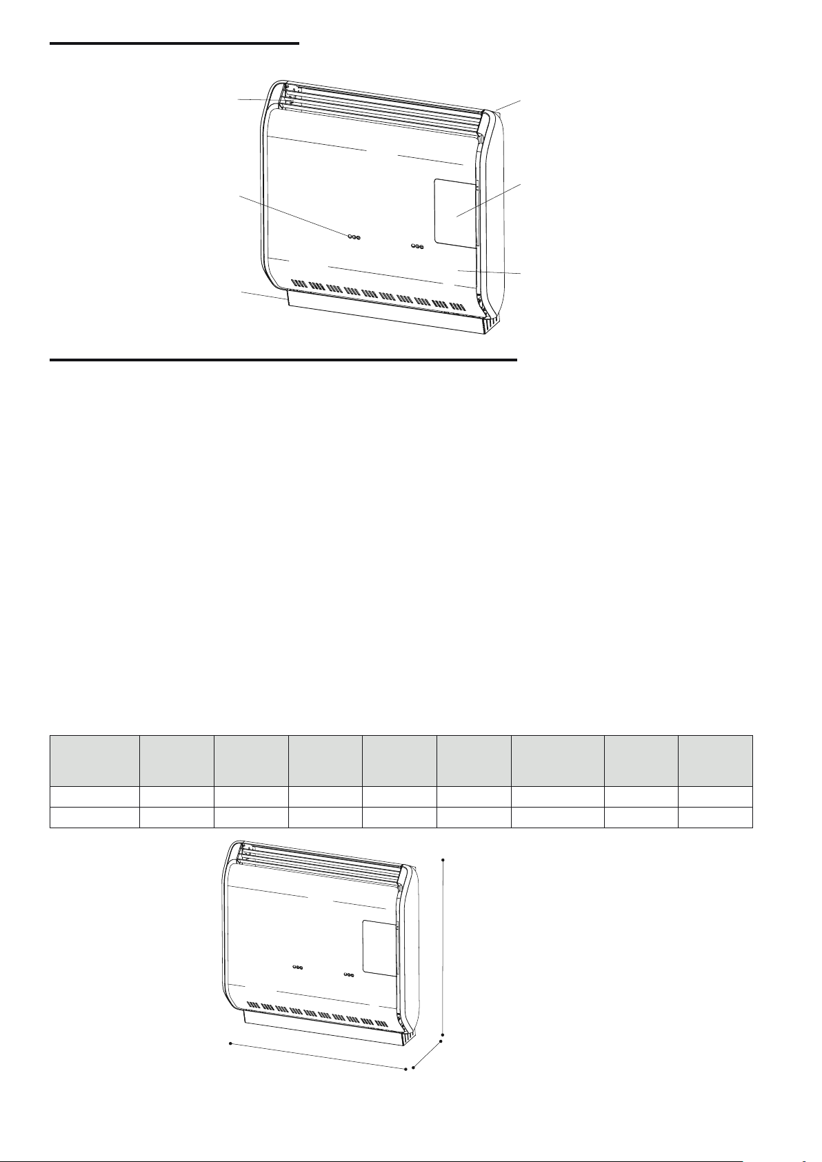
PRODUCT IDENTIFICATION
inspection
Guard
grill
Back
cabinet
Control panel
Burner
door
holes
Front
Blower
cabinet
coverage
SPECIFICATIONS, DIMENSIONS AND ADVERTISING
These units are independent gas appliances for space heating. They use an atmospheric burner with an airtight
combustion chamber. This guarantees maximum safety because it does not allow exhaust fumes or gas leak
in the habited environment. The intake of the combustion air and the exhaust of the combustion fumes takes
place outside the environment through two concentric tubes, thanks to the balanced draft created by the
ascending force of the fumes. They can be installed in narrow spaces and are equipped with a humidifying
tray. They are assembled, in the factory, for operation with Gas "E" (LPG), but can be converted for Gas "A"
(LNG) operation, using the nozzle kit supplied.
The thermostatic ignition/control/regulation valve, controls all main functions and automatically shuts off the
gas supply in case of malfunction.
The control panel allows you to switch on the appliance’s electrical power (appliances with tangential fan or
timer only), to start and stop it manually or automatically using the thermodisc, to set its heating power and
start/stop the fan, adjust the room temperature setting and restore operation after a malfunction.
In Canada, the CSA C22.1 Canadian National Electrical Code and in the U.S.A, the NFPA 70 National Electrical
Code are to be followed in the absence of local code requirement.
Model Input
Nom./Red.
kW
DV30 3,49/1,42 25,27 8,85 33,77 1/2” Gas "E"(LPG) 35,43 5
DV45 5,11/2,04 32,36 8,85 33,77 1/2” Gas "E"(LPG) 35,43 5
A
Width
B
Depth
C
Height
Gas
Connection
Type
gas
MAX wall
thickness
MIN wall
thickness
LNG: Liquefied Natural Gas
LPG: Liquefied Propane Gas
C
Drolet-DG04905 7
A
B
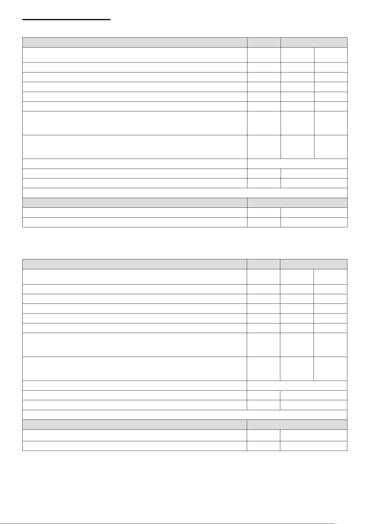
PRODUCT FEATURES
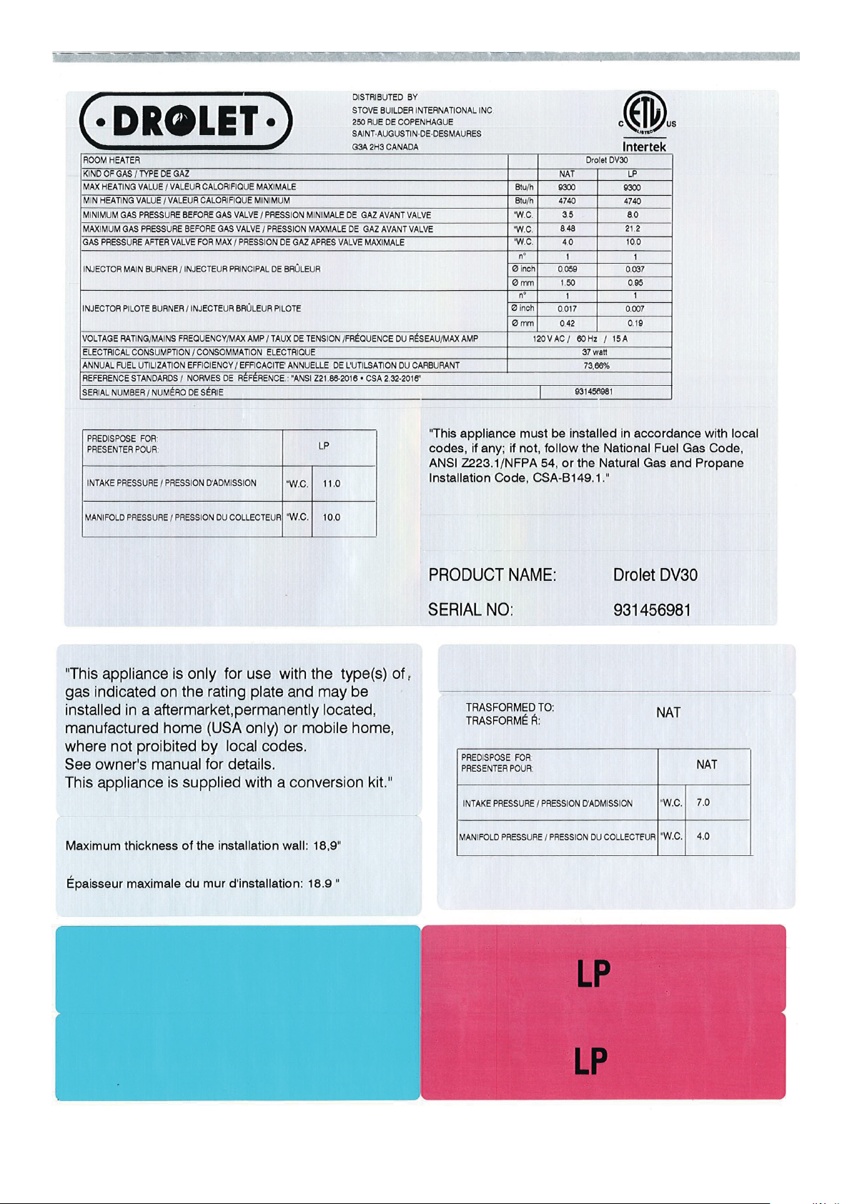
Room heater
Gas type
Max heating value
Min heating value
Minimum gas pressure before valve
Maximum gas pressure before valve
Gas pressure after valve for max
Injector main burner /
Injector pilote burner
Voltage rating / mains frequency
Electrical consumption
Annual fuel utilization efciency
Reference standards "ANSI Z21 86-2016 • CSA 2.32-2016"
Predispose for
Intake pressure
Manifold pressure
DV30
Gas A
(LNG)
Btu 9300 9300
Btu 4740 4740
W.C. 3.5 8.0
W.C. 8.48 21.2
W.C. 4.0 10.0
n.
Ø inch
Ø mm
n.
Ø inch
Ø mm
120 V AC / 60Hz
W/H 37
% 73,66
W.C. 11
W.C. 10
1
0.059
1.50
1
0.017
0.42
GAS E
Gas E
(LPG)
0.037
0.95
0.007
0.19
1
1
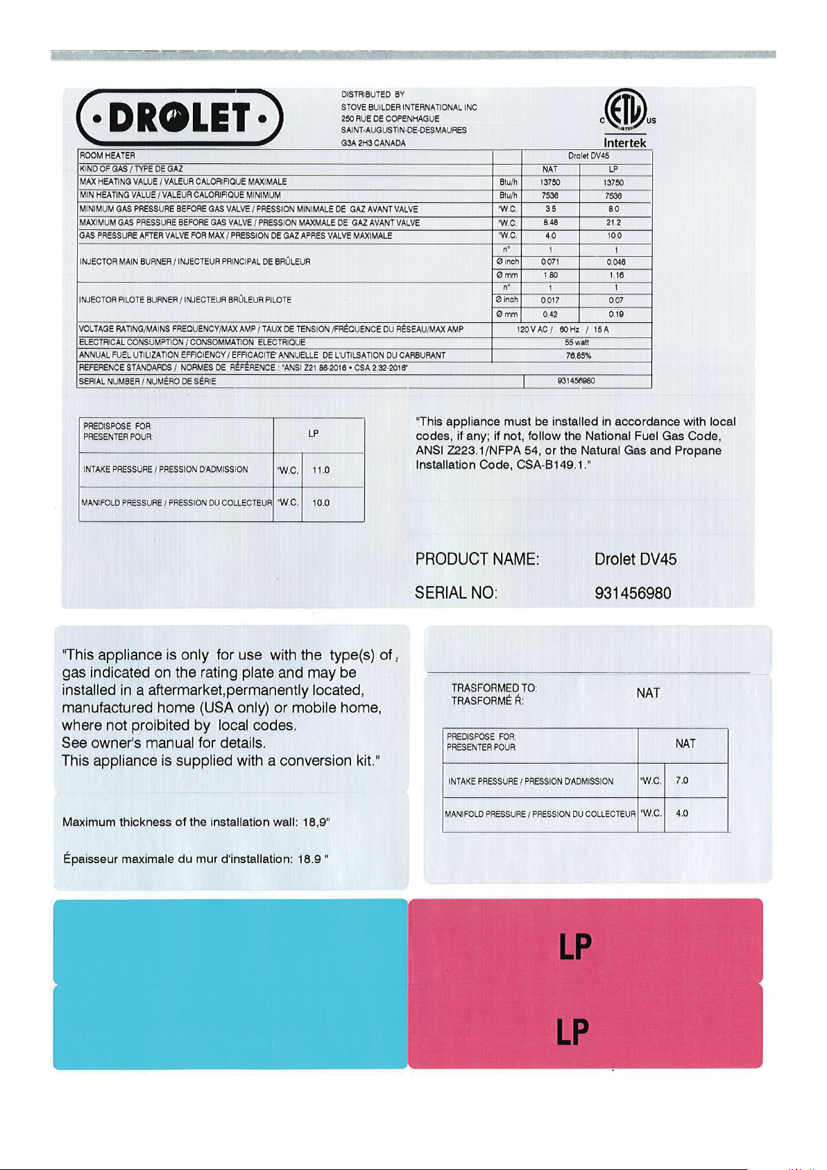
Room heater
Gas type
Max heating value
Min heating value
Minimum gas pressure before valve
Maximum gas pressure before valve
Gas pressure after valve for max
Injector main burner
Injector pilote burner
Voltage rating / mains frequency
Electrical consumption
Annual fuel utilization efciency t
Reference standards "ANSI Z21 86-2016 • CSA 2.32-2016"
Predispose for
Intake pressure
DV45
Gas A
(LNG)
Btu 13750 13750
Btu 7536 7536
W.C. 3.5 8.0
W.C. 8.48 21.2
W.C. 4.0 10.0
n.
Ø inch
Ø mm
n.
Ø inch
Ø mm
120 V AC / 60Hz
W/H 55
% 76,85
W.C. 11
1
0.071
1.80
1
0.017
0.42
GAS E
Gas E
(LPG)
0.046
1.16
0.007
0.19
1
1
Manifold pressure
W.C. 10
NOTE: Minimum Gas Inlet Pressure for purpose of input adjustment.The efciency rating of the appliance is
a product thermal efciency rating determined under continuous operating conditions and was determined
independently of any installed system.
Drolet-DG049058
Verify proper operation after servicing.
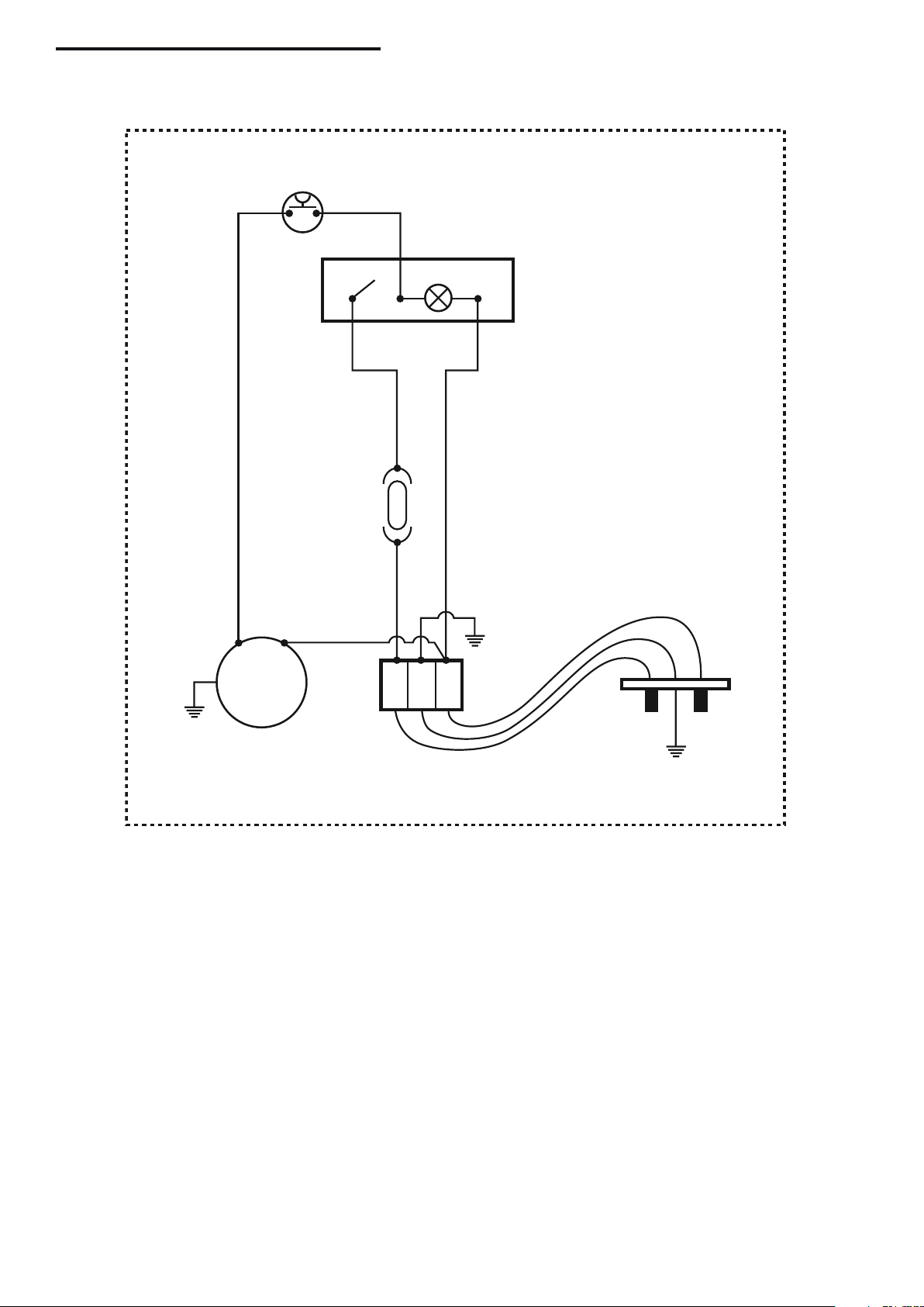
FUNCTIONAL WIRING DIAGRAM
45°
TV
IMP
Ia I
BoS
Ib
F
1A
V.T.
LN
CL
LN
120V~ / 60 Hz
CL LINE CONNECTOR
CVT CONDENSER
EA IGNITION ELECTRODE
F FUSE
IMP MANUAL SWITCH
L PHASE
N NEUTRAL
O TIMER
TV FAN THERMODISC
VT TANGENTIAL FAN
BoS BULB OF SWITCH
CAUTION: Label all wires prior to disconnection when servicing controls.
Wiring errors can cause improper and dangerous operation.
Drolet-DG04905 9
 Loading...