


- S e r i e S B u i l d M a n u a l
Droidworx l t d n e w Z e a l a n d
1

C o n t e n t S
3 Flight operation and safety
4 Operation and Safety
6 Pre-Flight Safety Check
7 Do’s and Dont’s
8 Assembly overview
9 Required Tools
10 Assembly Overview
15 Assembly Instructions
16 Part 1: Landing Gear Assembly
21 Part 2: Center Plate and Boom Assembly Instructions
22 VM(X)4
29 VM 6
32 VM 8
36 VMX3
39 Part 3: Engine Mount Assembly
43 Part 4: Crash Cage Assembly
47 Part 5: Dome Cover Assembly
2

F l i g h t o p e r a t i o n a n d S a F e t y
3

o p e r a t i o n a n d S a F e t y
This is a quick guide for those new to Multi-Rotor craft oering
some basic safety and operational procedures...and are
recommended standard operating procedures for those piloting
Droidworx or any multi-rotor craft.
Please read the instructions for the relevant Flight Control
electronics before proceeding. Go to the web site of your ight
control system and make yourself well acquainted with the correct
procedure for the electronics installation and software operation.
Caution: never connect and start the engines for the rst time with
the propellers attached....and always balance your propellers;
unbalanced propellers can cause excessive vibration which may
lead to material fatigue.
Note: check the orientation of the ight controller you are using
(which way is front) and also the engine assignment conguration;
for instance which is engine 1,2,3 etc. and check also that your
propellers, clockwise and counter clockwise, are also installed
correctly before your rst ight.
Before the rst ight hand test your craft – arm and calibrate your
electronics, hold the craft with both hands by the landing gear
skids above your head with the front facing away from, and to
the front of you, make sure you are well clear of obstructions and
other people. You may need the assistance of another person
for this test. Raise the throttle to around 25% and gently move
the craft around the axis’ roll (tipping the craft left and right) and
feel for a steady and smooth resistance to your movements, do
the same for pitch (tipping the craft forward and backward) and
also yaw, rotating the craft clockwise and anti-clockwise whilst
keeping it horizontal. If the craft oers smooth resistance to your
movements it will y correctly.
Your rst test ight should be in an open eld in low or zero wind.
A sports eld (not currently in use) is a good option; choose a site
with short or mown grass. Do not takeo from dry dusty sites.
Make sure any onlookers or spectators do not gather about you…
if so ask them to move away from you in a perimeter not less than
50m (150 feet) diameter around you.
Make sure that you have fully charged your transmitter and
onboard battery packs. Make sure that the antenna of your Radio
(TX) is up and correctly positioned; make sure the receiver (RX) for
your craft is well positioned within the craft and secured and that
the antenna is facing downward and to the back of your craft and
not touching any part of the craft.
Place the craft on level ground and turn on your transmitter –
check that you have the correct model selected on your TX.
4

Set the transmitter timer to about 80% of the known ight duration.
ask them to stand well clear of you until you have landed.
Connect the battery to your crafts FC inputs and wait for the
engine controller beeps to stop.
Stand about 4m away from your craft and behind the craft with the
craft facing directly away from you.
Check the 50m ight safety perimeter you have established, also
checking behind you for children running in to see what you are
doing.
Survey the area; look for obstacles that you might not have seen
previously, like power-lines and overhead wires.
Never y your craft near a controlled aerodrome or in controlled
airspace.
Check the weather conditions, the wind speed and direction. Do not
y in gusty strong wind at any time. Always try and y the craft with
the wind at your back so the craft will drift directly away from you.
Always keep your eyes on the craft when in ight – if people approach
you inside your safety perimeter to talk to you or to ask questions
whilst you are ying the craft do not engage in the conversation and
Re-check your perimeter and raise the throttle slowly and check to
see if the craft wants to tilt to one direction or another; sometimes
you may need to adjust the trim on your TX to get a level ight,
however most times the craft will y perfectly rst time if you have
installed the electronics and the software has been set correctly—
check with the Flight Control manufacturer for standard or beginner
settings for the craft.
Take os are sometimes easier with a short burst of power to lift the
craft o the ground.
Hold the craft in a controlled hover directly in front of you about 2-3m
o the ground away from “ground eect” prop wash. When you have
mastered this hover position you can then move on to rolling the craft
gently from side to side and forward and backward. Make sure that
you always stand behind the craft, this makes for easy orientation of
the ight controls.
Repeat this exercise several times before you take the craft any
higher.
Always y the craft well away from people and / or property. Always
check for children nearby.
5

p r e - F l i g h t S a F e t y C h e C k
Thoroughly check the craft before every ight…
Check to see if any wires have come o
•
Check for loose bolts on the assembly
•
Check that the battery’s are secure
•
Check the battery voltage, and if you have more than one battery, check your spares too
•
Check the propellers for marks and nicks
•
Check the propeller nuts or bolts, make sure they are tight
•
Check the engine mounts and the bolts and nuts for tightness
•
Check the Transmitter battery voltage; never y the craft with a low voltage reading on your transmitter
•
(check with the manufacturer of your equipment for minimum and maximum voltage readings).
Check that the transmitter antenna is not damaged.
•
Check that the craft receiver module is well connected and that the antenna’s are properly positioned.
•
Take a good look over the craft from all sides to make sure that nothing appears unusual or out of place.
•
Check your ight perimeter.
•
Check for power-lines and overhead obstacles.
•
Assess the weather conditions, wind direction and speed. An anemometer (hand held wind speed meter) is a good tool
•
to have, otherwise use some dry grass or a tissue, throwing in the air to gauge the wind direction.
Do not y in gusty and turbulent conditions.
•
Set your transmitter timer to 80% of the known battery duration.
•
DISCLAIMER:
Droidworx NZ Limited disclaims all warranties, whether express or implied, including but not limited to the implied warranties of merchantability and tness for a particular purpose. Droidworx NZ
Limited does not assume any lyability, whether direct or indirect, from the use of the
VM-Series Craft. Droidworx NZ Limited shall not be liable for any direct, indirect, special, incidental, punitive, contingent or consequential damages to persons or property caused by the VM-Series
craft. In no event shall Droidworx NZ Limited be liable for personal injury up to and including death.
6

d o ’ S a n d d o n t ’ S :
Never y in strong wind – the operational safe wind speed for these craft is about 10-15 KPH.
•
In the event of a crash or a hard landing, always check the craft for damage before taking o again. In this instance, you must also
•
check that you do not have dirt or grit in the engines; this can cause an engine or engines to overheat and fail in ight resulting in an
out of control craft and serious damage or injury to the craft , other people and their property.
Your launch eld should preferably be open and at with short grass. If it is necessary to take o in a eld which only has long grass,
•
manually atten a 1.5m diameter take o perimeter with your feet.
Always have a ight plan – visualize your ight path and check again for obstacles.
•
Never y the craft out of direct line of sight and always keep your eyes on the craft whilst it is in the air.
•
Never y the craft above 400 feet in height (the length of a football eld).
•
Never y near people – A 50m (150 ft) perimeter around and above people is a recommended minimum and operational law in
•
most countries.
Always set your transmitter timer before each ight to about 80% of the known ight duration for the battery pack’s you have installed in the craft.
•
Never turn your transmitter o in ight.
•
First person view ights are against the law in some countries – check the relevant aviation safety authority in your country before ying FPV.
•
Always have a “spotter” with if you do y FPV.
Never let friends y your craft unless they are well schooled in the discipline.
•
Never y under the inuence of any substance or alcohol. Whilst there is a minimum blood alcohol level allowed for driving an
•
automobile in most countries, the law for pilots in command of ying craft around the globe is universal…there is a zero limit tolerance.
Always turn your transmitter on before connecting the battery to the craft...and always disconnect the battery from the craft before
•
turning your transmitter o.
7

a S S e M B l y o v e r v i e w
8

r e q u i r e d t o o l S
M4 7mm Hex Driver
3mm Phillips Head Driver
M3 2.5mm Hex Screw Driver
M3 6mm Hex Driver
M4 3mm Hex Screw Driver
9

a S S e M B l y i n S t r u C t i o n S
10

part 1: landing gear aSSeMBly
11

landing gear aSSeMBly
Product Code Product Code
1402-0010
1402-0020
1402-0030
1402-0050
1406-0030
1406-0040
Gear Rail Bracing Plate
Gear Rail Isolator Pad
Landing Gear Plate
LG Skid End Cap
POV Mount Side Plate
POV Mount Bottom Plate
2
2
2
4
2
1
1406-0130
1406-0145
1406-0200
2503-0030
2506-0020
2506-0170
Gear Rail Bracket
Gear Rail Tube
Landing Gear Skid
Socket Head Cap Screw M3x8mm
Socket Head Cap Screw M3x12mm
Nyloc Nut M3 SS
Parts + SparesParts + Spares
2
6
2
12 (1)
2 (1)
2 (1)
1406-0050
1406-0060
1406-0080
Velcro Strap
Battery Strap
Battery Mounting Plate
1
1
2
2506-0190
2506-0200
2506-0250
Nylon washer M3
Spacer M3x2mm Nylon
Rubber grommet 9.5mm
14 (2)
4
12
12

1
3
2
Fit the four rubber grommets to the polycomposite gear rail brackets as shown.
Fit the four rubber grommets to the
carbon-bre battery plates then feed the
battery strap through the slots and loop.
Slide the battery plates onto the gear
rail tubes as show below.
x4
x2
4
POV Mounting Side Plates
Fit the four rubber grommets to the
pov mount side plates.
x2
x2
x4
x4
13
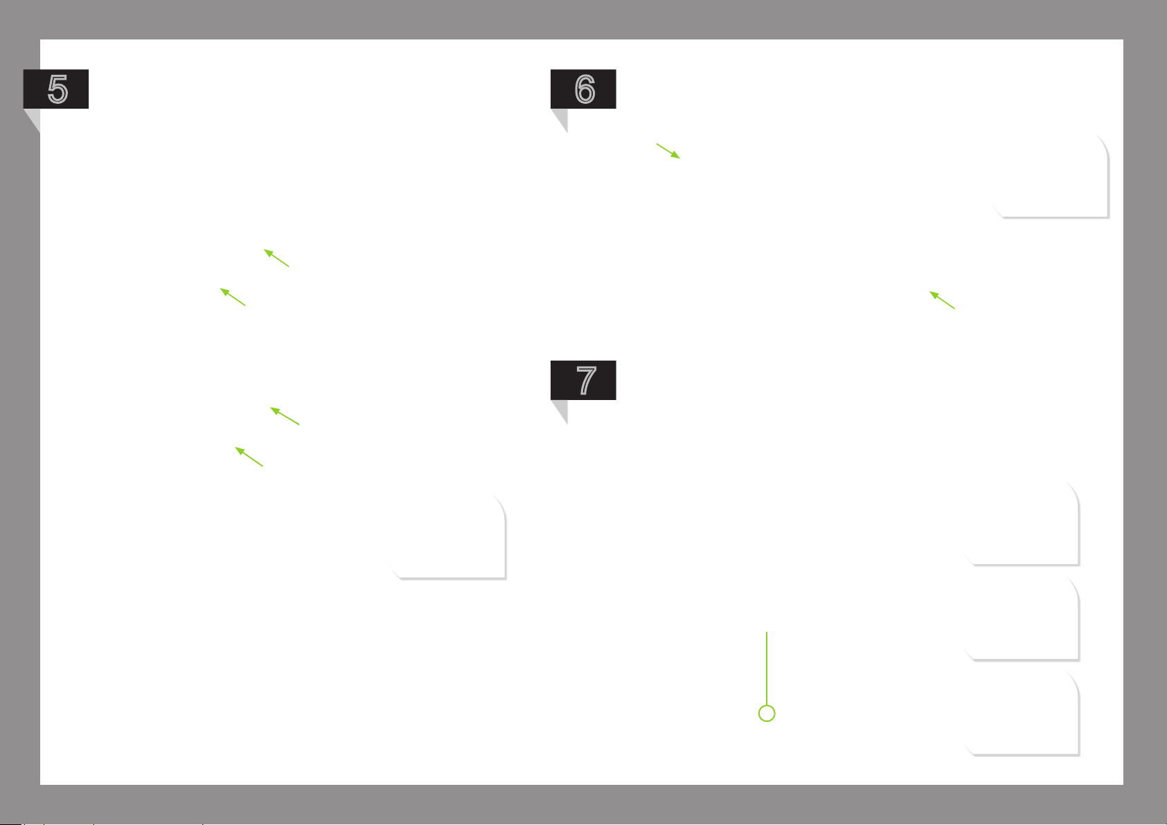
5
Slide the POV mounting plates onto the
gear rail tubes in front of the battery plates.
Adjust the distance between them to t the
POV mount bottom plate (g 1)
Lastly slide the gear rail brackets onto the gear rail
6
tubes ensuring the tabs face inwards and are at the top.
7
Fit the M3 x 12mm screw through the
landing gear plate and add 2 of the
nylon spacers.
g 1
14

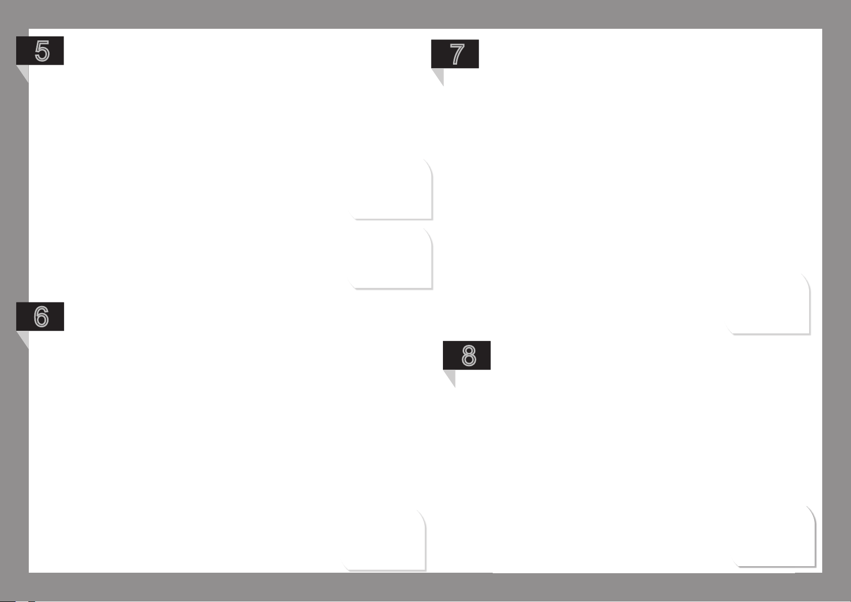
8
9
Pass the M3 x 12mm screw through
the landing gear bracket you set
up earlier and secure with the M3
nyloc nut. This part shouldn’t be fully
tightened until after the landing gear
assembly has been tted to the craft.
x2
10
Attach the four M3 x 8mm screws
through the landing gear plates into
the threaded ends of the gear rail
tubes; place a nylon washer under all
of the screws. Try not to over tighten,
just make rm contact.
NOTE: When tightening
each screw make sure
you secure the opposite
end. Failure to do so
may damage the bond
causing the inner tube
to spin. There is no
functional or structural
disadvantage if this
were to happen - just
secure both ends whilst
tightening.
x4
x4
Repeat steps 4 and 5 with
the second landing gear
plate so your setup looks
like this.
11
The remaining gear rail tubes can now
be attached as landing gear brace
tubes with M3x8mm screws. Place
two on each side at your desired
spacing.
x8
x8
15

12
13
Fit the rubber grommets to the end of the
landing gear main plates and slide the
landing gear skids through. Make sure
that both skids are even with one another.
The nal step is to ax the Droidworx
Landing Gear Sticker to the front
landing gear plate and your setup
should look something like this.
x4
x2
...nally slide the Rubber Cap over all
four skid ends.
16

RETRO FIT XM LANDING GEAR TO YOUR AD/VM CRAFT
Product Code
1404-0094
2504-0010
2505-0250
2506-0170
2506-0490
2504-0030
Universal Landing Gear Mounting Plate
Socket Head Cap Screw M3x40mm
M3X6mm Spacers
Nyloc Nut M3 SS
Socket Head Cap Screw M3x25mm
M3 Locking Washer
Parts + Spares
1
4
4
4
2
2
17

1
2
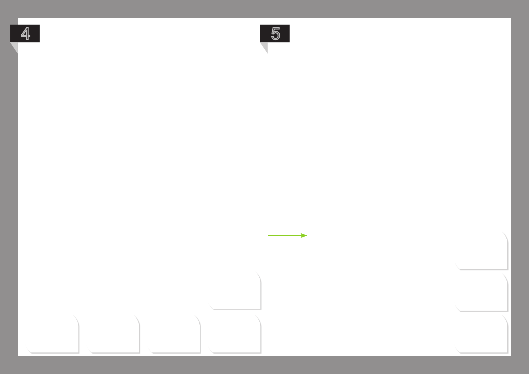
Firstly remove 4 of the inner boom bolts and
replace with the M3x 40mm SS bolts as shown
below. Note where the notch on the center
plate is.
Flip your craft over. Slide the Spacers
onto the ss bolts...
3
...followed by the Universal Landing
Gear Plate.
x4
4
Secure with the M3 Stainless Steel
nuts.
x4
x4
18

5
7
6
Fit your Gear Rail Mounting Bracket using the SS bolts from
the previous Landing Gear. You will need long nose plyers to
attach the SS nuts.
Use M3x12mm Socket head Cap Screws
and M3 Locking Washers on the raised
section of the clip, and M3x8mm Socket
Head Cap Screws and Locking Washers on
the remaining two holes.
Note these parts come with your Landing
Gear Kit.
x2
Your clip fastens to the holes
highlighted below.
8
The orientation of your clip should
look like this.
x2
x4
19

9
11
10
Build your Landing Gear and Gear Rail Assembly as shown
in the corresponding sections.
Always clip on from left to right.
Once snapped in place your Landing Gear
can be further secured by inserting the
M3x25 SS Socket Head Cap Screw with
Locking washer as shown here.
x2
x2
20

12
Your nal setup should now look like this...
21

p a r t 2 : C e n t e r p l a t e a n d B o o M a S S e M B l y i n S t r u C t i o n S
21

v M - 4
Product Code Product Code
1202-0010
1202-0040
1206-0010
1206-0044
1206-0064
1504-0010
Center Plate
Decal set VM
Universal Adaptor Plate
Boom bracket inner
Boom bracket outer
Gear Rail Center Plate Spacer M3
2
1
1
(1)
8
(1)
8
8
2503-0070
2506-0050
2506-0060
2506-0140
2506-0170
1306-0011
Stando Threaded M3x11 Nylon
Socket Head Cap Screw M3x30mm
Socket Head Cap Screw M3x35mm SS
Machine Screw M3x6mm Pan Philips
Nyloc Nut M3 SS
Boom 310mm
Parts + SparesParts + Spares
16
20
4
(1)
4
(1)
8
(2)
4
22

1
Take a moment to familiarise yourself
with the centre plate setup to get an
understanding which holes relates to
which parts. Take one of the plates
and lay it out with the notch at the top
and the sticker facing up.
NOTE: It is important that you install
the standos for your electronics
BEFORE mounting the booms as you
will not be able to reach the required
holes afterwards.
Lines indicate the boom
mount triangle pattern
used for all models.
Circles show the
holes used for dome
xing.
Squares represent the remaining holes
you can attach the standos to. This
is all dependent on which electronics
you will be using. In this guide we
will demonstrate how to attach the
Universal Adapter Plate we send with
all of our crafts.
23

2
Slot the M3x30mm bolts into the relevant holes for boom
mounting shown by the yellow triangles. Then ip the plate
over (bottom picture).
x12
3
4
Slide the inner and outer boom brackets onto the
corresponding bolts.
x4
x4
Mount your booms onto the brackets as
shown here. The holes closest to the end of
the Booms should face inwards.
NOTE: For this model the
curve of the boom brackets
face inward following the
curvature of the plate.
24
5
Place the remaining boom bracket inners and
outers onto the booms.
x4
x4
7
7
Fit M3 SS nuts to the screws - do not
tighten them, just make them secure
whilst you work your way around.
66
Position the second centre plate over the boom cluster
aligning the hole pattern as shown below.
78
x12
Now t the 22mm center plate spacers
between the center plates as shown below
using the M3x35mm SS screws for front
and back of the craft (your landing gear
will attach to these) and the M3x30mm for
left and right spacers.
x8
25

9
10
You can now tighten all of the nuts
apart from the SS ones (front and
rear).
Fit the electronics standos by
slotting the supplied nylon M3 x
6mm countersunk screws through
the desired holes from the underside.
Then screw the standos onto them.
x4
x4
26

11
Now place your universal ight
controller adapter plate onto the
stando and secure with the M3x6mm
nylon screws as shown below.
Note: the small notch on the adaptor
plate should face to the front.
x4
27

12
Your setup should now look like this....
28

v M 6
Product Code Product Code
1202-0020
1202-0040
1206-0010
1206-0044
1206-0064
Center Plate
Decal set VM
Universal Adaptor Plate
Boom bracket inner
Boom bracket outer
Parts + Spares
2
1
1
(1)
12
(1)
12
2503-0070
2506-0050
2506-0060
2506-0140
2506-0170
1306-0011
Stando Threaded M3x11 Nylon
Socket Head Cap Screw M3x30mm
Socket Head Cap Screw M3x35mm SS
Machine Screw M3x6mm Pan Philips
Nyloc Nut M3 SS
Boom 310mm or 355mm
Parts + Spares
4
(1)
14
4
(1)
8
20
6
29

1
The notch indicates the front of the craft.
Take a moment to familiarise yourself
with the centre plate setup to get an
understanding which holes relates to
which parts. Take one of the plates
and lay it out with the notch at the top
and the sticker facing up.
NOTE: It is important that you install
the standos for your electronics
BEFORE mounting the booms as you
will not be able to reach the required
holes afterwards.
Circles show the holes used
for dome xing.
Lines indicate the boom mount triangle
pattern used for all models.
Squares represent the remaining holes
you can attach the standos to. This is all
dependent on which electronics you will
be using. In this guide we will demonstrate
how to attach the Universal Adapter Plate
we send with all of our crafts.
30

2
To build the VM6 core is exactly the
same as the VM4, except there are no
spacers required.
31

v M 8
Product Code Product Code
1202-0030
1202-0040
1206-0010
1206-0044
1206-0064
Center Plate
Decal set VM
Universal Adaptor Plate
Boom bracket inner
Boom bracket outer
Parts + Spares
2
1
1
(1)
16
(1)
16
2503-0070
2506-0050
2506-0060
2506-0140
2506-0170
1306-0011
Stando Threaded M3x11 Nylon
Socket Head Cap Screw M3x30mm
Socket Head Cap Screw M3x35mm SS
Machine Screw M3x6mm Pan Philips
Nyloc Nut M3 SS
Boom 355mm or 410mm
Parts + Spares
4
(1)
20
4
(1)
8
(2)
24
8
32

1
The notch indicates the
front of the craft.
Take a moment to familiarise yourself
with the centre plate setup to get an
understanding which holes relate to
which parts. Take one of the plates
and lay it out with the notch at the top
and the sticker facing up.
NOTE: It is important that you install
the standos for your electronics
BEFORE mounting the booms as you
will not be able to reach the required
holes afterwards.
Circles show the holes
used for dome xing.
Lines indicate the boom
mount triangle pattern
used for all models.
Squares represent the remaining holes
you can attach the standos to. This
is all dependent on which electronics
you will be using. In this guide we will
demonstrate how to attach the Universal
Adapter Plate we send with all of our
crafts.
33

2
To build the VM8 core is exactly the same as the
VM4, except there are no spacers required.
34

3
Your setup should look like this before
attaching the top center plate (follow
instructions from VM4 Core Assembly
chapter).
NB: Placement of SS screws.
35

p a r t 4 : e n g i n e M o u n t a S S e M B l y
36

p a r t 3 : e n g i n e M o u n t a S S e M B l y
Product Code Product Code
1206-0080
1206-0090
1210-0040
2506-0010
Engine Mount Bracket M3 (13mm)
Engine Mount Bracket M3 (20mm)
Engine Mount Disk M3
Heat Shrink Black
2
2
1
1
2506-0050
2506-0120
2506-0170
2504-0030
2510-0080
Socket Head Cap Screw M3x30mm
Machine Screw M3x6mm SS
Nyloc Nut M3 SS
Locking Washer M3
M3 Washer SS
Parts + SparesParts + Spares
2
4
2
2
2
37

1
Apply the heat shrink.
3
Fit the two M3 x 30mm alloy screws,
Locking Washers and Flat Washers
through Engine Mount Bracket
x2
x2
2
Ax the engine to the engine mount disk by slotting the
desired machine screws through the chamfered side of the
disk and into the rewall mount holes of the engine.
x2
4
Place the Boom onto the Engine Mount Bracket making
sure the dimpel slots into the hole of the boom.
x4
38

NOTE: If you plan to Upgrade your craft
with Boom Nacelles to reduce bueting
follow the instructions below before
further mounting the engines.
1
Slide the 1.5mm O-rings over the
boom... adjust the distance of the two
O-rings to t the Boom Nacelle.
2
Place the second half of the Nacelle
on top and snap together.
Please Note: we are showing the
hi visibility boom nacelles in these
pictures. To buy your hi visibility boom
nacelles go to www.droidworx.co.nz
x2
39

5
7
6
Place a second Engine Mount Bracket on top, feed your wires
through the boom and place the Engine Mount Disk with the
engine on top.
Fasten with M3 SS Nyloc Nuts.
Your nished setup should now look
like this...
x2
40

p a r t 4 : C r a S h C a g e a S S e M B l y
Product Code Product Code
1102-0032
1102-0040
1106-0050
1110-0010
1506-0060
2503-0030
Crash Cage Outer Mounting Ring
Crash Cage Hub
Crash Cage Arch
Crash Cage Mounting Bracket
Top Mounting Post
Socket Head Cap Screw M3x8mm alloy
Parts + Spares
1
2
10
5
4
5
2506-0140
2506-0170
2506-0190
2506-0210
2506-0260
2506-0460
Machine Screw M3x6mm Pan Philips
Nyloc Nut M3 SS
Nylon Washer M3
Nylon Spacer M3x10mm
Dome Grommet
Nyloc Nut M3 alloy
Parts + Spares
5
12
(1)
12
(2)
10
(1)
4
5
(1)
2506-0030
Socket Head Cap Screw M3x20mm alloy
11
(1)
41

1
2
Assemble the 5 spokes by using 2
arches, one M3x20mm socket head
cap screw, 1 washer, 1 nyloc nut and
1 spacer per setup as shown in the
picture below.
x2
3
Repeat step 1 for all 5 spokes of the
Crash Cage.
Using a M3x20mmm socket head
cap screw, washer and a nyloc nut,
join the 2 Hubs together, leaving them
loose enough to slide the arches into
the corresponding slots of the Hub as
shown in the picture below. You may
now tighten the nut. Make sure you do
not overtighten as this may warp your
hub.
x2
x2
42
4
Assemble the outer mounting ring
using the M3x8mm alloy socket head
cap screws, M3 Nyloc Nuts, alloy
mounting bracket and the dome
grommets as shown in the pictures
below.
5
Take the assembled Crash Cage Arch
and place onto the corresponding
mounting ring brackets making sure
the arches go inside the bracket, using
the M3x20mm bolt and the M3 alloy
nut and fasten as shown here.
x5
x5
x5
x4
x5
x5
x5
43

6
Firmly press the assembled outer
mounting ring onto the dome mounting
posts of the center plate of your craft.
To attach / remove your Crash cage to / from your VM Craft place
ngers on each side of the mounting post and press rmly.
Your VM Craft should now look like this.
44

p a r t 5 : d o M e C o v e r a S S e M B l y
Product Code
1106-0010
1506-0060
2506-0140
2506-0260
Dome
Top Mounting Post
Machine Screw M3x6mm Pan Phillips
Dome Grommet
Parts + Spares
1
4
5
(1)
4
45

1
Attach the four dome mounting posts
to the center plate of your craft as
shown in the picture below.
2
Fit 4 of the rubber grommets to the
dome as shown.
x4
46

5
Firmly press the dome onto the top of
the craft aligning the grommets with
the corresponing dome mounting
posts.
To attach / remove your Crash cage
to / from your VM Craft place ngers
on each side of the mounting post and
press rmly.
47

5
Your setup should now look like this.
48
 Loading...