

Dr. Livingstone, I Presume WELDWISE 2400 User Manual
Use
s
a
ual
T
THE WELD MONITORING SPECIALISTS
WeldWise 2400
M
r’
Revision C.001
M
n


Disclaimer
Livingston & Company makes no warranty of any kind with regard to this material, including, but not
limited to, implied warranties of merchantability and fitness for a particular purpose.
Livingston & Company shall not be liable for errors contained herein or for incidental consequential
damages in connection with the furnishing, performance or use of this material.
Copyright
This document contains proprietary information that is protected by copyright. All rights are reserved.
No part of this document may be photocopied, reproduced or translated to another language without
the prior written consent of Livingston & Company. The information contained in this document is
subject to change without notice.
© 2007 Livingston & Company
All rights reserved.
0453-INS-400 Rev. F
i

Product Road Map
The Livingston User's Manual includes the following sections:
• Overview of Resistance Welding: Explains the fundamentals of resistance welding and factors
that affect the quality of resistance welds
• Introduction to Resistance Weld Monitoring: Explains the fundamentals of resistance weld
monitoring and reasons for weld monitoring
• Tolerancing & Monitoring: Describes Livingston's concept of resistance weld monitoring and
terminology used regarding Livingston equipment
• Getting Familiar With the WeldWise™ 2400: A brief physical overview of navigating with the
software
• WMS Quick Start: A basic how-to guide to weld monitoring with Livingston equipment
• WMS Reference Guide: A complete software reference to the Livingston Weld Monitoring
Software (WMS) program
• Installing the Sensors: Describes the various types of sensors available for use with Livingston
weld monitors and installation guidelines
• Calibrating the Sensors: Explains how to calibrate sensors using the WMS program
• FAQ: Includes answers to frequently asked questions
• Troubleshooting Guide: A beginner's guide to basic troubleshooting for Livingston systems
• Appendices: Includes information reprinted from the RWMA, and various subject matter
pertaining to both Livingston equipment and software.
• Application Notes: Includes general 'how-to' procedures and notes relating to software and/or
hardware issues
• Contact Information: How to reach Livingston
ii 0452-INS-400 Rev. C

Table of Contents
OVERVIEW OF RESISTANCE WELDING 1
INTRODUCTION 1-1
VARIABLES IN THE WELDING PROCESS 1-2
THE WELD CYCLE 1-2
CRITICAL FACTORS IN WELDING 1-3
CURRENT 1-3
VOLTAGE 1-3
POWER 1-4
RESISTANCE 1-4
ELECTRODES 1-4
SURFACE CONTACT 1-6
CURRENT DENSITY 1-6
OHM'S LAW AND JOULE'S LAWS 1-7
IDENTIFYING AND CORRECTING WELD PROBLEMS 1-8
RECOMMENDATIONS FOR PRODUCING QUALITY WELDS 1-9
AVOID THESE POTENTIAL SOURCES OF WELD PROBLEMS 1-10
INTRODUCTION TO RESISTANCE WELD MONITORING 2
INTRODUCTION 2-1
WHY MONITOR? 2-1
WELD LOBES AND THE WELD PROCESS 2-2
STYLES OF MONITORING 2-2
BEFORE & AFTER MONITORING 2-2
MASS MONITORING 2-3
DYNAMIC MONITORING
2-3
EFFECTS OF DIFFERENT FACTORS 2-4
HOW MONITORS WORK 2-5
MORE BENEFITS 2-5
TOLERANCING AND MONITORING 3
INTRODUCTION 3-1
LIVINGSTON WELDWISE MONITOR 3-1
SIGNATURES & MASTERS 3-1
TOLERANCES 3-2
MEASURED PARAMETERS 3-3
SEGMENTS 3-3
DATA COLLECTION 3-4
0427-INS-400 Rev. D
iii

GETTING FAMILIAR WITH THE
WELDWISE™ 2400 4
THE FRONT PANEL 4-1
WMS NAVIGATION AND EDITING 4-2
NAVIGATION 4-2
EDITING 4-2
OTHER BUTTONS 4-3
THE BACK PANEL 4-4
PROPER SHUTDOWN PROCEDURE 4-5
WMS QUICK START GUIDE 5
GENERAL SETUP 5-1
GATHERING DATA 5-2
CREATING A MASTER 5-7
ACCEPTING / REJECTING WELDS 5-8
TOLERANCING 5-10
SUMMARY 5-11
WMS REFERENCE GUIDE 6
MAIN PROGRAM SCREEN 6-1
MAIN MENU OPTIONS 6-4
DATA MENU OPTIONS 6-5
HALFCYCLE SUMMARY SCREEN 6-6
WELD SUMMARY SCREEN 6-11
SYSTEM LOG SCREEN 6-12
DATABASE MANAGEMENT 6-13
DATABASE IMPORT SCREEN 6-16
DATABASE EXPORT SCREEN 6-18
SCOPE DATA SCREEN 6-20
MASTERING SCREEN 6-21
EDIT MASTER SCREEN 6-24
TOLERANCING SCREEN 6-25
SETUP MENU 6-30
GENERAL SETUP 6-31
SETUP UTILITIES 6-38
INPUT MONITOR 6-39
TOROID SETTINGS UTILITY 6-40
VOLTAGE CALIBRATION UTILITY 6-41
FORCE CALIBRATION UTILITY 6-42
DISPLACEMENT CALIBRATION UTILITY 6-43
TOLERANCE DEFAULTS SETUP 6-44
0427-INS-400 Rev. D
iv

GRAPH SETUP 6-45
SHUTDOWN MENU 6-46
INSTALLING THE SENSORS 7
TYPES OF SENSORS 7-2
CURRENT 7-2
VOLTAGE 7-2
FORCE 7-2
DISPLACEMENT 7-3
INSTALLING THE CURRENT TOROID 7-4
INSTALLING THE VOLTAGE LEADS 7-5
INSTALLING THE FORCE SENSOR 7-6
INSTALLING THE DISPLACEMENT SENSOR 7-7
TESTING SENSOR INSTALLATION 7-8
CALIBRATING THE SENSORS 8
IMPORTANT NOTES 8-1
FREQUENCY OF CALIBRATION 8-1
THE INPUT MONITOR 8-2
INSTALLING/SWAPPING TOROIDS 8-3
PERCENTAGE ADJUSTMENT 8-4
CALIBRATING DISPLACEMENT 8-5
ZEROING THE DISPLACEMENT 8-5
CALIBRATING FORCE 8-6
CALIBRATING VOLTAGE 8-8
FREQUENTLY ASKED QUESTIONS 9
TROUBLESHOOTING GUIDE 10
APPENDICES 11
WMS ROAD MAP 11-1
RECOMMENDED DATABASE MANAGEMENT 11-2
IMPORTING/EXPORTING TABLES 11-8
DISPLACEMENT CHANNEL OVERVIEW 11-10
SENSOR CALIBRATION UTILITIES OVERVIEW 11-11
IDENTIFYING AND INTERPRETING STATUS CODES 11-12
ATTACHING PERIPHERALS 11-14
INTERLOCK INTERFACE 11-18
BINARY SELECT & ACCEPT/REJECT TIMING 11-19
WELDWISE™ 2400 SPECIFICATIONS 11-20
0427-INS-400 Rev. D
v

COMMON USES OF RWMA MATERIAL 11-21
WARRANTY & REPAIR POLICY 11-23
APPLICATION NOTES 12
APP NOTE 118 – Changing WeldWise™ 2400 Identification and IP address 12-1
APP NOTE 121 – Copy weld data and use it to create an MS Excel chart 12-7
APP NOTE 307 – Replacing a Pod 12-21
CONTACT INFORMATION 13
0427-INS-400 Rev. D
vi

Overview of Resistance Welding
Introduction
In simplest terms, welding is a process by which two or more pieces of metal are joined by applying
heat and pressure. Back in the good old days, blacksmiths and other crafty people would heat metals in
a furnace and then weld them by hammering the red-hot metals together. By hammering the metals as
they cooled, the weld would be made stronger. This heating-and-hammering method is known as forge
welding. While forge welding worked quite well for most of the welding done back then, today's
welding requirements are a bit more advanced. After all, it would be pretty difficult to heat all the
metal needed to build an automobile in a big factory furnace and expect workers to hammer together
each specific part used in the manufacturing process. We'd all still be riding horses to work!
Fortunately, there are always a handful of brilliant people throughout history who are kind enough to
invent newer, faster, and better ways of doing things. One of these people was a professor by the name
of Elihu Thompson. Sometime in the year 1885, Professor Thompson invented a process called electric
resistance welding. He discovered that to weld metals together, one could fire an electric current
through the metals while they were tightly clamped together. When the current passed through the
metals, it would create such a high heat that the metals would melt and run together and a weld would
be made. Many times, the welded metal would be even stronger than the original metals used in the
welding process.
Today's resistance welders work almost exactly the same way they did when Thompson invented the
process. The current is generated by a transformer, and is fired through electrodes, which hold the
metal pieces in place. These electrodes also apply force to the metal pieces, usually before, during, and
after the firing of the electric current. This method is called resistance welding because it is the
resistance between the contact surfaces of the metals being welded that generates the heat to fuse them
together.
Resistance is the opposition that a substance offers to the flow of electric current. The less resistance a
metal has, the less heat is generated when current passes through it. Conversely, the higher the
resistance of a metal, the more heat is generated when that same current passes through it. This
behavior can be paraphrased as follows: the heat is where the resistance is, and the resistance is where
the heat will be. Obtaining the best results in resistance welding requires a thorough understanding of
the materials being welded, careful control of the heat and pressure at the weld point, and consideration
of numerous other factors. This chapter will deal with the basics of resistance welding, the variables
involved, and why they're so important to the welding process.
0428-INS-400 Rev. E 1-
1
Variables in the Welding Process
The many variables involved in welding can be broadly categorized into two basic sections: process
variables and material variables.
Process variables include: Material variables include:
• Weld current • Coating thickness and type
• Squeeze time • Part fit-up
• Weld time
• Hold time
• Electrode force
• Design of the electrode
• Workpiece material
• Surface condition & cleanliness of
materials
The Weld Cycle
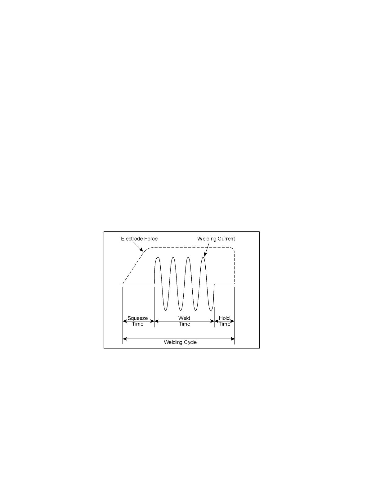
A typical resistance weld is broken down into several distinct periods, as shown in figure 1-1 below:
Figure 1-1 A typical weld cycle
The Squeeze Time is when the weld heads (electrodes) come together and build up to a specified
amount of force before the current is fired.
The Weld Time is when the current is actually passing through the workpieces. This is when the
metals are being heated enough to melt and fuse together to form what is called a weld nugget.
0428-INS-400 Rev. E
1-2

During the Hold Time, electrode force is still applied, even after the weld current has ceased. During
this period, the weld nugget cools and the metals are forged under the force of the electrodes. The
continuing electrode force helps keep the weld intact until it solidifies, cools, and the weld nugget
reaches its maximum strength.
Critical Factors in Welding
Understanding the resistance weld process requires an understanding of the main factors involved and
how they work together. This section will review current, voltage, resistance, and power, as well as the
various functions of the electrodes and how they affect surface contact and current density.
Current
Current, usually measured in Kilo-Amperes (KA — one Kilo-Amp is equal to 1,000 Amps), is one of
the most important factors. A resistance weld cannot be made unless there is sufficient weld current.
According to the RWMA, the typical amount of current needed to weld low-carbon steel, for example,
is about 10,000 Amps (10 KA) at about 5 Volts. To put this in perspective, a normal household or
office outlet provides a maximum of 15-20 Amps (0.015-0.020 KA) at 120 Volts, while a power
circuit in a factory may only be capable of providing 200 Amps (0.200 KA) at 500 Volts to a welder.
The factory's 200 Amps is then converted to the 10,000 Amps needed to weld by means of a welding
transformer.
A transformer consists of two coils of wire, called the primary and the secondary, wound around an
iron core. Power is transferred from primary to secondary via the magnetic properties of the iron. The
factor by which the current and voltage is stepped up or down is equal to the ratio between the number
of turns of wire in the coils forming the primary and secondary windings of the transformer. Consider
the steel that needs 10,000 Amps (10 KA) of current to be welded in a factory that can only provide
200 Amps (0.200 KA). If the welding transformer had 100 turns on the primary and 2 turns on the
secondary, the 'turns ratio' would be 100 to 2, or more simply, 50 to 1. The 200 Amp current in the
primary would then be converted (stepped up) to 10,000 Amps (200 Amps x 50 turns = 10,000 Amps)
in the secondary, which would yield enough amperage to make a weld.
Voltage
If current is the amount of electricity flowing, then Voltage (measured in Volts) is the pressure or force
that's causing the flow. A good analogy is water flowing through a pipe. A larger voltage will result in
greater water pressure, which will cause more water (current) to flow through the pipe. Using the
transformer example above, after the 200 Amps at 500 Volts on the primary passes through the
transformer coils, the secondary amperage increases to 10,000 Amps, but the voltage actually drops to
10 Volts. This decrease in voltage occurs because the amount of power coming out of a transformer
isn't actually increased, but more accurately exchanged.
0428-INS-400 Rev. E 1-
3

Power
Power is Voltage multiplied by Current, and is measured in Watts, or KVA (KVA stands for KiloVolt-Amperes. Watts and KVA will be used interchangeably in this text). This means that the amount
of current flowing times the pressure that's causing it to flow equals the amount of power generated. A
basic law to bear in mind is that the power going into a transformer will always equal the power
coming out of it. Returning to the transformer example, 200 Amps coming in at 500 Volts (200 x 500
= 100,000 KVA) on the primary with a 50 to 1 turns ratio in the transformer will be converted into
10,000 Amps at 10 Volts (10,000 x 10 = 100,000 KVA) going out. As the math illustrates, the results
are the same. The initial and final amperage and voltage may be different, but because the ratio is the
same, the total amount of power is also the same.
Resistance
As mentioned earlier, resistance is defined as the opposition that a substance offers to the flow of
electric current. Resistance is calculated by dividing the Voltage by the Current, and is measured in
Ohms. (When written, Ohms are represented by the Greek letter Omega: Ω). Since resistance to the
current is what generates the heat in the workpiece, it is critically important that the area with the
greatest resistance be at the interface between the two parts being joined. This interface is also known
as the faying surfaces. Remember that the heat is where the resistance is, and the resistance is where
the heat will be. If the area with the most resistance is, for example, where the lower bus bar connects
to the transformer of the welder and not at the faying surfaces of the workpieces, then that's where the
heat will go. Likewise, if the greatest resistance is at the contact area between the electrode tip and the
workpiece, the heat generated there will cause the tip to weld directly to the workpiece.
Electrodes
Typically made of copper alloys, electrodes actually have three separate functions: to conduct current
to the workpieces being welded, to transmit the proper pressure or force to those workpieces to
produce and forge a good weld, and to help dissipate heat from the area being welded. To ensure that
all three of these functions are executed properly, it is important to regularly maintain the electrodes,
keeping them clean and in good condition. A reprint of an RWMA chart describing various types of
electrode materials and their different uses may be found in Chapter 11, APPENDICES, of this
manual.
Conducting Current
The first of these functions is purely electrical— fire weld current through the workpiece. Taking into
account the relationship among current, voltage and resistance, it becomes important to pay attention to
the type of electrodes used. For example, it wouldn't be wise to select electrodes made entirely from a
high resistance material, since they would get so hot they'd melt before the current even had a chance
to flow to the workpiece. It is also important to make sure that the electrodes are the right size for the
application; proper electrode sizing is largely dependent on the amount of force being used on the
workpieces.
Transmitting Force
The second function of the electrodes is mechanical. The amount of force needed to make a good weld
varies, depending on the type of metal being welded and other factors, but a general figure would be
about 600-800 lbs. Because electrodes are typically on the small side— roughly from about the size of
0428-INS-400 Rev. E
1-4
an acorn to the size of a plum, it is also important to choose electrodes that are able to withstand the
force needed to make a good weld.
A key point to understand is that force and resistance have an inverse relationship: more force will
result in less resistance, and vice-versa. The equation has to do with surface contact, which refers to the
specific area on the workpieces touched by the electrodes. Surface contact will be covered further in
the next section, but the following example will begin to illustrate this relationship: if you examine
your fingertip under a magnifying glass, what first appears to be a smooth surface is actually a mass of
rough-looking ridges and bumps. The same is true of electrodes and workpieces. The tips of the
electrodes and the surfaces of the workpieces may look to be smooth and in good condition, but in
reality their surfaces are quite rough, especially if the electrodes are old and worn or if the workpieces
are dirty. By applying pressure to these rough surfaces, any microscopic inconsistencies (e.g., dirt or
grease on the workpiece and/or pits and cracks in the electrodes) are compressed and the surface
actually evens out. This results in improved (increased) surface contact between the electrode tips and
the workpiece, and between the workpieces themselves. When the surface contact is increased, current
can flow more readily from the tips through the workpieces, which means that the resistance has been
lowered.
Force also is what helps to keep the weld intact as it's being formed. As the current generates heat, the
workpiece metal begins to melt. A good analogy to this process is a child eating a popsicle on a hot
summer day. When the popsicle melts, it doesn't remain on the stick― it drips everywhere. When
metal melts it wants to do the same thing, however because it's molten metal and not a runny popsicle,
it doesn't simply drip. It explodes out of the workpiece. This is why proper weld force is so important:
it literally forces the molten metal to stay put, so it can then cool to form a weld nugget. Without
sufficient force, the metal will do what it wants to do, which is what causes expulsion. Expulsion is
nothing more than little pieces of molten metal exploding out of the weld because they're not being
properly held in. The problem with expulsion is that all the metal flying out of the weld is metal that's
not going in to the weld; a weld cannot be made stronger by removing metal from it. Determining the
proper amount of force is entirely application dependent. The RMWA can be contacted for additional
recommendations and guidelines.
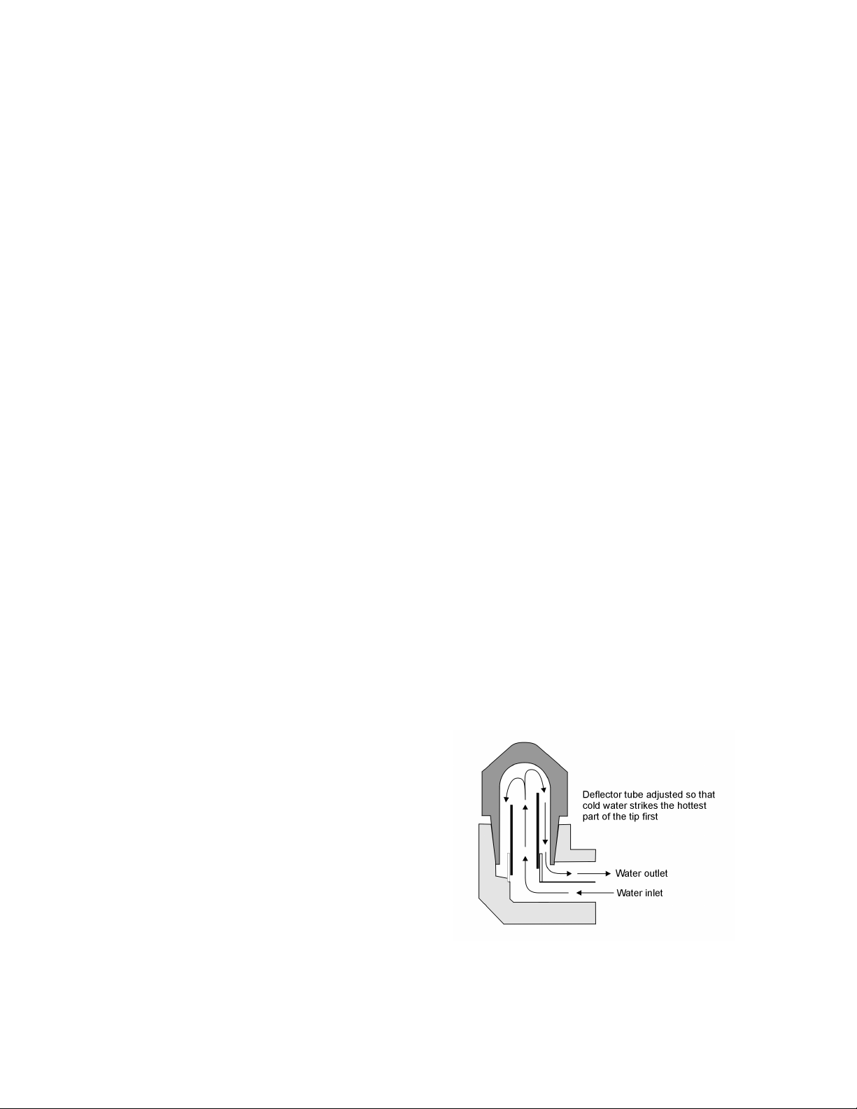
Cooling the Workpiece
Electrodes get considerably hot with 10-20 KA or
more repeatedly flowing under hundreds of pounds
of force. Although most welders have an internal
water cooling system that allows water to circulate
through the tips of the electrodes while welds are
being made, a common problem is a lost, damaged or
improperly sized cooling water tube. Without
anything to cool off the tips, heat can quickly build
up to the point where the electrodes will eventually
weld to the workpieces. To correct this problem, the
water tube should be placed so that the incoming
cold water strikes the hottest part of the tip first, as
shown in figure 1-2.
Figure 1-2 Example of an electrode cooling
channel.
0428-INS-400 Rev. E 1-
5

Surface Contact
The ultimate goal of the weld process is for the weld current to generate sufficient heat between the
workpieces being welded so that the metal will melt, fuse together and form a weld nugget. For this to
happen, the surface contact must be maximized. The following experiment may sound silly, but proves
an important point: take a piece of Scotch tape and stick it to a clean piece of paper. Assuming that the
tape was clean beforehand, it probably sticks very well. Now sprinkle some salt on the piece of paper.
Stick another piece of tape to the paper with the salt on it. Depending on how much salt is there, the
tape probably sticks somewhat to not at all. Lastly, stick a third piece of tape to some carpeting, then
pull it off. Now try to stick that same tape to the paper. The third piece probably doesn't stick at all.
Compare the electrodes to the tape and the workpiece to the paper. The clean tape sticks best to the
clean paper, just like well-maintained, clean electrodes have the best contact with a clean workpiece.
The tape sticks so-so to the paper with the salt on it, just like electrodes will have a so-so contact with
the workpiece if it's dirty, greasy, etc. Lastly, the tape that has been stuck to the carpet and then restuck to the paper probably doesn't stick well at all, just like worn or pitted electrodes don't have very
good contact with the workpiece. By maximizing the surface contact, current density is increased. Both
of these factors play key roles in ensuring that enough heat is generated to reach that ultimate goal of
forming a weld nugget.
Current Density
Current density describes how much current is being delivered to a specific area. In other words, it
describes the concentration of the current in a small area of the workpiece— namely, the area where
the weld is. To calculate current density, the amperage (how much current) is divided by the surface
area (area of contact between the electrode and the workpiece). As a rule, the smaller the surface area,
the denser the current. When the current is denser, the surface area gets hotter and the metal melts
faster. Consequently, a current density that is too high for the application may cause expulsion. In
contrast, a larger surface area delivers a less dense current. If the current density is too low for the
application, there may be cold welds or perhaps no welds at all.
The size, shape and overall condition of the electrodes affect the surface area in contact. Small pieces
missing from the tips of the electrodes (pitting) will result in an increased current density due to the
decreased surface area. The same amount of current fired through a smaller surface area may cause
little hot spots that expel molten metal (expulsion), and/or may result in undersized weld nuggets.
Conversely, if the electrode tips mushroom and get bigger, the current density is lower. For example,
2
suppose that there are 6-mm round tips on a welder. The area of each tip is about 28 mm
a circle is πr
2: 32
*3.14 ≈ 28). Suppose the tips deliver 10 KA to a workpiece. Current density equals the
. (The area of
amperage divided by the surface area, so the current density will be 0.36 KA, or 36 Amps for every
2
millimeter squared of surface (10 KA/28 mm
= 0.36 KA/mm2). What happens if the tips mushroom to
measure 7-mm (about 0.040 inches greater in diameter)? Although one millimeter doesn't seem like a
significant increase, consider what happens to the current density: The 7-mm tips now have a surface
area of about 38 mm
2
(3.52*3.14 ≈ 38). Dividing the amperage by the surface area results in 0.26 KA
or 26 Amps for every millimeter squared of surface. The difference between 36 Amps per mm2 and 26
Amps per mm2 is a rather significant 28% reduction in current density! (36 Amps – 26 Amps = 10
Amps difference; 10 Amps is 27.78% of 36 Amps).
By allowing the electrodes to mushroom only one millimeter bigger, over a quarter of the current
density has been lost, even though the same amount of current is passing through the tips. Imagine the
0428-INS-400 Rev. E
1-6

size of the loss if they've mushroomed 2, 3, even 4 millimeters! A constant current control or a weld
stepper may be used to regulate the amount of current used, but a controller or stepper does not track
the change in surface area. So, even though the current is regulated, the current density is overlooked.
Unfortunately, inadequate current density usually produces inadequate welds. Following proper
preventive maintenance schedules can help ensure sufficient current density by ensuring that the
electrodes remain in good condition.
As proven in the example above, it is crucial to have the proper current density at the area where the
weld is to be made. Depending on the materials being welded, however, 'proper' current density is
actually a range, rather than one specific amount. Welding engineers call this range the weld lobe. Each
parameter involved in making the weld (current, voltage, resistance, etc.) has its own range, or lobe.
Quality welds are made when the weld process stays within the lobe. The next chapter will discuss
weld lobes and tolerancing, which is a way to ensure that the weld process does not fall outside of the
lobe.
Ohm's Law and Joule's Laws
The following laws are widely thought to be what make or break resistance welding. While it is true
that these laws are very important to resistance welding, there are a few details that should be clarified.
Ohm's Law states that V (Voltage) = I (Current) x R (Resistance).
What does this mean in real-world terms? Returning to the pipe example, the more water pressure
there is in a pipe (more voltage), the more water can flow through that pipe (more current). If the size
of the pipe decreases (more resistance), then the water flow will decrease (less current) but the pressure
drop along the pipe will increase (more voltage).
Joule's Law states that H (Heat) = I (Current) x V (Voltage) x T (Time the current is allowed to flow).
Or, written differently,
H (Heat) = I2 (Current squared) x R (Resistance) x T (Time the current is allowed to flow).
Note: V (Voltage) = I (Current) x R (Resistance), so the two equations are the same, just stated
differently. The second version of this law is probably more common in the field.
Joule’s Law is an equation that gives the amount of heat (energy) delivered to something. It would
seem sensible to assume that it's the amount of heat delivered to the weld. However, it is important to
consider all the factors in the equation: Current, Voltage, and Time. Joule's Law assumes that each of
these factors remains constant in the secondary of the welding transformer. A weld controller or weld
timer may indeed provide a constant amount of current at the electrodes, but recall Ohm's Law:
Voltage equals Current times Resistance, or written differently, Current equals Voltage divided by
Resistance. Factors like pitting or mushrooming of the electrodes, dirty workpieces, changes in force,
etc. all have an effect on the surface area (the area of contact) between the electrode and the workpiece.
Since changes in the surface area affect the contact resistance (resistance of the surface area), it is
reasonable to say that the resistance at the workpiece is not constant, but rather a factor that can change
depending on a number of other conditions. If Resistance is not constant, then according to Ohm's
0428-INS-400 Rev. E 1-
7

Law, Current is not constant either. This means that the I-squared version Joule's Law will not reveal
the amount of heat generated at the workpiece unless the resistance at the tips is known.
Simply put, to determine how much heat is being generated at the workpiece using Joule’s Law,
current, voltage or resistance must be measured at the workpiece. Although a weld controller may be
programmed to deliver 20 KA at 10 Volts, if there is significant resistance in the secondary weld loop,
the heat will go there and not to the workpiece. Likewise, if the electrodes are worn or the workpiece is
dirty, resistance and current density will be affected. In such a situation, a controller might indicate 10
Volts at the secondary, however there might actually be only 5 Volts at the weld tips. Such a disparity
could easily cause bad welds.
Identifying and Correcting Weld Problems
A simple rule to remember is that quality usually equals consistency: welds that are always made
within the specified weld lobe will consistently be of high quality. The question is, how can you
determine if welds are being made consistently within the lobe? If a weld control is programmed to
deliver a certain amount of current at a certain amount of force, how can you ensure that the right
amount of current and force was delivered at the tips? The amount of current coming out of the
transformer may be correct, but is the current density at the workpiece where it should be? How do you
know if the weld is good? The most common method of answering these questions is through
destructive testing. It's hard to dispute the quality of a weld after it has been pulled apart and inspected.
However, destructive testing produces a lot of scrap metal, and while it will reveal whether the weld is
good or bad, it cannot explain the specific details of why or how a weld turned out the way it did.
Resistance weld monitoring provides a way to see what is happening while each weld is being made.
Critical parameters, such as resistance and current density, can be observed and measured at the
workpiece during the weld process. The next chapter will discuss how this process works.
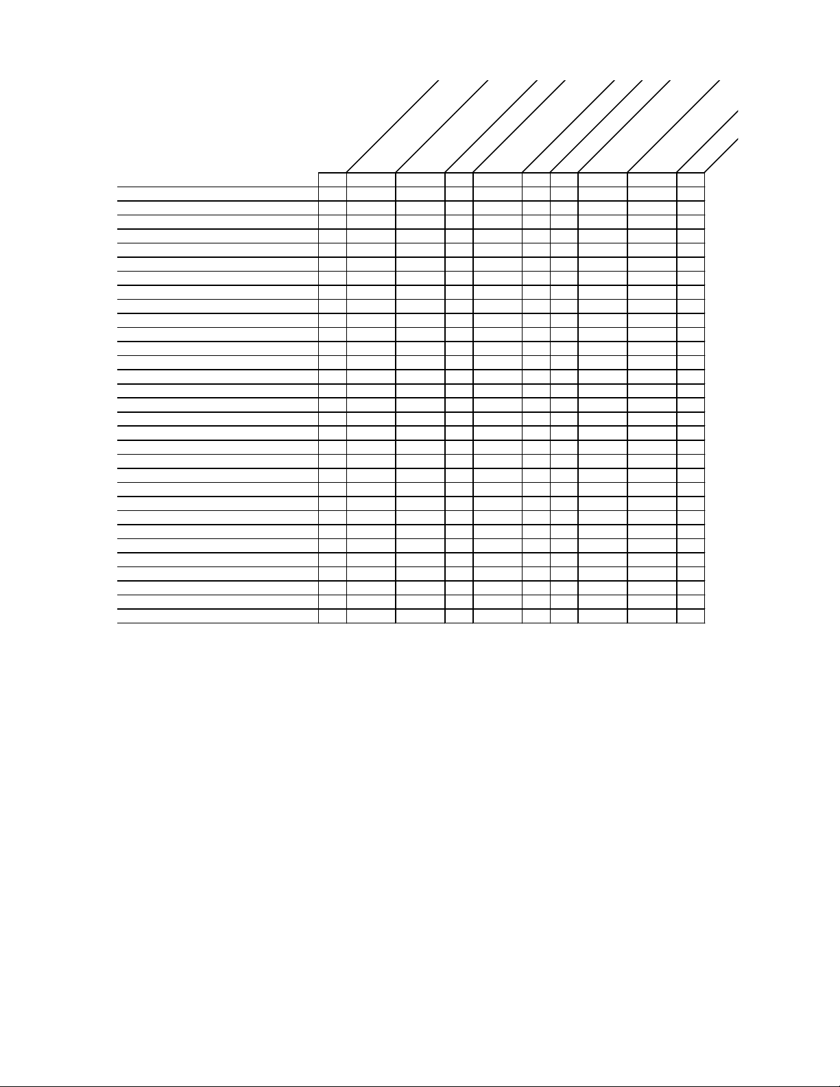
The following is an abbreviated guide of commonly encountered welding problems and their possible
causes, adapted from documents published by the Resistance Welder Manufacturers' Association and
reprinted with permission.
0428-INS-400 Rev. E
1-8
XXX
XXX
XXX
X
X
X
X
X
X
XXX
X
X
X
X
XXX
X
X
XXXXX
X
X
X
X
X
X
X
X
X
X
X
X
X
X
X
X
X
X
X
X
X
X
X
X
X
Weld Force Too High
Weld Current Too High
Weld Time Too Long
Weld Force Too Low
Weld Current Too Low
Weld Time Too Short
Electrode Face Too Small
Electrode Face Too Large
Insufficient Electrode Cooling
Electrode Allow Too Soft
Electrodes Not Flat & Parallel
Electrodes Misaligned
Poor Fit Up
Poor Heat Balance
Weld Spacing Too Close
Weld Too Close To Edge of Part
Dirty Material
Metallurgy of Material
Squeeze Time Too Short
Poor Follow-Up
No Speed Regulator On Cylinder
Poor Pressure Regulation
Hold Time Too Short
Transformer Tap Set To Off
No Weld Switch(es) In No Weld
Pressure Switch Open
Temperature Limit Switch Open
Electrodes Do Not Contact Work
Insulated Electrodes/Holders
Shunt Path In Secondary
Excess Ferrous Material In Throat
Emergency Stop Switch Open
* If Weld Force is too low, excess heating of the material surface may cause excess indentation.
ss
Exce
X
X
X
*
X
X
X
X
en
d
In
tro
c
Ele
Mushrooming
n
io
t
a
t
e
d
ersized
Und
N
u
We
gget
ld
Offset Weld
sh
Mis
ugget
N
We
t
apen
gge
u
N
Explusion at Surfa
ld
e
c
erf
t
n
t I
a
n
io
ls
u
cked o
ra
Exp
C
Nugget
XX
XX
X
XX
X
ace
r
Po
o
Di
X
X
X
X
X
r Wel
ol
sc
N
o
u
d
red
gge
ld
We
t
No Weld
Figure 1-3 Chart of weld defects and possible causes
Recommendations for Producing Quality Welds
To produce high quality welds consistently, follow these tips:
1. Be sure that the electrodes you are using are suitable for the job.
2. Use standard electrodes whenever possible.
3. Select an electrode tip diameter suited to the thickness of the stock being welded.
4. Make use of flow indicators for viewing and assuring proper cooling water flow through the
electrodes (typically, 1.5 gallons per minute).
5. Ensure that the internal water cooling tube of the holder projects into the tip water hole to within ¼
inch of the bottom of the tip hole.
6. Adjust the internal water-cooling tube of the holder to the appropriate height when switching to a
different length tip.
0428-INS-400 Rev. E 1-
9

7. Ensure that the top of the adjustable water-cooling tube in the holders is the proper height when
changing to a different tip length.
8. Coat the tip with a thin film of cup grease before placing it in the holder to simplify removal.
9. Use ejector type holders for easy tip removal that won't damage the tip walls.
10. Clean the tip taper and holder taper on a regular basis, removing any foreign materials.
11. Perform dressing of electrodes on a regular basis to maintain the correct contour.
12. Use a rubber mallet to align holder and tips, rather than a metallic tool.
Avoid these potential sources of weld problems:
1. Never weld using unidentified electrodes or electrode materials.
2. Avoid using special-purpose or offset tips if the job can be handled with a standard straight tip.
3. Do not use a small tip for welding heavy gauge materials or a large tip on small piece.
4. Do not overlook turning on the cooling water to the appropriate force when beginning to weld.
5. Never use a water hose that does not firmly fit the water connection nipples.
6. Avoid leaky, clogged or broken water connections.
7. Do not use holders that have leaking or deformed tapers.
8. Do not use electrode holders without an adjustable internal water cooling tube.
9. Avoid leaving the electrodes unused in tapered holder seats for long periods.
10. Do not use pipe wrenches or similar tools when removing electrodes.
11. Never dress an electrode using a coarse file.
These recommendations can help improve the quality and consistency of your welds. For more
information, you can contact the RWMA (Resistance Welding Manufacturing Alliance) or AWS
(American Welding Society) directly:
550 NW LeJeune Road
Miami, FL 33126
Tel: (800) 443-9353
Intl.: (305) 443-9353
URL: www.aws.org
0428-INS-400 Rev. E
1-10

Introduction to Resistance Weld Monitoring
Introduction
As discussed in the last chapter, what you see is not always what you get. Although a constant current
control may indicate that there is sufficient weld current to create a quality weld, unless the
measurement is taken at the electrodes, the actual amount of heat generated is only speculation. In
view of the fact that the generation of sufficient weld heat is a function of current density, it could
logically be argued that the primary cause of bad welds is inadequate current density. Many factors
affect current density: poorly maintained, worn or improperly sized electrodes, dirty materials, lack of
sufficient force at the tips and lack of sufficient weld current at the tips are just a few examples. This
being the case, how can a production person or weld engineer catch these (or other) potential problems
before they lead to bad welds? How do you make sure that what you see is what you get? The answer
lies in the subject of this chapter: resistance weld monitoring.
Why Monitor?
When Professor Elihu Thompson developed the concept of resistance welding, the idea of weld
monitoring most likely didn't exist. At that time, the only means available of differentiating a good
weld from a bad weld was through destructive testing. Even today, destructive testing is regularly used
to provide a reliable answer— 'good weld' or 'bad weld'— depending on how the weld reacts during its
destruction. For all its reliability, however, destructive testing doesn't tell the whole story. While it can
easily be determined whether a weld is good or bad, uncovering the precise factors that made it that
way is not as straightforward. Was there an excess or deficiency of one or many factors during the
weld? At what point or points in the welding process did the excess or deficiency occur? Resistance
weld monitoring can provide immediate answers to these questions.
With the advent of advanced computer technology, today's methods of observing and testing individual
weld integrity have advanced significantly, keeping in step with ever-evolving safety and quality
standards. By monitoring the welding process, compliance with international quality standards– such
as ISO and/or QS 9000+, or MVSS– is simplified. Weld quality can be instantly verified with
electronic documentation of individual weld characteristics; hard copy of weld data can even be
printed for comprehensive record keeping or for inspection. It's hard to dispute the integrity of a
product when the most critical stages in the manufacturing process have been systematically observed,
recorded and analyzed.
It's important to realize that weld monitoring is not a substitute for destructive testing. Rather,
monitoring and destructive testing go hand in hand. While destructive testing can unconditionally
guarantee whether an individual weld is good or bad, monitoring can show why that particular weld
was good or bad. Together, they can answer what is perhaps the most important question of all: is the
welding process consistently within the defined weld lobe?
0429-INS-400 Rev. C
2-1

Weld Lobes and the Weld Process
Each of the factors involved in the creation of a weld (Current, Voltage, Resistance, etc.) has a specific
range in which good welds can be made. This range is commonly known as the weld lobe. Bad welds
are made when the weld process falls outside of the lobe, so the simple answer to making consistently
good welds is to keep the process inside the lobe. It is not so simple, however, to ensure that this
happens for each weld made. This is where resistance weld monitoring is most valuable. The following
example uses a weld nut and the relative movement of the electrodes during the weld to examine what
goes on during the weld process. Livingston terminology (in italics) is used to describe various
measurements.
The nut itself has a number of little metal feet or projections on the bottom of it. These projections sit
on top of the workpiece to which they'll be welded. A measurement of the nut sitting on top of the
workpiece with the electrodes clamped on it before the weld is made is called the Initial Thickness.
When the proper electrode force is applied and weld current is fired, the projections melt into the
workpiece and create a weld. When the projections melt, the molten metal expands for a moment,
pushing the electrodes apart (this movement is called Expansion) before sinking down into the
workpiece (this movement is called Setdown). The expansion-setdown process is very much like a pot
of water boiling over before it's removed from the heat: as the metal is heated, it expands and then
quickly contracts as it cools to form the weld. A subsequent measurement of the nut/workpiece after
the weld is made is called the Final Thickness. All these different measurements of electrode
movement are measures of what's commonly called Electrode Displacement, or simply Displacement.
Measuring displacement provides a good indication of whether or not the resulting weld was formed
properly. If the nut sinks too far into the workpiece, it may be a sign of excessive heat which could
render the weld no good. It could also indicate that too much force was applied, the weld time was too
long, or a number of other things. Conversely, if the nut doesn't sink far enough, it may mean that not
enough heat was generated for the materials to weld properly, the force was insufficient, etc. Problems
with displacement can be problematic in many applications, such as welding hydraulic fittings. If the
setdown is too much/too little, chances are that the welded fitting will leak. When taken into account
that displacement is only one of many factors that, when measured, provide valuable information about
the formation of the weld and its overall quality, it becomes clear that weld monitoring is indeed a
valuable tool. Weld monitoring provides the user with an easy way to access a wealth of information
about the welding process— information that can actually help improve the process itself, as well as
alert the user to any number of potential problems.
Styles of Monitoring
There are many different types of monitoring systems on the market nowadays. These systems can be
broadly categorized into three different styles, which for educational purposes are nicknamed as
follows: Before & After monitoring, Mass monitoring, and Dynamic monitoring.
Before & After Monitoring
As the name suggests, Before & After monitoring (hereafter referred to as BA monitoring) focuses on
only two phases of the weld process: before the weld is made, and after the weld is made. This type of
monitoring is typically used to measure displacement only. As mentioned above, measuring
2 0429-INS-400 Rev. C
2-2

displacement can indicate whether the resulting weld was formed properly. BA monitoring measures
the displacement before the weld is made (Initial Thickness), and then again after the weld is made
(Final Thickness). However, if it is determined that the displacement is consistently below where it
should be (e.g., the nut is not sinking far down enough into the workpiece to make a good weld), BA
monitoring cannot identify exactly where in the process the problem is occurring. Similarly, the BA
monitor may indicate a normal setdown, yet the nut may be sinking down much too quickly due to
expulsion. While BA monitoring provides an account of the beginning and end of the weld process, the
key middle-portion of the process is unwisely overlooked.
Mass Monitoring
Mass monitoring provides a more in-depth examination of the weld process, but does it by averaging
all the measured parameters during the course of the weld. Using the weld nut from the displacement
example in the previous section, we'll examine force during the weld process. The nut and workpiece
are clamped together under pressure between the electrodes, and the weld current is fired, generating
heat and creating a weld. A Mass monitor will measure parameters during the weld process and will
provide an average for each after the weld is made. In this particular example, the monitor might
indicate that the average force during the weld was 800 lbs. Suppose, however, that subsequent
destructive testing of the part showed that the weld was bad. Why would this be the case if the monitor
indicated that the average force was appropriate?
The trouble with this type of monitoring system lies in the averaging of the parameters before a result
is presented. Recall that a typical weld cycle can be broken up into three separate sections: the preweld, weld, and post-weld segments. If the force during each of these sections was 1700, 300, and 400
lbs., respectively, the average would be 800 lbs. The end result appears acceptable, but the averaging
only serves to disguise substantial irregularities in the force during the weld process. Mass monitoring
is also relatively insensitive to changes in the weld schedule and weld current. Aspects such as
upslope and downslope are recorded, but are delivered as averages rather than by the cycle (or
halfcycle). Although the average current for a 10-cycle weld could be the same as for a 20-cycle weld,
there would probably be a great deal of expulsion in the 20-cycle weld. A Mass monitor would not be
able to detect anything amiss in this situation, because the average would likely be an acceptable
figure. While Mass monitoring is a more thorough method of observation than BA monitoring, it's still
not the most effective method of monitoring the resistance weld process.
Dynamic Monitoring
Dynamic monitoring is currently the most comprehensive method of observing and recording the weld
process. A Dynamic resistance weld monitor measures weld parameters in real-time, while the weld
process is happening. More detailed than a before/after picture, and more accurate than an average of
each parameter, a Dynamic monitor provides a complete view of the weld process as the weld is being
made, measured in either halfcycles or cycles (based on a 50 or 60 Hz sine wave). Because the weld
process is observed so closely, events such as Expansion and Setdown can be pinpointed down to the
halfcycle. If weld irregularities are suspected, recorded weld data can be analyzed to determine where
in the process they're occurring and what factors are contributing to the problem. Potential problems
can also be detected before they occur: parameters such as resistance or force can be trended to
ultimately predict electrode wear and improve preventive maintenance schedules.
0429-INS-400 Rev. C
2-3

Effects of Different Factors
Each of the four main parameters— Current, Voltage, Force, and Displacement— affect the properties
of a weld.
Current, measured in KA, is typically set and expressed as a percentage of heat on weld controls used
by a number of manufacturers, although some of the more modern equipment allows a current setting
in KA instead of a percentage. Throughout the industry, the majority of welds are performed using
single-phase AC current, but there are other sources of welding current used as well. These include:
• Single and Three-phase rectified DC
• Mid-frequency DC (600-1,200 Hz)
• High-frequency DC (2,000-25,000 Hz)
• Capacitive Discharge DC
Whatever type of current is used, control of current density during welding is the most important factor
involved in making a quality weld. Without proper current density, too much heat can be generated,
leading to expulsion and/or part deformation. Conversely, there may be too little heat generated,
causing cold welds and/or incomplete weld nugget formation. Some people uphold the 'bake it longer'
theory, which prescribes lower weld heat for a longer time. While this reduces expulsion, the longer
weld time makes it much less efficient. Others think that in order to have good welds, expulsion is
necessary as an indicator that a weld is being made. However, tiny pieces of molten metal exploding
out of a weld cause the weld itself to be weaker than it would be without expulsion.
Voltage, measured in Volts, is also a key indicator during the weld process. As discussed earlier,
voltage is a relative measure in that the location of the measurement is important. The voltage in the
secondary of a welder can vary during operation due to a variety of factors, including:
• variances in the part fit-up;
• loose connections;
• line load variations within the plant;
• differences in power factor throughout the day.
Voltage variations at the tips due to worn or pitted electrodes, dirty materials, or insufficient surface
contact with the workpiece can also affect resistance and current density. As a partial solution, many of
today's controllers are equipped with an Automatic Voltage Compensation (AVC). If a voltage drop in
the factory line is detected, the control will adjust in an attempt to provide the same amount of energy
to the weld. Despite the adjustment, what comes out of the transformer is not necessarily what comes
out of the electrodes. The same conditions apply to constant current controls. Even though the amount
of current coming out of the transformer secondary is regulated, the amount at the tips may be variable.
Force, measured in pounds per square inch (psi), pounds (lbs.), or kilograms (kg), indicates the amount
of pressure being applied to the electrodes before, during and after the weld process. Electrode force is
typically provided by air, hydraulic, or spring pressure. Changes in force can result in a significant
increase or decrease in resistance as the weld is taking place. This is particularly true of welders using
2 0429-INS-400 Rev. C
2-4

air over oil cylinders. If the electrode force drops too low, resistance can increase between the
electrodes and the workpiece, resulting in expulsion. If the electrode force becomes too great, the
resistance is lowered, resulting in poorly formed nuggets or even brittle welds, particularly with coated
metals. Excessive force also reduces electrode life, causing tips to mushroom more quickly.
Electrode displacement, measured in inches or millimeters, indicates the relative movement of the
electrodes during the welding process. The displacement measurement corresponds with the nugget
formation at the weld site: as the materials being welded become molten, the metal expands, pushing
up against the electrodes. Force is maintained as the electrodes push back, applying pressure to the
weld. Follow-up force is critical in containing nugget expansion and in eliminating weld expulsion.
How Monitors Work
Typically, a weld monitor receives input from the welder through a variety of sensors that can be
configured for specific applications. These sensors measure the characteristics of the weld process and
transmit this data to the weld monitor. Toroids are used for measuring current, and pressure sensors or
load cells are used for measuring force. Relative movement of the electrodes during welding is
measured using displacement sensors, while voltage leads measure voltage at the weld head. Data is
collected from all or a combination of these sensors and displayed by the halfcycle, cycle or average
for the entire weld, depending on the type of monitor used. The more weld parameters monitored, the
harder it is to unknowingly make a bad weld. Using a Dynamic monitor, factors that may adversely
affect the quality of a weld can be easily tracked and identified, and the exact moment when a problem
occurs can be isolated, down to the halfcycle.
A weld monitor will not control the weld process, nor will it inform the user what the process
parameters are supposed to be. It will confirm if welds are made within the limits set by the user, and a
monitor can be used to simplify methods of refining process parameters. It's important to understand
that the user first needs to define the weld lobe and proper weld schedule. Once a weld lobe and
schedule are established (according to internal standards, or through trial-and-error), monitoring can
begin.
More Benefits
Below are additional benefits of weld monitoring:
• Optimize weld schedules for individual parts and conditions.
• Ensure a 100% inspection level— every single part being produced can be monitored in
seconds and the resulting weld data compared to known good values.
• Detect weld setup problems and maintenance issues before they cause bad welds.
• Provide traceability of welded components— the recorded hard copy or electronically stored
weld history helps ensure regulatory compliance in specialized industries.
• Minimize production downtime— if a welder isn't working properly, the problem can quickly
be tracked down and repaired faster. Less downtime means more money!
0429-INS-400 Rev. C
2-5

Both quality improvements and efficiency can be gained through weld-process monitoring. For
example, by demonstrating and tracking the consistent high quality of primary welds, the need for
additional "safety" or "delta" welds can be reduced or even eliminated. The ability to quantify what
constitutes a known good weld makes it possible to achieve consistent results, even in high-volume
situations. Productivity gains can also be achieved by replicating and tracking those conditions that
have been shown to result in ideal welds. In a high-volume, automated factory line environment, the
resulting gain in productivity can be substantial.
2 0429-INS-400 Rev. C
2-6

Tolerancing and Monitoring
Introduction
This chapter will introduce Livingston's concept of dynamic resistance weld monitoring. The
definitions of tolerances and segments as they pertain to a WeldWise™ 2400 will be discussed, as well
as how these features allow the user to immediately identify and correct faulty parameters or
conditions that can produce poor quality welds. Different parameters that can be monitored using
Livingston equipment will be identified, in addition to some of the ways that monitoring can be used to
simplify and refine the weld process.
Livingston WeldWise™ Monitor
The WeldWise
connected to the appropriate sensors, can be used to monitor a single weld head in a fixed location or
rotated on your factory floor to monitor different weld heads, one at a time. If a weld is not within
master tolerance limits, the WeldWise 2400™ sends a reject signal to a PLC or similar controller,
which is then displayed on the monitor as a 'rejected' weld. If the weld is within tolerances, the
WeldWise 2400™ sends an accept signal, which is displayed as an 'accepted' weld.
The WeldWise™ 2400 performs real-time monitoring on a halfcycle-by-halfcycle basis for AC welds.
A 'halfcycle' is exactly what the name implies: one half of a weld cycle, based on a 50 or 60 Hz sine
wave.
Signatures and Masters
Once a Livingston weld monitor and sensors have been installed and the WMS (Weld Monitoring
Software) program is running, the monitor continually collects data from the sensors. When a weld is
made, information about that weld is captured, analyzed, displayed and stored by the monitor. This
information is called a weld signature. Simply put, a weld signature is the distinct characteristics of
any particular weld. From either one or a collection of high-quality weld signatures, a master signature
is made. Throughout this text, a master signature and its related tolerances (see below) will be referred
to simply as a master. A 'high-quality' weld signature is the signature of any production weld made that
was proven to be high quality through destructive testing. A master is a set of values representing those
conditions that make for a high-quality weld.
A master is created in the WMS program by making a high-quality production weld and using its
corresponding signature. The master is what defines the acceptable range for individual weld
parameters through tolerances, which are initially drawn from a set of default values installed when the
master is made. Once a master is created, tolerances can be individually modified by the user and
depending on the application, can be loosely or strictly defined. Once tolerances are defined for a
master, every subsequent weld made will be compared with the stored master tolerance limits. If the
weld does not fall within the master tolerance limits of that master, the monitor will record a reject
signal and display it as a rejected weld. Using a PLC, this signal can also be set to trigger a variety of
rejected-weld responses, such as lights, buzzers, and reset-reliant restrictions (the electrodes will
™
2400 Dynamic Resistance Weld Monitor is a portable bench top unit that, when
0430-INS-400 Rev. D 3-
1
remain clamped until the ladder logic has been reset). Parts with rejected welds can then be
immediately identified and isolated from parts with accepted welds.
Selecting a Master
A Livingston weld monitor can store a number of masters (contains master tolerance limits) that are
selectable using the binary select inputs. Selecting different masters is desirable for weld heads that
make more than one weld perhaps with a different weld schedule or different part stack up. Please refer
to the General Setup Menu section in this manual for more information on binary select modes. The
WeldWise 2400 Binary Select inputs are 24V discrete connections located on the rear of the monitor.
Tolerances
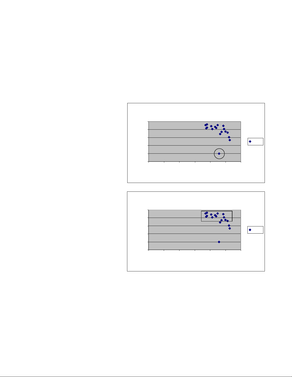
Weld Data : Curre nt vs. Force
Understanding tolerances requires an
understanding of the weld lobe. Restated
simply, a weld lobe is the range for any
welding parameter in which a highquality weld can be made. A weld lobe
is typically defined by destructively
testing welds and then examining the
corresponding weld data to determine
quality limits.
915
910
905
900
Force in Lbs.
895
890
024 681012
Current Rms in KA
force
An example of collected weld data is
shown in figure 3-1. In this graph, the
diamond shapes represent welds made.
Figure 3-1 Weld data showing Force and Current
Example of a We ld Lobe
The horizontal axis is the weld Current
(measured in KA) and the vertical axis
is Force (measured in lbs.). Although
915
910
this particular graph only shows force
and current, all weld parameters can be
toleranced using a Livingston monitor.
The locations of the diamonds show
exactly how much force was used at a
particular current for the displayed weld
set. For example, the circled diamond in
905
900
Force in Lbs.
895
890
024 681012
Current Rms in KA
force
figure 3-1 indicates a weld made with
approximately 9.5 KA of weld current at
Figure 3-2 Example of a Weld Lobe for Force
895 lbs. of force.
To determine the lobe for this particular data set, each part associated with these welds would be
destructively tested. Suppose that testing revealed that the welds made within a range of about 908 to
914 lbs. of force, with a range of about 7 – 11 KA of current were all good. If a box is drawn to isolate
these ranges, as shown in figure 3-2, the area within that box is the weld lobe. The box itself represents
the tolerance limits, or the limits of the range in which good (high-quality) welds can be made. A
master is what provides the monitor with a weld signature that is within the weld lobe. Tolerances are
what define the boundaries of that box. Once a master is created and toleranced, Livingston monitors
will reject any welds that have fallen outside of the box (out of tolerance), while any welds inside the
box (within tolerance) will be accepted.
0430-INS-400 Rev. D
3-2

Every factor involved in making a weld has its own weld lobe and set of unique tolerances. There are
multiple parameters that can be measured and toleranced using a Livingston monitor. The WMS
program makes it easy to define, track and record tolerances for each parameter critical to the weld
process. For maximum flexibility, acceptable tolerances can be specified by absolute or relative values
when comparing weld data in real-time against a master.
Measured Parameters
Livingston monitors capture measurements from up to four sensors attached to a welder. From these
four measurements, the monitors then calculate and record the following parameters:
• Current Rms • Part Expansion
• Current Peak • Electrode Setdown
• Voltage Rms • Conduction Angle
• Voltage Peak • Energy
• Force • Resistance (Dynamic)
• Initial Part Thickness • Number of Halfcycles
• Final Part Thickness
For a complete definition of each of these measured parameters, please refer to section 6, the WMS
Reference Guide.
Segments
Since there are many different weld processes, users may be more interested in observing and
analyzing certain time periods during a weld. To accommodate these differences and needs, Livingston
devised the concept of segments. A segment is simply a collection of halfcycles before, during and
after the firing of weld current. By default, there are three segments created when a master is made: the
Pre-Weld (Squeeze), Weld, and Post-Weld (Hold) segments. Different tolerances can be set for each
segment, segment lengths can be increased or decreased and new segments can easily be created.
Using segments, each weld can be divided into as many parts as necessary to focus on the data that is
critical to the weld process. Consider the following example:
Coated steel is being welded with the following weld schedule: 8 cycles of Squeeze, 10 cycles of Weld
and 12 cycles of Hold. The objective is to monitor the current density during the Weld time, to ensure
sufficient concentration for high-quality welds. According to the factory weld lobe, the current at the
electrodes during the weld must be 12 KA, with an allowable difference of only +/-0.5 Amp. After
examining preliminary weld data, it is discovered that the current during the first few halfcycles of the
Weld period is much less than 12 KA. The reason for the decrease is that the coating must first be
burned off before the weld current actually reaches the steel at the faying surfaces and makes the weld.
How can tolerances be properly set to accommodate the weld lobe specification of 12 KA +/- 0.5 Amp
without automatically rejecting welds during the time it takes for the coating to burn off?
0430-INS-400 Rev. D 3-
3

To resolve this issue, the exact time (in halfcycles) needed for the weld current to burn through the
coating could be determined by examining collected weld data. Using this information, a segment
could then be added that would effectively divide the Weld segment into two. The first Weld segment
would start when the weld current fires, and would end when the coating had been burned off. The
weld current tolerances in this particular segment could be widened to accommodate the change in
current density when burning through the coating. The second Weld segment would begin at that point
when the weld current had reached the metal to be welded, and would end when the weld current
ceases. In this segment, the weld current tolerances could be tightened to ensure the necessary amount
of current (in the example, 12 KA, +/- 0.5 amps) to make a good weld.
Segments provide a useful means for organizing the weld data and comparing changes over time. The
ability to specify different tolerances within several different segments allows the user to precisely
isolate weld factors that may be critically important to weld integrity and include these factors when
accepting or rejecting welds.
Data Collection
Data can be collected for each halfcycle, segment and/or weld. Please refer to the General Setup
Menu in section 6, WMS Reference Guide.
Weld data is continuously recorded whenever the weld monitor is operating, however only a prespecified amount of data is stored. The monitor is 'triggered' at the instant that weld current is fired;
this moment is referred to as the trigger. The quantity of data stored is based on the trigger. The user
can choose a number of halfcycles prior to the trigger (the Pre-weld segment) and a number of
halfcycles after the current has ceased (the Post-weld segment), depending on the importance of this
data to weld analysis.
For example, a weld schedule may have 8 cycles (16 halfcycles) of Squeeze, 12 cycles (24 halfcycles)
of Weld and 8 cycles (16 halfcycles) of Hold. In this particular process, the force during the last six
halfcycles of the Squeeze period and the first eight halfcycles of the Hold are especially important.
Accordingly, the segment length can be set to include only those specific halfcycles. All additional
data before and after the indicated number of halfcycles would consequently be discarded by the
monitor.
0430-INS-400 Rev. D
3-4
Getting Familiar With The
WeldWise™ 2400
This chapter will review the external features of the WeldWise™ 2400 (hereafter referred to as 2400),
as well as the various menus and options of the Weld Monitoring Software (WMS) program, including
the proper shutdown procedure for all Livingston equipment.
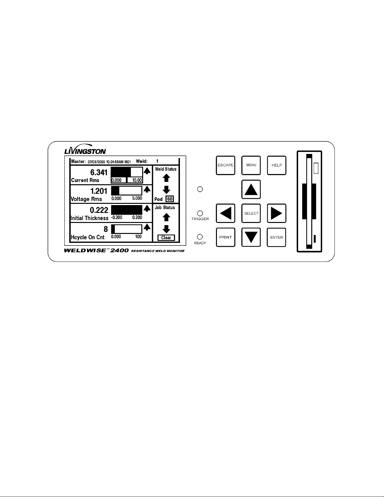
The WeldWise™ 2400 Front Panel
Figure 4-1 Front panel of the WeldWise™ 2400
The WMS program can be fully controlled from the front panel touch-pad and touch-screen of a
Livingston weld monitor without requiring an external keyboard, video monitor or mouse. The touchpad refers to the cluster of arrow and control keys on the right hand front panel. These keys allow the
user to scroll through menus, screens and fields in the program, making selections and performing
tasks. The touch-screen refers to the touch sensitive display. The touch-screen itself is interactive: by
pressing an item on the display, the user can select or move it and navigate through menus.
Depending on the equipment setup and available space, it may be convenient to use a keyboard, video
monitor and/or mouse. Although there are several different methods for performing each command and
executing various tasks in the WMS program, there are certain functions, such as renaming masters,
which are only possible using a keyboard. However, these functions are optional and have no effect on
the quality of weld monitoring. Use of a video monitor and mouse is optional.
A floppy disk drive is located on the front of a 2400. This drive is used to copy certain settings onto a
floppy disk for later use or to install software upgrades.
0431-INS-400 Rev. D
4-1
WMS Navigation and Editing
There are two modes in the WMS program: navigating mode and editing mode. Navigating mode
simply refers to moving from one portion of the screen to another or from screen to screen. Editing
mode refers to selecting an item for change and/or actually changing the value of it.
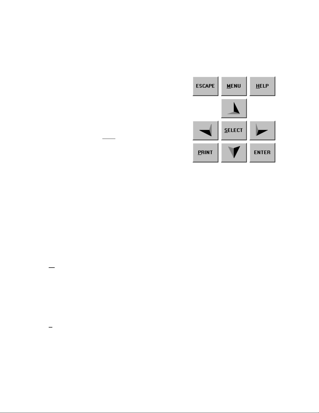
There are four directional arrows on the keypad. In the
middle of the arrow is a SELECT button, and an ENTER
button on the bottom right. On the top are three other
buttons: ESCAPE, MENU and HELP. The PRINT button is
on the bottom left.
If you are using an external keyboard, these options may be
quickly accessed with the 'hot keys', represented by the
underlined letters (ALT + letter). You can also use the
keyboard arrows instead of the arrows on the touch-pad.
Navigation
Generally, anytime you move within a screen or from screen to screen, the location of the
cursor is shown by a highlighted or enhanced border.
ESCAPE This button reverses your path through the program. For example, if you selected
ENU This button accesses the Main Menu from many, but not all, points in the program.
M
Arrow Use the arrow buttons to move up, down, left or right on the touch-screen. The
Editing
SELECT The SELECT button is used to select an item. This either performs the action
Figure 4-2Keypad buttons
the Data option from the Main Menu, you can use the ESCAPE button to return to
the Main Menu. ESCAPE always takes you back one level at a time towards the
Main Menu of the program or cancels your previous action. If you press ESCAPE
enough times from anywhere in the program, you will always end up at the opening
program screen.
Use it to return to the Main Menu options.
arrows will also allow you to change options once an item has been selected.
associated with that item, or puts you into Editing mode. A selected item is usually
highlighted, shown with a highlighted border or indicated with a flashing cursor.
Once an item has been chosen (shown by a highlighted or enhanced border) in the
touch-screen, press the SELECT button to highlight (shown by a different fill color)
that item for use or change. For example, if the item is a menu option, the program
opens to the next appropriate display. If the item is parameter, you can cycle
through a list of additional choices using the Arrow Buttons. If the choices show a
0431-INS-400 Rev. D
4-2
 Loading...