

Page 1
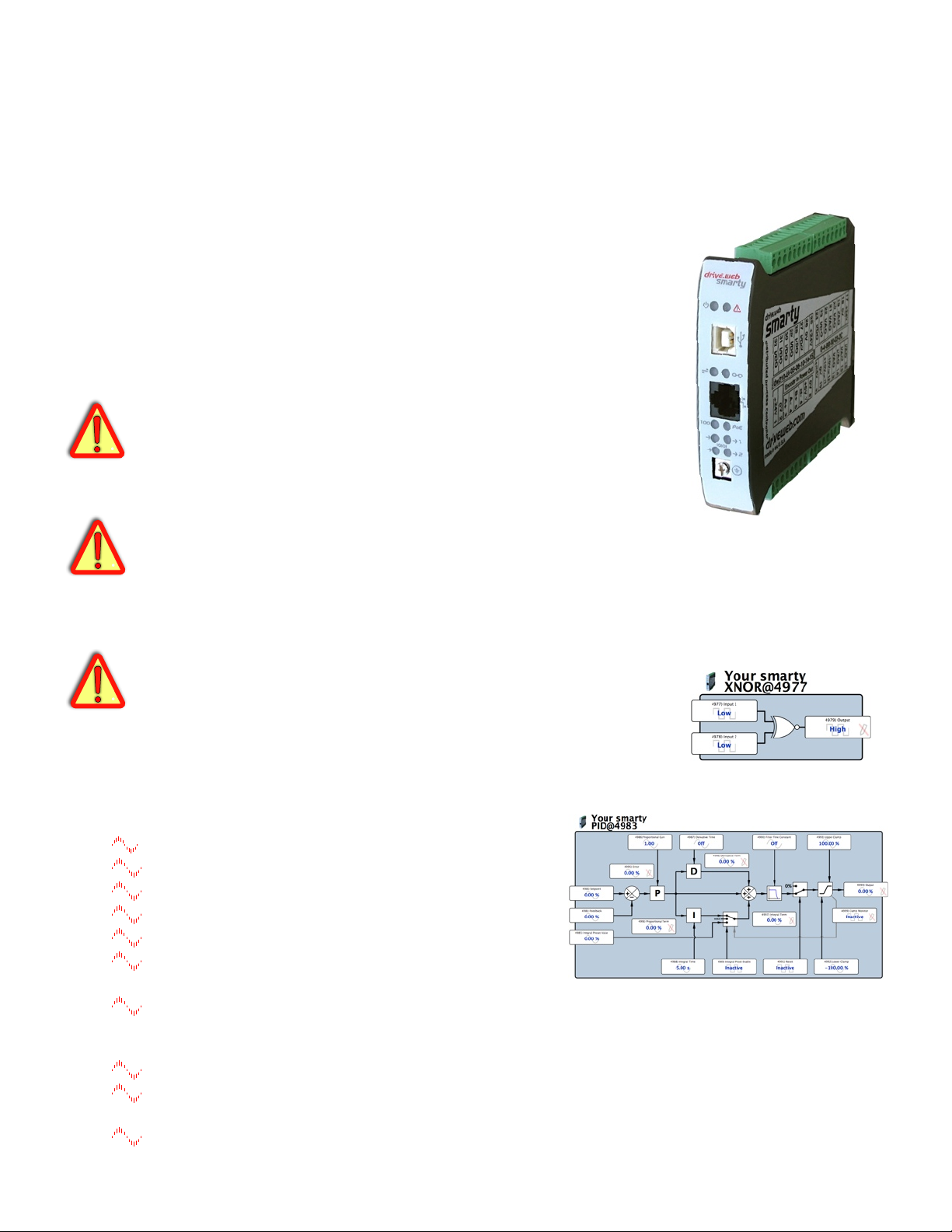
drive.web
smarty
dw210 - Installation &
Operation Manual
Contents!! ! ! ! ! Page
Warnings, Introduction, Features! ! 1
smarty Options ! ! ! ! ! 2
Winder specials, Physical Installation! ! 3
Ethernet, savvy Intro & Upgrades! ! 3-5
smarty Terminals!! ! ! ! 5
Option 03 - Analog & Logic I/O! ! ! 5,6
Options 07, 08 & 11 Encoder Inputs & Control!7
Appendices - Function Blocks, Products!! 8
Warning!
It is essential that you read and understand this entire manual and the entire
contents of the savvy software “Help” menu before proceeding with your
installation and product configuration. For more information and to download
product manuals and software, go to www.driveweb.com.
Warning!
Your use of savvy software and drive.web devices may cause motors and
machinery to power up with high voltages or start or operate in an unexpected,
dangerous or lethal way. It is essential that you are completely familiar with savvy
and all of the equipment and the system design you are working with before
attempting to program or edit a program or connect to any live device.
Warning!
You are entirely responsible for the configuration or use of any drive.web
product. By configuring or using these products you agree to indemnify and hold
harmless Bardac Corporation, its’ employees, directors, officers, distributors and
resellers against the consequences of your configuration or use of the products.
smarty Features
drive.web distributed process control over Ethernet
Modbus TCP/IP over Ethernet with option 04.
Internet accessible configuration, monitoring & control.
“Drag ‘n drop,” connections, graphical documentation.
Automated, on-line upgrades with savvy software.
System libraries Basic and optional; Process Control,
Winders, Math & Encoder Control.
Available Function Blocks; Arithmetic, logic, advanced PID, comparator,
filter, latch, timer, profiler, counter, drive control, ramps, diameter
calculator, taper tension, torque compensator for winders and more.
Configurable Discrete I/O; 8 Digital Input/Outputs, 8 Analog Input/Outputs
Optional I/O; Direct Encoder, Dedicated Encoder Module, Dual ModbusRTU,
CAN bus, High Voltage I/O.
Power over Ethernet Option Power your smarty with PoE technology.
smarty HG502055 v. 5.1! ! www.driveweb.com ! ! ! ! Page 1/8
Page 2
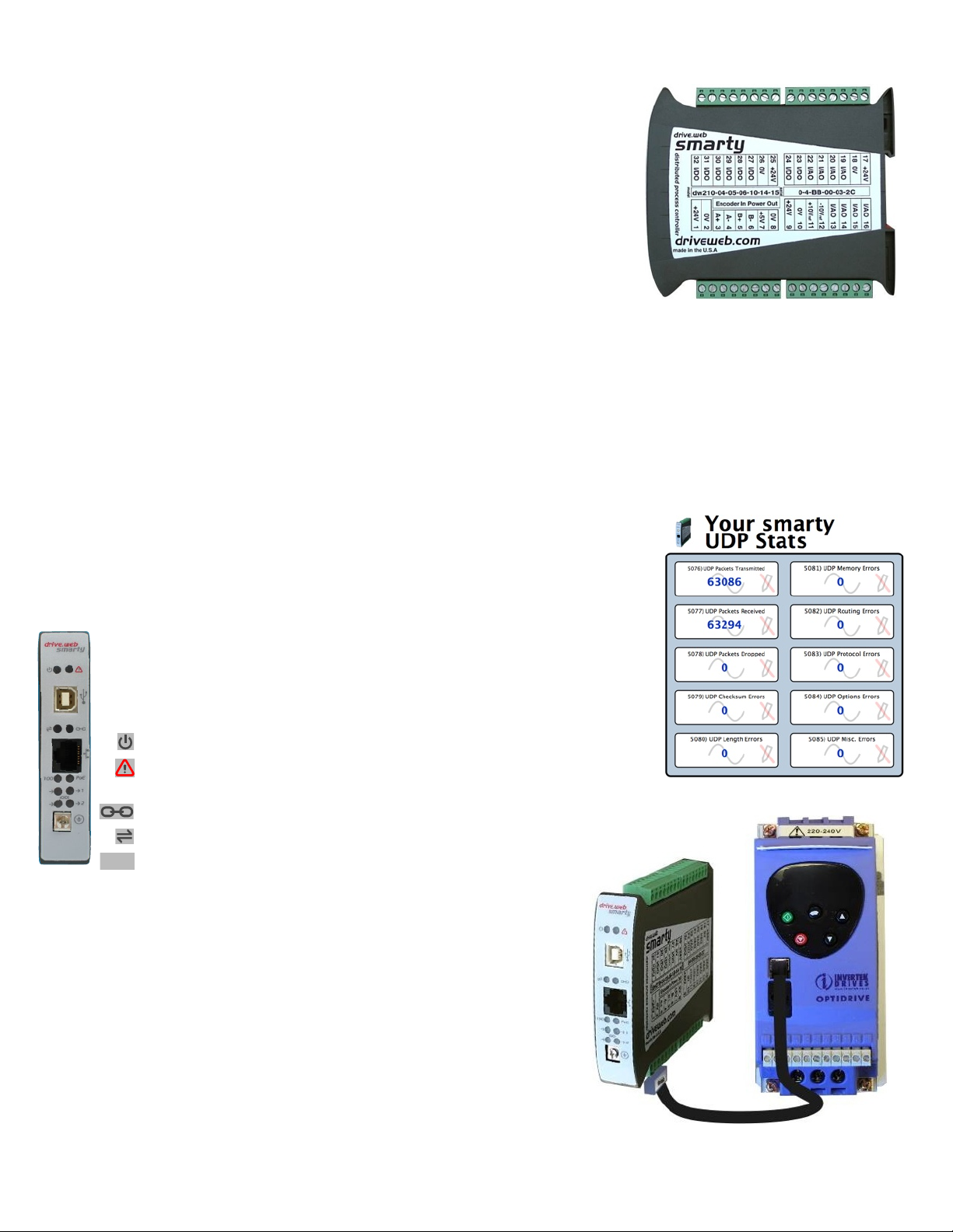
smarty base models include:
99.00mm Ref.
drive.web
smarty
PoE
smarty
smarty
drive.web 10/100Base-T(X) Ethernet enabled distributed process control.
Standard I/O Package details on page 6. 16 configurable terminals.
8 Analog Input/Outputs and 8 Digital Input/Outputs. Analog
Inputs continue to be available in Output mode.
Analog Inputs ±10V, 100kΩ input impedance, 16 bit
resolution. ±25V maximum.
Analog Outputs 0 to ±10V, 10mA max. 16 bit res. ±11V max.
Digital Inputs 5, 12 or 24V Logic Inputs.
Digital Outputs 24V, 50mA max, source and/or sink selectable.
Sink mode may require fusing, see page 6.
+10V and -10V references provided, 20mA max source.
Four +24V and Four 0V terminals for power and control reference.
Basic Control Function Block Library with arithmetic, logic, PI,
clamps and more. See Appendix A for function block listing.
New Network Stats Block - in-depth network troubleshooting.
Complete logging of TCP, UDP, network, data link hardware
and software errors and packets dropped:
Real Time Clock with calendar, time stamp, rechargeable battery.
Chassis Ground (Earth) Definite grounding for ease and security. Do
Indicator LEDs in front panel. For setup, trouble shooting and monitoring:
smarty models:
dw210- smarty Standard Distributed Process Controller.
dw213- smarty-o for Optidrive Plus AC Sensorless Vector
dw215- smarty-yf7 for Yaskawa F7 Vector Drives. Standard
smarty HG502055 v. 5.1! ! www.driveweb.com ! ! ! ! Page 2/8
NOT use for 0V control wiring.
Power On Green LED
Fault Red LED, alarm requiring immediate action. Check power supply,
connect with savvy or contact drive.web for more information.
Ethernet Link Green LED indicates current Ethernet connection.
Ethernet Activity Yellow LED indicates data transmitted or received.
100BaseTX Green LED connection with a 100Base-TX device.
Drives. Standard smarty features plus serial data link and
comprehensive drive parameter control function blocks.
Use dw213 Manual, HG502172.
smarty features plus dedicated serial data link and
comprehensive drive parameter control function blocks.
Use dw215 Manual, HG502253
Page 3
smarty Options
Winder smarty
Taper Tension@5113
diameter
min. diameter
5113) Diameter Calculator
Diameter Calculator@5054
5114) Tension Setpoint
0.00 %
5116) Taper Strength
0.00 %
5117) Tapered Tension
0.00 %
5115) Taper Type
Linear Taper
5118) Trim
0.00 %
5119) Output
0.00 %
Option
Port 1
Port2
17
Not Used
Isolated ModbusRTU Slave
18
Isolated ModbusRTU Slave
Encoder Comms
19
Isolated ModbusRTU Slave
ModbusRTU Master
20
Not Used
ModbusRTU Master
21
Not Used
Isolated ModbusRTU Master
22
ModbusRTU Master
Encoder Comms
23
Isolated Modbus Master
Encoder Comms
smarty
1
2
PoE
lOlOl
Label Type 875
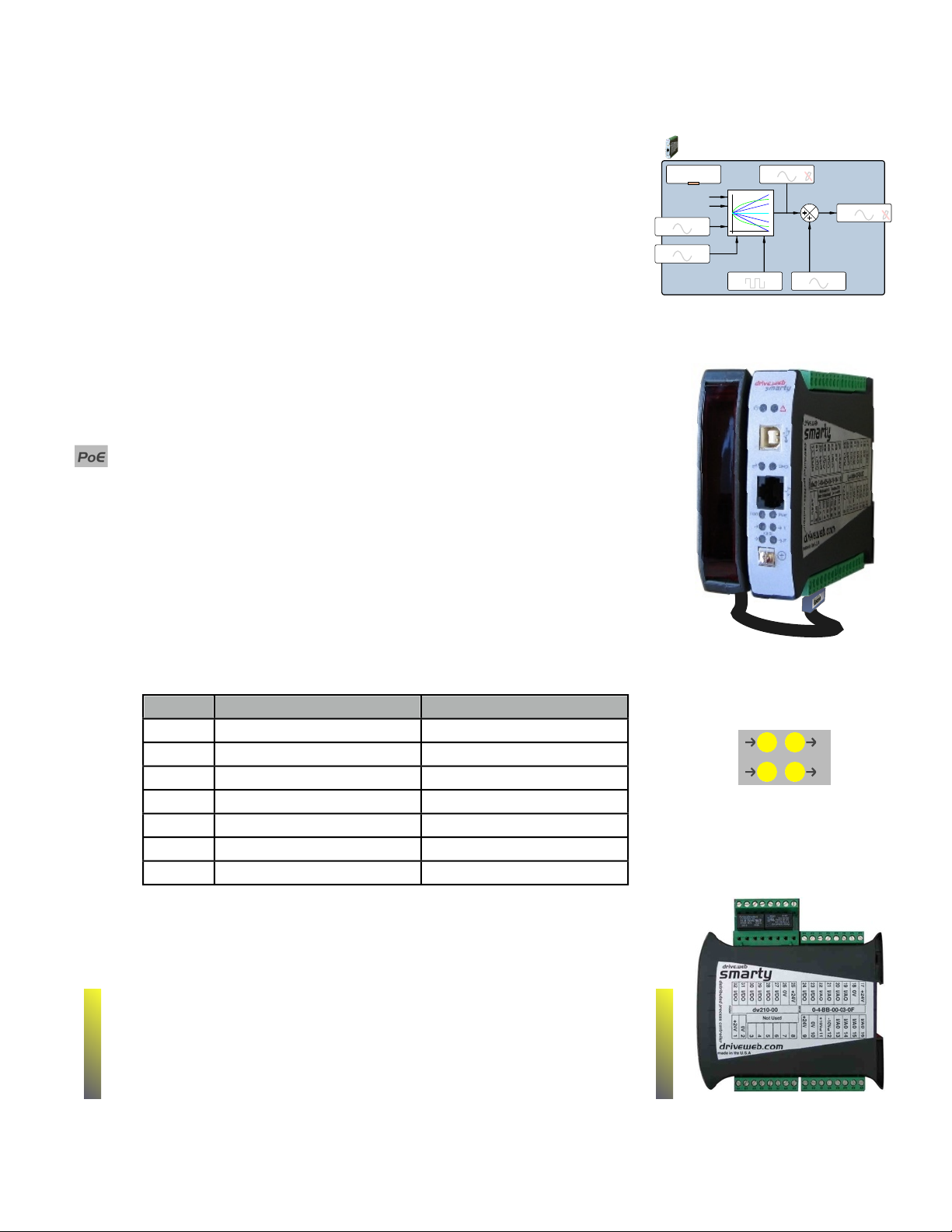
04 ModbusTCP/IP. Ethernet enabled Modbus slave/server.
05 Process Control. Function Block Library 1 - Math, Logic, PID,
Switches, Comparators, User data log, Profiler, Presets, Latch, Filters,
Counters, Timers and more, see Appendix A.
06 Winder Control Function Block Library 2 - Diameter Calculator,
Taper Tension, Torque Compensator.
10 Advanced Math Function Block Library 3 - Trig, Polynomials, Log,
Exponent, more, see Appendix A.
11 Encoder Control Function Block Library 4 (Requires smarty
Encoder Input Module with dual encoder option, dw230-02 or -03).
Speed Lock, Registration, Position Function Blocks.
14 Power over Ethernet IEEE 802.3af PoE Technology. Freedom
from other power supply requirements. Green LED indicator.
15 Direct Encoder Receiver Bi-directional incremental with marker, EIA
422/485, up to 300kHz, 24V. Encoder logic and speed function blocks.
16 External Encoder Interface Port Two-wire comms connects to the
smarty Encoder Input Module, dw230, up to 500 ft away. dw230 options
include dual encoders with event inputs and single or dual EIA422 retransmit.
17 Through 23 smarty Serial Ports ModbusRTU uses EIA485 at
230.4Kbps max. Isolated option provides 250V isolation for large systems.
Four yellow LED indicators - data received and transmitted on Port 1 and 2.
24 High Voltage Digital I/O Isolator 2 NO Contacts, 4 120VAC inputs. See page 7.
smarty Options Important Notes:
Modbus Options 04 and 17 through 23 enable communication with a
wide range of industrial devices from drives to operator stations, PLCs
! !
SCADA systems. It is essential that you read and understand the entire drive.web Modbus Installation and Operation Manual, HG502421,
included with these options before using them.
Options 04, 05, 06, 10 and 11 are software options, easily field installed
Options 16 through 23 are not available with -15, Direct Encoder Receiver.
smarty HG502055 v. 5.1! ! www.driveweb.com ! ! ! ! Page 3/8
Serial Port LEDs
Receive Transmit
Page 4
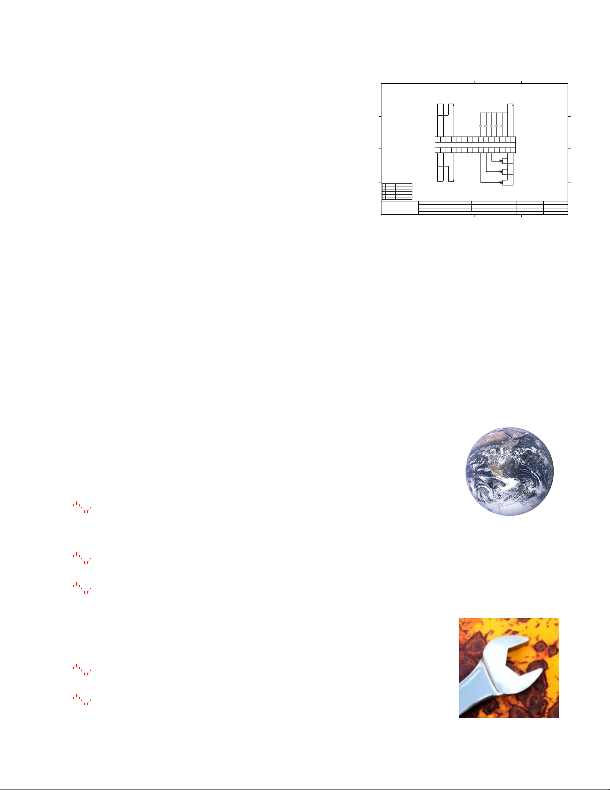
smarty Specials
OPEN LOOP WINDER
CIRCUIT DIAGRAM
1
ISS DATE APPROVED
A 12 JAN 07 T. COURNOW
B 26 JAN 07 T. COURNOW
C 07 FEB 07 T. COURNOW
DEVICE:
OPTIONS:
MODEL:
SPECIAL MODIFICATIONS:SMARTY
AVAILABLE -02, -04, -07, -08, -09, -10
DW110-1101
NONE
SM1
0VDC
SUPPLY
COM
+24VDC
SUPPLY
EXTERNAL
DIAMETER
D5
D7
DIAMETER
HOLD
C2
SPEED
DEMAND
C3
TORQUE
DEMAND
0V
COM
D8
WEB
SPEED
D1
REEL
SPEED
D2
TENSION
SETPOINT
D3
TAPER
SETPOINT
D4
0V
COM
C8
+10 VDC
REF
C1
C7
LOAD
DIAMETER
C6
TENSION
ENABLE
C5
STARTD6JOG
LOADJOG STRT TENS HLD
24 VDC
SUPPLY
BY OTHER
+
-
C4
0V
COM
TORQUE
DEMAND
(0-10 VDC)
+
SPEED
DEMAND
(0-10 VDC)
+
P3
DIAMETER
10K,1T
P2
TAPER SP
10K,1T
P1
TENSION SP
10K,1T
REEL
SPEED
(0-10 VDC)
- +
WEB
SPEED
(0-10 VDC)
- +
1 2 3 4
A
D
B
C
A
D
B
C
1
2 3 4
40 Log Canoe Circle, Stevensville, MD 21666
phone (410) 604-3400 fax: (410) 604-3500
email: [email protected]
Bardac
form: engr/cad/cadlib/form/asize
DWG. ISS.
JOB NO.
DWG. NO.
SHT. OF
N/A
1
DWG. TYPE
JOB TITLE
SHT. TITLE
LOCATION
DESIGN
SCALE
DRN.
SIZE
DIST.
P.O.
CUST.
SMARTY WINDER 1: DW110-1101
SAVVY DRIVE.WEB USER
N/A
N/A
T. COURNOW
T. COURNOW
NONE
SIZE
C
HF502096U001
Engineered solutions include function block libraries, generic
system configuration and system wiring diagram drawing.
dw210-1101 Generic Open-loop Constant Tension Center Winder
dw210-1102 Generic Closed-loop Dancer Control Center Winder
dw210-1103 Generic Closed-loop Loadcell Control Center Winder
dw210-1104 Generic Slip Core Winder
dw210-1105 Generic Electronic Line Shaft
dw210-1106 Generic Coordinated Drive, Line Master Controller
smarty Installation
Requires less than 1” DIN rail space in electrical enclosure with required environmental protection.
smarty Dimensions and Weight: 0.9”w, 4.5”h, 4.7”d (59, 115, 120mm) 1.0 lb (0.45 Kg)
smarty Power Requirements: Regulated 24VDC ±10%, 130mA plus loads. 1A fuse is
required! Power over Ethernet option -14 requires PoE Ethernet switch port or Midspan Injector.
smarty Environment: Clean Air, Operating temperature range, 0 to 50C. Storage temp, -20 to 80C.
Humidity less than 95% non-condensing.
smarty Ethernet Port MDI 8P8C, “RJ45,” jack, 100baseTX or 10BaseT, Full Duplex, Auto
Negotiation, Auto-MDIX per IEEE 802.3ab.
smarty USB Port Currently not used. USB support is planned, please call for information.
smarty Ethernet Networking & Programming
Before proceeding, it is important to have a basic understanding of
Ethernet TCP/IP networks. smarty uses the same IP address format as
a computer and may disrupt a local network or function improperly if it
is not set up with a unique IP address. smartys are all shipped with the
same IP address, 10.189.189.189. Consult your company’s IT
department for an appropriate, unique IP address.
You can find useful networking information in the Basic Network
Administration Section in the savvy user manual under the, “Help,” menu.
Set up Your Physical Ethernet Network - You Will Need:
A standard Category 5e cable (with 8P8C/RJ-45 connectors on both
ends) for each drive.web device and your computer.
An Ethernet switch with sufficient ports to support all your drive.web
devices and your computer.
Set up Your Computer - Get savvy
The free drive.web savvy software allows you to easily program and
monitor your smarty and create distributed control systems.
To download the latest version of savvy and to view the savvy user
manual, go to www.driveweb.com and click on, “get savvy.”
Windows users will need to have Java Runtime Environment installed to
smarty HG502055 v. 5.1! ! www.driveweb.com ! ! ! ! Page 4/8
run savvy. There is a link on this page to download Java for free.
Page 5
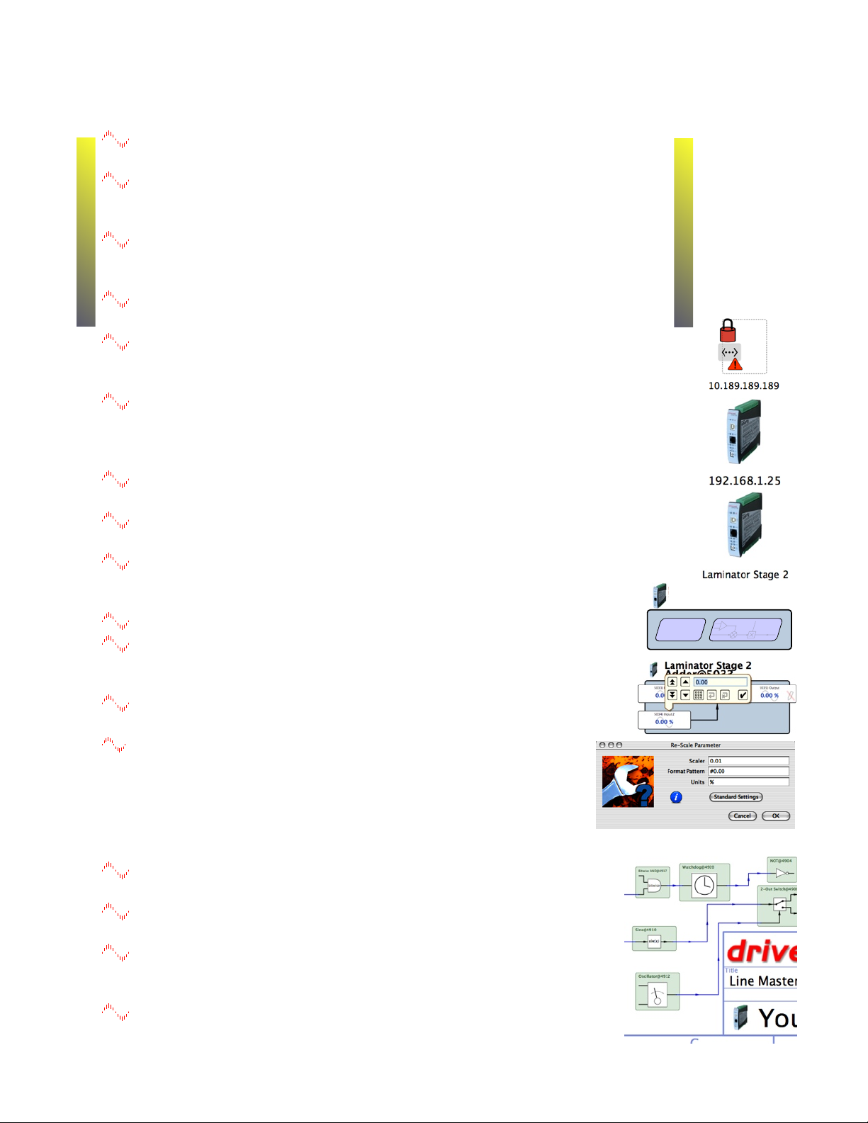
Get started with savvy
Laminator Stage 2
Overview
Modbus
Function Block
Engine
!
Before proceeding with your systems designs it is very important to familiarize yourself
with savvy, the configuration software.
We strongly recommend that you read the introductory guides, “Getting Started with
savvy,” “Getting Started with savvy-SFD,” and , “savvy-SFD and the PL series
drive.” Find these guides under the Help menu.
Use the unique, “ Create Phantom,” feature to practice your design and
configuration techniques. Design a system in any Phantom drive.web
device and export it for use in your devices.
We also strongly recommend that you attend one of our regular on-line training
seminars. Contact us at [email protected] or call 410-604-3400 to register.
Under the Directory menu, click on, “Discover All Local Devices.”
If your smarty is powered up and physically connected to the same
local network as your computer, an icon should appear on the screen.
If the red padlock icon at right appears, your computer’s subnet mask is
preventing communication with the smarty. Under the File menu, click,
“Administrate - Set IP Addresses for System.” A list will appear with a serial
number that should match the label on the bottom of your smarty.
Enter a unique IP address that is within your computer’s subnet mask. A
smarty icon should now appear with the IP address underneath.
Right click on the icon and choose, “Change Name,” to name your smarty for
easy identification. Now left click on the icon to view and configure.
The first level under the icon is the device overview screen. You will
see the Block Engine and if you have option-02 or -17 to -23, a
Modbus icon. Left click on icons to drill to the function block level.
Left click on function blocks to view and adjust parameters.
Left click on parameters to open the setter box unless they show
a crossed-out pen meaning that they are read-only. You can
adjust the parameter value with mouse or keys.
Right click on parameters to get info, add to a dock, copy, start
or end connections, rename, and rescale.
drive.web works with 16 bit words allowing raw decimal integer
values 0 to 65535 or ±32767. These raw values are limited and/or
scaled depending on the parameter. This prevents illegal values and
presents numbers in the most useful formats. Right click to adjust
scaling to fit your needs. Check scaling when making connections.
Upgrade savvy with Signal Flow Diagram Option - SFD
smarty HG502055 v. 5.1! ! www.driveweb.com ! ! ! ! Page 5/8
With savvy-SFD, implement your systems in a graphical manner and create
professional quality engineering drawings that are stored in your smarty.
Set borders, “drag and drop,” connections, zoom pan and see your system clearly.
Multi-page drawings with cross-referencing and annotation are easy to create.
You can get the savvy-SFD upgrade on-line under the
Commerce menu. Select, “Upgrade savvy,” and install by
processing a Voucher, coupon or credit card.
Find a useful guide to this upgrade, “Getting Started with
savvy-SFD,” under the help menu.
Page 6
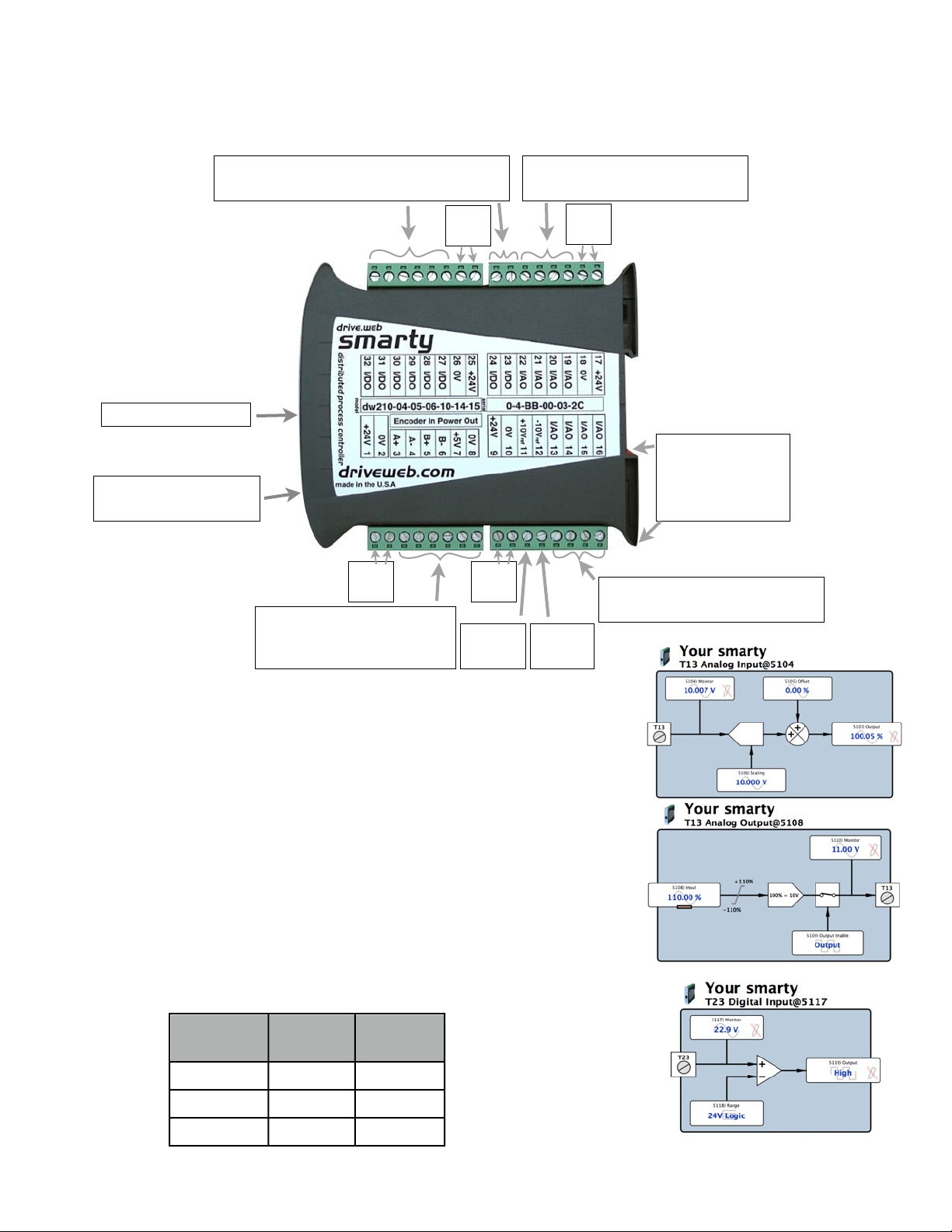
smarty Connections
0V
0V
0V
0V
Option Section or Manual.
Digital
Input Range
Turn On
Threshold
Turn Off
Threshold
5V
0.83V
2.5V
12V2V6V
24V
4V
12V
T23,24, T27-32, 8 Digital Input/Outputs
with Analog Monitoring
T19-T22 Analog Inputs or
Analog Output with Monitoring
Ethernet RJ45 8P8C
Chassis Ground (Earth)
Do NOT use for 0V
+24V
T3-T8 Option Dependent.
Direct Encoder Shown. See
+24V
+24V
+10Vref
T11
+24V
DIN Rail Clip.
Release with small
flat blade screw
driver at bottom
T13-T16 Analog Inputs or
Analog Output with Monitoring
T12
-10Vref
smarty Analog and Digital I/O
Analog Input Function Block
±25V max. 16 bit resolution, 100kΩ input impedance. Available
for all 16 I/O terminals. Scaling and offset parameters condition the data
for the next processing step without additional function blocks.
Analog Output Function Block
±11V and 10mA max output. 16 bit resolution. Eight terminals;
T13-16 and T19-22. Dynamically enable the output driver with Output
Enable parameter. Send a 0 for Input or 1 for Output.
Digital Input Function Block
Selectable Ranges 5V, 12V & 24V, 100kΩ input impedance.
Available for all 16 I/O terminals. Threshold Voltages:
smarty HG502055 v. 5.1! ! www.driveweb.com ! ! ! ! Page 6/8
Page 7
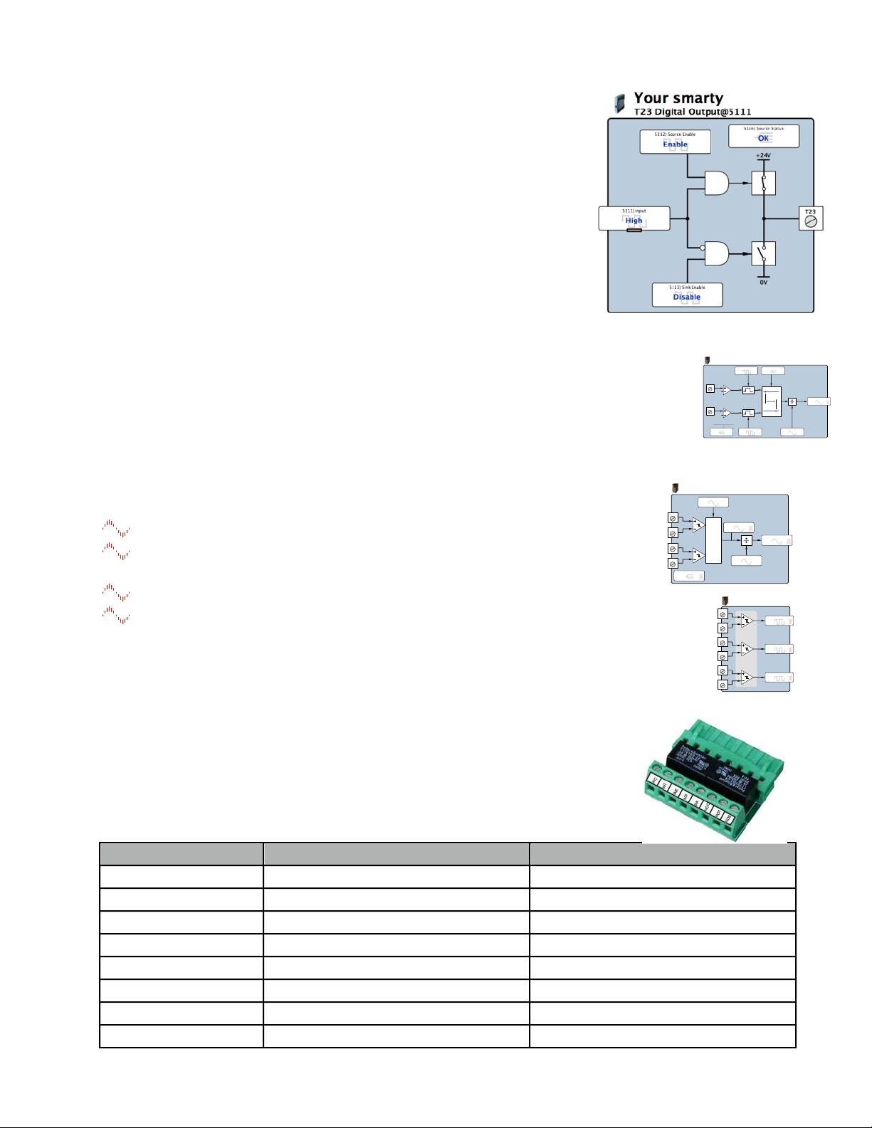
Digital Output Function Block
smarty w/ encoder
ENC1 Speed@5106
A
B
B1
B2
B3
B4
5106) Status
OK
5107) Pulses Per Revolution
1024 ppr
5108) Speed
0 RPM
5109) Base Speed
1800 RPM
5110) Output
0.00 %
smarty w/2 encoders+11
Registration@5102
! 8V
hysteresis ! 4V
C5
DIO1
! 8V
hysteresis ! 4V
C6
DIO2
5103) Master Edge
Rising Edge
5105) Measurement
Time ("s)
5102) Configuration
DIO1 & DIO2
5104) Slave Edge
Rising Edge
5106) Scaler
1
5107) Output
0
smarty w/ encoder
ENC1 Logic@5111
max voltage: ±25V
common-mode:
-10V to +13.2V
threshold:
0V ± 200mV
hysteresis: ! 45mV
B1
B2
B3
B4
B5
B6
5111) Output A
High
5112) Output B
High
5113) Output Z
High
HV Isolator Terminal
Function Blocks for T17-24 Position
Function Blocks for T25-32 Position
120VAC Input Common
Digital Input T19, T20, T21, T22
Digital Input T27, T28, T29, T30
120VAC Input 1
Digital Input T19
Digital Input T27
120VAC Input 2
Digital Input T20
Digital Input T28
120VAC Input 2
Digital Input T21
Digital Input T29
120VAC Input 2
Digital Input T22
Digital Input T30
NO Relay Common
Digital Output T23 and T24
Digital Output T31 and T32
Normally Open 1
Digital Output T23
Digital Output T31
Normally Open 2
Digital Output T24
Digital Output T32
+24V, 50mA Source or Sink. Eight terminals; T23, T24 & T27-T32.
May be used as a, “push-pull,” or, “totem pole,” output.
Source drivers are self-protecting. In case of shut-down due to overheating or
over-current, a warning triangle will appear in the affected channel’s function
block and the Status parameter in that function block will change from OK
to Fault. Connect from the Source Status parameter to your fault contingency
system for critical applications.
Systems connecting a, “heavy load,” i.e. one that is not inherently impedance
protected or otherwise current limiting to a Digital Output in Sink Mode
should be fuse protected with a 0.5A fuse.
smarty Option 11 Encoder Control F. B. Library 4
Requires smarty Encoder Input Module with dual encoder option, dw230-02 or -03
Encoder Position Function Block absolute position measurement
Encoder Speed Lock Function Block provides a numerical speed error signal.
Encoder Registration Function Block measure time or pulse delay between markers.
smarty Option 15, Direct Encoder Input
Encoder inputs are EIA422/EIA485 receivers, up to 300KHz, 24V max.
Connect your encoder with shielded cable with individually shielded twisted
pairs such as Belden 8163. Ground the shield at only one end.
Two function block types provide bidirectional speed and logic information.
EIA422/485 signals are differential-balanced. The, “+,” line must swing negative
with respect to the, “-,” line for proper operation. A single sided logic signal
requires that the, “-,” terminal be biased at least 250mV higher than logic low at,
“+,” terminal and 250mV lower than the logic high.
smarty Option 24 High Voltage Digital I/O Isolator
Plug-in option. Fits at T17-24 or T25-32. Two NO relay contacts with shared
common and four photocoupled 120VAC digital inputs with shared common.
NO Contact Ratings: Resistive Load - 3A @ 30VDC, 3A @ 250VAC
Motor Load - 1.5A @ 120VAC, 0.9A @ 230VAC
Correct function block assignment in savvy depending on isolator position:
smarty HG502055 v. 5.1! ! www.driveweb.com ! ! ! ! Page 7/8
Page 8
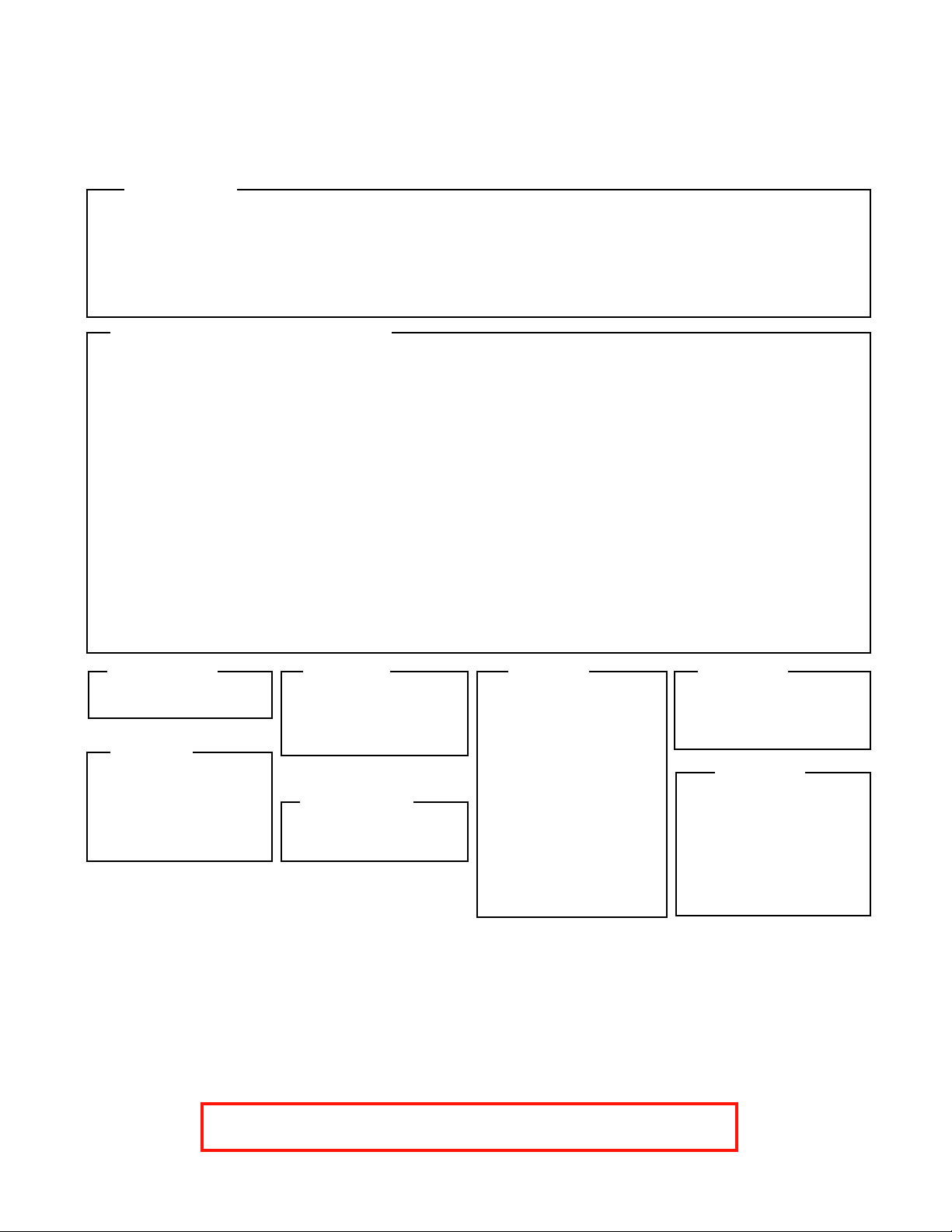
smarty Appendix A Function Blocks by Library and Option
Bold header indicates function block category. Number indicates # of active parameters inside the block.
Basic smarty
Arithmetic
3 Adder
3 Divider
3 Multiplier
3 Subtracter
Clamps
4 Clamp
Process Control Library Option 05
Arithmetic
3 Differential Splitter
4 Multiplier-Divider
3 Sign And Value
3 Sign Changer
Clamps
5 Clamp with Monitor
4 Deadband
4 Skipband
Comparators
4 Comparator
5 Equality Comparator
3 Maximum
3 Minimum
6 Window Comparator
Control
6 Differentiator
8 Integrator
Option 02, 04
Utility
4 Modbus Indirect
Option 03
I/O
2 AOP’s
3 DIO’s
5 UIP Differential
5 UIP Analog
3 UIP Logic
Control
15 PI
Drive Helper
11 Optidrive Helper
Logic Gates
3 AND
2 NOT
15 PI
20 PID
8 Profiler
Counters
17 Up/Down Counter
Drive Helper
11 Optidrive Helper
Filters
4 Low Pass Filter
5 Moving Average Filter
Latches
4 D Latch
5 D Latch with Reset
5 D Latch with Set
6 D Latch w/Set, Reset
3 SR Latch
4 T Latch
Option 06
Winder
18 Diameter Calculator
7 Taper Tension
30 Torque Compensator
Options 07,08
I/O
3 ENC Logic
5 ENC Speed
3 OR
Switches
4 2-In Switch
4 2-Out Switch
Utility
1 Dev. Comms Monitor
1 Indicator
Logic
17 16-Bit Binary Encod.
17 16-Bit Binarty Decod.
5 4-Bit Binary Encoder
16 4-Bit Priority Encod.
3 Bitwise AND
2 Bitwise NOT
3 Bitwise OR
3 Bitwise Shift
3 Bitwise XOR
Logic Gates
3 NAND
3 NOR
3 XNOR
3 XOR
Ramps
7 Linear Ramp
11 MOP
Option 10
Math
2 ArcCosine
2 ArcSine
2 ArcTangent
2 Cosine
2 Cube
2 Cube Root
2 Exponential
2 Logarithm
2 Reciprocal
2 Sine
2 Square
2 Square Root
2 Tangent
4 Parameter Block
6 Watchdog
1 Watchdog Driver
17 S Ramp
Switches
18 16-In Switch
18 16-Out Switch
6 4-In Switch
6 4-Out Switch
10 8-In Switch
10 8-Out Switch
3 Track and Hold
Timers
5 Delay-Off Timer
5 Delay-On Timer
3 One Shot
5 Oscillator
8 Underlap
Utility
4 User Logger
Option 11
I/O
5 ENC Position
6 ENC Speed Lock
7 Registration
Option 12
ModbusRTU Master
7 Comms Port
48EurothermERCFW09
6 Holding Reg. INT16
6 Holding Reg. UINT16
54 Optidrive Plus
54 Optidrive VTC
48 WEG CFW09
Appendix B drive.web Product Line Overview
smarty distributed process controller simultaneously manages varied process components and drives.
speedy sp and speedy485 Processing power, tailored for your drive or generic, Ethernet, EIA485
savvy Signal Flow Diagram Option Easily implement your systems designs. “Drag n’ Drop,”
connections with complete, graphical documentation created in one step and stored in your device.
drive.web Training Courses An essential component in your drive.web system. On-line and factory
courses are available at all technical levels. Sign up and get the most out of your drive.web technologies.
drive.web 4/116 Crockford Street, Northgate, QLD 4013 AUS.
Ph. 61(0)7-3256-8177, Fax 61(0)7-3256-8711, www.invertek.com.au
smarty HG502055 v. 5.1! ! www.invertek.com.au! ! ! ! Page 8/8
 Loading...