

Drive DeVilbiss Sidhil Athena Quick Glance User Manual
Quick Glance User Guide
(Fig. 1)
(Fig. 2)
5. Ensure the CPR dial is rotated to a closed position
(Fig. 3) .
5. Attach pump power lead to mains power outlet,
running power lead along the cable tidy
(Fig. 4 & 5)
7. Switch on.
8. The low pressure indicator will illuminate whilst the
mattress is inflating which will complete after
approximately 40 mins
CYCLE FAULT
POWER FAILURE
LOW PRESSURE
LOCK
STATIC
ALTERNATINGMUTE
S
O
F
T
M
E
D
I
U
M
F
I
R
M
COMFORT RANGE
1. Place mattress directly onto the mattress platform
ensuring umbilical cord is at foot end and ‘feet’ symbol is
facing up.
2. Attach straps to moving parts of bed frame making
sure they are not twisted.
(Fig. 1)
3. Position control unit on foot board of bed using the
integral brackets or on a firm surface.
(Fig. 2)
4. Attach umbilical cord to control unit by aligning with
the port on control box and pushing into place.
SETUP
The Apollo mattress is a 2 cell alternating Dynamic Replacement with a patient weight limit of 30st (190kg). It is suitable for
patients up to and including category 4 pressure ulcers with frequent monitoring and repositioning.
Contraindications: Appropriate advice should be taken for patients with unstable spinal injuries. Do not use the mattress if the
patient and accessories exceed patient weight limit (MUW).
5. Ensure the CPR dial is rotated to a closed position
(Fig. 3) .
5. Attach pump power lead to mains power outlet,
running power lead along the cable tidy
(Fig. 4 & 5)
7. Switch on.
8. The low pressure indicator will illuminate whilst the
mattress is inflating which will complete after
approximately 40 mins
CYCLE FAULT
POWER FAILURE
LOW PRESSURE
LOCK
STATIC
ALTERNATINGMUTE
S
O
F
T
M
E
D
I
U
M
F
I
R
M
COMFORT RANGE
(Fig. 2)
5. Ensure the CPR dial is rotated to a closed position
(Fig. 3) .
5. Attach pump power lead to mains power outlet,
running power lead along the cable tidy
(Fig. 4 & 5)
7. Switch on.
8. The low pressure indicator will illuminate whilst the
mattress is inflating which will complete after
approximately 40 mins
CYCLE FAULT
POWER FAILURE
LOW PRESSURE
LOCK
STATIC
ALTERNATINGMUTE
S
O
F
T
M
E
D
I
U
M
F
I
R
M
COMFORT RANGE
1. Place mattress directly onto the mattress platform
ensuring umbilical cord is at foot end and ‘feet’ symbol is
facing up.
2. Attach straps to moving parts of bed frame making
sure they are not twisted.
(Fig. 1)
3. Position control unit on foot board of bed using the
integral brackets or on a firm surface.
(Fig. 2)
4. Attach umbilical cord to control unit by aligning with
the port on control box and pushing into place.
SETUP
The Apollo mattress is a 2 cell alternating Dynamic Replacement with a patient weight limit of 30st (190kg). It is suitable for
patients up to and including category 4 pressure ulcers with frequent monitoring and repositioning.
Contraindications: Appropriate advice should be taken for patients with unstable spinal injuries. Do not use the mattress if the
patient and accessories exceed patient weight limit (MUW).
5. Ensure the CPR dial is rotated to a closed position
(Fig. 3) .
5. Attach pump power lead to mains power outlet,
running power lead along the cable tidy
(Fig. 4 & 5)
7. Switch on.
8. The low pressure indicator will illuminate whilst the
mattress is inflating which will complete after
approximately 40 mins
CYCLE FAULT
POWER FAILURE
LOW PRESSURE
LOCK
STATIC
ALTERNATINGMUTE
S
O
F
T
M
E
D
I
U
M
F
I
R
M
COMFORT RANGE
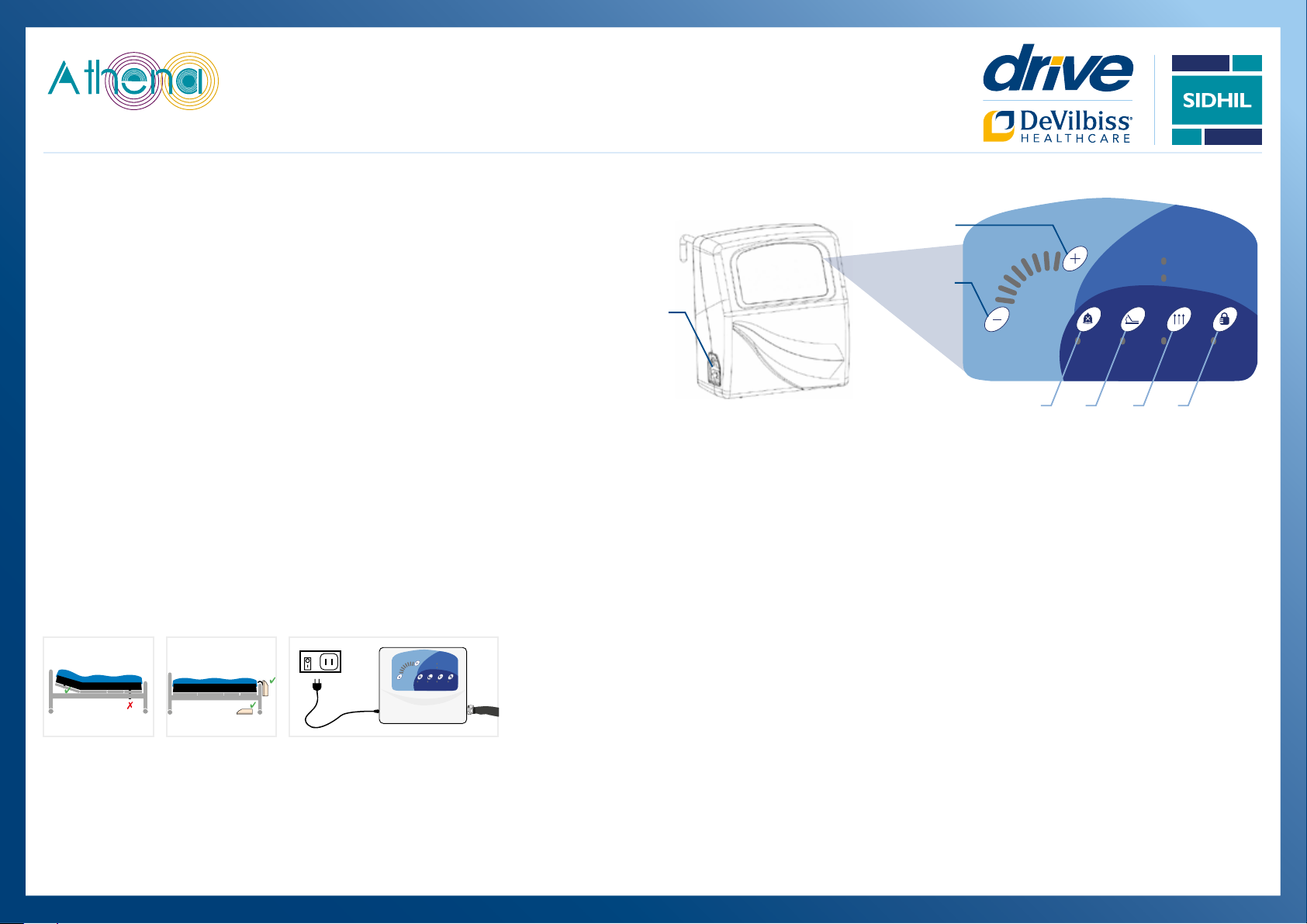
PRESSURE RANGE (mmHg)
MUTE SEAT AUTOFIRM LOCK
POWER FAILURE
LOW PRESSURE
10
25
POWER FAILURE
LOW PRESSURE
POWER FAILURE
LOW PRESSURE
PRESSURE RANGE (mmHg)
MUTE SEATAUTOFIRMLOCK
POWER FAILURE
LOW PRESSURE
10
25
4. Attach umbilical cord to control unit by aligning with
the port on control box and pushing into place.
5. Attach pump power lead to mains power outlet (Fig. 3)
7. Switch on.
8. The low pressure indicator will illuminate whilst it is
inflating, which will take approximately 2-3 minutes.
B
A
C
B
D E F
The Athena low air loss mattress system is a high quality air support
surface suitable for individuals with up to and including grade 4 pressure
ulcers, needing frequent monitoring and positioning. A controlled rate of
air escaping through the air cells is intended to reduce excess moisture
between the patient and mattress to minimise the risk of skin breakdown
and to provide a cooling eect to the body. Via the pressure distribution
in the air cells the mattress forms around the pressure points of the body
providing comfort and pressure reduction to vulnerable tissue.
Contraindications: Appropriate advice should be taken for patients
with unstable spinal injuries. Do not use the mattress if the patient and
accessories exceed patient weight limit (MUW).
1. Place mattress directly onto the mattress platform
ensuring umbilical cord is at foot end and ‘feet’
symbol is facing up.
2. Attach straps to moving parts of bed frame
making sure they are not twisted. (Fig. 1)
3. Position control unit on foot board of bed using
5. Attach pump power lead to mains power outlet
(Fig. 3)
7. Switch on.
8. The low pressure indicator will illuminate whilst
it is inflating, which will take approximately 2-3
minutes.
the integral brackets or on a firm surface. (Fig. 2)
4. Attach umbilical cord to control unit by aligning
with the port on control box and pushing into place.
Fig. 1 Fig. 2 Fig. 3
Leaflet Code: LL280
Need Assistance?
Call 01422 233 136 (8:30am - 5pm)
or 0800 037 0234 (out of oce hours)
25
POWER FAILURE
LOW PRESSURE
10
PRESSURE RANGE (mmHg)
MUTE SEATAUTOFIRMLOCK
Operation
A. Power
The switch on the side of the pump turns it on/o.
When switched on an audible signal will sound for a
brief period and the switch illuminates green.
B. Pressure Range
Press + or - to increase or decrease the pressure
setting depicted on the pressure scale. There
are 8 available pressure settings from soft to firm
(10mmHg to 25mmHg, ±2mmHg per step). The
green lights illuminate on the pressure scale to
indicate what pressure setting has been chosen..
C. Mute
Mutes the audible signal for a 30 minute period.
The mute setting will self-cancel after 30 minutes
and the audible signal will re-sound. Note: If the
‘power failure’ indicator activates the mute button
will not silence the audible signal. To silence, the on/
o switch on the control unit must be set to
‘o’. Please ensure it is turned on again to inflate
the mattress.
D. Seat
Increases the pressure in each cell by 5mmHg.
The ‘seat’ mode prevents the patient from
bottoming out when the patient is in a sitting
position. When in ‘seat ’ mode an amber indicator
illuminates. Re-pressing the button cancels
‘seat’ mode.
E. Autofirm
Automatically inflates the mattress to a maximum
level of 45mmHg to aid patient transfers. When in
‘autofirm’ mode an amber indicator illuminates.
‘Autofirm’ self-cancels af ter 30 minutes and returns
to the previous pressure setting. Re-pressing the
‘autofirm’ or pressure adjustment buttons cancels
‘autofirm’ mode.
F. Lock/unlock
The control unit will automatically lockout all
functionality 2 minutes after a function change.
To unlock the control unit the ‘lock’ button is
pressed for 2 seconds. To reengage the lock the
button can either be again pressed for 2 seconds
re-engage. When the system is locked an amber
indicator illuminates.
or the user can wait for the automatic lock to
Quick Glance User Guide
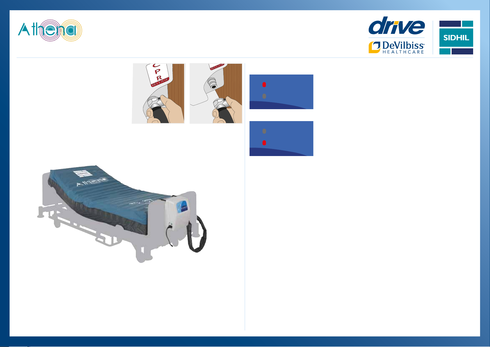
CPR
Rapid deflation of the mat tress may be required for
emergency treatment or system deflation.
Press the button on the connector and while holding
down pull the air pipe o the receptacle on the side
of the control unit.
Trouble Shooting - Fault Indicators
Power failure:
POWER FAILURE
LOW PRESSURE
POWER FAILURE
LOW PRESSURE
A red indicator illuminates and an audible signal sounds if a power failure
occurs. Check mains cable is plugged in and switched on. Check mains
cable is attached to the pump.
Low pressure:
A red indicator illuminates and an audible signal sounds if the pressure
becomes unacceptably low. Ensure the mattress air connector is correctly
connected to the control unit.
Leaflet Code: LL280
Need Assistance?
Call 01422 233 136 (8:30am - 5pm)
or 0800 037 0234 (out of oce hours)
 Loading...