

Page 1

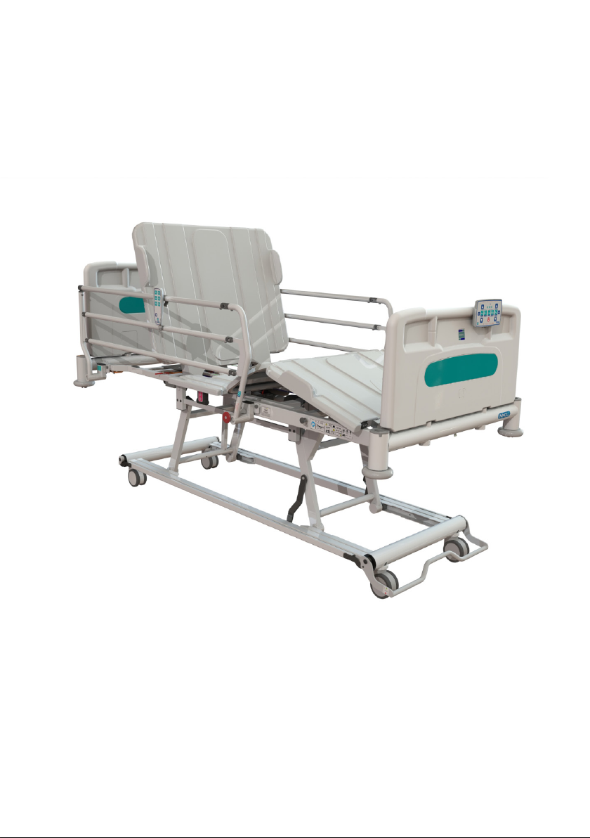
Innov8 Low General Ward Bed
Instructions for use
Page 2

234
Page 3
Page 4

CONTENTS
1. INTRODUCTION 6
2. CONTACT INFORMATION 6
3. PRODUCT DESCRIPTION 7
3.1 Environment 7
3.2 Intended Patient Group 7
3.3 Intended Use 7
3.4 Product Overview 8
3.5 Features 8
4. SAFETY 9
4.1 Warnings & Cautions 9
4.2 Risk Assessment 9
4.3 Contraindications 10
4.4 Bed Loading 10
4.5 Training 11
4.6 General Warnings 11
5. TRANSPORT & STORAGE 12
6. SYMBOL DEFINITION 13
7. PARTS IDENTIFICATION 15
8. INSTALLATION & PREPARING FOR USE 16
9. OPERATION OF THE BED 18
9.1 Operational Limits 18
9.2 General Safety 18
9.3 Brake & Steering System 19
9.4 Moving the Bed 20
9.5 Side Rails & Mattresses 22
9.6 Side Rail Safety 22
9.7 Operating the Side Rails 23
9.8 Bed Extension 24
9.9 Emergency CPR Function - Manual 26
9.10 Bed Ends 27
9.11 Mattress Panels 27
9.12 Electrical Operation of the Bed 28
9.12.1 Carer Handset Layout 28
9.12.2 Operating the Carer Handset 30
9.12.3 Function Lockout 30
9.12.4 Platform Height 31
9.12.5 Backrest 31
9.12.6 Leg Section 32
9.12.7 Auto Contour 33
9.12.8 Tilt 33
9.12.9 Cardiac Chair 34
9.12.10 Electrical CPR 34
9.12.11 Mains Power Indicator 35
9.12.12 Battery Indicator 35
Page 5

9.12.13 Patient Handset 36
10. ADDITIONAL FEATURES 37
10.1 Equipotential Stud 37
10.2 Corner Sockets 37
11. DECONTAMINATION 38
11.1 Cleaning & Disinfection Guidelines 38
11.2 Steam Cleaning 39
12. MAINTENANCE 40
12.1 General Inspection 40
12.2 Fault Finding 41
12.3 General Maintenance 42
13. DISPOSAL OF PARTS & ENVIRONMENTAL CONSIDERATIONS 44
14. ELECTROMAGNETIC COMPATIBILITY (EMC) 45
15. SPECIFICATION 46
15.1 Bed Specification 46
15.2 Performance Characteristics 47
16. ACCESSORIES 48
16.1 Mattress / Side Rail Compatibility Chart 49
17. WARRANTY 50
18. NOTES 51
5
Page 6

1. INTRODUCTION
Thank you for purchasing a Drive DeVilbiss Healthcare Innov8 Low general ward
bed. For safety reasons it is imperative that these instructions are read and fully
understood before the bed is used for the first time. For assistance in setting up, using
or maintaining your bed or to report unexpected operation refer to the contact details
found in section 2.
2. CONTACT INFORMATION
For any service, warranty, sales or customer service information on this product
please contact your provider or if in doubt contact Drive DeVilbiss Healthcare Ltd.
at the following address:
Drive DeVilbiss Healthcare Ltd.
Heathfield Lane
Birkenshaw
West Yorkshire
BD11 2HW
UK
Please quote the product serial number on all correspondence.
Service & Maintenance:
Tel: +44 (0)1422 233136
Fax: +44 (0)1422 233010
Customer Service:
Tel: +44 (0)845 0600 333
Fax: +44 (0)845 0600 334
Spares:
Tel: +44 (0)1422 233136
Fax: +44 (0)1422 233010
customer.service@drivedevilbiss.co.uk
www.drivedevilbiss.co.uk
For Service & Support outside the UK & Northern Ireland please contact the local
distribution company from where this equipment was purchased. Failure to do so
may result in the product warranty becoming void.
6
Page 7

3. PRODUCT DESCRIPTION
3.1 Environment
The Innov8 Low bed is intended for use in a hospital where acute/intensive care is
provided and medical supervision and monitoring is required.
3.2 Intended Patient Group
The bed frame is intended for an adult who is up to 190kg in weight. A lower (or
upper) age limit is not defined as it depends on the physical size of the patient in
relation to the various proportions and gaps around the bed frame. Patients must be
in excess of 146cm in height ranging up to 205cm (bed extended) and have a BMI
greater than 17.
3.3 Intended Use
The intended use of the bed is for sleeping / resting and it is intended to assist in
diagnosis, monitoring, prevention, treatment, alleviation of disease or compensation
for an injury or handicap, as determined by the end user and care staff.
The bed frame is intended to support a single adult. A risk assessment must always
be performed on the suitability of the patient to the bed frame and any ancillary
accessories.
The patient is only defined as such when situated in the bed. Both the professional user
and patient are intended to operate the bed. It is the professional user’s responsibility
to determine that the patient is both mentally and physically capable of operating the
bed functions with minimal risk of personal injury.
The bed is intended to provide patients with optimum independence and freedom of
movement and carers with greatly reduced manual handling needs via the electrically
operated movable sections.
For assistance in setting up, using or maintaining your bed or to report unexpected
operation refer to the contact details found in section 2.
7
Page 8

3.4 Product Overview
The Innov8 Low bed is intended to be plugged into a permanent mains supply however
it also has a battery backup system for such times that a mains supply is not available.
The bed has two separate handsets, one for the carer with full control capability and
one for the patient with limited functionality and limited height adjustment. The carer
has the ability to lock out individual functions to reduce the risk of accidental operation.
The handsets operate an electronic linear actuator system which is controlled via a
central control box. The actuators are attached to the moving parts of the bed frame
allowing the bed to be operated via the use of either handset.
The powder coated platform supports the full electrical system, five removable plastic
platform panels, two plastic bed end boards and a set of side rails to provide patient
protection; the bed has a safe working load of 255kg. The bed is manoeuvrable via
the aid of four linked castors attached to the base frame of the bed which in turn is
attached to the platform frame via two lift arms.
3.5 Features
• Electrically operated height, backrest and leg section adjustment.
• Auto regressing backrest.
• Electrically operated head and foot down tilt (Trendelenburg & reverse
Trendelenburg).
• Auto-contour – simultaneous adjustment of the backrest and knee-break.
• Cardiac chair position.
• Battery backup.
• Patient handset and carer handset with integral function lockout.
• Removable head and foot ends.
• Removable mattress platform panels.
• Mattress platform extension.
• Castor system with brake, free and tracking modes.
8
Page 9
4. SAFETY
4.1 Warnings & Cautions
Warnings in this user manual highlight potential hazards that if
disregarded could lead to injury or death.
Warning
Cautions in this user manual highlight potential hazards that if
disregarded could lead to equipment damage or failure.
Caution
4.2 Risk Assessment
Before a patient uses the bed a risk assessment must be performed on a patient by
patient basis. The risk assessment should include, but is not limited to:
• Entrapment.
• Falling out of the bed.
• Small adults (and children).
• Patients with learning difficulties.
• Very active patients.
• Unauthorised people.
• Use of side rails.
• Items/equipment/cables under the bed.
Warning
Bed functions must be locked out if there is any doubt about the ability
of the patient to operate the bed safely.
9
Page 10
4.3 Contraindications
Patient conditions for which the use of the bed is a contraindication are as follows:
• Cervical or skeletal traction – If bed functions remain unlocked.
• Unstable spinal fractures – If bed functions remain unlocked.
• General skeletal fractures – If relevant bed functions remain unlocked.
• Mental capacity not sufficient to operate handset functions safely – If bed functions
remain unlocked.
• Confused, agitated or restless – If side rails fitted and/or in raised position.
• Exceeds maximum patient weight of bed.
• Less than 146cm in length.
Other contraindications may be relevant which are specific to the patient or care
environment.
4.4 Bed Loading
• The safe working load of the bed is: 255kg (40 stone)
• The maximum patient weight of the bed is: 190kg (30 stone)
Safe Working Load is the sum of:
• Patient mass
• Mattress mass
• Accessories mass
• Mass supported by the accessories (excluding patient mass)
Warning
The maximum loads shown above are for the bed to be occupied by one
person only. The bed is not designed to take the weight of visitors sitting
on the side of the bed. Additional weight could damage components or
cause the bed to overturn, causing injury.
10
Page 11
4.5 Training
All users of this bed are to be suitably trained prior to use and patients are to be
familiarised with handset and bed functionality at the earliest opportunity. It is the
responsibility of the end user to ensure they have received sufficient training to use the
bed and any associated accessories safely and correctly.
For further information in regards to training options please contact Drive DeVilbiss
Healthcare Ltd. or your local provider (see section 2).
4.6 General Warnings
• The bed is to be installed and put into service in accordance with
the information provided in these instructions for use.
• The bed is typically not suitable for child use, if it is to be used
for child occupancy ensure a risk assessment has been undertaken
taking into account the proportions of the child and dimensions of
the bed frame.
• The bed is designed for occupants who are 146cm or longer in
length; if a person shorter than this length is put on the bed a full
and detailed patient specific risk assessment must be carried out,
taking the proportions of the bed frame and side rails into particular
consideration.
• Misused electrical equipment can be hazardous.
• Accessories that have not been approved or designed for use with
the bed are not be used.
Warning
• Modification of the bed frame is not allowed without the permission
of Drive DeVilbiss Healthcare Ltd.
• The bed is not to be used in the presence of flammable gasses or
used in oxygen rich environments.
• The bed is not to be used in an operating theatre.
• If children or adults with learning difficulties pose a potential risk
of intentional or unintentional tampering with the bed its suitability
for use is to be considered during the initial patient / product risk
assessment.
• The RF emissions from the electrical system are very low and are
not likely to cause any interference to nearby electronic equipment,
however interference to sensitive equipment is possible (see
section 14 for further detail).
11
Page 12
5. TRANSPORT & STORAGE
The following conditions should be followed when transporting and storing the Innov8
Low bed. Note, this does not apply to the transfer of the bed between wards and / or
when the bed is in use (see section 9.4).
• Bed set to lowest height.
• Bed always to be stored on a flat and level floor.
• Platform extension retracted.
• Brakes applied.
• All profiling sections secured (transport only).
• All functions locked out.
• Covered to protect from fluid ingress, dirt, dust etc.
• Instructions for use retained with bed.
• Environmental conditions for transport and storage:
Ambient temperature: -10°C to +50°C
Humidity: 20% - 90% at 30°C - not condensing
Atmosphericpressure: 70kPato106kPa(altitude≤2000m)
• To prevent the risk of cross infection, when removing a bed from
use ensure that all activities in relation to the bed and its ancillary
parts are carried out using disposable gloves and that they are then
discarded appropriately, unless it can be verified that the bed and
the ancillary parts have been suitably cleaned and disinfected prior
Warning
to collection.
• Prior to putting into storage ensure the bed has been cleaned and
disinfected in line with the local infection control policy and / or as
defined in section 11 of these instructions for use.
Caution
• Beds must not be stored one on top of another or on their side.
• Care is to be taken when pushing the bed over thresholds.
• Do not use the side rails to move the bed – Risk of product damage.
12
Page 13
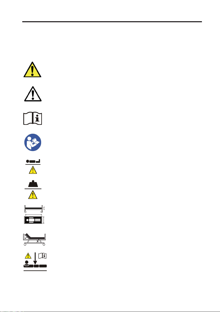
6. SYMBOL DEFINITION
The following symbols are found on this bed:
(See section 9.12 for handset symbols)
Symbol
Description
Warning
Beware of potential hazard
Caution
Beware of potential product damage
Refer to instructions for use - Recommended
Failure to read the instructions for use could introduce a hazard
Refer to instructions for use - Mandatory
Failure to read the instructions for use could introduce a hazard
Maximum patient weight
Refer to section 4.4
Safe working load
Refer to section 4.4
Mattress suitability
Refer to section 16
Dynamic mattress strapping suitability
Refer to section 16
Low height warning
13
Page 14

Symbol
40 kg
BMI 17
146 cm
Description
Equipotential stud
Minimum patient weight
Minimum patient BMI
Minimum patient height
Type B applied part
Lot number
REF
Product code
Date of manufacture
Manufacturer
W.E.E.E Label - Found on individual parts of electrical system
(Waste Electrical and Electronic Equipment) Refer to section 13
14
Page 15
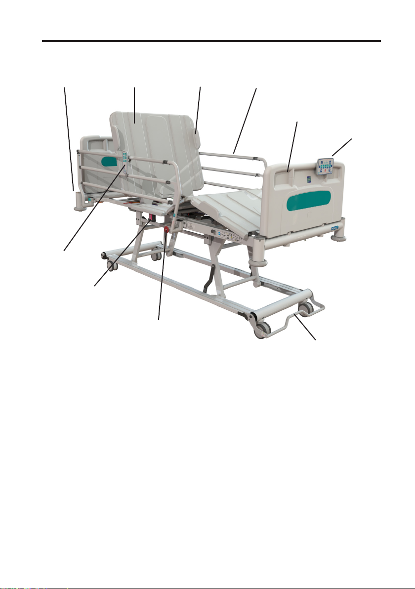
7. PARTS IDENTIFICATION
Accessory
mounting points
Patient
handset
Manual CPR
handle
Removable
mattress panels
Bed extension
release plunger
Mattress
retainers
Safety side
rails
Removable head
and foot ends
Carer handset
Brake bar
15
Page 16
8. INSTALLATION & PREPARING FOR USE
Prior to operating the bed for the first time the following simple steps must be
performed:
• Ensure the wooden packing boards are removed from the bed prior to connecting
to the mains supply – See section 13 for disposal of the packing boards.
• Ensure the bed and all accessories are at room temperature.
• Ensure the bed has been cleaned and disinfected (see section 11).
• Ensure the brakes have been applied (see section 9.3).
• Connect the mains cable to an appropriate mains socket outlet.
• With the bed plugged into the mains supply allow it to remain inactive for 6hrs.
This is to allow the bed frame and electronic system to adjust to the environmental
conditions of the room.
• The bed is to be left in its lowest position when the patient is
unattended in order to reduce the risk of injury due to a fall.
• Before operating the bed ensure the patient is positioned
appropriately ensuring all limbs are clear of moving parts.
• The mains plug is the disconnect device for the means of isolating
the bed from the mains supply, the plug must be accessible at all
times.
• Ensure the mains cable is plugged into an appropriate power
source at all times.
• To avoid the risk of an electric shock, this equipment must only be
connected to a supply mains with protective earth.
• Ensure the electrical cables are not in tension, paying particular
attention to the mains cable.
Warning
• Ensure that all cables are clear of all moving parts to prevent
damage to the electrical components.
• Inappropriate handling/positioning of the mains cable could cause
kinking or shearing of the cable which may lead to exposed live
wires, creating an increased risk of electrocution.
• Precautions are to be taken when routing cables from external
equipment around the bed to ensure that they do not become
squeezed, trapped or damaged.
• A CE marked extension cable must only be used when it is not
possible to reach a wall socket with the mains cable – Contact
Drive DeVilbiss Healthcare Ltd. for detail with regards to the safe
use of extension cables.
16
Page 17

Warning
Caution
• If an extension cable is used never overload it by plugging in
appliances that together will exceed the maximum current rating
stated for the extension cable.
• Block adaptors are not to be used.
• Ensure socket outlets are not positioned under the bed frame.
• Any electrical component that is part of the bed frame or associated
ancillary equipment that is found to be damaged must be replaced
immediately, due to the risk of electrocution.
• Consideration is to be taken in the positioning of the bed cables
and handset cable to minimise the risk of accidental strangulation
resulting from occupant entanglement.
• Keep the bed away from sources of heat and naked flames (e.g.
cigarettes, electric fires, fan heaters etc.).
• Ensure that any mattresses used are of the correct size and type
and have been fitted correctly – Incorrect mattress specification
could lead to an entrapment and / or falls hazard.
• Ensure the mattress is compatible with the side rails (if fitted).
• Special care is to be taken when fitting a dynamic mattress to the
bed as incorrect fitting could damage the bed (see section 16).
• Ensure the bed is positioned an appropriate distance from walls/
other furniture to prevent damage or patient injury when operating
the bed (particularly when operating in tilt).
• Ensure the mains supply is compatible with the control unit (see
section 15.2 for electrical specification).
17
Page 18

9. OPERATION OF THE BED
9.1 Operational Limits
• Ambient temperature: +5°C to +40°C
• Humidity: 20% - 90% at 30°C - not condensing
• Atmosphericpressure: 70kPato106kPa(altitude≤2000m)
9.2 General Safety
• Before operating the bed ensure the patient is positioned
appropriately and limbs are clear of moving parts.
• When a patient is left unattended the carer is to determine
whether the bed should be set to the minimum height allowed by
the patient handset (420mm) or lowered to minimum height using
the carer handset (225mm).
Warning
• When a patient is left unattended the carer is to determine
whether the side rails need to be raised or not.
• When a patient is left unattended the carer is to determine whether
the patient handset functions need to be locked out or not.
Caution
When the bed is operated, ensure that obstacles such as over-bed
tables and other furniture/objects are not causing an obstruction,
particularly when lowering to minimum height with the carer handset.
18
Page 19

9.3 Brake & Steering System
The brake bar at the foot end of the bed operates all four castors simultaneously.
Brake bar down (brake):
All four castors are locked - the bed
cannot move.
Brake bar horizontal (free):
All castors swivel freely - the bed can
move in any direction.
Brake bar up (track):
The head end castors are set in a specific
“tracking” position - the bed travels in a
straight line.
Track
Brake
Free
Brake Position Label:
The label on the base also indicates
which setting the castors are set to; the
brake bar will align with one of the three
markings depending on its setting.
19
Page 20

The brakes must always be engaged when the bed is stationary.
Warning
When the pedal is in the tracking position the mattress platform must
not be lower than 400mm from the floor. Lowering the mattress
platform to the minimum height with the pedal in the tracking position
Caution
9.4 Moving the Bed
Before moving the bed the following checks must be performed:
• Side rails are to be raised, to minimise the risk of a patient falling.
• The platform is to be horizontal.
• The platform is set to a suitable height for pushing.
• The mains cable must be unplugged from the wall and stored on the cable tidy
hooks on the back of the bed.
could lead to equipment damage.
20
Page 21

When moving the bed it is advisable to set the steering function to ‘track’ and to push
the bed from the foot end of the bed. This way, the person pushing the bed is able to
monitor the condition of the patient during transport and can keep the bed moving in
a straight line with minimal effort.
• If the bed is to be moved with a heavy occupant it is to be assessed
whether or not two qualified people should move the bed, this is
dependent on the situation and load on the bed.
• If the bed is to be pushed up / down a slope it is to be assessed
Warning
Caution
whether or not two qualified people should move the bed, with
one person at each end.
• Care is to be taken when pushing the bed over thresholds.
• Do not use the side rails to move the bed – Risk of product
damage.
21
Page 22

9.5 Side Rails & Mattresses
The Innov8 Low can be specified with two types of cantilever side rails (high & low);
this is to provide the optimum mattress / side rail combination for both foam and air
mattresses of varying thickness. When specifying a mattress and side rail combination
a clinical assessment of the patient’s needs must be carried out in line with the local
policy.
Side rails must only be used with a mattress of the correct size and type
that is approved for use with the Innov8 Low bed – Incorrect mattress
Warning
9.6 Side Rail Safety
The side rails available for the Innov8 Low are product specific, no other side rail is to
be used with the bed. Drive DeVilbiss Healthcare does not recommend the use of the
Innov8 Low side rails (and bed) when caring for individuals who are less than 146cm
in length, due to the potential risk of entrapment - It is the equipment provider’s
responsibility to ensure suitability for use.
Warning
specification can lead to an entrapment and / or falls hazard.
• Whilst every care has been taken to ensure that the design of the
Innov8 Low side rails meet the relevant safety standards, beds
fitted with side rails can still pose a potential risk of death from
entrapment and asphyxiation.
• A risk assessment is to be carried out to consider the age, mental
and physiological condition and size of the patient to assess side
rail suitability.
• All staff responsible for the purchase, selection for use, and
adjusting of bed side rails should be aware of the potential risk of
entrapment and asphyxiation when a bed is occupied.
• Care must be taken when positioning and adjusting side rails to
ensure that any spaces between the side rails, mattress or bed
frame do not allow entrapment of the occupant’s head or body.
• All staff responsible are to be aware that increased vigilance is
required when nursing patients in beds fitted with side rails.
• Side rails are not designed to act as restraints for patients.
• When side rails are to be used as a moving and positioning aid a
risk assessment is to be performed to assess the suitability of the
patient using the side rail as such.
• If forces beyond those expected during normal use are inflicted on
the side rail permanent deformation could occur, increasing the
risk of patient entrapment.
22
Page 23

9.7 Operating the Side Rails
When operating the side rails ensure they are free from obstructions,
to prevent injury/entrapment.
Warning
To Lower:
Hold the top rail and pull out the release plunger. Gently lower the side rail towards
the foot end of the bed.
To Raise:
Hold the top rail and lift the side rail until it locks into the vertical position.
Ensure the side rail release plunger is fully engaged when the side rails
are in the raised position.
Warning
When lowering do not drop the side rail – Risk of product damage.
Caution
23
Page 24

9.8 Bed Extension
The bed has an integral bed extension which allows the bed to be adjusted in length,
according to the patient’s needs. The length extension is typically for patients who
exceed 185cm in length and gives the bed compatibility with patients up to 205cm.
The length extension is only used for those individuals who require
it due to their physical height requirements, it is not to be kept in
the extended position as the default for all occupants. A patient risk
Warning
To extend the bed:
• If the bed is in tilt the platform must be levelled first (see section 9.12.8).
• Pull out the spring loaded plunger located on the side of the bed near the foot end
and, whilst holding it out, rotate it by a quarter turn (the plunger should stay out).
Repeat for the plunger on the opposite side of the bed.
• Pull out the mattress platform extension to its maximum extent.
• Rotate the spring loaded plungers until they lock back into position.
assessment must be performed to assess the need for the extension.
24
Page 25

• Pull out the leg extension to its maximum extent.
• If previously removed replace the bed end.
To retract the bed extension:
• Push the leg extension in.
• Pull out the spring loaded plunger located on the side of the bed near the foot end
and, whilst holding it out, rotate it by a quarter turn (the plunger should stay out).
Repeat for the plunger on the opposite side of the bed.
• Push the mattress platform extension fully in.
• Rotate the spring loaded plungers until they lock back into position.
Warning
Caution
• Always fit a mattress extension block when the platform is
extended.
• Always ensure the extension is locked in position, both in the
extended and retracted states.
Never pull the leg extension out without the mattress platform
extension pulled out – Risk of product damage.
25
Page 26

9.9 Emergency CPR Function - Manual
The backrest can be levelled using the manual CPR handles located on both sides of
the bed.
To flatten the backrest in an emergency, pull one of the red and black handles outwards;
the backrest will now drop into a flattened state.
CPR handle
(both sides)
Note: The platform will not level itself or change height when the manual handles
are pulled, this function is only available with the electrical CPR function (see section
9.12.10)
The backrest may fall quickly, ensure that limbs and equipment are clear.
Warning
Do not use the CPR handle as the default method for lowering the
backrest – Risk of product damage.
Caution
26
Page 27

9.10 Bed Ends
The bed has plastic end panels which are easily removable, allowing for fast patient
access. To remove, hold the panel with both hands and lift squarely.
The head and foot end panels are of different heights, the foot panel is shorter and
can be identified by the small foot motif on one side of the panel and must always be
placed at the foot end of the bed.
9.11 Mattress Panels
The mattress panels are held onto the tubular frame of the bed with loose fitting clips.
A light force should be used to fit and remove the panels.
The panels only fit in one orientation and position, if difficulty is experienced whilst
fitting, ensure the panel in question is correctly orientated and located.
Backrest
Seat
27
Thigh
Calf
Page 28

9.12 Electrical Operation of the Bed
9.12.1 Carer Handset Layout
Lock-Out
Button
Direction
Arrows
Raise/Lower
Platform
Backrest Leg
Section
CPR Auto-Contour
Mains Connection
Light
Battery Charging
Light
Contour & Tilt buttons)
Cardiac Chair Function
(press both the Auto-
Forward/Reverse
Trendelenburg
Direction
Arrows
Lock-Out
Button
28
Page 29

Warning
Caution
• The carer handset controls all bed functionality; it is to be used
only by the carer. The carer handset is intended to be stored at the
foot end of the bed by clipping it over the bed end panel, keeping
it out of reach of the bed occupant.
• Engage the lockout function if a patient could be injured due to
inadvertent motion of the mattress platform.
• Before lowering the bed ensure nobody is in close proximity to
the underside of the bed frame – Risk of crushing.
• Before profiling the platform ensure limbs are clear of the side
rails – Risk of injury.
• If the bed is continuously used for an extended period of time
and it exceeds the duty cycle the control box and/or lift actuators
may become temporarily disabled or irreparably damaged. If this
occurs remove the power supply from the wall and allow system
to rest for 20-30 minutes before attempting to re-operate.
• Ensure equipment and objects are clear of the base before
lowering – Risk of product damage.
29
Page 30

9.12.2 Operating the Carer Handset
Green light:
Function
active
9.12.3 Function Lockout
+
Amber
light:
Function
locked
To activate a function, press the desired function
button. A green light will illuminate at the top of the
function button, this indicates the function is now
active.
Once the function button is active hold down one of
the direction buttons, until the required position is
reached.
The function will stay active for 5 seconds. If after
5 seconds a direction button has not been pressed
the function will de-activate and the green light will
extinguish.
To lockout a function one of the padlock symbols must
be pressed simultaneously with the function to be
locked. An amber light will illuminate at the bottom of
the function button, this indicates the function is now
locked out.
To unlock a function the above process is repeated,
the amber light will extinguish.
When a function is locked out on the carer handset,
the patient handset will have the corresponding
function locked out.
Warning
Lockout all relevant functions if a patient could be injured due to
inadvertent motion of the mattress platform.
30
Page 31

9.12.4 Platform Height
The platform height button allows adjustment of the mattress
platform height.
The carer handset can be used to lower the mattress platform
to a lower height than can be achieved using the patient handset.
When the bed reaches a height of 420mm, a single auditory
signal will sound and the platform speed will slow to signify
to the carer that the bed is being operated in the low height
region and care should be taken to ensure that no equipment is
placed under the bed.
Note: The patient handset is only able to lower the bed to a height of 420mm. This
means that the patient is not able to operate the bed in the low zone.
• Before lowering the bed ensure nobody is in close proximity to
the underside of the bed frame, especially when travelling below
420mm – Risk of crushing.
Warning
Caution
• To reduce the risk of injury due to falls it is advised that the bed is
left in its lowest position when the patient is unattended.
If the bed is to be used with a hoist, ensure that the clearance under
the bed is sufficient during the required range of bed motion; there is
a risk of collision between the bed lifting mechanism and the hoist legs.
9.12.5 Backrest
Ensure limbs and equipment are kept free from the space under the
backrest before lowering – Risk of crushing. Any obstructions preventing
the backrest from lowering will bear the weight of the backrest, mattress,
Warning
and patient (if present) until removed from under the section.
The backrest button on the carer handset allows adjustment of
the backrest angle.
The backrest actuator is fitted with an anti-entrapment
mechanism and will stop lowering if it hits an obstruction. Once
the obstruction is removed, the backrest will lower again under
its own weight.
31
Page 32

9.12.6 Leg Section
The leg section button on the carer handset allows adjustment
of the leg section. When the function on the handset is operated
the height or angle of the section is adjusted, depending on
whether or not the leg stay bar is engaged.
In normal use the leg section operates in angle adjustment
mode where the thigh and calf sections angle upwards as the
function is operated, as depicted by the graphic on the button.
However the operation of the leg section is dependent on
whether the leg stay bar is engaged and can be set so that the
foot section rises parallel to the platform.
Setting the bed so that leg section height adjustment operates:
• Press the leg section button on the carer handset and raise to maximum height.
• Lift the leg section manually.
• Lift the leg stay bar.
• Position the leg stay bar into the channel under the foot section.
• The calf section will now lift as the function is driven up.
To disengage the leg stay bar, raise the foot section to its maximum height using the
carer handset, then lift the leg section manually so the leg stay bar disengages from the
channel under the foot section.
Thigh Section Angle Adjustment Leg Section Height Adjustment
32
Page 33

To minimise the risk of injury, before attempting to lift the calf section
either:
• Ensure there is no load on the section, or
Warning
Caution
9.12.7 Auto Contour
9.12.8 Tilt
• Support the calf section with a second able bodied person.
The leg section is only to be used for the lifting of a patient’s legs – Any
other use may damage the bed frame.
When the auto contour button is pressed both the backrest
and knee break functions operate together.
Note: If the backrest or knee break are locked out this will
automatically disable the auto contour function.
Head down tilt (Trendelenburg) and foot down tilt can be
applied using the carer handset.
Warning
Caution
When in tilt, in order to level the bed the opposite direction
button is pressed and held until the bed stops, the platform will
now be level.
To continue tilting the bed in the opposite direction, re-press
the same direction button again and hold until the desired angle
is reached.
Never leave a patient unattended when the bed is in head down tilt
(Trendelenburg).
When the bed is put into head down tilt ensure there is sufficient
space behind the bed to ensure the head board and / or any ancillary
equipment cannot clash with the wall.
33
Page 34

9.12.9 Cardiac Chair
Green lights:
Function active
9.12.10 Electrical CPR
Pressing the CPR button automatically levels, flattens and
lowers the platform. Once the platform is at minimum patient
operating height (420mm) it then drives up to maximum
height, allowing the carer to stop it at any point that is suitable
to perform CPR. Regardless of position the backrest always
lowers first, so that it is flat in the quickest possible time.
Pressing the CPR function overrides all locked out functions and is only
to be used in emergency situations, so as to avoid operating a previously
locked out function.
Warning
The bed can be automatically profiled into a cardiac chair
position, where the platform is automatically profiled into
the auto contour and foot down tilt positions together. This
allows for a comfortable seated position for the patient whilst
remaining in the bed.
When the auto contour and tilt buttons are pressed within 5
seconds of each other the cardiac chair function is activated,
allowing the platform to be profiled using the raise button.
Note: The mechanical CPR function will flatten the backrest quicker than the electrical
CPR, but it will not level the platform or lower the leg section.
34
Page 35

9.12.11 Mains Power Indicator
The carer handset has an amber mains power light in the upper
left corner. When illuminated it signifies that the bed is plugged
in and operating on mains power. If it is not illuminated the bed
is either unplugged or has a fault.
• The mains plug is the disconnect device for the means of isolating
the bed from the mains supply, the plug must be accessible at all
times.
• Ensure the mains cable is plugged into an appropriate power source
Warning
9.12.12 Battery Indicator
at all times.
• To avoid the risk of an electric shock, this equipment must only be
connected to a supply mains with protective earth.
The carer handset has a battery light that shows when the
battery is charging. Note, the light does not indicate when the
bed is being run off battery power or indicate the remaining
battery charge.
When the battery charge is low an audible indicator will sound
whenever a function is operated, the bed should be plugged
into a mains supply as soon as is practical.
Caution
• The bed is not designed to run off battery power for long periods
and should always be plugged into the mains supply during normal
use.
• Allowing the battery to discharge fully may impair performance or
shorten its usable life.
35
Page 36

9.12.13 Patient Handset
• Ensure a risk assessment is undertaken to ensure the suitability of
the occupant or a visitor using the patient handset.
• The patient handset cable must also be considered in regards to
the risk of accidental strangulation of the bed occupant – If the
Warning
cable introduces an unacceptable risk it is recommended that the
handset and cable are moved out of reach.
The patient handset is designed to give limited control to the patient. It allows control
of the backrest, knee break and mattress platform height.
The mattress platform height can only be adjusted between 420mm and 710mm
using the patient handset, to reduce the risk of crushing or colliding with equipment
underneath the bedframe. If the bed is to be lowered below the minimum patient
operating height it must be done so by the carer, using the carer handset.
The patient may raise the bed out of the lowest position (below 420mm) if required,
however the handset will not allow them to re-lower the bed below minimum patient
operating height.
If the mattress platform is in a tilted position the patient is able to level the platform
using the platform height function. If this is not desired, the carer must lock out the tilt
function on the carer handset in order for the bed to remain at a set angle.
Note: If functions have been locked out on the carer handset the same functions will
be locked out on the patient handset.
The patient handset allows control of:
Backrest angle
Platform height (Patient operating zone: 420mm to 710mm)
Auto contour (backrest and knee break profiled together)
Note: If functions have been locked out on the nurse
control panel the same functions will be locked out on
the patient handset.
36
Page 37

10. ADDITIONAL FEATURES
10.1 Equipotential Stud
The Innov8 Low is fitted with an
equipotential stud to allow the
connection of electrical items such that
they are of the same electrical potential.
This can reduce the risk of electrical
discharge between two pieces of
electrical equipment.
Equipotential Stud
In certain situations the electrical potential of all unprotected metal parts must be
equalised. If the bed is not connected to the mains, resulting in a grounded connection
being unavailable, an equipotential cable (using 2 POAG-KBT6DIN connectors) must
be connected to the studs between the bed and relevant device. Please contact the
Drive DeVilbiss Healthcare customer service team for details of the necessary cable.
Only items that have been inspected by a trained electrical professional,
and under their advice, should be connected to the Innov8 Low.
Warning
10.2 Corner Sockets
The corner sockets are intended to fit various Drive DeVilbiss Healthcare accessories
- IV pole, lifting pole, oxygen cylinder carrier and traction frames (please refer to the
individual accessory instructions for use in reference to fitting).
When the lifting pole is fitted to the bed frame the head board must be
in place at all times to provide it with necessary support.
Caution
37
Page 38

11. DECONTAMINATION
• Always disconnect the bed from the main power supply prior to
cleaning.
• Ensure all ports on the electrical system (control box and actuators)
have cable plugs inserted to maintain the IP rating.
• Regular cleaning and disinfection of the bed frame and relevant
accessories will help to prevent the risk of infection to the occupant
Warning
11.1 Cleaning & Disinfection Guidelines
Infection control and routine cleaning must be carried out in accordance with your
local Infection control policy or regulatory body.
To aid cleaning, the plastic bed ends and mattress platform panels can be removed. It
is also advisable to remove any accessories that are fastened to the bed.
General Cleaning:
and / or carer.
• Prior to transferring the bed frame / accessory to another user
ensure it has been cleaned and disinfected using the method as
detailed below to help prevent the risk of cross infection.
• The bed should be cleaned by starting with the cleanest parts of the bed and
systematically moving to the dirtiest parts. Extra care should be taken around
areas where excess dirt or dust may gather.
• The cloth should be changed during the cleaning process if it becomes soiled.
• Wipe down with a clean cloth moistened with a mild detergent and diluted in
warmwater(40˚C).
• Rinse with cold clean water and a clean cloth and allow to fully dry before use.
Decontamination:
• Mop up any fluid with paper towels.
• Wipe bed down using cold clean water.
• Wipe down with a 0.1% Chlorine solution (1,000ppm) in cold water.
• Rinse with cold clean water and a clean cloth and allow to fully dry before use.
Always ensure the cleaned parts are allowed to dry before putting the mattress
back in place.
38
Page 39

In cases of blood spills or other bodily fluids it is recommended that a 1% Chlorine
solution (10,000ppm) is used instead.
If any of the stages stated are omitted or combined it will reduce the effectiveness of
the clean.
The use of neat bleach or similar surface cleaners are not recommended
as damage may be caused to the cleaned surfaces.
Caution
11.2 Steam Cleaning
The Innov8 Low can be dry steam cleaned. The individual manufacturer’s instructions
should be followed when using a steam cleaner and the following precautions observed:
• Avoid pointing steam directly at electrical components and reduce steam pressure
when cleaning near electrical items and connections.
• Use soft brushes and wiper cloths as recommended by the steam cleaner
manufacturer.
• Do not use high pressure hoses on the bed as they could cause damage to
electrical components.
• Do not use excessive force or steam pressure on labels.
• Ensure the bed is dry and all debris from the cleaning process has been removed
prior to reuse.
• Ensure all electrical functions operate as normal once the bed has been cleaned
and dried.
39
Page 40

12. MAINTENANCE
12.1 General Inspection
Drive DeVilbiss Healthcare recommends that the carer performs frequent visual and
operational inspections. If there are any signs of damage or the bed is not performing
as it should withdraw it from service until the bed has been repaired and is fit for use
again.
Periodically check to ensure that:
• The bed operates as per its intended purpose.
• All parts are present.
• All fixtures and fittings are tight.
• The frame is mechanically sound, with no cracking around welds.
• No parts show signs of excessive wear.
• Markings are legible.
• The electrical components display no sign of damage – If so turn off at mains and
remove bed from use immediately.
• The bed is cleaned following the guidelines in these instructions for use.
40
Page 41

12.2 Fault Finding
Listed below are a set of electrical faults that may occur within the service life of the
bed. If a fault does occur please try the following suggestions, as these may help in
diagnosing the fault.
Fault Possible cause Remedy
Electrical
function(s) do not
work.
Electrical functions
working slowly.
The bed will not
level.
Audible signal
sounding.
Functions locked out on
carer handset.
Mains lead not plugged
into the control box or
wall and battery flat.
Actuator / handset
cables not plugged in.
Fuse has blown in the
mains plug
Damage to mains
cable, actuator cable or
handset cables.
Unidentified fault. Reset / initialise system (to be conducted by
Mains cable not plugged
into the control box
and working off battery
backup.
Bed is in ultra low
position and has slowed
to alert carer.
Heavy load on the bed. No corrective action required – check that
The electrical system
has become out of sync.
Running off battery
backup.
‘Other’ fault alarm. Turn off at the mains and contact the
Unlock function(s) (see section 9.12.3).
Check to see if the mains power indicator
on the carer handset is lit and the mains
lead is plugged in at both ends.
Check plug connections.
Check to see if the mains power indicator
on the carer handset is illuminated, if not
replace fuse
Turn off at the mains and contact the
approved service supplier.
approved service supplier only).
Check that the mains cable is fully located
into the control box and the mains
power indicator on the carer handset is
illuminated.
Drive the platform upwards. The platform
will travel upwards at full speed.
the load on the bed does not exceed the
safe working load.
Reset / initialise system (to be conducted by
approved service supplier only).
Check to see if the mains power indicator
on the handset is lit and the mains lead is
plugged in at both ends.
approved service engineer.
41
Page 42

12.3 General Maintenance
Only authorised service personnel or Drive DeVilbiss Healthcare service engineers
should carry out repairs or service activities. For Service & Support outside the UK
& Northern Ireland please contact the local distribution company from where this
equipment was purchased. Failure to do so may result in the manufacturer’s warranty
becoming void. The bed must be serviced once yearly, as a minimum.
• Always disconnect the bed from the main power supply prior to
performing any maintenance procedures (where viable).
• Modification of the bed frame is not allowed without the permission
of Drive DeVilbiss Healthcare Ltd.
• The bed should be vacated by the patient before any maintenance
or inspection takes place. If this is not possible due to the patient’s
mobility, care should be taken for the service engineer not to make
contact with the patient when working on electrical items.
Warning
• Only Drive DeVilbiss Healthcare approved components, specified
for the Innov8 Low bed, should be used - if in doubt contact Drive
DeVilbiss Healthcare Ltd or your local distributor.
• Linak battery packs may emit an increased amount of flammable
gas as they age – risk of explosion / fire. Drive DeVilbiss Healthcare
advise that batteries are replaced every 4 years or sooner.
• Never attempt to re-wire any components.
• Check that all electrical functions operate correctly on both handsets.
• Check that all electrical components and cables are in good condition - If not turn
off at the mains and remove bed from use until replacement parts are available.
• Check that all markings are legible and in sufficiently good condition – if not
replace adhesive labels as required.
• Check that the bed works correctly when run off battery backup.
• Check that all nuts, bolts and fasteners are tight and that none are missing or
incomplete.
• Check all parts are present.
• Check the manual CPR mechanism works correctly.
• Check the platform extension extends and retracts correctly and locks / disengages
in both positions.
• Check the leg extension extends and retracts correctly.
• Check that the leg section height adjustment setting works correctly.
• Check that the frame is mechanically sound: no cracking at welds, bending of
tubes etc.
• Raise and lower the safety sides. Check that they move smoothly.
42
Page 43

• Check that the lock on the safety sides automatically engages when raised.
• If any gaps appear to be outside of specification remove the bed from use until the
dimension of the gap in question has been confirmed.
• Check the castors lock, track and swivel correctly.
If in doubt about correct replacement of a component contact Drive DeVilbiss
Healthcare Ltd or your local distributor. Refer to the service manual for cable routing
diagrams, parts codes / lists, maintenance instructions etc. Copies are available from
Drive DeVilbiss Healthcare Ltd. (see section 2).
43
Page 44

13. DISPOSAL OF PARTS & ENVIRONMENTAL CONSIDERATIONS
When the bed is unpacked for the first time the wooden packing boards are to be
returned to the original provider or Drive DeVilbiss Healthcare Ltd. (see section
2) who will reuse the packaging where possible or if not viable will dispose of the
parts in an environmentally responsible manner. If the parts are not returned it is the
responsibility of the customer to follow local recycling policy in regards to the disposal
of wood.
When the bed frame / electrical system has come to the end of its useful life contact
your provider or Drive DeVilbiss Healthcare Ltd. (see section 2) to arrange for
collection, alternatively follow local recycling and W.E.E.E. (Waste Electrical and
Electronic Equipment) policies.
The electrical system on the bed frame is not to be disposed of in general municipal
waste. Some of the electrical components could be harmful to the environment and
where viable the components can be recovered and reused / recycled.
The steel and plastic components are also to be separated and disposed of following
the local recycling policy as these can also be recovered and recycled.
The bed is to be decontaminated before disposal to avoid risk of cross
contamination.
Warning
44
Page 45

14. ELECTROMAGNETIC COMPATIBILITY (EMC)
The bed’s electrical system has been designed to meet the EMC requirements of IEC
60601-1-2 however it may still be affected by or emit harmful radio frequency (RF)
energy. The RF emissions from the electrical system are very low and are not likely
to cause any interference to nearby electronic equipment, however interference to
sensitive equipment is still possible. Likewise if the immunity limits of the electrical
system are exceeded the system may be seen to operate abnormally.
Interference can be received from fixed transmitters (e.g. commercial radio and
television towers) and portable / mobile RF communications equipment (e.g. mobile
phones). Due to the increasing number of mobile phones and other wireless devices
the possibilities of interference to the electrical system and other surrounding
equipment results in the need for special precautions to be taken regarding EMC.
If the bed or any alternative equipment is found to be operating abnormally turn off
the piece of equipment that is believed to be causing the interference (if possible) to
identify the source of the RF energy. Once identified mitigation measures are to be
taken, such as the separation distances being increased and/or the device(s) being reorientated.
The bed is to be installed and put into service according to the information provided
within this section to ensure of reliable operation, however if the bed continues to
operate abnormally turn off at the mains supply and contact Drive DeVilbiss Healthcare
Ltd. or your local distributor (see section 2).
Warning
The bed frame should not be used adjacent to or stacked with other
equipment where possible, if adjacent or stacked use is necessary the
bed should be observed to verify normal electrical operation in the
configuration in which it is to be used.
45
Page 46

15. SPECIFICATION
15.1 Bed Specification
Overall length: 2180mm
Integral length extension: 200mm
Overall width: 1020mm
Mattress platform height: 225mm – 710mm
Under bed clearance: 120mm (platform at 400mm)
Mattress platform length: 2000mm
Mattress platform width: 900mm
Head / Foot down tilt: ± 0 - 12°
Mattress platform angles (max):
70°
32°
Safe working load: 255kg (40 stone)
Maximum patient weight: 190kg (30 stone)
Patient height 146cm - 205cm
Total product weight: 130kg
(including bed ends and mattress platform panels)
Application environment: 1 and 2
Shock and vibration: To be used on a flat level floor
UV: Intended for indoor use only
46
19°
Page 47

15.2 Performance Characteristics
Voltage in: 230V ±10%, ~50/60Hz
Current in: 1,25A
Mains cable fuse: 3-10A
Energy consumption in standby mode: 0.0025kWh
Energy consumption at maximum load: 0.27kWh
Duty cycle*: 10%
2 mins of continuous use followed by 18 mins not in use.
* Electrically operated beds are intended to be operated intermittently rather than continuously. If
the bed is operated continuously for up to 2 minutes it must then be left for at least 18 minutes before
reuse to allow the electrical system to cool sufficiently. If the bed is continuously used for an extended
period of time and it exceeds the duty cycle the control box may become temporarily disabled or
irreparably damage.
Safety standards: IEC 60601-1
IEC 60601-2-52
IEC 60601-1-2
Electrical shock protection: Class I, Type B
Applied parts: Mattress platform
Profiling sections
Bed ends
Carer & patient handsets
Liquid ingress protection: IPX4
Environmental conditions:
Operational Limits** Transportation/Storage Limits
Ambient Temperature
Humidity
Atmospheric Pressure
Altitude
Pollution
+5°C to 40°C -10°C to +50°C
20% - 90% at 30°C - not condensing
70kPa to 106kPa
≤2000m
Degree 2
Expected service life: 10 years***
** Always ensure the bed is brought up/down to room temperature before operating.
*** The service life of the bed and its components are dependent on it being serviced and maintained
in accordance with the information detailed in section 12 of these instructions.
47
Page 48

16. ACCESSORIES
A full range of accessories, including approved mattresses, are available from Drive
DeVilbiss Healthcare Ltd.
• Lifting pole INNOV8/LP
• IV pole INNOV8/DP
• Oxygen cylinder carrier INNOV8/RANGE/OC
• Traction – Balkan beam INNOV8/TBB
• Traction – Foot end INNOV8/TFE
• Carer handset holder INNOV8/RANGE/HSH
• Side rail pads (standard side rails) INNOV8/LOW/SR/PAD
• Side rail pads (high side rails) INNOV8/LOW/HSR/PAD
Characteristics of the accessories can be found in the relevant instructions for use.
The Innov8 Low bed is approved with the following mattresses:
Length Width Thickness Density
Foam Mattresses & Extensions
Acclaim VE MAT/ACCL/VE/W 1990mm 880mm 152mm 50-56kg/m³
Acclaim Profiler MAT/ACCL/PRO/W 1990mm 880mm 152mm 38-40kg/m³
Softrest VE MAT/SOFT/VE 1990mm 880mm 152mm 53-58kg/m³
Softrest Contour MAT/SOFT/CON 1990mm 880mm 152mm 35-37kg/m³
Essential Foam MAT/BASIC 1990mm 880mm 127mm 30-33kg/m³
Acclaim VE Extension MAT/ACCL/VE/EX 180mm 880mm 152mm 53-57kg/m³
Softrest Extension MAT/SOFT/EX 180mm 880mm 152mm 35-37kg/m³
Dynamic Mattresses
Trio II DYN/DIG/TRIO/2 2000mm 880mm 270mm -
Plus II DYN/DIG/PLUS/2 2000mm 880mm 220mm -
SoloXtra DYN/DIG/SOLO/XTR 2000mm 880mm 160mm -
Acclaim Flow MAT/ACCL/FLOW 1990mm 880mm 152mm -
Other Drive DeVilbiss Healthcare mattresses available upon request – Contact your provider
or Drive DeVilbiss Healthcare Ltd. to check for compatibility and suitability purposes.
48
Page 49

• It is essential that dynamic mattress straps are only attached to the
moving parts of the profiling mattress platform. If the straps are
incorrectly fitted around the main frame of the mattress platform,
serious damage could occur to various components of the bed. If
in doubt contact your provider or Drive DeVilbiss Healthcare Ltd.
Caution
• Ensure a dynamic mattress control box is not positioned on the
bed’s side rail - Risk of control unit falling off when side rails are
lowered.
16.1 Mattress / Side Rail Compatibility Chart
Acclaim VE MAT/ACCL/VE/W
Acclaim Profiler MAT/ACCL/PRO/W
Softrest VE MAT/SOFT/VE
Softrest Contour MAT/SOFT/CON
Essential Foam MAT/BASIC
Trio II DYN/DIG/TRIO/2
Plus II DYN/DIG/PLUS/2
SoloXtra DYN/DIG/SOLO/XTR
Acclaim Flow MAT/ACCL/FLOW
Acclaim VE Extension MAT/ACCL/VE/EX
Softrest Extension MAT/SOFT/EX
Ensure the extension blocks listed are positioned centrally to the
platform. If offset to one side a gap will be introduced between the
extension block and the side rail (if positioned at the head end). A
patient risk assessment must be performed to ensure an asphyxiation
Warning
risk is not introduced.
Innov8 Low with
standard cantilever
side rails
✓ ✓
✓ ✓
✓ ✓
✓ ✓
✓ ✓
-
-
-
✓ ✓
✓ ✓
✓ ✓
Innov8 Low with
high cantilever
side rails
✓
✓
✓
Drive DeVilbiss Healthcare cannot be held responsible for any injury or incident
which relates to the use of any product combinations not approved by Drive DeVilbiss
Healthcare Ltd.
It is the carer’s responsibility for selecting and fitting the products correctly and
ensuring that the product combination is compatible.
49
Page 50

17. WARRANTY
Drive DeVilbiss Healthcare Ltd. guarantees this product is free from defects in material and workmanship under
normal use for 3 year (1 year full parts and labour, 2 further years parts only) from the date of purchase from Drive
DeVilbiss Healthcare Ltd. and its subsidiary companies or its authorised dealers. All implied warranties, including
but not limited to those implied warranties of fitness and merchantability, are limited in the total duration of 3 years
from date of purchase.
DRIVE DEVILBISS Healthcare LTD. MAKES NO OTHER WARRANTIES, EXPRESS OR IMPLIED, AND ALL
IMPLIED WARRANTIES OF MERCHANTABILITY, NON-INFRINGEMENT AND FITNESS FOR A PARTICULAR
PURPOSE ARE HEREBY DISCLAIMED. IN NO EVENT WILL DRIVE DEVILBISS Healthcare LTD. BE LIABLE
FOR PUNITIVE, SPECIAL OR CONSEQUENTIAL DAMAGES, OR FOR AN AMOUNT IN EXCESS OF THE
PURCHASE PRICE OF THE DEFECTIVE DRIVE DEVILBISS Healthcare LTD. PRODUCT OR PRODUCTS.
Proof of purchase must be presented with any claim. Except as provided herein, this warranty will not apply to
any Drive DeVilbiss Healthcare Ltd. products that have been (a) damaged by lightning, water, or power surges,
(b) neglected, altered, abused, or used for a purpose other than the purpose for which they were designed, (c)
repaired by you or any other party without Drive DeVilbiss Healthcare Ltd. prior written authorisation, (d) used
in conjunction with a third party product or products not approved in advance by Drive DeVilbiss Healthcare Ltd.,
(e) damaged or failed by or attributes to acts of God, (f) damaged, caused by failure to follow instructions,or (g)
otherwise used in a manner inconsistent with any instructions provided by Drive DeVilbiss Healthcare Ltd. The
warranty explicitly exempts consumable items.
This warranty contains the entire agreement between you and Drive DeVilbiss Healthcare Ltd. with respect to
any warranty matters, and supersedes any and all other written or oral statements, representations or agreements
relating to the subject matter of this warranty.
In the event of a product defect during the warranty period you should contact your supplier, whether it be Drive
DeVilbiss Healthcare Ltd., its subsidiary companies, authorised dealers or international distributors who will at
their option unless otherwise provided by law; a) correct the defect by product repair within the terms of the
warranty b) replace the product with one of the same or similar design or c) refund the purchase price. All replaced
parts and products on which a refund is made become the property of Drive DeVilbiss Healthcare Ltd. Repaired or
replaced parts and products are warranted for the remainder of the original warranty period. You will be charged
for repair or replacement of the product made after the expiration of the warranty period.
This limited 3 year warranty gives you specific legal rights and you may also have other rights.
Drive DeVilbiss Healthcare Ltd. cannot be held responsible for any injury or incident which relates to the use of
this bed in conjunction with accessories manufactured by companies other than Drive DeVilbiss Healthcare Ltd.
All products carry the CE mark in accordance with EC Directive on Medical Devices (93/42/EEC).
Drive DeVilbiss Healthcare Ltd. has a policy of continual product improvement and reserves the right to amend
specifications covered in this document.
No part of this document may be reproduced without the written approval of Drive DeVilbiss Healthcare Ltd.
50
Page 51

18. NOTES
51
Page 52

Side Rail Community Design Registration Number: 002742254
Manufacturer:
Drive DeVilbiss Sidhil Ltd. • Sidhil Business Park,
Holmfield, Halifax, HX2 9TN • sales@sidhil.com
www.sidhil.com • Tel: +44 (0) 01422 233000
Fax: +44 (0) 01422 233010
Distributor:
DeVilbiss Healthcare GmbH • Kamenzer Straße 3 •
D-68309 Mannheim • Germany kontakt@devilbisshc.com
www.drivedevilbiss-int.com Tel: +49 (0) 621 17898-0 •
Fax: +49 (0) 621 17898-111
A member of the Drive DeVilbiss Group of Companies
(93/42/EEC)
ORIGINAL INSTRUCTIONS
INSTRUC/INNOV8/LOW rev14 2019/01
 Loading...