

Page 1
Lightweight
Aluminium Wheelchair
User Manual
Page 2
Lightweight Aluminium Wheelchair
Page 2 of 12
Contents
1.
Contents
2.
Introduction
3.
Parts Description
4.
Leg Rest Operation
5.
Folding Back Mechanism
6.
Disassembly and Folding
7.
Using the Stepper Tube
8.
Brake Operation
9.
Operation and Propulsion
10.
Using a Lap Belt
11.
Specification
12.
Warranty
Introduction
The lightweight aluminium wheelchair is designed for occasional
or frequent use, and can be used indoors and outdoors. The wheelchair is
designed for a single user of up to 115kg (18 stone). The wheelchair is
available in either a transit or self propel model.
The wheelchair can be manually moved in forward and reverse and is
propelled either by the wheelchair user or a carer, depending upon the
model of wheelchair in use.
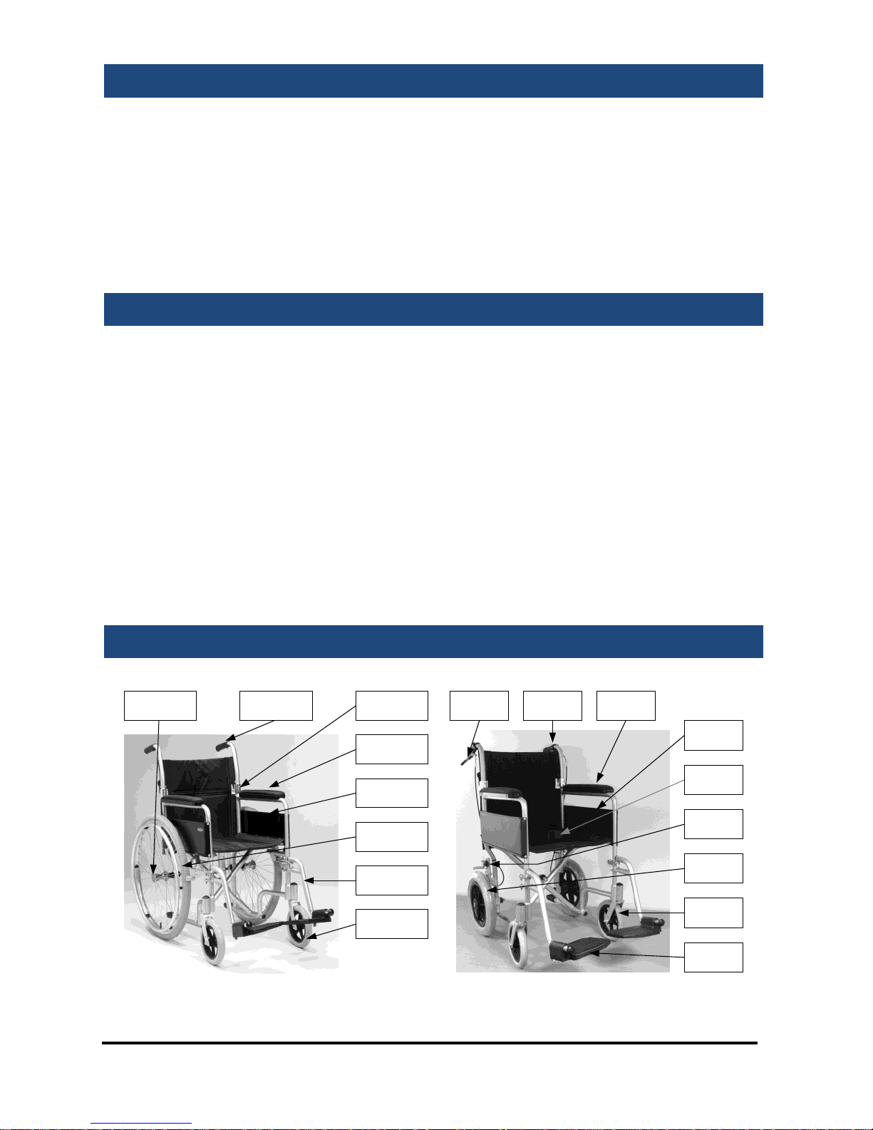
Parts Description
Self Propel (LAWC001)
Transit (LAWC002)
LEG REST
PUSH HANDLE
QUICK
RELEASE PIN
1/2 FOLD BACK
MECHANISM
ARM REST
SIDE PANELS
24" WHEEL &
HANDRIM
FRONT
CASTOR
FRONT
CASTOR
PUSH
HANDLE
BRAKE
LEVER
ARM
REST
SIDE
PANEL
LAP BELT
BRAKE
12.5"
WHEEL
LEG
REST
Page 3
Lightweight Aluminium Wheelchair
Page 3 of 12
Leg rest Adjustment
For optimum comfort it is important to attain the correct leg position. The
footrests have been designed so that they can be extended into one of 5
fixed positions. Unscrew the black knob on the back of the silver tubing.
Adjust the legrest as required then reattach the black knob to secure.
To install the leg rests, place the leg rest
brackets on the pins at the side of the
wheelchair frame (as shown by “1”) then swing
in the leg rest (“2”) until it locks in position.
Leg rests will swing in or out to reduce the
length of the wheelchair. Push chrome lever
whilst rotating the leg rest. To remove, simply
pull up on the leg rest when swung out.
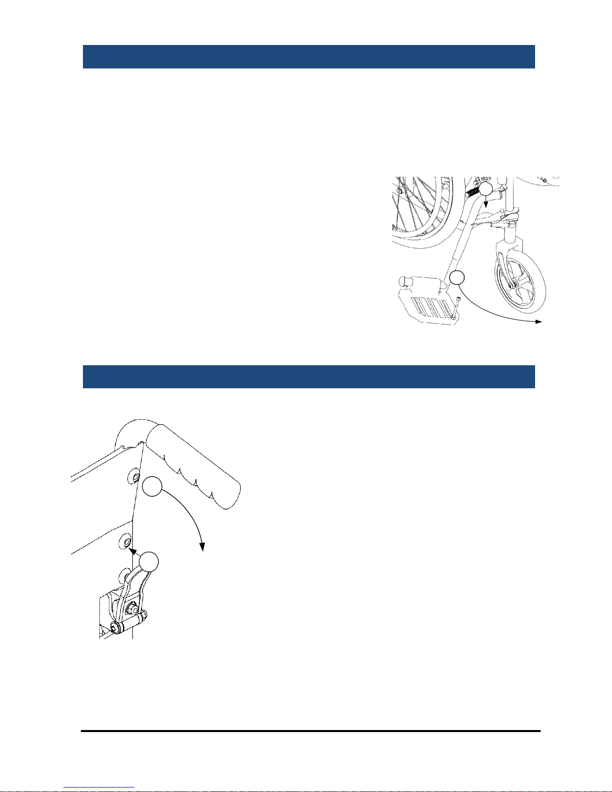
Folding Back Mechanism
Push the black paddle towards the back post
with your thumb (1) whilst pulling the handle
down (2), as shown. Repeat this operation for
the other handle. To put the backrest back
into position, lift both handles together and
the folding mechanism will lock back
automatically.
Do not push down on the handles to raise
the front of the wheelchair, as this could
result in damage to the wheelchair. Use the
stepper tube as described later in the
handbook.
1
2
2
1
Page 4

Lightweight Aluminium Wheelchair
Page 4 of 12
Disassembly And Storage
This wheelchair has a number of quick release components and the
wheelchair frame is easily foldable to facilitate a light carry weight
and minimize storage space.
1.
Quick Release Wheel.
On the self propel model, the rear wheels can be removed. To remove
the rear wheel, push the button in the centre of the wheel hub and
slide the wheel from its axle.
2.
Half Folding Back. Follow the previous instructions to fold the
back.
3.
Leg Rests. Follow the previous instructions to remove or swing
out the leg rests.
4.
Folding the wheelchair.
Grab the centre of the front and rear edges of the seat sling. Pull
upwards on the seat sling and the wheelchair should naturally fold up.
IMPORTANT: The wheelchair has not been tested as a seat in a
motor vehicle. Users should always transfer to the vehicle’s seat and
the wheelchair should be safely stowed away.
Page 5

Lightweight Aluminium Wheelchair
Page 5 of 12
Using The Stepper Tube
An attendant can use the stepper tube to raise the front castors (when
mounting a kerb for example). To use, push down on the stepper tube with
a foot. Do not raise the front castors by pushing down on the push handles
as this could result in damage to the wheelchair.
To mount a kerb. Approach the kerb head on. Then the attendant uses the
stepper tube to raise the front castors, and lowers the front castors on the
raised kerb. Finally the attendant should push the wheelchair forward,
lifting it up slightly to mount the kerb if required.
To go down a kerb. Line up the front castors with the edge of the kerb.
The attendant uses the stepper tube to raise the front castors and tip the
user slightly back. Keeping the castors raised, slowly lower the wheelchair
down the kerb.
Brake Operation
Parking Brakes
To apply the parking brakes, push the handle on the brake unit until
locked in place. To release the brake, push the handle in the opposite
direction. The brakes should always be applied when the wheelchair is
stationary.
Cable Brakes
On the transit model, the attendant
pushing the wheelchair may use
cable-operated brakes to slow the
wheelchair. To apply the brakes,
squeeze the large lever (A) on the
push handles and the brakes will be
applied. Release the levers to
remove the brake.
When stationary, apply the parking
brakes as described above.
Page 6

Lightweight Aluminium Wheelchair
Page 6 of 12
Operation And Propulsion
Before Using the Wheelchair read the safety notices below:
!
Use slow speeds on gradients. Do not exceed the
maximum gradient stated.
The wheelchair is only suitable for single occupancy.
Keep your feet on the footplates when moving. Do not
stand on the footplates.
Do not use escalators.
Do not reverse down a gradient
Maintain proper balance at all times. Users should not
move their centre of gravity out of the seating area.
Do not reach for items further than your arm will
extend.
Be aware of hazards in your environment, such as
narrow doorways, steps, household appliances,
children’s toys, etc.
We recommend you consult your healthcare
professional for advice about transferring to and from
the wheelchair. The parking brakes should always be
applied when transferring.
Ensure that fingers and objects do not get caught in the
spokes of the rear wheels.
The transit wheelchair can only be propelled by an attendant. The
attendant should push the wheelchair from behind using the handgrips,
and following the safety advice above.
The self propel wheelchair can be propelled by an attendant (as directed
above) or the wheelchair user. The user can propel themselves by pushing
on the handrims attached to the side of the rear wheels, and slow
themselves down by applying pressure to the handrims.
When stationary the brakes should always be applied.
Page 7

Lightweight Aluminium Wheelchair
Page 7 of 12
Using The Lap Belt
The lap belt is to restrain the wheelchair occupant during normal use. The
lap belt is not be used as a seat belt in a motor vehicle. Under no
circumstances should the Travel Chair be used as a seat in a motor
vehicle (e.g. cars, buses, trains, etc). The lap belt comes as standard with
the LAWC002. It is available as an option on the LAWC001.
The lap belt should be adjusted to suit each user. The length of the belt
can be adjusted by the tri-glides (as shown in the diagram overleaf). The
lap belt has a luggage-style large locking clip to fasten and unfasten the
lap belt. To fasten the lap belt, push the clip in to the receiver until it locks
in the position (which can be heard by an audible click).
When fastened, the lap belt should be tight around the user’s pelvis
without causing discomfort or undue pressure. This will help keep the
user’s hips and pelvis towards the back of the wheelchair. Use the triglides (shown) to adjust the length of the lap belt. The length of the lap
belt should be checked each time the belt is used.
There is a risk of suffocation from users ‘submarining’ (where they slide
down the chair until the lap belt is around the neck area). To reduce the
risk of this, ensure that the lap belt is used under supervision and is used
as instructed.
The lap belt may not be suitable for all users of wheelchairs. Seek
professional medical advice before using the lap belt.
Page 8

Lightweight Aluminium Wheelchair
Page 8 of 12
Care And Maintenance
Before each use of the wheelchair, the brakes and tyres should be
checked.
The wheelchair should be stored in a dry environment, away from
direct sunlight. When in storage the wheelchair can be folded up
The wheelchair should be kept clean and dust free. This can be done
with a duster or damp cloth.
The user should routinely check the following items. It is recommended
that a Drive DeVilbiss dealer services the wheelchair annually, where
these items should be repaired, replaced, adjusted and/or lubricated if
required:
Tyre wear
Wheel bearings
Castors
Brakes
Legrest locking
mechanism
Seat upholstery
Back upholstery
Arm pads
Rear wheel quick release pin
Half folding back mechanism
Back posts
Wheelchair (folds up)
Page 9

Lightweight Aluminium Wheelchair
Page 9 of 12
Powerpack Installation
This wheelchair is suitable for some retrofit
powerpacks, such as the PowerStroll. A
suggested configuration is shown left.
Note this is a suggestion, and the mounting
position will need adapting to be suitable for
the user and the powerpack used. For more
information about the PowerStroll contact
your Drive DeVilbiss dealer or visit
www.drivedevilbiss.co.uk for more details.
LAWC001
LAWC002
Dimensions *1
(L x W x H)
106 x 61 x 90cm
41¾” x 24” x 35½”
96 x 55 x 91cm
38” x 21
¾
”
x
36”
Dimensions *2
(L x W x H)
71 x 24 x 70cm
28” x
9
½
”
x 27½”
66 x 29 x 74cm
26” x
11
½
”
x
29”
Seat
(W x D x H)
46 x 40 x 48cm
18” x 15¾” x 19”
46 x 40 x 48cm
18” x 15¾” x 19”
Wheel Spacing
43cm / 17”
43cm / 17”
Weight * 1
14.5kg / 31.9lb
12.4kg / 27.3lb
Weight * 2
8.5kg / 18.7lb
11kg / 22lb
Max User Mass
115kg / 18 stone
115kg / 18 stone
Max Gradient
10º
10º
Dimensions * 1 refers the wheelchair assembled
Dimensions *2 refers to the wheelchair folded and parts removed
Weight *1 is the total weight.
Weight *2 is the weight without removable components
We reserve the right to change designs and specifications.
Page 10

Lightweight Aluminium Wheelchair
Page 10 of 12
Warranty
Your Drive DeVilbiss branded product is warranted to be free of defects in
materials and workmanship for one year from date of purchase. This
device was built to exacting standards and carefully inspected prior to
shipment. This warranty is an expression of our confidence in the
materials and workmanship of our products and our assurance to the
customer.
In the event of a defect covered by this warranty, we will at our option
supply parts or replace the device. This warranty does not cover device
failure due to owner misuse or negligence, or normal wear and tear. The
warranty does not extend to non-durable components, such as rubber
accessories, castors and grips, which are subject to normal wear and need
periodic replacement. The wheelchair frame has a 5-year warranty.
If you have any queries or require full warranty conditions, please contact
your Drive DeVilbiss stockist.
Drive Germany: Drive UK:
Drive Medical GmbH & Co. KG
Leutkircher StraBe 44
D-88316 lsny/Allgau (Germany)
Drive DeVilbiss Healthcare Ltd
Heathfield lane, Birkenshaw
West Yorkshire BD11 2HW
Web www.drivemedical.de
Web
www.drivedevilbiss.co.uk
Page 11

Lightweight Aluminium Wheelchair
Page 11 of 12
Spare parts available
The following spare parts are available for your wheelchair:
Z16130-01: RHS cross brace
Z16140-01: LHS cross brace
Z16210-01: Seat canvas
Z16260-01: Back canvas
Z16325-01: Push handle (Self Propel)
Z16330-01: Push handle (Transit)
Z16350-01: Half fold mechanism
Z16410-01:
Castor
wheel
and
fork
Z16451-01: Quick release pin for 24” wheel
Z16460-01: 24” rear wheel
Z17480-01: 12.5” rear wheel
Z10592-01VY: Arm pad
Z17593-01: Side panel
Z16600-01: LHS leg rest
Z16650-01: RHS leg rest
Z16700-01: RHS brake (for 24” wheel)
Z16750-01: LHS brake (for 24” wheel)
EB004: Brake set (for 12.5” wheel)
Z16425-01: Rear Wheel Hub Cap (LAWC002) Z15427-01: Castor Housing Cap
The parts are available exclusively from Drive DeVilbiss stockists. To order
the parts please visit the stockist where you bought the wheelchair or visit
www.drivedevilbiss.co.uk to find your local stockist.
Spare part catalogues and other documentation can also be found at
www.drivedevilbiss.co.uk/technical-support
Page 12

The Team at Drive DeVilbiss
develops its products to give
our customers the freedom to live
independently. This encompasses
their daily home life and provides
them with the opportunity to enjoy
an outing with family and friends.
Our goal is to develop a range that
will provide individuals with a
chance to enjoy every day life.
Drive DeVilbiss Healthcare Ltd, Heathfield Lane,
Birkenshaw, West Yorkshire, BD11 2HW
Tel: 0845 0600 333
Fax: 0845 0600 334
Email: info@drivedevilbiss.co.uk
www.drivedevilbiss.co.uk
Dealer Stamp
 Loading...