

Page 1
Instruction Manual
AGF-6X2 Digital EMS
Drive DeVilbiss Healthcare
99 Seaview Boulevard
Port Washington, NY 11050
Tel: 877- 224-0946
www.drivemedical.com
REV 1.03.29.17
Page 2

1
INDEX
1. Introduction .......................................................... 2
2. Caut ions ................................................................ 3
3. War nings ............................................................... 4
4. Contr aindic atio ns ................................................ 4
5. Advers e React ions .............................................. 4
6. Gener al Descript ion ............................................. 5
7. Constructi on ......................................................... 6
8. Technical Specif icatio ns ...................................... 8
9. Replaceme nt Parts .............................................. 10
10. Ac cesso r ies ......................................................... 10
11. G raphic Sy mbols .................................................. 11
12. Op erat ing Instructions ........................................ 12
13. Att achment o f E lectrode Lead Wires ................. 12
14. Lea d Wire Maint enance ....................................... 13
15. E lectr ode Options ................................................ 13
16. E lectr ode Placement ........................................... 13
17. T ips f or Skin Care ................................................ 14
18. Applic ation of Reusable self adhes ive
ele ct rodes ............................................................ 15
19. Adjust ing the Contro ls ........................................ 16
20. Ba tter y Inform ation .............................................. 22
21. M aintenanc e, Transportat ion, and Storage of
TENS Device.......................................................... 24
22. S afety- Technical Contr ols ................................... 24
23. M alf unctions ......................................................... 25
24. C onformity to Sa fety Standar ds ......................... 25
25. W arranty ................................................................ 26
Manuf act urer ........................................................ 26
26. Ap pendix ............................................................... 27
Chapter Contents Page
Page 3

32
C
hapter 1 : INTRODUCTION
EXPLANATION OF EMS
Elec tri cal Musc le Sti mula tion is a n inter nationally acc epted and
pro ven wa y of t reat ing mu sc ul ar injur ies . I t w ork s b y sendin g
electroni c pulses to the muscle needing treatment; this causes th e
mus cle to exerci se pass ively.
It is a product derived from the squ are waveform, origi nally invented
by Joh n Farad ay in 18 31. Th rough the squar e wave pat tern it is
able
to work directly on muscle motor neurons. The AGF-6X2 Digital
EMS has l ow fr eque ncy and th is in c onjunction wi th the square
wave p att ern allow s d ir
ect work o n mu sc le g roupings . T his is
being widely us ed in hosp itals and s ports clin ics for the treatment
of mu scular injuries and for the r e-educati on of paralyzed musc les,
to pr event atr ophy in aff ected muscl es an d improving mu scl e tone
and bl ood c ircu lation.
HOW EMS WORKS
1. Relaxati on of mus cle spas ms
2. Preven tion or retar dation of dis use atrop hy
3. Incr easing local blood circ ulation
4. Mus cle re-ed ucat ion
5. Immediat e pos t-sur gical s timul ation of c alf muscl es to prevent
venous thr ombos is
6. Maintaining or i ncreasi ng r ange of motion
The EMS un its s end comf ortable impul ses th roug h the s kin th at
st imul ate t he n erves i n t he t reatme nt area. W hen th e mus cle
receives this si gnal it contrac ts as i f the brai n has s ent the s ignal
its elf . A s the
sig nal s tren gth in cre ases , t he musc le f lexes as in
physical exercise. T hen when the pulse ceases, the mus cle relaxes
and t he c ycl e st arts over agai n, ( St im ulat ion , C ont rac tio n and
Relaxation.) Powered muscle stimulators should only be us ed under
medi cal s upervi sio n fo r adj unc tive ther apy f or th e tre atmen t of
medical diseas es and c onditions .
I
MPORTANT SAFETY INFORMATION!
Read instruction manual bef ore operation. Be s ure to comply with
all “CAUT IONS” and “W ARNINGS” i n the manual. Failure to f ollow
instructions ca n c aus e har m to us er or device.
Chapter 2: CAUTIONS
1. Federal law (USA) rest rict s t his devic e t o s ale by or on the
order of a physic ian
2. Safety of powered muscle s timulators for use during pregnancy
has not b een establi shed.
3. Caution should be used for patients with suspected or diagnosed
heart problem s.
4. Caution should be used for patients with suspected or diagnosed
epile psy .
5. Cauti on s hould be used in the pre senc e of the following:
a. Wh en t here is a ten dency to hemorrh age f ollowing ac ute
traum a or f racture;
b. Followin g r ecent s ur
gica l p roc edures wh en musc l
e
cont racti on m ay di srupt the healin g pr oces s;
c. Over the menst ruatin g or pregnan t uterus ; and
d. Over ar eas of the skin which lack normal s ensation.
6. Some p atients may experi ence skin irritation or hypers ensi tivity
due to th e electri cal s timulation or electric al cond uctive medium.
The irritation can usually be redu ced by usi ng an altern ate
conduc tive medium, o r alt ernate elect rode p lacemen t.
7. Elect rode plac ement and s timulat ion s etting s s houl
d be b ased
on th e gui dance of the p rescr ibing practi tion
er.
8. Powered muscl e st imul ators shoul d be kept out of the r each of
child ren.
9. Powered mu scle stimulat ors should b e used only with the leads
and electr odes recommen ded for use by the m anuf actur er.
10.Port able p owered muscl e s timul ators shou ld not be used while
driving , operating mac hiner y, or duri ng any ac tivity in which
involunt ary muscle c ontr action s m ay put the user at undue
risk of injury .
Page 4

54
C
hapter 3 : WARNINGS
1. The long-term effec ts of c hron ic el ectri cal stimu lation are
un kno wn.
2. Stimulat ion sh ould n ot be applied over t he carotid sinus nerves,
parti cular ly i n pat ients wit h a known sens itivity to the carotid
sinu s ref lex.
3. Stimulation shoul d not be applied over the neck or mouth. Severe
spasm of t he laryngeal and ph aryngeal muscles may occ ur and
the contr acti ons may be str ong enough to clos e t he ai rway or
cause diff iculty in breat hing.
4. Stimulation should not b e applied tran sthor acically in that t
he
introduction of elect
rical c urrent int o the heart may cause card iac
arrh ythmia s.
5. Stimulation should not be applied transcer ebrally.
6. Stimulatio n s hould not be appl ied over swollen, i nfec ted, or
inflamed areas or sk in eruptions, e.g., phlebitis, t hrombophlebitis,
varic ose vein s, etc .
7. Stimulati on s hould n ot be applied over, or in proximity to,
canc erou s lesi ons .
Chapter4: CONTRAINDICATION
Powered mus cle sti mulat ors sh ould not be used on patients wit h
card iac demand pacem akers.
Chapter 5: ADVERSE REACTIONS
Skin irrit ation and burns b eneath the elec trodes h ave been reported
with the use of powered mu scle stimulators. If skin irritat ion occu rs,
disc onti nue use and c ons ult your ph ysic ian.
Chapter 6: GENERAL DESCRIPTION
The EMS is a battery oper ated puls e generator
that sends elect ric al impu lses throu gh electrodes to the body and
reac hes the u nder lyi ng n erves or mus cl e gro up. T he d evic e is
provided with two c ontrollab le output channe ls, each indepen dent
of each other. An electrod e pair can b e c onnec ted to eac h ou tput
chan nel.
The
elec tro nic s of th e EMS c reate elec tri cal
impul ses whos e In tens ity, Pulse W idth, Puls e Rate, Contr acti on,
Relaxation an d Ramp ma y b e alter ed wit h the sw itc hes. Pr es
s
bu
tt ons a r e ve ry ea sy to us e and th e pan el c ove r p reven ts
accident al c hanges in the s etting.
.
AGF-6X2 Digital
AGF-6X2 Digital
Page 5
76
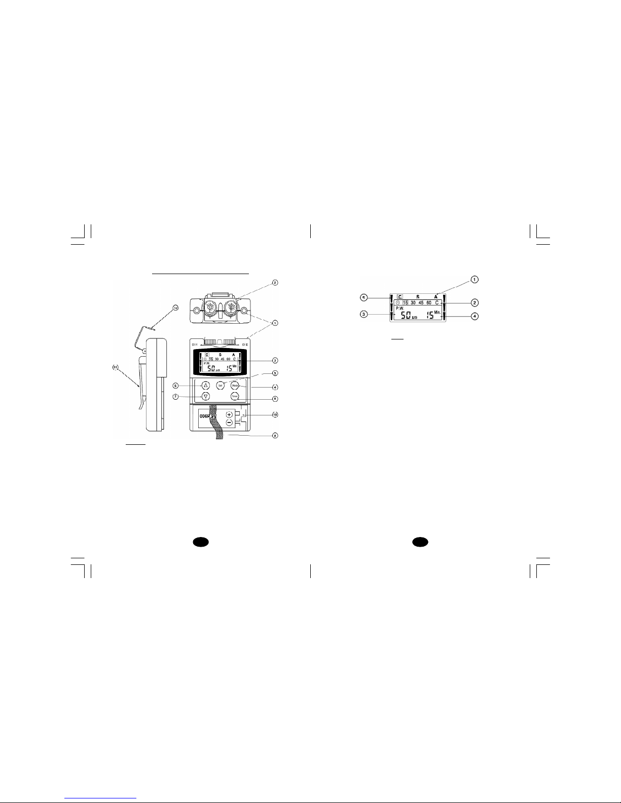
FRONT
(1) LEAD CONNECTOR
(2) INTENSITY CONTROL ( ON/OFF SWITCH)
(3) LIQUID CRYSTAL DISPLAY
(4) MODE CONTROL
(5) SET CONTROL
(6) INCREMENT CONTROL
(7) DECREMENT CONTROL
(8) TIMER CONTROL
(9) BATTERY STRIP
(10)BATTERY COMPARTMENT
(11) BELT CLIP
(12)PROTECTIVE COVER
Chapter 7 : CONSTRUCTION
LCD
(1) MODE
(2) TIMER
(3) PULSE WIDTH / RATE
(4) RAMP / ON / OFF TIMER
(5) OUTPUT INDICATOR
Page 6
98
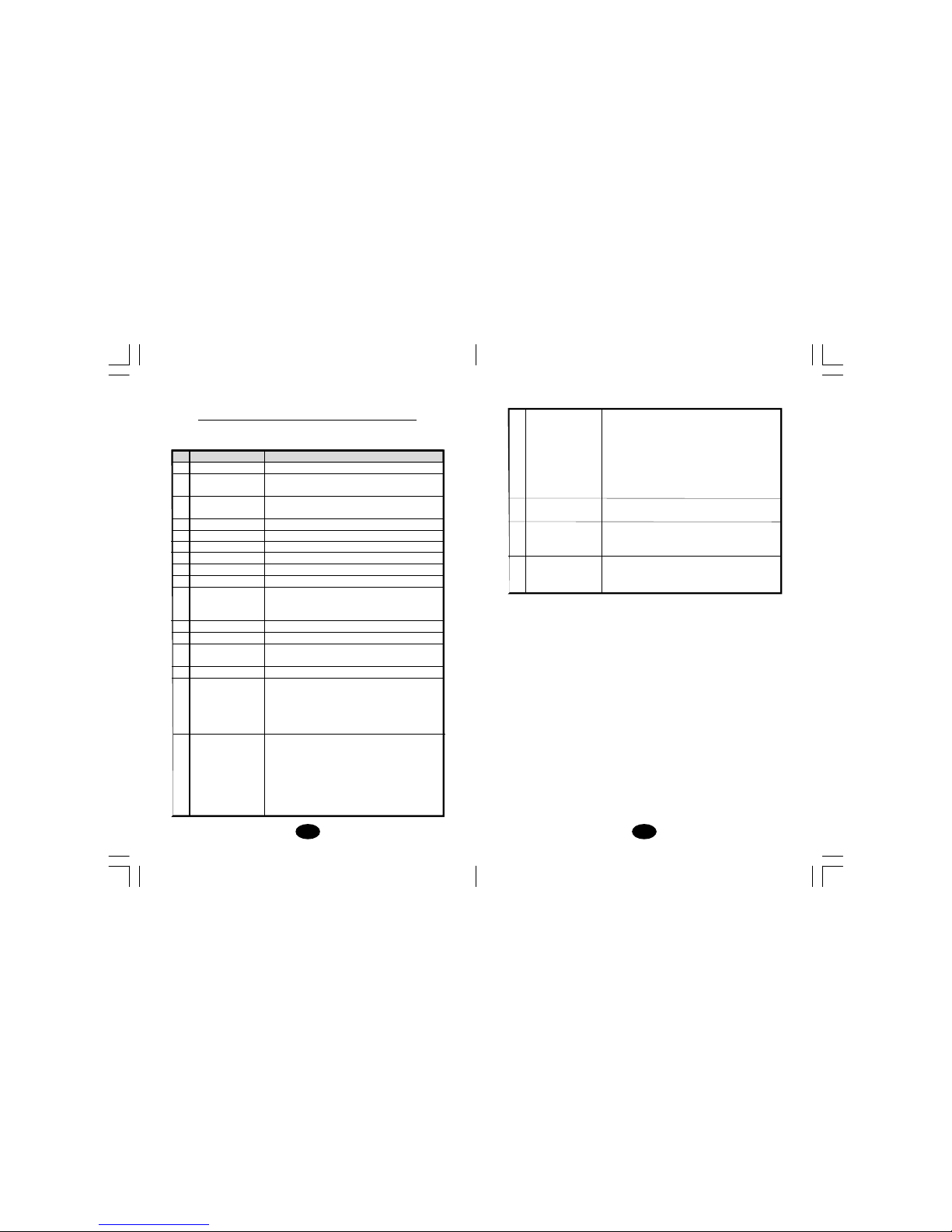
17 A lte rn ate( A) The s timulation of the CH2 will occur after
the 1st c ontraction of CH1 is c ompleted. In
this m ode, the s etting of ON T ime should
be no less than two ti mes of t he “Ramp”
time. The OFF Time should be equal or more
than the ON T ime.
ON TIME ≥Ramp up + R amp down
OFF TIME ≥ON TIME
18
Compl ianc e Met er
The ac cumu lated t reatment tim e can be
recorded. Total recorded time is 999 hours.
19 O peratin g Temperature:0°~40°C
Condition Relative Humidty:30%~ 75%
Atmosph ere Pres sure : 700H pa~1060H pa
20 Toleranc e There may be a +/-10% t ol
eranc e of all
setti ngs and +/- 20 % t oleranc e of outp ut
of intens ity.
Chapter 8 : T ECHNICAL SPECIFICATIONS
The technical specifi cation details of
EMS
are as foll ows:
MECHANISM TECHNICAL DESCRIPTION
01 C hannel Dual, isolat ed between chann els
02 P ulse Amplitud e Adjust able 0- 100 mA into 5 00 ohm load
each channel .
03 O utput Voltage Adjust able 0-50 V, Max outp ut 50 V peak to
peak in to 50 0ohm load eac h c hannel.
04 W ave Form Asymmet ric al r ectang ular biphasic pul se.
05 P ower Su ppl y One 9 Volt Battery, t ype 6 F22
06 S ize 10.1cm( L) x 6.4cm(W ) x 2.5cm( H)
07 W eight 140 grams (batt ery i nclu ded)
08 On Time Adju stable, 2~90
secon ds , 1 Sec./ st ep
09 O ff Time Adju stable, 0~90 secon ds , 1 Sec./ s tep
10 Ramp Time Adjustable, 1~8 second s, 1 Sec ./ step, T he
“On” time will increas e and decrease in
the setti ng value.
11 P ulse Rate Adjus table, 2~150 H z , 1Hz / step
12 Pu lse Width Adjus table, 50~300µs , 10 µs / st ep
13 T imer Adju stable, 15, 30 , 45, 60 minu tes or
Continue.
14 O utput Mode Cons tant ,Synch ronou s, A lter nate
15 C onstant (C) C onstant sti mulation bas ed on setting
value. Only pulse width , pulse rate and
timer ar e adj
ustable in this mode.
“Const ant” is equal t o the “N ormal” mode
of a TENS uni
t.
16 S ync hron ous (S ) St imulati on of bot h c hannels occu rs
synchronous ly. The “ ON” time i ncluding
“Ramp U p” and “R amp Down” t ime.
Theref ore, th e sett ing of ON T ime s hould
be no less than two ti mes of t he “Ramp”
time in this mode.
ON TIME ≥ Ramp up + Ramp down
AGF-6X2 Digital
Page 7

1110
C
hapter 11 :GRAPHIC SYMBOLS
1. Note Oper ating Instru ction s
2. Degree of Elect rical Protection BF
3. Do not insert the plu g in to AC power supp ly s oc
ket.
4. Timer
5. Consult Operation Instr uction s
6. Manufac tur er
7. Serial Number
8. DC Cur rent(D C P ower s ource)
9. Increment
10. Decrement
Chapter 9 : REPLACABLE PARTS
The repl aceable parts and acc essori es of EMS
devices are as given b elow –Exc ept leads , el ectrod es, battery and
batter y ca se cover, please do not tr y to replac e the oth er parts of
a d evic e.
PARTS
01 ELECTRODES LEADS
02 ELECTRODES
03 9V BATTERY ,TYPE 6F22
04 BELT CLIP
05 BATTERY CASE COVER
06 LEADCONNECTOR
07 MAINPCB
08 INTENSITY KNOB
09 LCD COVER
10 INTENSITYCONTROLCOVER
Chapter 10 :ACCESSORIES
Eac h EMS c ome s c omp let e wi th s tan dar d
acc ess ories and th e standa rd labels as given belo w:
I. Ac ces sori es
REF. NO. DESCRIPTION Q’TY
1. KF404 0 40 X 40 mm Adh esive Electrodes 4 pieces
2. KB-24 Elec trodes Lea ds 2 pieces
3. GC-01 9 V Batter y, type 6F2 2 1piec e
4. Instru ction Manual 1 piece
5. Carryin g C ase 1 piece
AGF-6X2 Digital
AGF-6X2 Digital
Page 8

1312
After connecting the wires to the stimulator, attach each wire to
an electrode. Use care when you plug and unplug the wires.
Jerking the wire instead of holding the insulated connector body
may cause wire breakage.
CAUTION
Do not insert the plug of the patient lead wire into any AC power
supply socket.
Chapter 14: LEAD WIRE MAINTENANCE
Clean the wires by wiping with a damp cloth. Coating them lightly
with talcum powder will reduce tangling and prolong life.
Chapter 15 : ELECTRODE OPTIONS
The electrodes are disposable and should be routinely replaced
when they start to lose their adhesive nature. If you are unsure of
your electrode adhesive properties, order replacement electrodes.
Replacement electrodes should be re-ordered through or on the
advice of your physician to ensure proper quality. Follow application
procedures outlined in electrode packing, to maintain optimal
stimulation and to prevent skin irritation.
Chapter 16: ELECTRODE PLACEMENT
The placement of electrodes can be one of the most important
parameters in achieving success with EMS therapy. Of utmost
importance is the willingness of the physician to try the various
styles of electrode placement to find which method best fits the
needs of the individual patient.
Every patient responds to electrical stimulation differently and their
needs may vary from the conventional settings suggested here. If
Chapter 12: OPERATING INSTRUCTIONS
1) Insert the 9V battery into the device’s battery compartment.
Make sure to remove the plastic seal on the 9V battery. Line up
the positive and negative terminals on the battery with their
corresponding terminals in the device. Make sure that both
Intensity control (ON/OFF Switch) knobs are in the off position.
2) Insert the lead wires into the lead wire sockets on top of the
device.
3) Open the electrode package. Then insert each lead wire pin
into the pig tail of the electrodes
4) Place the electrode on your body as directed by your physician.
5) Slowly turn on the device by rotating the Intensity control
(ON /OFF Switch) knobs.
6) Select the mode and settings as directed by your physician.
7) Slowly increase or decrease the intensity as directed by your
physician by rotating the Intensity control (ON/OFF Switch)
clockwise to increase, counter clockwise to decrease.
8) After Treatment, Turn the device off by rotating the Intensity
control (ON/OFF Switch) counter clockwise to the zero setting.
Chapter 13 : ATTACHMENT OF ELECTRODE
LEAD WIRES
The wires provided with the system insert into the jack sockets
located on top of the device. Holding the insulated portion of the
connector, push the plug end of the wire into one of the jacks (see
drawing); one or two sets of wires may be used.
Page 9

1514
C
hapter 18: APPLICATION OF RE-USABLE SELF
ADHESIVE ELECTRODES
Appl icat ion
1. Clean and dry th e s kin at th e p resc ribed area thoroughl y with
soap and water prior to appli cation of elect rodes .
2. Ins ert the lead wire into the pin connect or on the pre-wi red
electr odes.
3. Remove the el ectrod es f rom the prot ective liner and apply the
electrod es firml y to the treatment sit e.
R
emo val
1. Lift at t he edg e of elect rodes and peel; do not pull on the lead
wires bec ause it may damage the electr odes.
2. Plac e the electro des on th e li ner and remove th e lead wire by
twisting an d pulling at the same time.
C
are an d Sto rag e
1. Between uses , store the electr odes in the r esealed bag in a
cool dr y p lac e.
2. It may be helpful to impr ove repeated application b y spreading a
few d rops of c old water over the adh esive an d t urn the s urfac e
up to air dry. Over Saturation with water will redu ce the adhes ive
prop erti es.
the init ial res ults ar e not pos itive, speak to your phys ician about
alternative stimul ation s ettings and/or electr ode plac ements. Once
an ac ceptabl e plac ement has bee n ac hieved , ma rk dow n the
electrodes s ites and the s ettings, so the patien t
can easily c onti nue
treatment at home.
Chapter 17: TIPS FOR SKIN CARE
To avoid s kin irritation, especial ly if you have sensitive skin, fol low
thes e s ugg esti ons:
1. W ash t he ar ea of s kin where you will be pl acing th e elect rodes,
using mild s oap and water before applying elec trodes, and aft er
taki ng the m off. Be sure to ri nse soa p off thorou ghl y an d dry sk in well.
2.
Exces s hai r may be clipped with sc issors; do n ot shav e stimu lation area.
3. W ipe the ar ea with the ski n p reparat ion your physician has
recom mended. Let this dry. Appl y elec trod es as direc ted.
4. Many skin problems ar
ise fr om the “pulling stress” from adhesive
patches t hat are exc essively stret ched ac ross th e s kin duri ng
applicat ion. To prevent this, apply electrod es from center
outward; avoid str etch ing over the skin.
5. To minimize “pulling stress ”, t ape extra lengths of lead wires to
the s kin in a loop to prevent tugging on electr odes.
6. W hen removing elect rodes, always remove b y pu lling in t he
directionof h air growth .
7. It may be helpful to rub skin l otion on electrode plac ement ar ea
when not w eari ng elec trodes .
8. N ever apply e
lectr odes over irritated or br oken sk in.
Page 10

1716
To reduce the current strength or switch the device off, turn the
control counter clockwise to the required setting or off-position,
respectively.
The controls are protected by a cap to avoid unintentional change
of intensity.
3. Lead Connector
Connection of the electrodes is made with the two-lead connector
(lead wires). The device must be switched off before connecting
the cables. Both intensity controls must be at the Off position.
Electrodes must be pressed firmly on the skin.
4. Mode Control
There are 3 modes available – Constant, Synchronous and
Alternate. A mode can be selected by pressing the “Mode”
control.
Important
1. Do not apply to broken skin.
2. The electrodes should be discarded and re-ordered from your
physician when they are no longer adhering.
3. The electrodes are intended for single patient use only.
4. If irritation occurs, discontinue use and consult your physician.
5. Read the instructions for use of self-adhesive electrodes before
application.
Chapter 19 : ADJUSTING THE CONTROLS
1. Slide-on Cover:
A slide-on panel cover covers the controls for selecting mode
and adjusting settings. Your medical professional may wish to
set these controls for you and request that you leave the cover
in place.
2. Power On/Off Switch and Intensity Controls:
If both controls are in the off-position, the device is switched off.
By turning the controls clockwise, the appropriate channel is
switched on and the indicator of power (CH1 or CH2) will reveal
on the LCD.
The current strength of the impulses transmitted to the electrodes
increases further when the control is turned clockwise.
Page 11

1918
9. Steps to Set a New Program
The settings can be adjusted according to the following steps.
a.Turn on the Intensity
After the electrodes are placed firmly on skin and the lead
wires are plugged in the socket of device, turn the on/off
control clockwise. The menu will reveal on LCD. Notice the
indication of power and function on the LCD.
b.Select Mode
Select a mode by pressing the “Mode” control. The mode you
selected will show up on the top of liquid crystal display.
When “ Constant” mode is selected, you can set only pulse
width, pulse rate and timer later on. All parameters are
adjustable on the Synchronous and Alternate mode.
After a mode is selected, press “SET” control to enter next
setting. You may adjust the setting only when the value is
flashing. Then press the “Increment” or “Decrement” control
to change the settings. Repeat the same procedure until all
settings are adjusted. The program will be stored automatically
after created.
c. Set Pulse Width
The pulse width determines the length of time. Each electrical
signal is applied through the skin, which controls the strength
and sensation of the stimulation. Press “SET” control to enter
this setting after “Off” time is adjusted. The pulse width is
adjustable from 50 to 300 µs. Press the increment or decrement
controls to adjust the setting.
d. Set Pulse Rate
The pulse rate determines how many electrical impulses are
applied through the skin each second. Press “SET” to enter this
5. Set Control
By pressing the “Set” control, you may enter the setting you
intend to make adjustment. You may start to set the value by
pressing the “ Increment” and “ Decrement” controls when the
value is flashing.
6. Increment Control
This button controls the increase of settings. When pressing
this button, the parameter will increase. Press the button until
the value desired is reached.
7. Decrement Control
This button controls the decrease of parameter. When pressing
this button, the parameter will decrease. Press the button until
the value desired is reached.
8. Timer
The treatment time can be selected by pressing the “Timer”
control. There are five settings available, 15, 30, 45, 60 minutes
and continue. Press the “Timer” control to select a setting
needed. The output of unit will be shut off when time is up.
Page 12

2120
In Alternate mode, the OFF Time should be equal or more than
the ON Time. (OFF TIME ≥ ON TIME)
h. Set Timer
The treatment time can be selected by pressing the “Timer”
control. There are five settings available, 15, 30, 45, 60 minutes
and continue. Press the “Timer” control to select a setting
needed. The treatment time will countdown automatically one
minute by one minute. Its output will be shut off when time is up.
Treatment Time countdown
The treatment time will countdown automatically one minute
by one minute. Its output will be shut off when time is up.
12. Patient Compliance Meter
The accumulated treatment time can be checked and deleted by
the following steps. Total recorded time is 999 hours.
Check & Delete Accumulative Record
Press “Mode” control and turn on the power simultaneously.
The LCD will show the accumulated operation time. Press “Timer”
control and the record will be deleted followed by a beeper sound.
RESET
menu. By pressing the increment and decrement controls, the
number of current impulses per second (Hz) for both channels
can be continually adjusted. The pulse rate is adjustable from 2
Hz to 150 Hz.
e. Set Ramp Time
The ramp time controls the time of output current that increase
from 0 to the setting level, and from the setting value to 0. When
the ramp time is set, each contraction may be ramped up and
down in order that the signals come on and come off gradually
and smoothly. The ramp time is adjustable from 1 to 8 seconds.
f. Set On Time
The On Time controls the time of stimulation. By pressing the
“Set” control, the contraction time can be adjusted. Both
channels’ stimulation is cycled on and off by the contraction
and relaxation settings. The range is adjustable from 2 seconds
to 90 seconds.
As the “ON” time including the ramp up and ramp down time, the
setting of it should be no less than two times of the “Ramp” time.
(ON TIME ≥ Ramp up + Ramp down)
g. Set Off Time
The Off Time controls the time of relaxation. By pressing the
“SET” control, the relaxation time can be adjusted. Both channels’
stimulation is cycled on and off by the contraction and relaxation
settings. The range is adjustable from 0 to 90 seconds.
Page 13

2322
BATTERYCHARGING
(1) Plug th e c harger into any working 110 or 220/240v mains
electric al outlet. The use of a ny att achment not supplied with
the c harg er may result in the r isk of f ire, electric shoc k, or
injury to per sons .
(2) Follow the battery manufacturer’s i nstructions for charging time.
(3) After the batt ery man ufac ture r’s r ecommend ed c harging tim e
has been completed, unplug the charger and remove the battery.
(4) Batter ies sh ould always be s tored in a f ully c harg ed state.
To ensu re optimum battery perfor mance, follo w t hese
guidelines:
(a) Although over
charging the batt eries for up to 24 hours will
not dam age t hem, repeated overc harging may de creas e
usef ul battery lif e.
(b) Always store batt eries in their charged c onditi on. After a
battery has b een disc harged , recharge it as s oon as
possibl e.If the b attery is st ored more th an 60 days, it may
need to be rec harged.
(c )Do not short t he terminals of the battery. This will caus e the
battery to get hot and can cause permanent dam age. Avoid
stor ing the batteri es in your p ocket or purse where the
termin als may acc id
entally come into contac t with c oins,
keys or an y met al objects .
(d)W ARNINGS:
1.Do not attempt t o c harge any other t ypes of bat teri es in
your ch arger, other t han r echarg eable batteries mad e f or
your c harger . Other types of batter ies may leak or burst.
2.Do not in cinerate the rechargeabl e bat tery as i t may
explode!
10.Check/ Replac e th e B attery:
Over t ime, in or der to ens ure the f unct ional
safet y of T ENS,
chang ing th e bat tery is nec essary.
1. Make su re t hat both intensi ty c ontrols
are swi tched to off pos ition.
2. Slide the b atter y compartm ent cover
and open.
3. Remove th e b atter y fr om the
compartm ent.
4. Ins ert the batter y into the c ompartment.
Note the polarity indic ated on the b attery
and in the c ompartment.
5. Replace the batter y c ompart ment cover
and press to c los e.
Chapter20: BATTERY INFORMATION
PRECATIONS
1. Remove b attery i f equipment is not likely to be used f or s ome
time.
2. Please recyc le the u sed battery i n accor danc e with dom esti c
regulation.
3. Do n ot t hrow the u sed battery into f ire.
If you u se rechargeabl e batte ries , please foll ow t he instr uct ions.
R
ECHARGEABLE BATTERIES(NOT INCLUDED)
Prior to t he us e of a n ew unit, the rechar geable battery shoul d be
ch arg ed ac cordin g to t he b att ery m anu fa ctur er’ s i ns truc ti ons .
Before using the battery charger, read all instr uctions and c autionary
markings on t he batt ery and in th is instruct ion manu al.
After being s tored for 60 days or more, the batteries m ay lose their
charge. After long per iods of st orage, b atteries should be charged
prior t o use.
Page 14

2524
Please cons ult your distrib utor if there are any problems with device
and ac ces sories .
Chapter 23 : MALFUNCTIONS
Should an y malf uncti ons occ ur while using th e
EMS, check
- whether the p aramet ers are set to t he appropriate f orm of
thera py. Adj ust the con trol c orrec tly.
- whether the cabl e i s c orrectly con nect ed t o t he device. The
cables shou ld be insert ed complet ely into th e s ocket s.
- whether the LCD reveals the menu. If n ecess ary, inser t a new
bat ter y.
- for possible damage to the cable. Change the cable if any damage
is detect ed.
* If ther e i s any other problem, pleas e r eturn the device to your
distr ibutor. D o not try to rep
air a def ecti ve d
evice.
Chapter 24: CONFORMITY TO SAFETY STANDARDS
The EMS devices are in compliance with the
EN 60601-1-2:2001 and EN 60 601-1:1990 +A1:1993+A2:1 995+A13:
1996 sa fety standards .
Chapter21: MAINTENANCE, TRANSPORTATION
ANDSTORAGE OF TENSDEVICE
1. Non-flamm able cl eaning solution is s uitable for cleani ng th e
devi ce.
Note: Do not sm oke or work with open light s (for example,
cand les, etc .)
when worki ng w ith flam mable liqu ids .
2. Stains and spot s c an be removed with a cl eaning agent.
3. Do not s ubmer ge th e devic e in liquids or expose it t o lar ge
amoun ts of wat er.
4. Retu rn t he device to th e carrying box with s ponge foam to
ensur e that t he unit is well-protec ted befo re t ransport ation.
5. If the devic e is not t o be used f or a long
period of ti me, r emove
the b at
teries from the bat tery compartment (aci d may leak fr om
used batteri es and damag e th e devic e). Put the d evice an d
acces sories i n c arryi ng b ox and keep it in c ool dry pl ace.
6. The packed TENS device should be stored and transported under
the tem perature range of -20°C - + 60°C, r elative humid ity 20%
- 95%, atmospher e pres sure 500 hPa - 106 0 hP a.
Chapter 22: SAFETY-TECHNICAL CONTROLS
For safety reasons, check your E MS each week
based on the f ollowing c hec k l ist .
1. Chec k t he device for e xternal damage.
- deformat ion of t he h ousing .
- damaged or d efec tive output sock ets .
2. Chec k t he d evice for defec tive o peratin g elements.
- legibility of inscriptions and label s.
- make su re th e in script ions and lab els ar e n ot di stort ed.
3. Check LCD
- Parameters m ust be visible on the CLD .
4. Chec k th e u sabilit y of ac cess ori es.
- patient cable undamag ed.
- electrod es undamag ed.
AGF-6X2 Digital
AGF-6X2 Digital
AGF-6X2 Digital
Page 15

2726
(Appendi x I) Tes t Env iro nment
Chapter 25: WARRANTY
All EMS mod els c arry a war ran ty of three
year s f rom th e da te of d el ive ry. T h e war rant y ap pl ie s t o t he
stim ulator only and c overs both parts and labor relating ther eto.
The war ranty d oes not apply to d amage res ulting fr om failure t o
foll ow the operati ng inst ruction s, ac cidents , abus e, alter atio n or
dis ass embly by un author ized per sonne l.
Manuf act ure r:
Drive Medical
99 Seaview Boulevard
Port Washington, NY 11050
Phone:1-877-224-0946
www.divemedical.com
INFORMATION FOR DISTRIBUTOR:
Pleas e con tact t he above men tioned manuf actu rer for techni cal
supp ort and doc umentat
ion when nec ess ary.
Load
500Ω
SCOPEPROBE(GND)
SCOPEPROBE
SCOPEPROBE INPUT
Oscilloscope
Tektronix TDS 2024
CH1
AGF-6X2
AGF-6X2 Digital
Page 16

2928
2. Synch ron ous Mode
Load: 500 ohm
Pulse Rate: 1 50Hz
Pulse W idth: 300µs
Contraction Time:12 Sec
Relation Ti me:12 S ec
Ramp Time:6 Sec
(Append ix II) Waveform of Digital EMS
1. Const ant Mode
Load: 500 ohm
Pulse Rate: 1 50Hz
Pulse W idth: 300µs
Scope A :
VERT:10.0V/D IV
HORIZ:100µs
OUTPUT:42.2 V pk-pk
Pulse Rate:148H z
Scope B :
VER T:10 .0 V/DI V
HORIZ:100µs
OUTPUT :42 .4950V pk-p k
Pul se w idt h:324 µs
AGF-6X2
Page 17

30
3. Alternate Mode
Load:500ohm
Pulse Rate:150Hz
Pulse Width:300µs
Contraction Time:12 Sec
Relation Time:12 Sec
Ramp Time:6 Sec
Page 18

 Loading...