

Page 1

DR3 Digital Video Recorder
User Manual
Covers: 1 Channel/4 Channel versions with/without lap timer option
Version 2.0.3
2008-09-30
Page 2

CAUTION!!!
Read this User Manual carefully. There are no user serviceable parts inside. Removing
the end plate screws will void your warranty. If your DR3 requires servicing, please
contact your authorized distributor or Drivedata.
Do not use the DR3 to power other devices other than a single camera!!
This document is a work in progress and reflects only the current version of the DR3.
Page 3

DR3 DVR User Manual
I
Contents
1. Introduction..............................................................................................................1
1.1 Introduction of DR3.........................................................................................1
1.2 MPEG-2 ...........................................................................................................1
1.3 MPEG-4 ...........................................................................................................1
1.4 Features ............................................................................................................ 1
1.5 Product and Accessories ..................................................................................2
2. Installation ................................................................................................................ 3
2.1 Preparation .......................................................................................................3
2.1.1 DR3 Configuration................................................................................3
2.1.2 PC configuration for replay ..................................................................3
2.2 Installation Guide.............................................................................................3
2.2.1 Before Installation................................................................................. 3
2.2.2 Installation.............................................................................................3
2.2.3 Startup ................................................................................................... 4
2.2.4 Safety and Warning...............................................................................4
2.3 Connect Video/Audio signal & Monitor to DR3............................................. 5
2.3.1 DR3 I..................................................................................................... 5
2.3.2 DR3 II ...................................................................................................6
2.4 Video and Audio Interface...............................................................................6
2.5 Button/Bullet Camera Interface .......................................................................6
2.6 Eject CF Card...................................................................................................6
3. Operation of DR3..................................................................................................... 8
3.1 Quick Start .......................................................................................................8
3.2 Push Button......................................................................................................9
3.2.1 RECORD ..............................................................................................9
3.2.2 STOP.....................................................................................................9
3.3 Infrared Remote Control .................................................................................. 9
3.4 Infrared Remote Control for 4 Channel DR3 ..................................................9
3.5 LANC Remote Control .................................................................................. 10
3.6 Video Quality.................................................................................................11
3.7 Video File Name ............................................................................................ 12
4. DR3 Status ..............................................................................................................13
4.1 Status of DR3.................................................................................................13
4.2 Preview System Information via Shortcut Key .............................................13
4.2.1 DR3 I................................................................................................... 13
4.2.1 DR3 II .................................................................................................14
5. Replay Video...........................................................................................................16
5.1 Software .........................................................................................................16
5.2 Card Reader ...................................................................................................16
5.3 PCMCIA Interface ......................................................................................... 16
6. Install DR3 Desktop...............................................................................................17
Page 4

Contents
II
6.1 DR3 Desktop Installation............................................................................... 17
7. Configure DR3 .......................................................................................................21
7.1 Start-Up DR3 Desktop...................................................................................21
7.1.1 Startup Desktop software via Network Connection............................21
7.1.2 Startup Desktop software via CF card Connection.............................24
7.2 DR3 Desktop Description ..............................................................................28
7.2.1 DR3 Desktop Title Bar .......................................................................28
7.2.2 DR3 Desktop Interface .......................................................................30
7.2.3 Save, Cancel & Reset Setting .............................................................31
7.3 Device Configuration.....................................................................................32
7.3.1 Video System ...................................................................................... 33
7.3.2 Beep/Vibration....................................................................................33
7.3.3 Record on Power On...........................................................................35
7.3.4 Recording Setting: Normal/Cycle Record, Key Frame & Motion
Detection ...................................................................................................... 35
7.3.5 Audio Source ......................................................................................38
7.3.6 Output Voltage....................................................................................38
7.3.7 LCD Display .......................................................................................39
7.3.8 Video File Name ................................................................................. 39
7.4 Recording Format & Quality .........................................................................39
7.4.1 Video Format ......................................................................................40
7.4.2 Video Quality......................................................................................40
7.5 Picture Adjust.................................................................................................40
7.6 OSD Configuration ........................................................................................41
7.6.1 Time Stamp.........................................................................................42
7.7 Configuration of Lap Timer...........................................................................43
7.7.1 Set Driver Information........................................................................45
7.7.2 Beacon & Split Beacon.......................................................................45
7.7.3 Adjust Position of Lap Timer Data on screen..................................... 49
7.7.4 Connection ..........................................................................................50
7.7.5 Mask Time ..........................................................................................50
7.7.6 Recording of Lap Time.......................................................................50
7.8 Configure 4-Channel DR3 .............................................................................51
7.8.1 Video Input .........................................................................................51
7.8.2 Picture-In-Picture (PIP) ......................................................................54
7.8.3 The Border of Frame........................................................................... 56
7.8.4 Configuration Menu Output................................................................ 57
7.9 Multi Profile Item Configuration................................................................... 58
7.9.1 Configure & Save Multi-Profile Item...............................................................58
7.9.2 Delete Profile Item..............................................................................60
7.9.3 Load Old Configuration......................................................................60
7.9.4 Reset selected profile item to default configuration ...........................60
7.9.5 Backup & Restore Configuration File ................................................61
7.9.6 Reboot DR3 after you finish configuration ........................................62
Page 5

DR3 DVR User Manual
III
7.9.7 Switch Configuration Item..................................................................63
8. Synchronize Video between CF & PC .................................................................64
9. MPEG-2 Converter................................................................................................ 70
10. Advanced Configuration .....................................................................................73
10.1 Change Synchronize Folder.........................................................................74
10.2 Configure Desktop Startup Method .............................................................75
10.2.1 Startup Desktop software via Network Connection..........................76
10.2.2 Startup Desktop software via CF card Connection...........................79
10.3 Configure Network Configuration of DR3 ..................................................84
10.4 Auto Synchronize Date & Time between PC & DR3..................................86
10.5 Calibrate System Clock of DR3................................................................... 87
10.5.1 Calibrate System Clock of DR3 I .....................................................89
10.5.2 Calibrate System Clock of DR3 II .................................................... 89
11. About.....................................................................................................................90
12. Configure DR3 using LCD..................................................................................91
12.1 Configure DR3 I using LCD Menu .............................................................91
12.1.1 Enter/Quit LCD Configuration Menu...............................................91
12.1.2 Configure DR3 I ...............................................................................91
12.1.3 LCD Configuration Menu Details ....................................................92
12.1.4 LCD Configuration Menu Structure ...............................................107
12.2 Configure DR3 II using LCD Menu ..........................................................108
12.2.1 Enter/Quit LCD Configuration Menu.............................................108
12.2.2 Configure DR3 II ............................................................................109
12.2.3 LCD Configuration Menu Details ..................................................110
12.2.4 LCD Configuration Menu Structure ...............................................125
13. Firmware Upgrade.............................................................................................127
14. FAQ .....................................................................................................................129
Appendix...................................................................................................................130
Multi-Connect Interface on Board ..................................................................... 130
Multi-Connect Cable.......................................................................................... 130
Revision.....................................................................................................................131
Page 6

Page 7

DR3 DVR User Manual
- 1 -
1. Introduction
1.1 Introduction of DR3
DR3 is a dedicated battery powered Digital Video Recorder designed for portable,
mobile Video and Audio Recording applications. The DR3 hardware system uses
ARM9 processor and advanced hardware MPEG-4/2 video encoder, CF slot, charging
circuit, vibration/alarm circuit, video capture, Multi-Connect camera/microphone
interface and MCU designed on board. The MCU is used to process remote control,
push buttons, power management, LANC and alarm. CF slot can support CF with
FAT32 files system. Recorded video on CF card can be replayed on a PC instantly.
The OS of DR3 is Linux. It handles multiple tasks in real time, for example; driver,
recording, AV synchronization, file management and external events etc.
The common Compact Flash card is used as a storage medium. The CF card is a solid
storage media with the best anti-shock capability available today. It is also low powered
and provides fast speed with multiple diversity options. It is very good choice for
mobile DVR applications.
DR3 offers two encoding formats, MPEG-2 for DVD and MPEG4 for archive and
streaming video.
1.2 MPEG-2
MPEG-2 is a standard for generic coding of video and audio. It is widely used in
consumer electronics, such as DVD video disc, DVD player, DVB television
broadcasting etc. The DR3 can record in MPEG-2 format which can be edited by any
video editing software or replayed by DVD player.
1.3 MPEG-4
MPEG-4 is the awesome new generation video standard with better video quality and
higher compression rate. For exceptional disc space saving, MPEG-4 is capable of
creating highly compressed video archives on a regular CD-ROM with almost the same
quality of DVD. One popular MPEG-4 format is DivX. It is the only technology that
enables streaming of video on the internet possible. Now, many DVD players can play
DivX files directly.
1.4 Features
Battery powered for portable, mobile DVR applications
Page 8

Introduction
- 2 -
Intelligent and uninterrupted battery and AC power swap in real time
Capture Video & Audio live from any composite video output
Support MPEG-4/2 video format for longest record time
Video Bit Rate : 1M~8Mbps
Frame Rate : PAL(25fps), NTSC(30fps)
Support PAL/NTSC/SECAM standard
Resolution : Full-D1, CIF/SIF (1M Bitrates)
Supports Single File & Full Disk Cycle Record Mode
Supports ADPCM Audio Format
Supports Volume Gain adjust of Microphone
Audio Sampling : 8/16/32/48KHz
On-board IR remote controller
LANC remote controller support
AC adapter or Internal Li-Ion Rechargeable Battery
On-board battery charging circuit
Offers power for camera & MIC
Changeable CF Flash Card to save video
Multi-Color LED for status
Micro Vibration Motor or Beep status warning
Motion Detection support
OSD and RTC
Optional Lap Timer
Palm sized
Only 160g weight with battery and CF card
Video/Audio input
Linux OS and upgradeable firmware
Support Windows 98/ME/NT/2000/XP/Vista for Playback
1.5 Product and Accessories
DR3 1pcs
AC Power Adapter 1pcs
Recharge Li-ion Polymer Battery (Internal) 1pcs
IR Remote Control 1pcs
Network Sync Cable 1pcs
Multi-Connect Jump Cable 1pcs
External Beacon Receiver (Only for Lap Timer Edition) 1pcs
* Power adapter and battery are for DR3 only and don’t use any other power adapter
and battery instead in case of damage.
* When you connect AC power adapter to charge internal Li-Ion battery but don’t
record, please enable Power-Off option to decrease heat of DR3 & protect DR3.
Page 9

DR3 DVR User Manual
- 3 -
2. Installation
2.1 Preparation
Please read user’s manual careful before installation. Check the minimum requirements
of system and recommended system configuration.
2.1.1 DR3 Configuration
Network Sync Cable
SanDisk Ultra II CF card, 512MB minimum
2.1.2 PC configuration for replay
CPU : Pentium III 1G and above
RAM : 512MB and above
DVD Recorder : DVD±R/RW
OS : Windows 2000 (SP4), Windows XP (SP2), Vista
HDD : 7200RPM, 10G free space
Display : 1024x768 and above, 24/32 bit color depth
Graphic Adapter : Support DirectX 9.0c
NIC Adapter : 10/100 base-T Ethernet Adapter on PC or Switch/HUB with
MDI/MDI-X support
USB : One free USB 2.0 host interface
Card Reader : one high speed USB 2.0/1394 card reader
2.2 Installation Guide
2.2.1 Before Installation
1) Check all accessories and CF card
2) Format CF card with FAT32 file system if it is new
3) Check power adapter and battery
4) Check whether PC and peripherals match the recommended configuration
2.2.2 Installation
1) Make sure power switch is in off position
2) Insert CF card into CF slot on DR3
3) Connect camera properly
Page 10

Installation
- 4 -
2.2.3 Startup
1) Connect AC power adapter
2) DR3 will start self-diagnostics when power on
3) The LED is red in self-diagnostics and will turn yellow on start-up. The LED turns
to green once start-up successful.
It takes about 12 seconds to startup
4) The LCD displays Init… during startup, after startup successful, the LCD will
display Pocket DVR
5) You will hear a beep one time once DR3 start-up
The Vibration Motor will vibrate one time once when DR3 start-up successfully *
6) The battery will be charged automatically when power on and LED turns on red
The battery should be fully charged before first use. The charging LED goes out once
charge finished.
Please charge the internal Li-Ion Polymer battery over night & until the charging LED
goes out. Li-ion Polymer rechargeable battery is expendable.
The battery should be replaced after 500 charge cycles. The used battery should be
disposed properly.
* The Beep & Vibration Motor is only one in DR3, the Beep is standard part, and Vibration Motor is op tional only
for special model.
2.2.4 Safety and Warning
* Never connect Multi-Connect Cable Power output to any power adapter. It may be damage the interface and
board.
* There are no user serviceable parts, please do not open the unit. Doing so can damage the unit and will void
your warranty.
* Restrict input voltage to range from 9V to 15DC, 12V DC is recommended. Ne ver app ly DC vol tage beyon d th is
range or AC voltage to the DR3.
* Only use AC power adapter supplied with the unit. Do not use third party AC power adapter, it may cuase
unexpected problems or damage.
* Restrict powering devices drawing more than 200mA current for 1CH DR3.
* Restrict powering devices drawing more than 700mA current for 4CH DR3.
* When DR3 powered by internal battery, don’t connect camera more than 1pcs.
* Never insert and remove CF card while power is on.
Page 11
DR3 DVR User Manual
- 5 -
2.3 Connect Video/Audio signal & Monitor to DR3
2.3.1 DR3 I
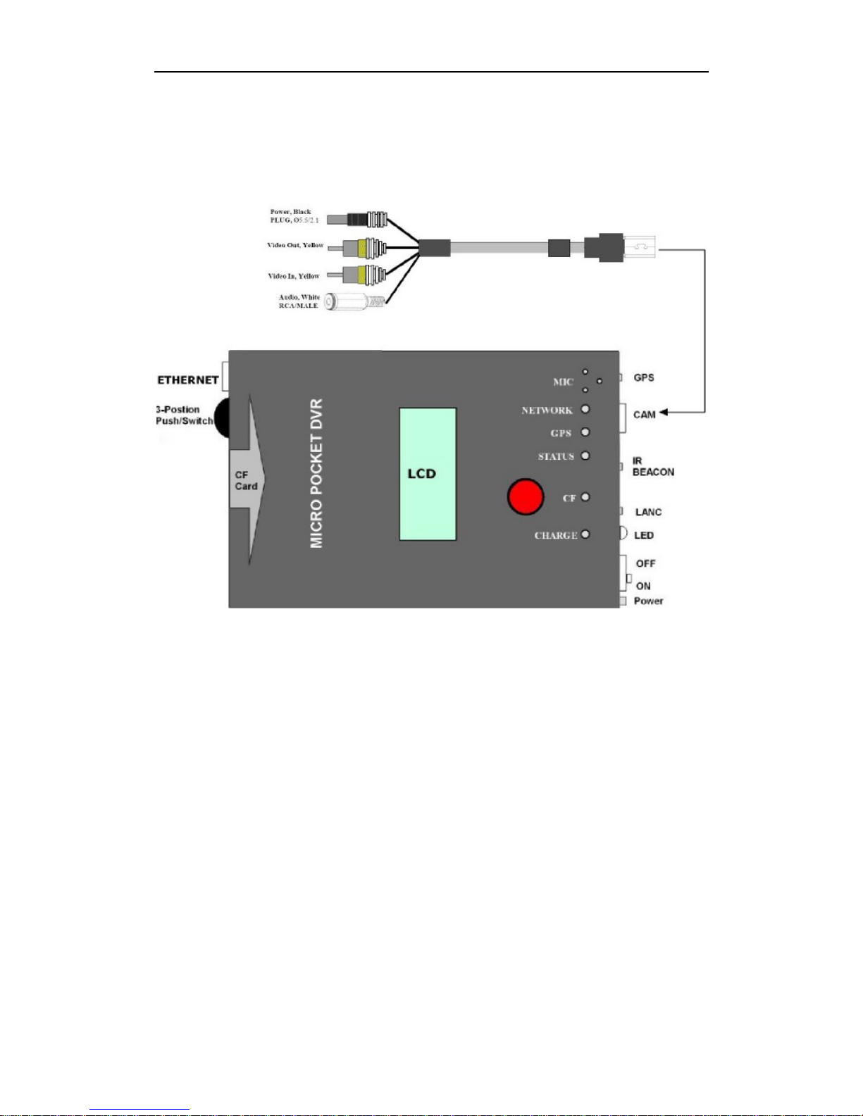
DR3 I support video output, you can connect external LCD or monitor to preview
real-time recording video & adjust angle of view of camera.
Page 12
Installation
- 6 -
2.3.2 DR3 II
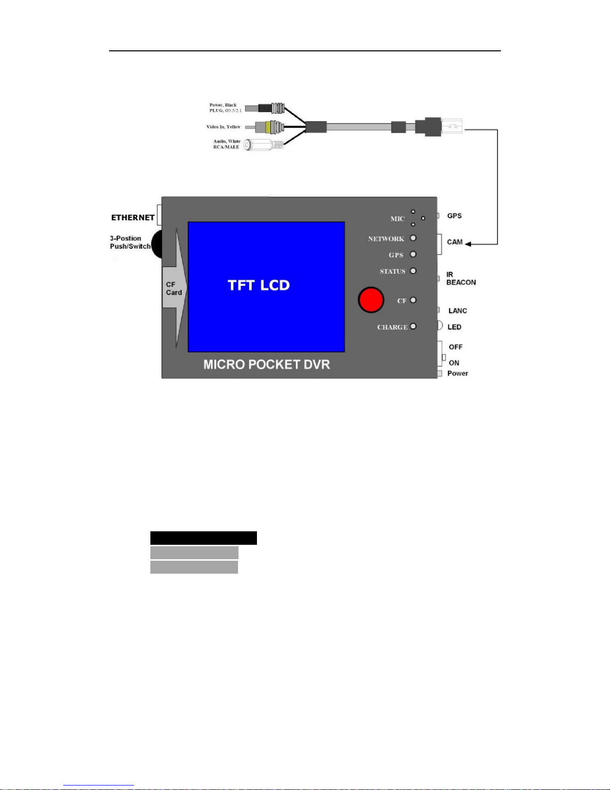
DR3 II has no enough power for external LCD or monitor because it has large TFT
LCD, you can preview real-time recording video & adjust angle of view via camera
on TFT LCD on DR3 II.
2.4 Video and Audio Interface
If the DR3 is configured RCA video interface & standard 3.5mm audio jack, the colors
correspond to:
Yellow RCA Interface
- Video Input/Output
Black 3.5mm Jack
- Audio/Microphone
Black 3.5mm Plug
- Power Output
2.5 Button/Bullet Camera Interface
Some button cameras can connect to DR3 directly without the jump cable if the
interface of button camera conforms to the Multi-Connect interface in Appendix.
2.6 Eject CF Card
1) Wait until the LED turns green
Page 13

DR3 DVR User Manual
- 7 -
2) Disconnect power adapter & Switch off power from the internal battery
3) Eject CF card
Page 14
Operation of DR3 DVR
- 8 -
3. Operation of DR3
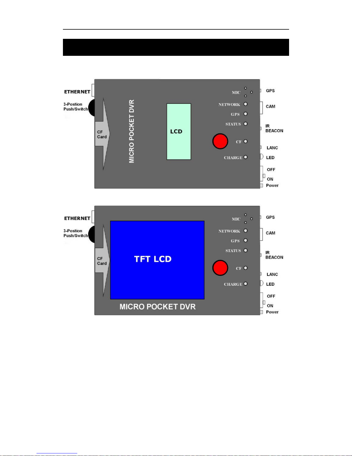
DR3 I
DR3 II
3.1 Quick Start
No configuration is required to start recording with the DR3.
The operation of the DR3 is quiet simple. There are two push buttons, REC button and
3-Position switch. An LED is used to indicate the status of operation.
Page 15
DR3 DVR User’s Manual
- 9 -
3.2 Push Button
3.2.1 RECORD
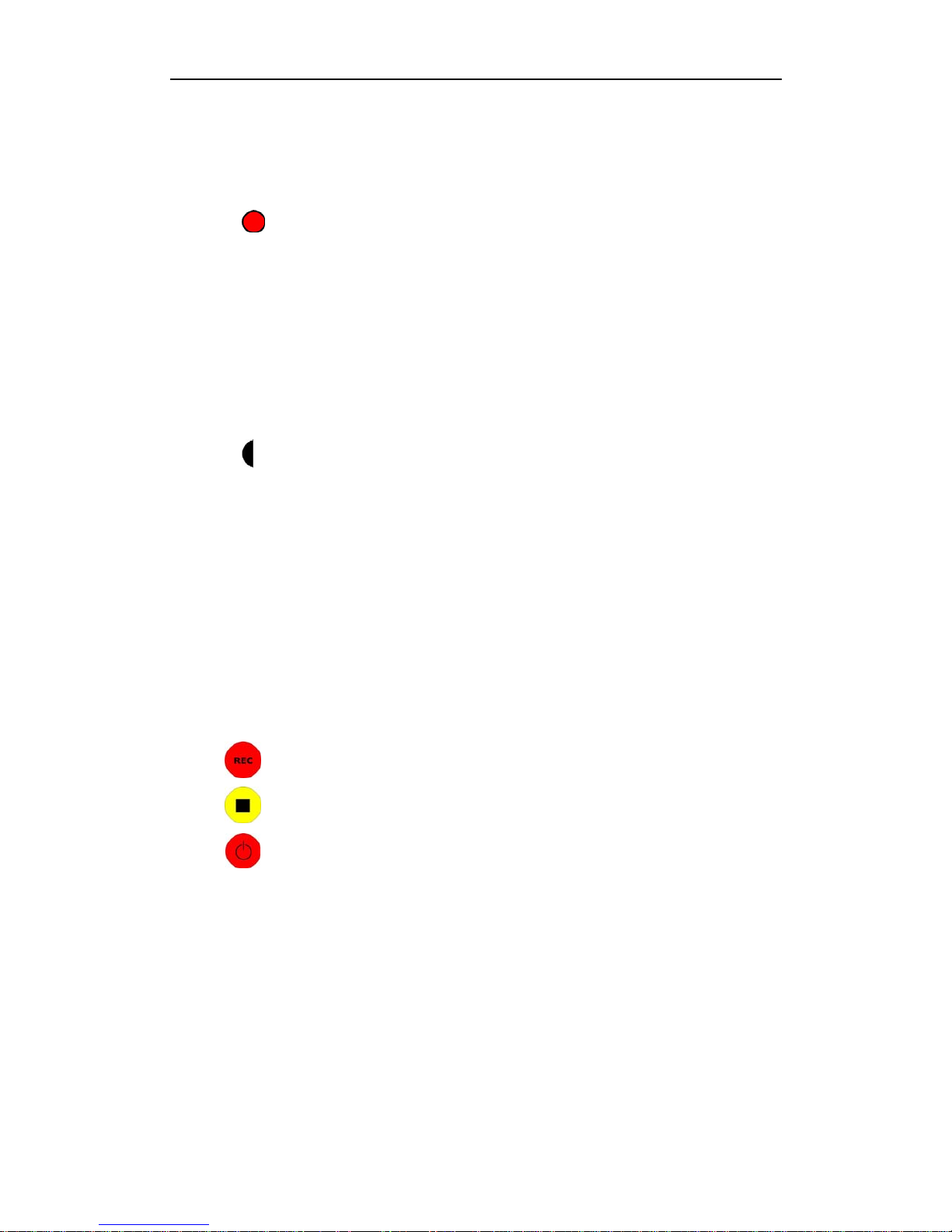
Press the (REC) button on top of DR3 for at least one second to start recording.
The LED will flash red and you will hear three beeps.
The flash frequency is about 3 times per second. Slower flash frequency means no
video signal is connected.
3.2.2 STOP
Press the (STOP) 3-Position button for at least three seconds to stop recording. The
LED turns to green & you will hear 2 beeps.
It will take a short while to save buffered data after stopped. The power can not be turn
off until the LED changes to green. Early eject the CF card will cause destroy of video
file integrity. Disconnect AC power adapter and switch off battery before eject CF card.
3.3 Infrared Remote Control
Infrared remote control is optional for DR3.
Three buttons are defined currently:
Start recording
Stop recording
Keep pressing to make DR3 in Standby/Wakeup mode
3.4 Infrared Remote Control for 4 Channel DR3
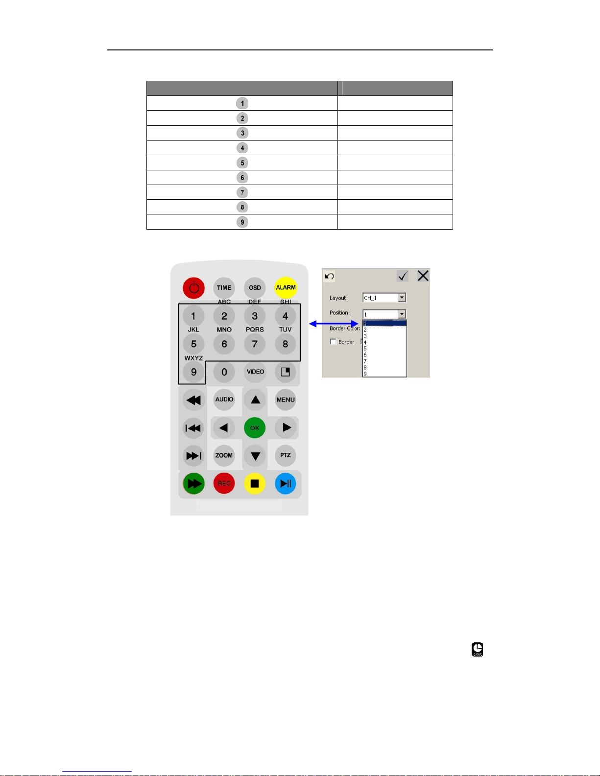
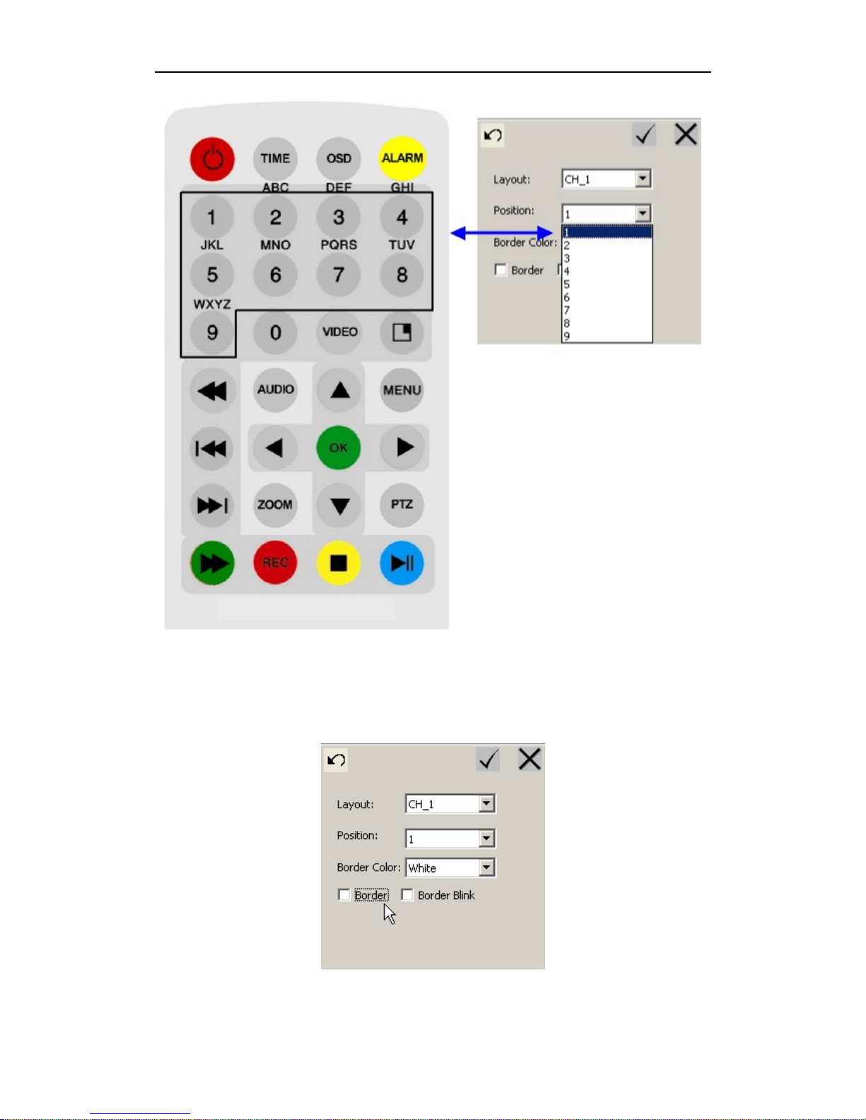
The numeric key on the IR remote controller controls 9 positions of Picture-In-Picture,
you can configure it & select any one array method as your default array using the DR3
Desktop.
You can switch the array method using numeric key on the IR remote controller directly
when you record the video using 4 Channel DR3. The numeric key 1~9 is opposite with
9 items in Position pull down menu.
Page 16
Operation of DR3 DVR
- 10 -
Numeric Key on IR remote Controller Item in Position Menu
1
2
3
4
5
6
7
8
9
Table showing numeric key on IR remote controller & Position menu
NOTE :
Numeric key on the IR remote controller are used for 4 channel DR3 only.
Numeric key on the IR remote controller are used only when you set
Layout to PIP on 4 Channel area.
3.5 LANC Remote Control
The DR3 support multi-version LANC Remote Control, please power off DR3 &
unplug AC Power adapter, then plug LANC remote control into LANC jack with
logo.
NOTE : Drivedata CES Remote Control is supported by the DR3.
Page 17

DR3 DVR User’s Manual
- 11 -
Power on the DR3, after booting is finished, you can control the DR3 start/stop
recording using LANC remote control. And you can power off DR3 & power on it
again.
After the DR3 starts successfully, the status LED on LANC remote control will display
green. Press the button on the center of LANC to start recording, and the status LED on
LANC will flash red & the unit beeps 3 times once started successfully.
Press button again, the DR3 will stop recording; the status LED on LANC turns to
green.
Holding the button on LANC for approx 3 seconds untill the status LED on LANC
flashes red. This will power down the DR3, when the DR3 powers down, the status
LED on LANC turns to yellow.
In power off status, press button on LANC to power up the DR3 again.
NOTE : DO NOT PLUG OR UNPLUG LANC REMOTE CONTROL WHEN
DR3 POWER ON & AC POWER ADAPTER IS CONNECTED !! YOU MUST
POWER DOWN THE DR3, UNPLUG AC POWER ADAPTER, THEN
PLUG/UNPLUG LANC REMOTE CONTROL.
3.6 Video Quality
LQ: Record video using 1Mbits/s & video based on CIF/SIF resolution.
EP: Record video using 2Mbits/s.
LP: Record video using 4Mbits/s.
SP: Record video using 6Mbits/s.
HQ: Record video using 8Mbits/s.
The recorded file size is dependent on the complexity of movement objects. The
following is the estimated recording time:
LQ : 100 min/GB
EP : 60 min/GB
LP : 40 min/GB
SP : 20 min/GB
HQ : 15 min/GB
Larger storage cards can yields longer recording time and better picture quality. For
example, current capacities of CF card on the market are from 512MB to 16GB. 4GB
CF cards can record 4 hours in EP mode.
Page 18
Operation of DR3 DVR
- 12 -
EP mode is recommended for slower moving or still background scene with some
moving objects in front. SP mode is recommended for fast moving background scenes.
3.7 Video File Name
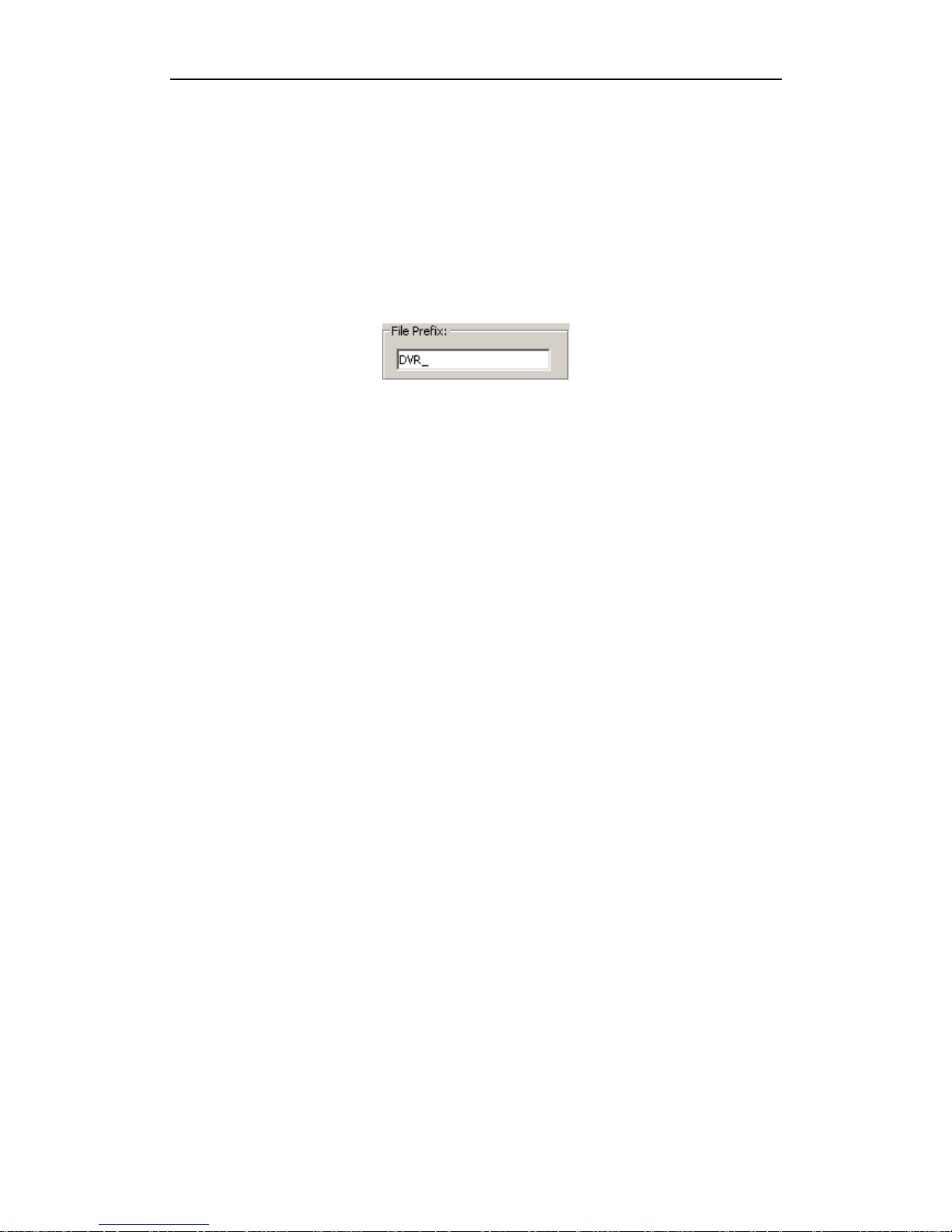
Recording video file name starts with DVR_ by default. The file name will be
DVR_xxx.avi. XXX is incremental from 000 to 999. The prefix DVR_ can be modified
in DR3 Desktop software.
Page 19
DR3 DVR User’s Manual
- 13 -
4. DR3 Status
4.1 Status of DR3
☯ Power up: LED is yellow for less then 1 second.
☯ Self diagnostics: LED is red for about 10 seconds.
☯ Normal: LED is green. Means it is ready to record.
☯ Recording: red LED will flash about 6 times/second.
☯ CF full: yellow LED will flash.
☯ Battery Low: Recording is stopped automatically. LED flash 4 times and enters
sleep mode
☯ Standby: LED is yellow. Only the (POWER) button or LANC can wake it up.
☯ No Video: LED will slowly flash red whilst trying to record.
4.2 Preview System Information via Shortcut Key
When DR3 starts successfully, you can turn 3-Position switch to LEFT/RIGHT or
UP/DOWN to preview system information of DR3.
4.2.1 DR3 I
Turn 3-Position switch to LEFT once to display current date & time on DR3.
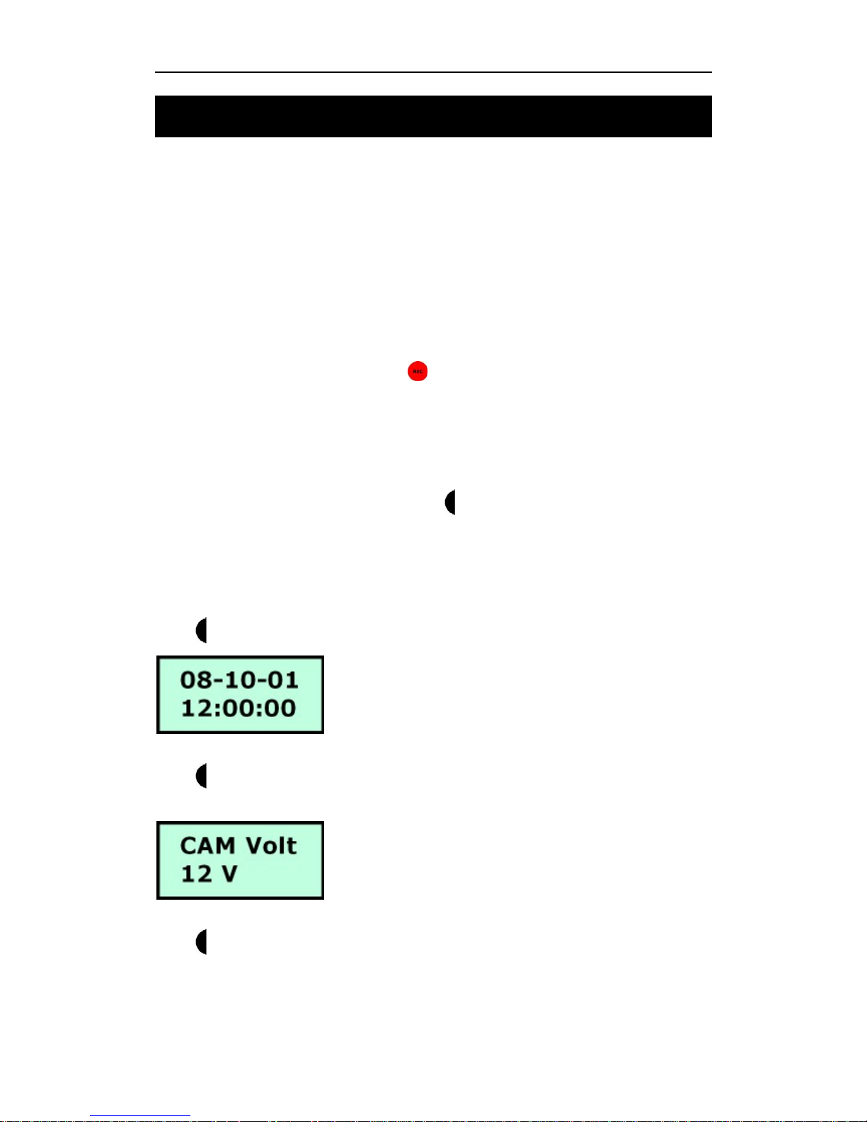
Turn 3-Position switch to LEFT twice to display current output power voltage for
external camera.
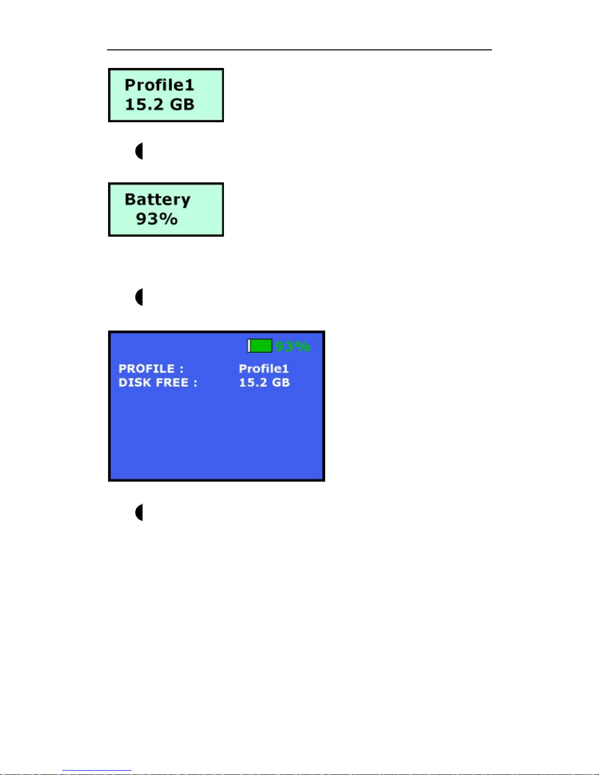
Turn 3-Position switch to RIGHT once to preview current profile item & available
storage space on CF card that insert into DR3.
Page 20
DR3 DVR Status
- 14 -
Turn 3-Position switch to RIGHT twice to display current energy of internal Li-Ion
Polymer battery.
4.2.1 DR3 II
Turn 3-Position switch to UP once to preview current profile item & available
storage space on CF card that insert into DR3.
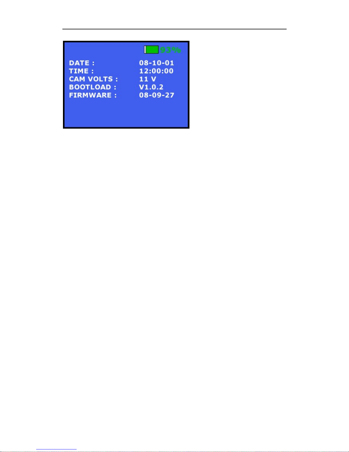
Turn
3-Position switch to DOWN once to display current date & time, output
power voltage for external camera, current boot loader & firmware information on
DR3.
Page 21
DR3 DVR User’s Manual
- 15 -
Page 22

Replay Video
- 16 -
5. Replay Video
5.1 Software
It is simple to replay video recorded on CF card. Media player can play the video files
directly within Windows.
DivX Codec or player has to be installed if no related components are installed on PC.
You can download DivX decoder from internet & install it. We recommend the use of
VLC media player which can be downloaded for free on the internet.
5.2 Card Reader
High speed card readers are recommended for read and replay of recorded video. If the
card reader is fast, your PC can replay video instantly from the CF card without coping
video file to PC hard disk first.
5.3 PCMCIA Interface
Most laptops have a PCMCIA interface. CF card with a PCMCIA adapter can be read
directly by Laptops with this interface. Please select feat PCMCIA-CF Adaptor to
copy the video files to PC and then replay the video files because PCMCIA is relatively
slower.
Page 23
DR3 DVR User’s Manual
- 17 -
6. Install DR3 Desktop
6.1 DR3 Desktop Installation
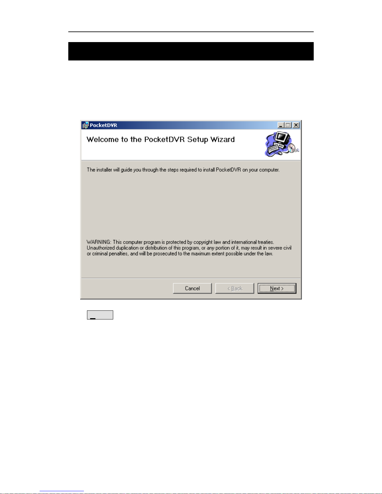
Install DR3 Desktop before you use the DR3 for the first time. Run setup.exe to install
DR3 Desktop.
Click Next > button to continue installation setup.
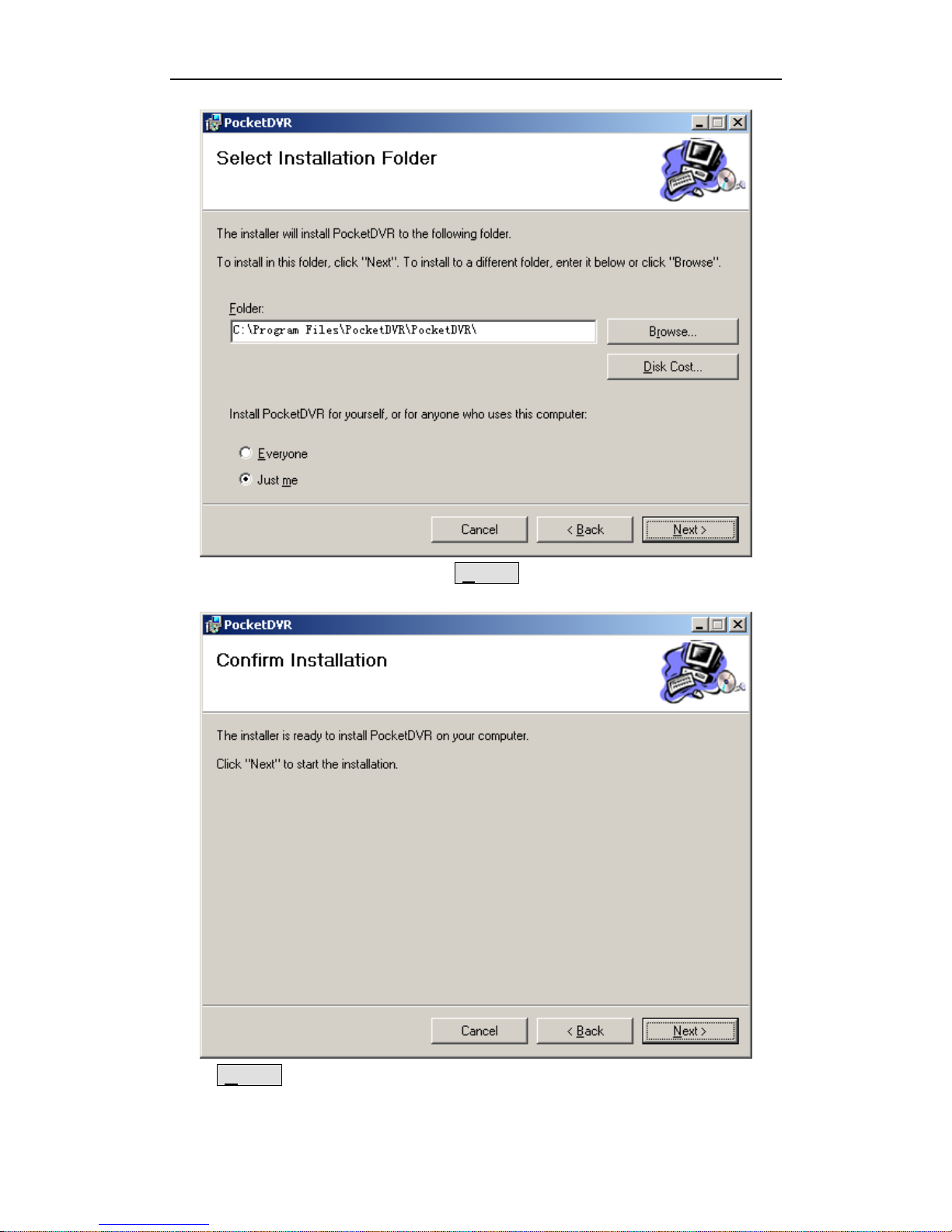
During the installation process, you can select the target folder or use the default folder
when software prompts you.
Page 24
Install DR3 DVR Desktop
- 18 -
After you select the target folder, Click Next > button to confirm it.
Click Next > button to start DR3 software install.
Page 25
DR3 DVR User’s Manual
- 19 -
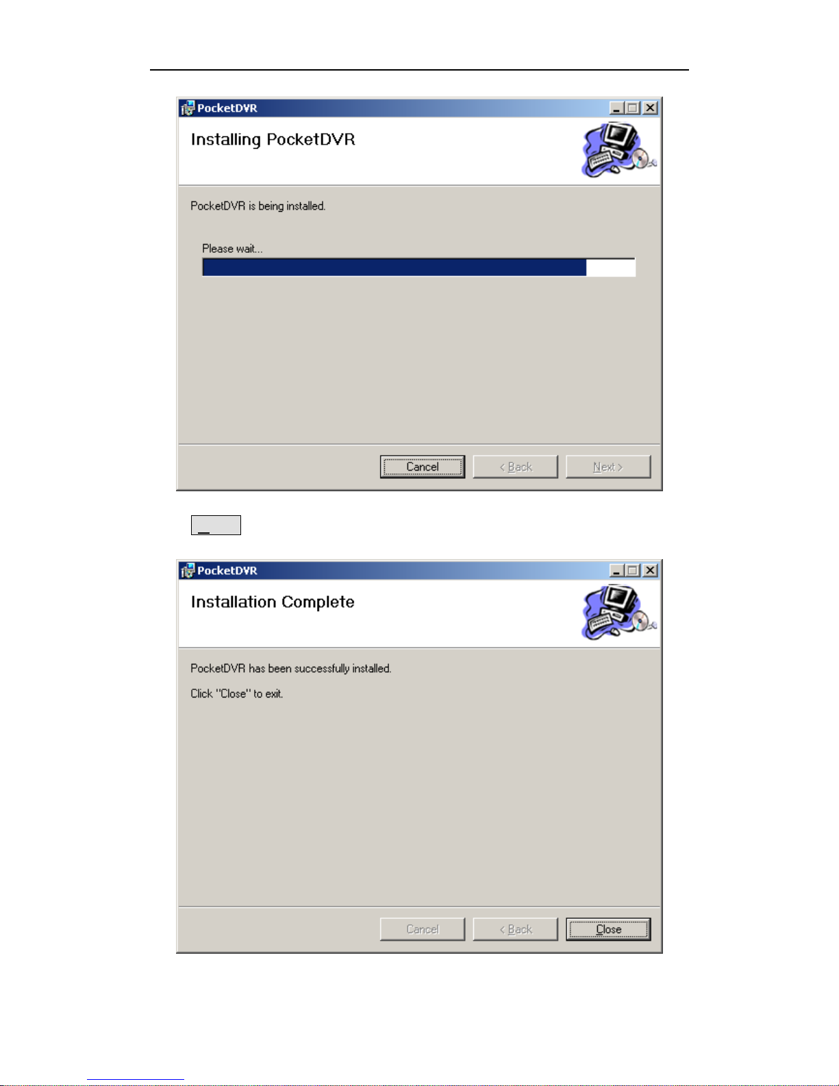
Click Close button to finish it when installer prompt you the installation is
successfully.
Page 26

Install DR3 DVR Desktop
- 20 -
After you install the DR3 Desktop, the software shortcut DR3 Desktop will be
generated on the desktop and DR3 program folder.
DirectX 9.0c is required to install and run DR3 Desktop.
Page 27
DR3 DVR User’s Manual
- 21 -
7. Configure DR3
The DR3 is initialized as DEVICE.INI under the root directory of the CF card. It must
be in the root directory of CF card. The DR3 will use the last time configuration if
DEVICE.INI not found during startup.
DR3 Desktop can configure the video format, average bit rate, audio in, TV system,
time stamp, Beacon, convert the recording video etc.
7.1 Start-Up DR3 Desktop
DR3 Desktop will detect Network connection between DR3 & PC in first, if Desktop
can’t detect valid network connection, then it will detect CF card that you want to used
in DR3, please connect CF card to PC via card reader before you start DR3 Desktop if
you don’t want to connect DR3 to PC via LAN.
The default sequence of DR3 Desktop is detecting valid network connection between
DR3 & PC in first, then detect CF card if it can’t find any valid net work connection.
Certainly, you can change the default detection method in DR3 Desktop software.
7.1.1 Startup Desktop software via Network Connection
Connect Network Sync cable that in package between DR3 & PC or switch/HUB in
first, then double click to start-up DR3 Desktop.
DR3 Desktop will search valid network connection.
After DR3 Desktop detects valid network connection, it wills start-up successfully.
Page 28
Configure DR3 DVR
- 22 -
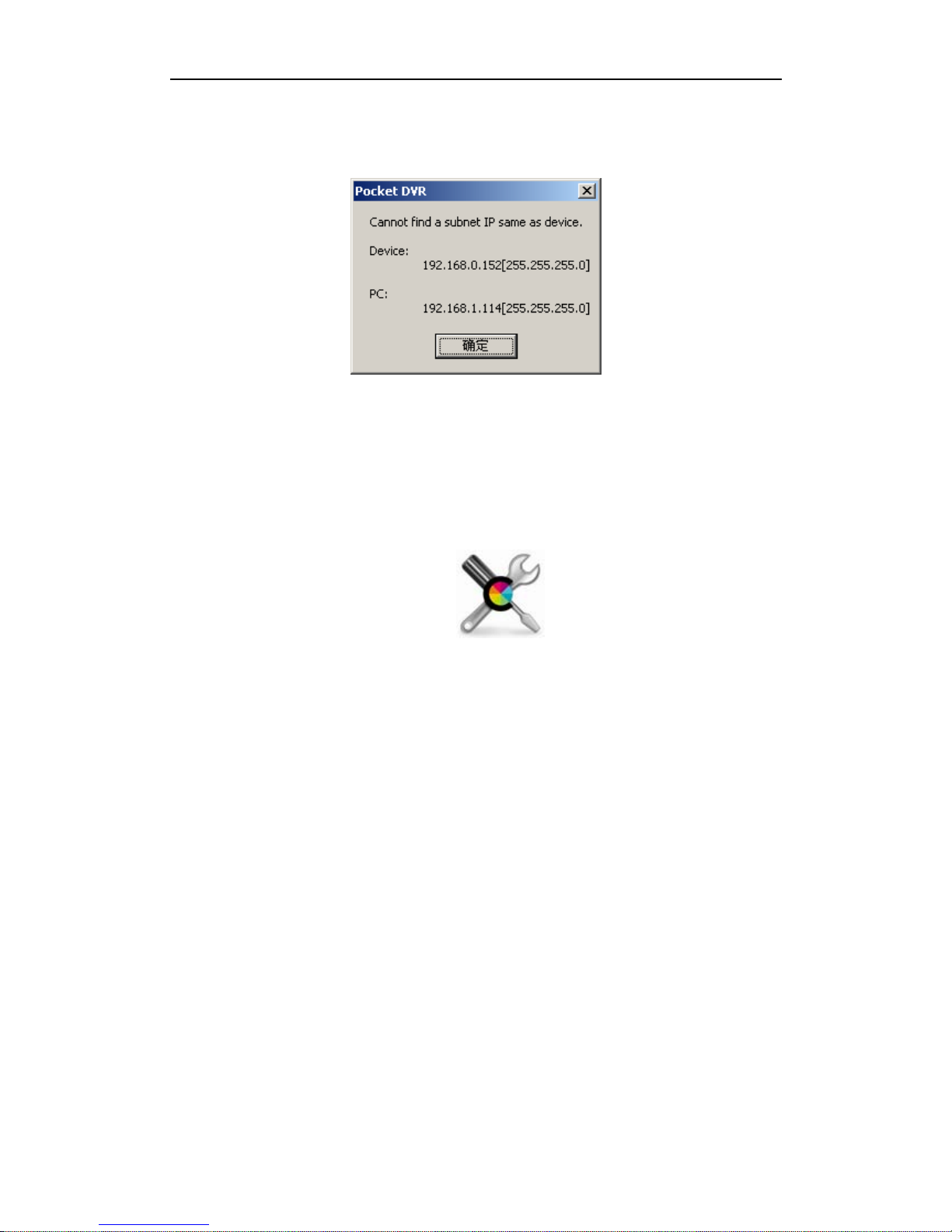
The default IP address of DR3 is 192.168.0.152, please ensure your PC on same IP
segment for first connection. If your PC & DR3 with different IP address segment,
Desktop software will prompt you.
You can change IP address of your PC to same IP segment with DR3, such as
192.168.0.100, and then restart Desktop software again.
After you startup Desktop software successfully, you can change IP address of DR3 to
same IP segment with your local LAN.
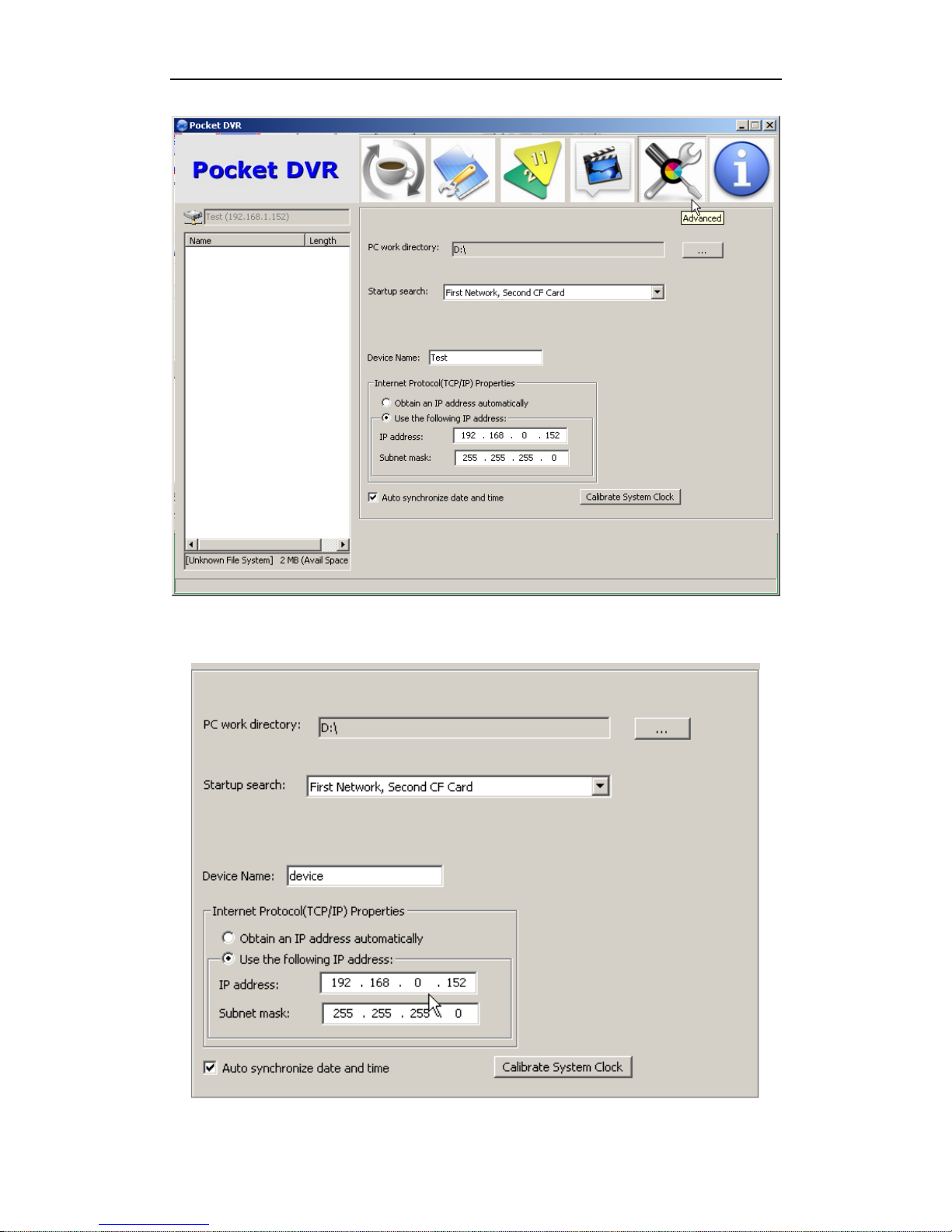
Click Advanced Configuration button to configure network
environment of DR3 connection.
Page 29
DR3 DVR User’s Manual
- 23 -
You can change IP address of DR3 manually.
Page 30
Configure DR3 DVR
- 24 -
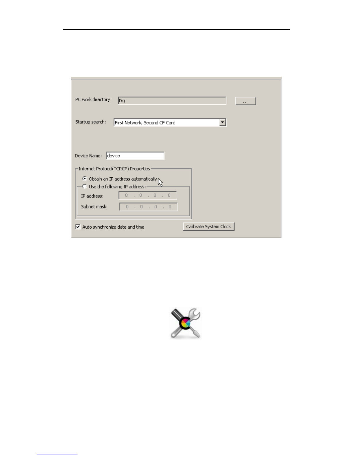
Or you can let DR3 obtain IP address from DHCP server on your local LAN if you
connect DR3 to router or switch. But please notice, the router or switch that be
connected DR3 must support MDI/MDI-X connection.
7.1.2 Startup Desktop software via CF card Connection
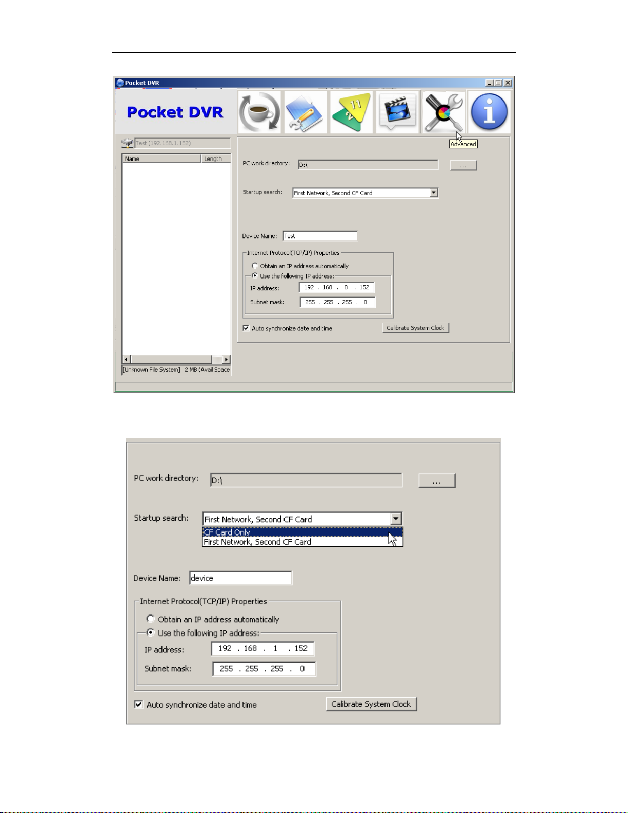
Change Startup Search option from default configuration to CF Card only, then you
can startup DR3 Desktop via CF card that connect to PC without network connection.
Click Advanced Configuration button to configure connection
configuration.
Page 31
DR3 DVR User’s Manual
- 25 -
Then set Startup Search option to CF Card Only item.
Page 32
Configure DR3 DVR
- 26 -
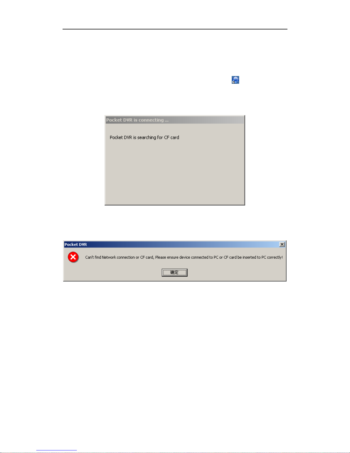
After you configure it, you can startup Desktop software only via CF card without
network connection for the future.
Connect CF card to PC via card reader in first, then double click to start-up DR3
Desktop.
DR3 Desktop will search CF card on PC.
If CF card can’t be connected to PC correctly or no CF card be connected to PC, DR3
Desktop will display error message to prompt you connect CF card to PC correctly.
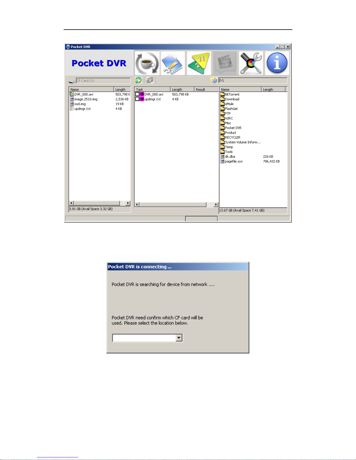
If CF card that you connect to PC had been used in DR3 or be initialized by DR3
Desktop, DR3 Desktop will detect the DEVICE.INI file on the root directly of CF card,
and DR3 Desktop will start-up automatically.
Page 33
DR3 DVR User’s Manual
- 27 -
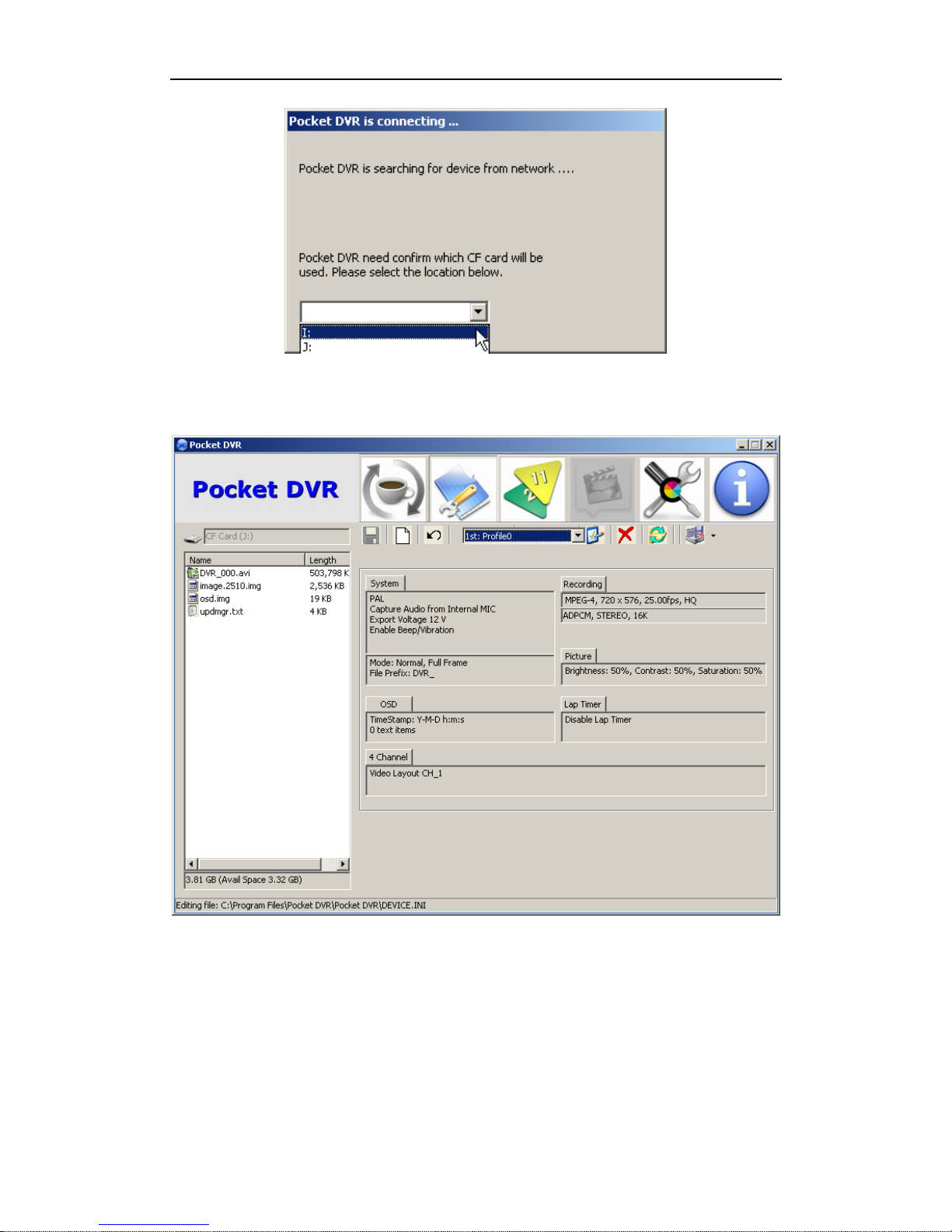
If DR3 Desktop detect a new CF card, system will prompt you select a correctly disk
that point to CF card.
After you select correctly disk, DR3 Desktop will initialize CF card and create
DEVICE.INI configuration file on root of CF card automatically.
Page 34
Configure DR3 DVR
- 28 -
Once DR3 Desktop finished initialization, it wills start-up automatically.
7.2 DR3 Desktop Description
7.2.1 DR3 Desktop Title Bar
Page 35
DR3 DVR User’s Manual
- 29 -
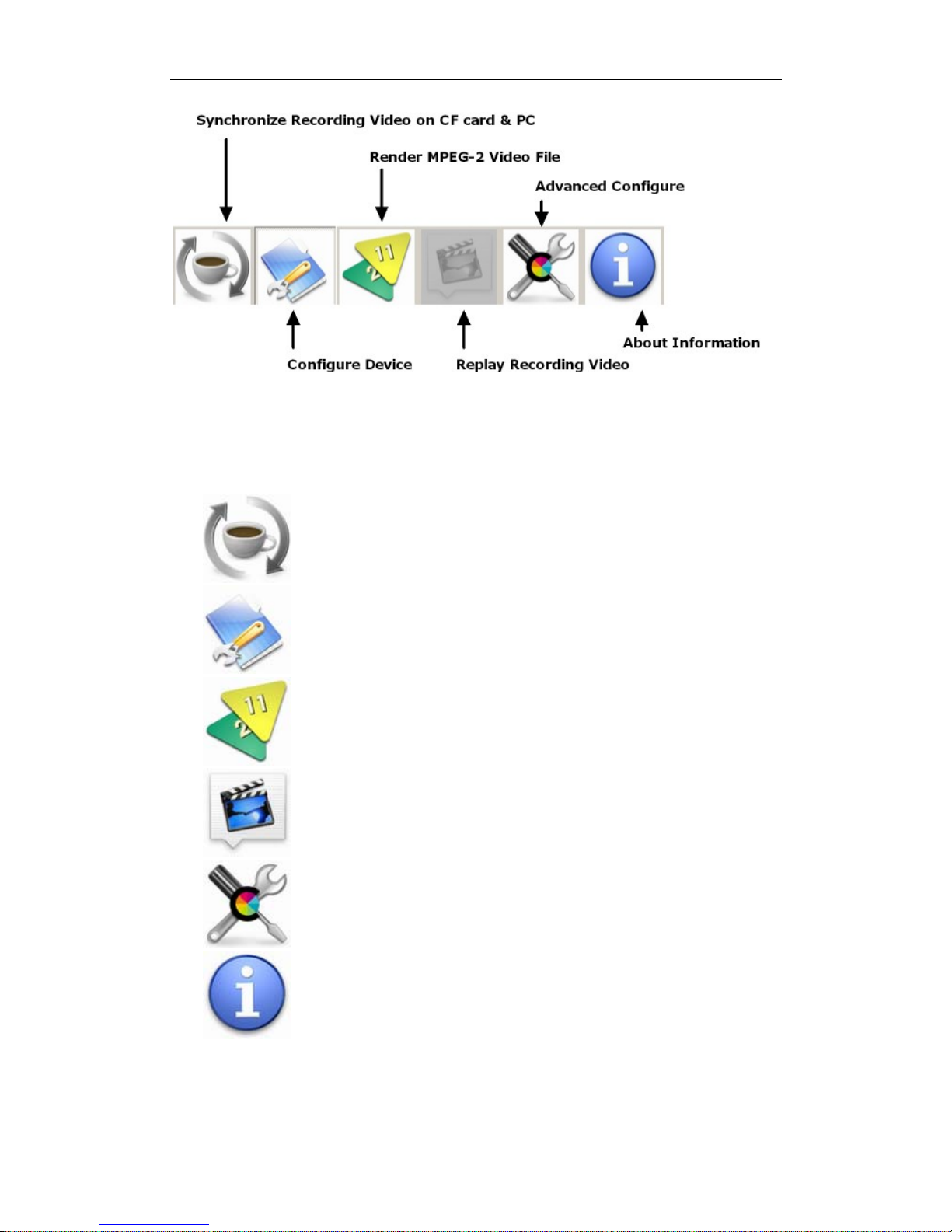
DR3 Desktop include six part, you can using DR3 Desktop to configure the video
format, average bit rate, audio in, TV system, time stamp, Beacon, convert the
recording video etc.
Sync :
Synchronize recording video file on CF card & PC.
Device Configuration :
Configure DR3 device.
Conversion :
Render MPEG-2 data to standard MPEG-2 video.
Play :
Replay recording video on CF card or PC.
Advanced :
Advanced system configuration.
About :
Details information of DR3 Desktop.
Page 36
Configure DR3 DVR
- 30 -
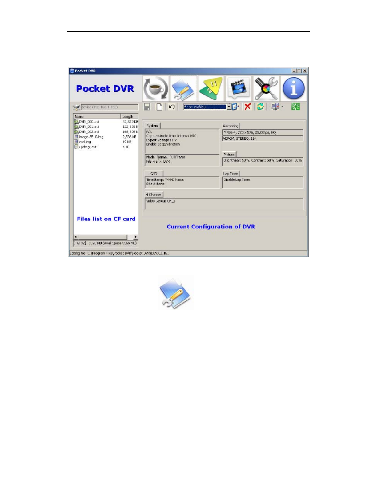
7.2.2 DR3 Desktop Interface
Click Device Configure button on the title bar to configure the DR3.
Page 37
DR3 DVR User’s Manual
- 31 -
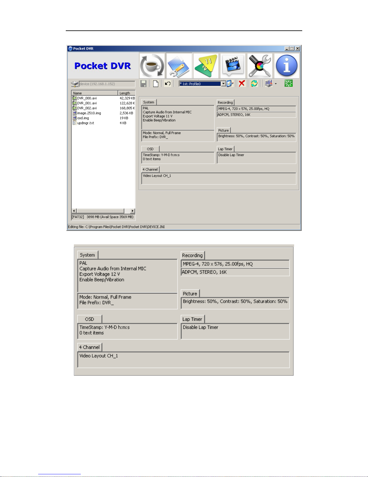
7.2.3 Save, Cancel & Reset Setting
In all pop configuration menus, you can save, cancel or reset setting to default.
Page 38
Configure DR3 DVR
- 32 -
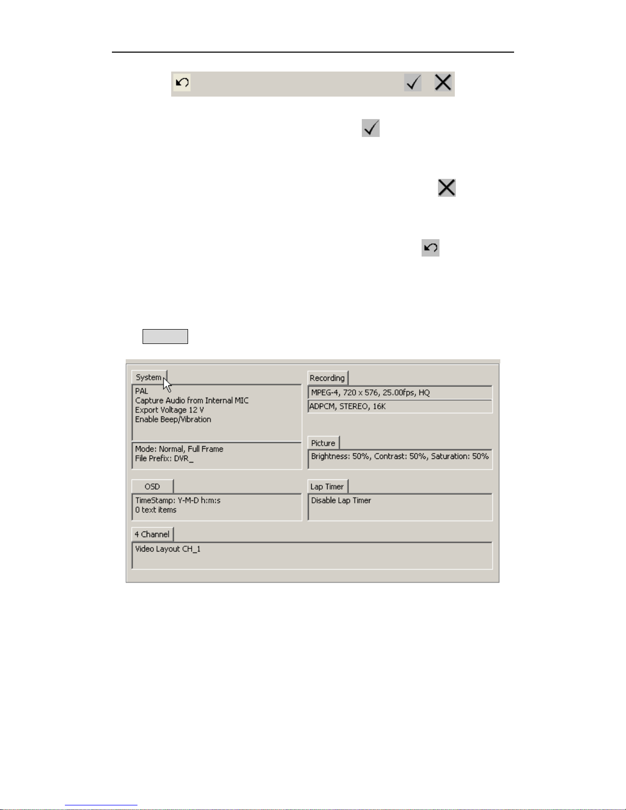
When you finish all setting, you can click OK button to save configuration & exit
current configuration menu.
If you want to cancel current modification, please click Cancel button to cancel &
exit current configuration menu.
If the configuration had been jumbled, you can click Reset button to restore
configuration to default setting.
7.3 Device Configuration
Click System tab to configure DR3.
Page 39
DR3 DVR User’s Manual
- 33 -
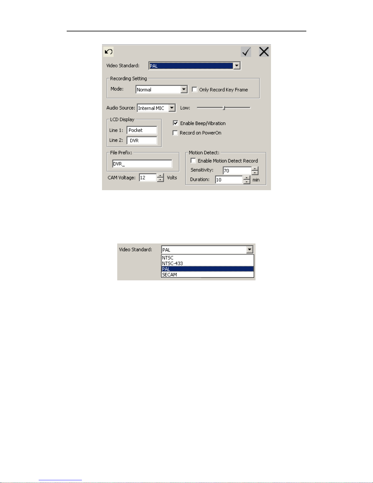
7.3.1 Video System
Please select correct video standard which corresponding to the video source of camera.
Default video standard is now PAL. It has to be changed for other video standard.
7.3.2 Beep/Vibration
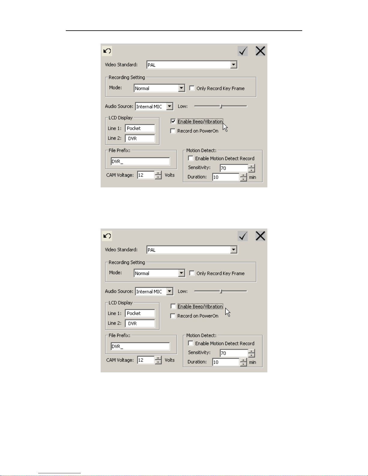
DR3 will beep or vibrate to warn you when it starts or stops recording, in some special
applications or occasion/environment, you may want to turn this function off, and you
can disable beep/vibration function.
Page 40
Configure DR3 DVR
- 34 -
The default configuration is Enable Beep/Vibration function; you can disable it in
DR3 Desktop.
Switch off Enable Beep/Vibration options in DR3 Desktop to disable it, now you can
operate DR3 in silent mode.
Page 41
DR3 DVR User’s Manual
- 35 -
7.3.3 Record on Power On
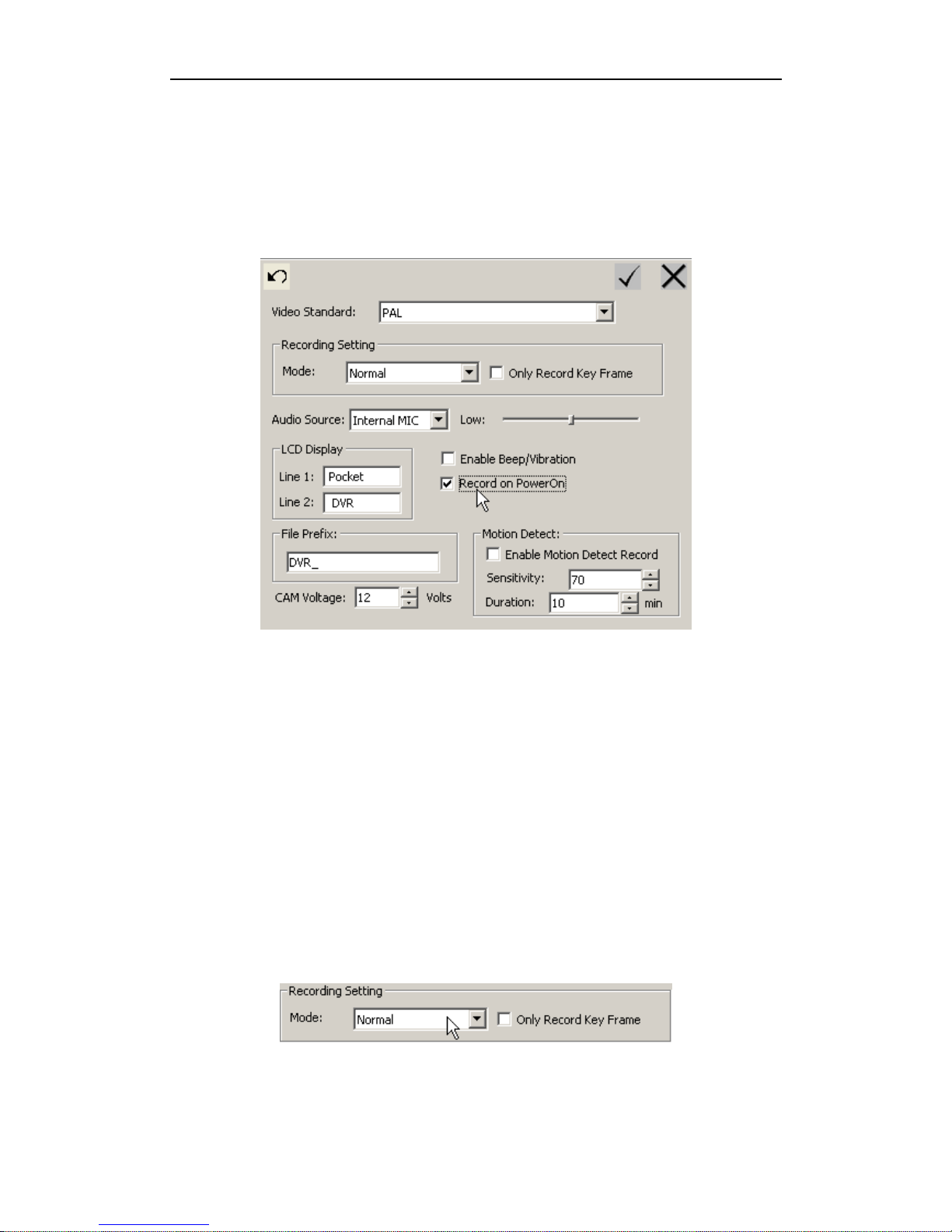
In some applications, you may need the DR3 to record automatically once the DR3 is
powered on.
You can switch on the Record on PowerOn option in the DR3 Desktop.
The default status of record is manual record via IR remote control, LANC remote
control or push button.
7.3.4 Recording Setting: Normal/Cycle Record, Key Frame & Motion Detection
You can configure the DR3 in normal record or cycle record mode.
7.3.4.1. Normal Record Mode
In normal record mode, DR3 will record video & save recording video in multi-single
video file, the maximum size of single recording video file is 2GB depend on limit of
system.
The default of record mode is Normal Mode.
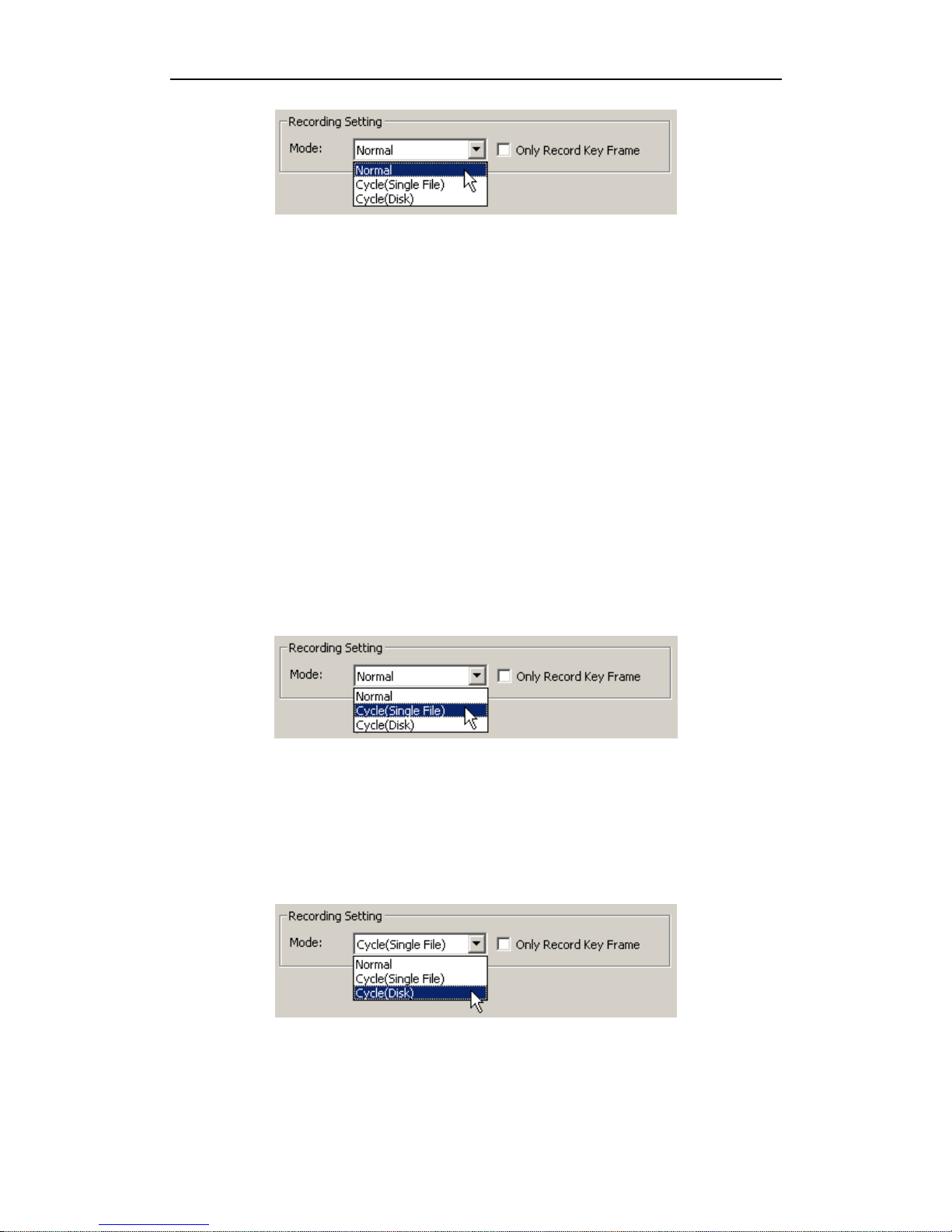
You can select Normal Record Mode option to enable normal record mode if current
configuration is cycle item.
Page 42
Configure DR3 DVR
- 36 -
If you want to use DR3 in a surveillance application, you can set the Record Mode to
Cycle Record mode.
7.3.4.2. Single File Cycle Record Mode
The DR3 has two cycle record modes, Single File Cycle Record & Full Disk Cycle
Record mode.
In Single File Cycle Record mode, the DR3 will save recordings in single file only, the
maximum size of single recording video file is 2GB, when video reaches the 2GB limit,
the system will save the new recordings from the begin of recording video file.
If your CF card is smaller than 2GB, the DR3 will save recording video in single file
only, when CF card is full, system will save the new recorded video from the beginning
of the recorded video file.
You can select Cycle (Single File) item in Record Mode option to enable Single File
Cycle Record mode.
7.3.4.3. Full Disk Cycle Record Mode
In Full Disk Cycle Record mode, the DR3 will record continually, when the CF card is
full, the DR3 will record the video overwriting the oldest recorded file.
You can select Cycle (Disk) item in Record Mode option to enable Full Disk Cycle
Record mode.
If you set the DR3 in cycle record mode, all old recorded video file on the CF card will
be deleted on system startup.
Page 43
DR3 DVR User’s Manual
- 37 -
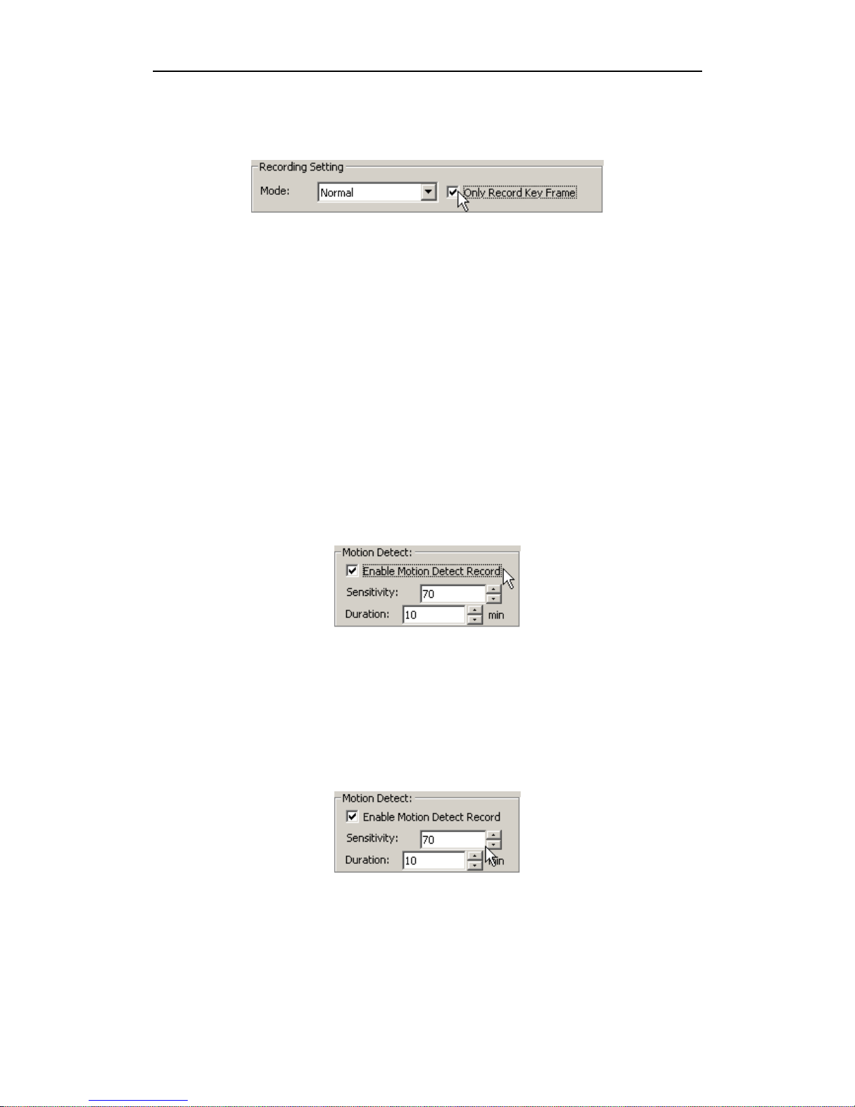
7.3.4.4. Only Record Key Frame
If you want to record video in surveillance application, you can record key frame only
to decrease the size of recording video & increase recording time for a same CF card.
In this option, DR3 will record one frame per 15fps. In PAL video standard, approx 3
frame per 2 second be saved; in NTSC video standard, approx 2 frame per second be
saved.
If you select this option, system will save video only and that the sound will be
forsaken.
NOTE: The option is only for MPEG-4.
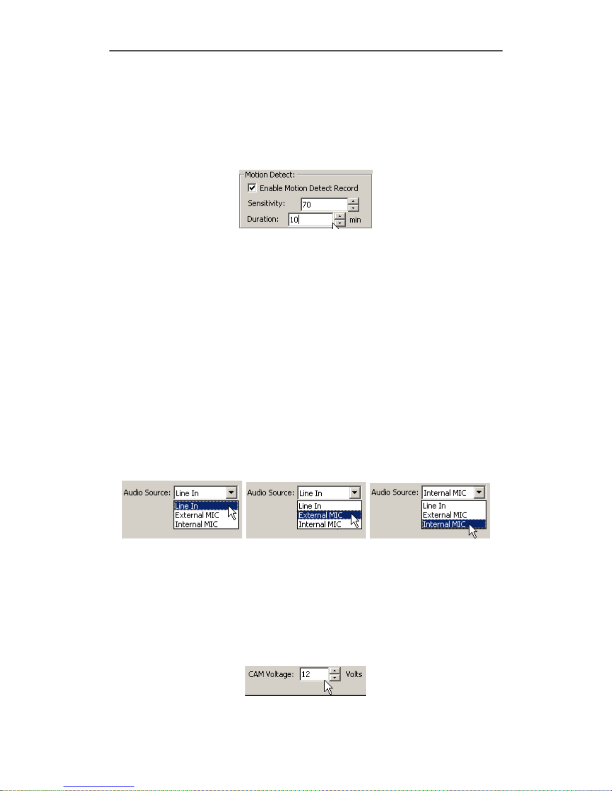
7.3.4.5. Motion Detection
When you use DR3 on surveillance application, such as security surveillance, scout,
wildlife protect & observe etc, you need record all useful video over a long time range
on a CF card, you must forsake useless resting video to save storage space on CF
card. You can enable Motion Detection function to get it.
The default configuration of Motion detection is disabling, you need enable it if you
want to use this function.
To avoid unconcerned locomotors object to active Motion Detection, you can set
Sensitivity of Motion Detection, the value means the size proportion of locomotors
object than fully screen area.
You can estimate the size proportion of object that you want to catch, at once DR3
detect a locomotors object that match sensitivity value that you setting, it will begin to
record video automatically until duration time that you setting is finished.
The default value of Sensitivity is 70% of full recording video screen area.
Page 44
Configure DR3 DVR
- 38 -
DR3 will recording continuously until duration time is finished when Motion
Detection recording be actives. You can change Duration time depend on your
requirement to record all useful video or save more storage space on CF card.
The default value of duration time is 10 minutes.
DR3 will start recording at once Motion Detection be actives, it will stop recording
when duration time is finished, if DR3 detect other suited locomotors object in
duration time, the duration time will be postponed based on the last suited object.
Actual duration time is always timed based on the last suited locomotors object that
be detected by DR3.
Motion Detection function is only for MPEG-4 format.
7.3.5 Audio Source
Please select the correct audio in setting which is based on your actual audio input.
Default audio source is Line In, you need to select External MIC if you use an
external microphone, or you can select Internal MIC item if you use the internal
microphone in DR3.
The External MIC & Internal MIC option will increase gain of volume.
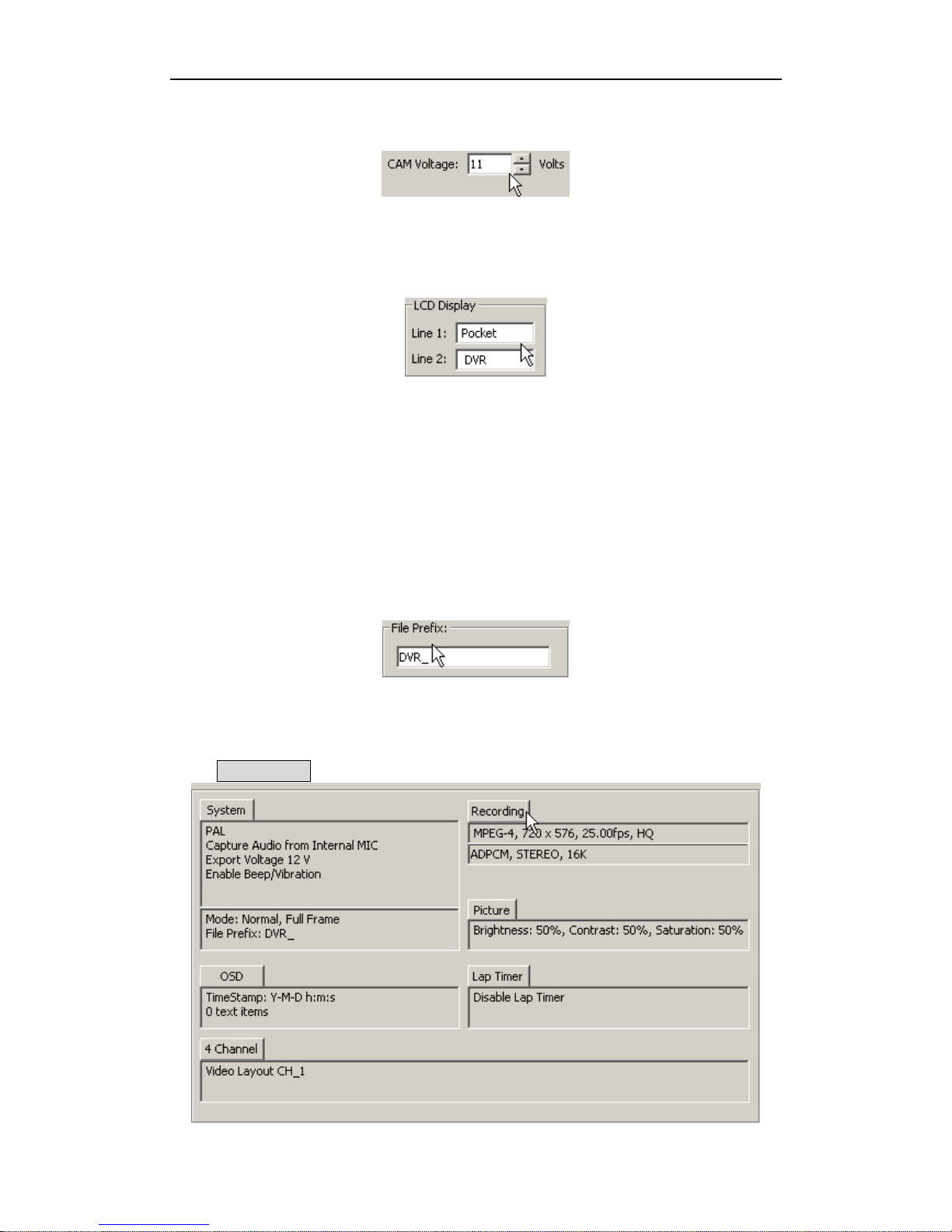
7.3.6 Output Voltage
DR3 can power external device via power output adapter on IRIS-RCA jump cable, you
can power external bullet camera or external LCD monitor, you can adjust output
voltage from 6V to 12V.
Page 45
DR3 DVR User’s Manual
- 39 -
If you want to power external bullet cameras more than one, please set the output
voltage lower than 11V, and you need connect AC power adapter for DR3.
7.3.7 LCD Display
You can customize the LCD message.
The maximum character of characters of every line is 8; you can use printable
characters only & exclude the character “~”.
7.3.8 Video File Name
Record file name starts with DVR_ by default. The file name will be DVR_xxx.avi.
XXX is incremental from 000 to 999. The prefix DVR_ can be modified in DR3
Desktop.
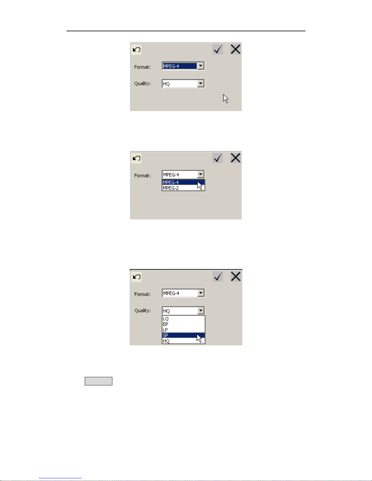
7.4 Recording Format & Quality
Click Recording tab to configure recording format & quality.
Page 46
Configure DR3 DVR
- 40 -
7.4.1 Video Format
Select MPEG-2 or MPEG-4 format for your recording video.
7.4.2 Video Quality
Select proper video quality based on the scene and required. Please refer to Video
Quality section.
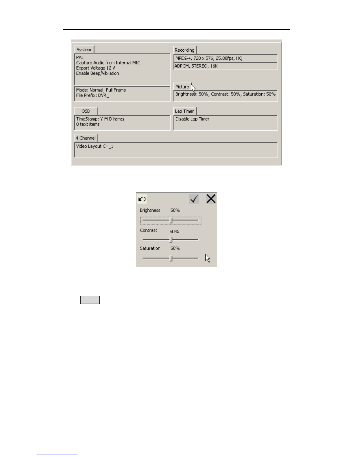
7.5 Picture Adjust
Click Picture tab to adjust picture of recording quality.
Page 47
DR3 DVR User’s Manual
- 41 -
You can adjust the brightness, contrast & saturation of the picture to get the best
quality. The default value is 50%.
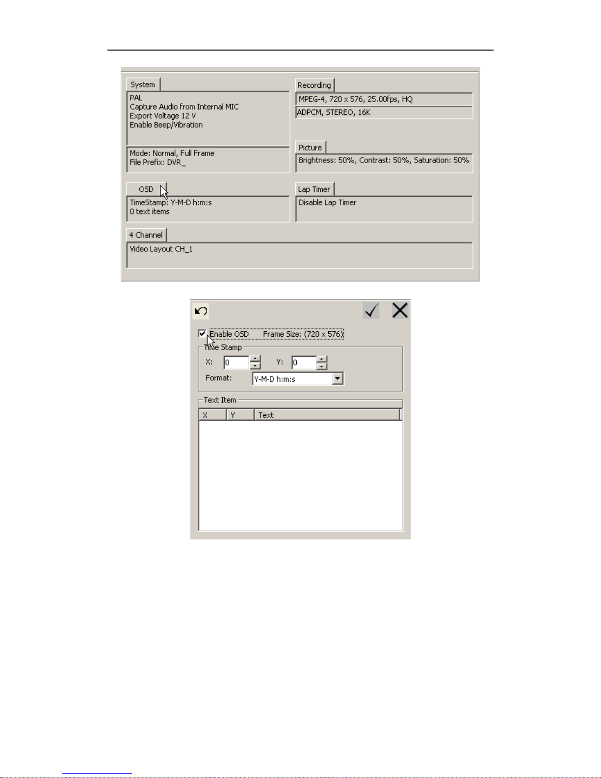
7.6 OSD Configuration
Click OSD tab to configure Time Stamp & OSD information.
Page 48
Configure DR3 DVR
- 42 -
You can display Time Stamp & customized OSD information on recording video
screen.
At once we enable OSD, the Time Stamp & special OSD information that you input
will display on screen & recording video.
7.6.1 Time Stamp
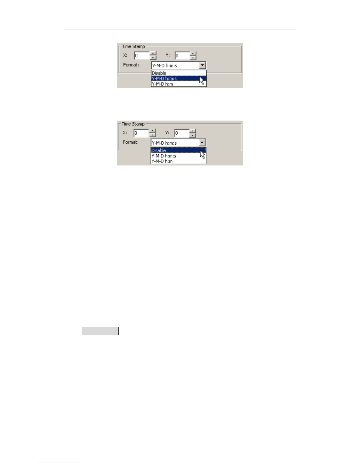
You can enable time stamp in two formats to stamp your recorded video with real date
& time.
Page 49
DR3 DVR User’s Manual
- 43 -
Certainly, you can disable Time Stamp features if you want to display customized text
OSD information in your recordings only & without date & time stamp.
You can display date & time stamp on anywhere of screen, set coordinates X & Y that
you want to posit data & time stamp.
The unit of X & Y coordinate is pixel; the value bound is 720x576 of PAL & 720x480
of NTSC video standard. The value of X coordinates is from 0 to 720, Y coordinates is
from 0 to 576 (PAL) or 480 (NTSC).
At once you don’t active Enable OSD option, Time Stamp & all customized text
OSD information will disappear on screen & recording video.
The default, OSD is disabling.
In DR3, priority of Beacon is higher than Time Stamp; the Time Stamp will be
disabling at once when the Beacon is enabling.
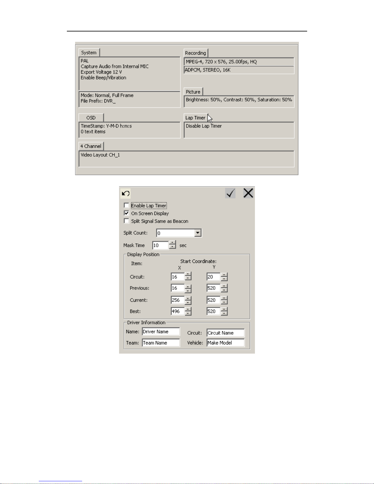
7.7 Configuration of Lap Timer
Click Lap Timer tab to configure Lap Timer.
Page 50
Configure DR3 DVR
- 44 -
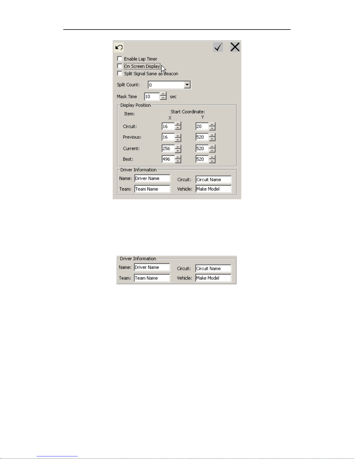
At once you enable Lap Timer function on DR3 /w Lap Timer edition, the Lap Timer
data will be recorded on recording video & separate text data file, always, but you can
select display it on screen of recording video, please disable On Screen Display
option.
Page 51
DR3 DVR User’s Manual
- 45 -
7.7.1 Set Driver Information
After enable Lap Timer function, you can record driver name, team, and circuit for
racing, make & model of vehicle in racing on screen of recording video.
You can modify these informations based on actual details information.
7.7.2 Beacon & Split Beacon
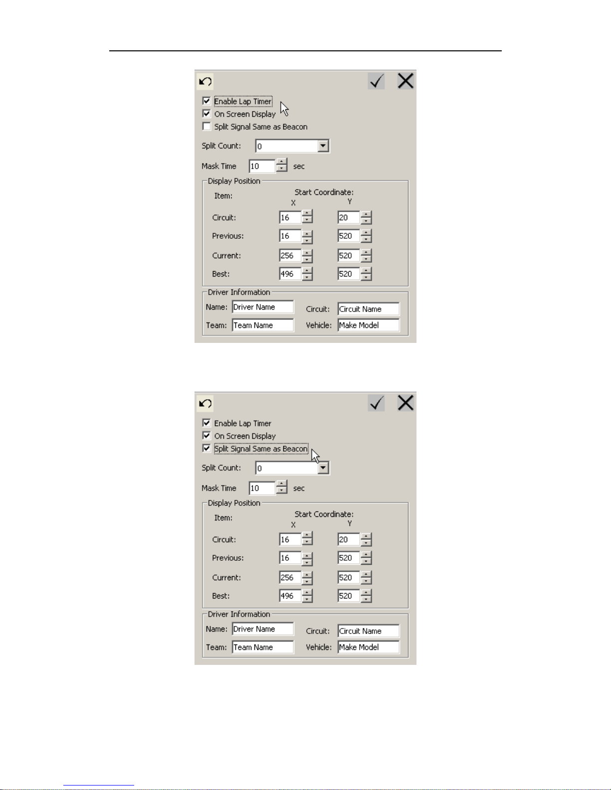
Set Beacon Enable to receive Beacon signal. The default is disabling.
Page 52
Configure DR3 DVR
- 46 -
If you use Split Beacon on racing, you must switch Split Signal Same as Beacon
option to enable it.
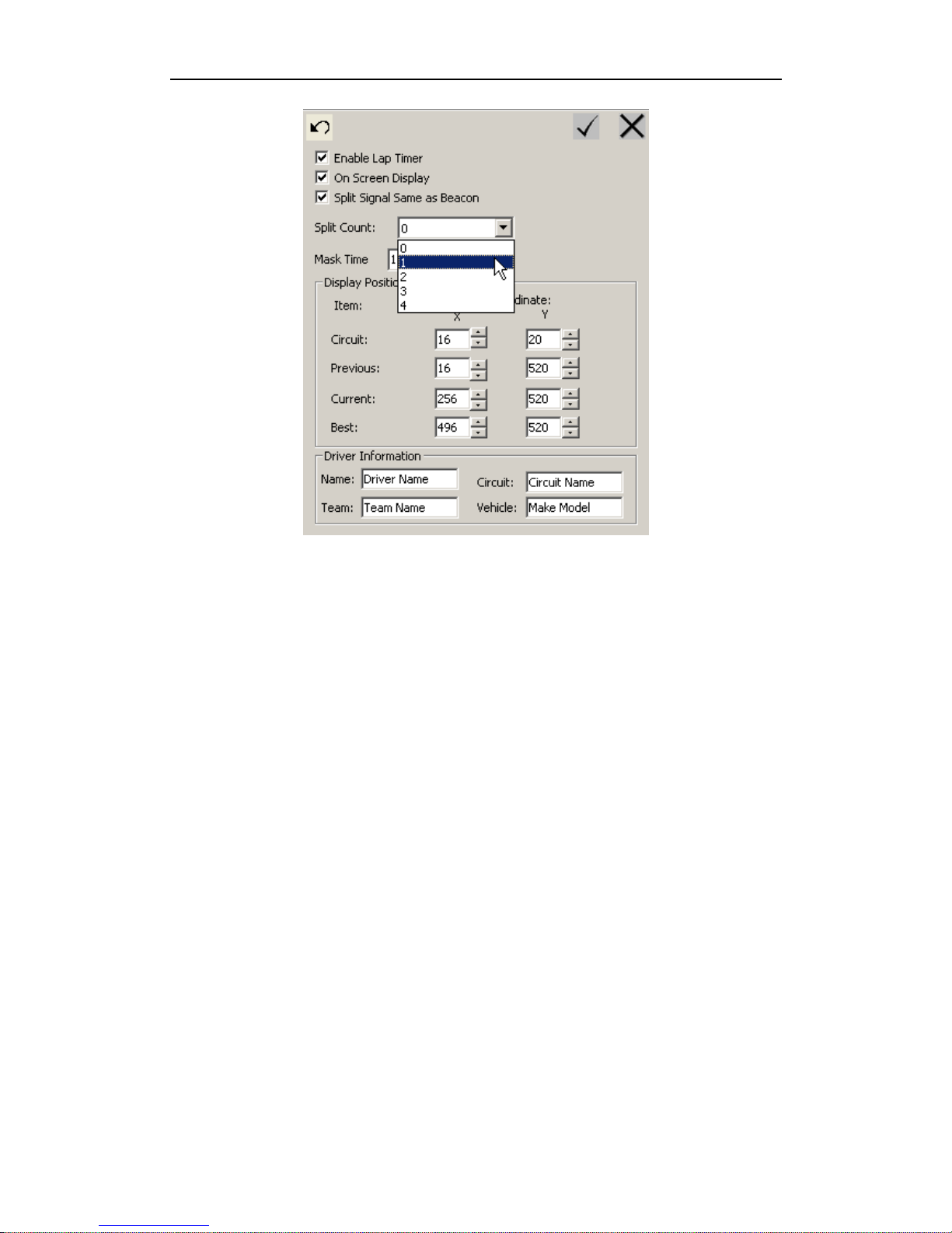
You can select the amount of Split Beacon for every loop; the maximum amount of
Split Beacon is four on every loop.
Page 53
DR3 DVR User’s Manual
- 47 -
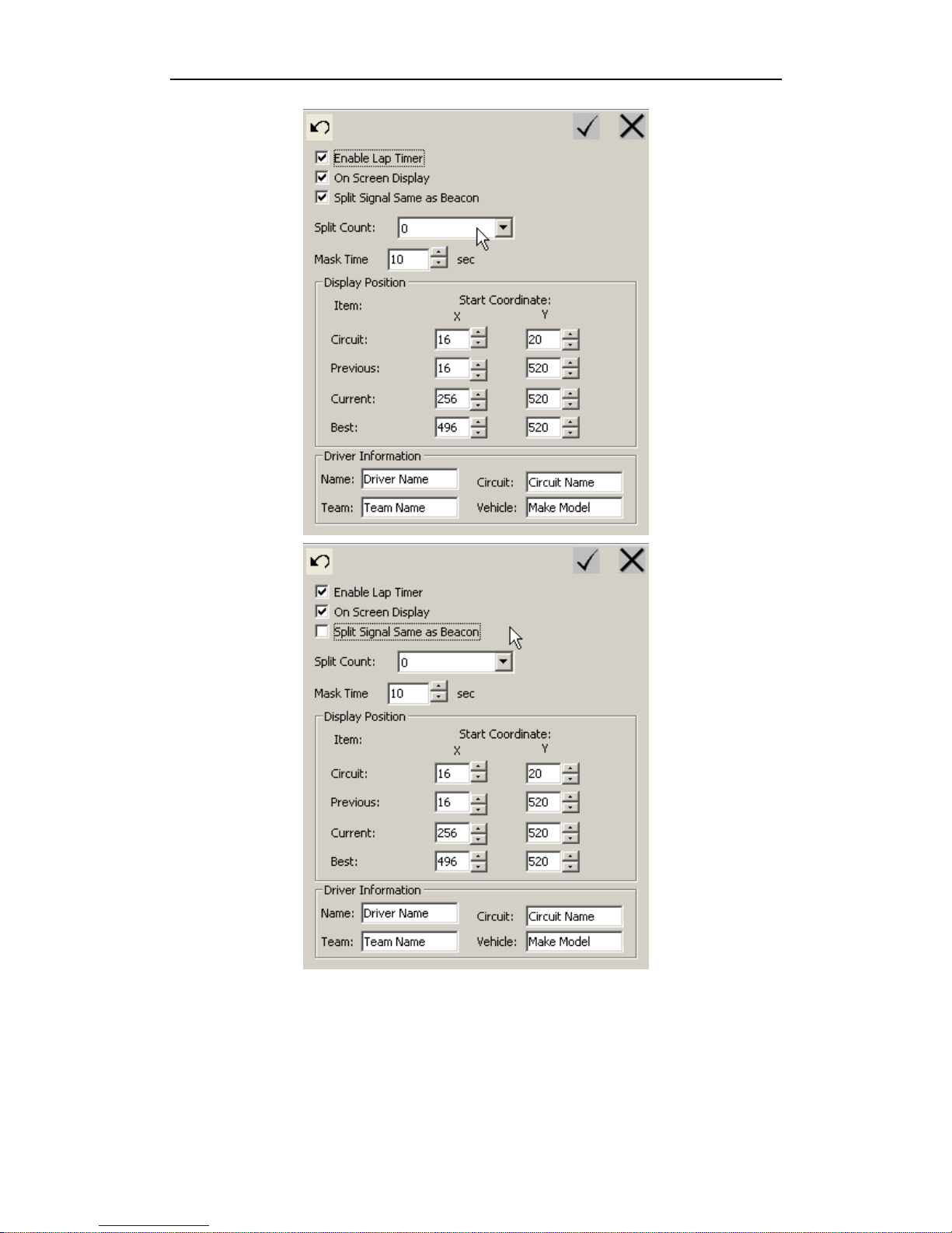
If you don’t use Split Beacon emitter on racing, please set the amount of Split Beacon
emitter to zero or disable Split Beacon option directly.
The default configuration of the amount of Split Beacon is zero.
Page 54
Configure DR3 DVR
- 48 -
DR3 can record most 129 loops Lap Timer data on single recording video.
The Time Stamp will be disabled when you enable the beacon function.
Page 55
DR3 DVR User’s Manual
- 49 -
The Beacon Configuration option is only for the special edition of DR3 with Lap Timer
function.
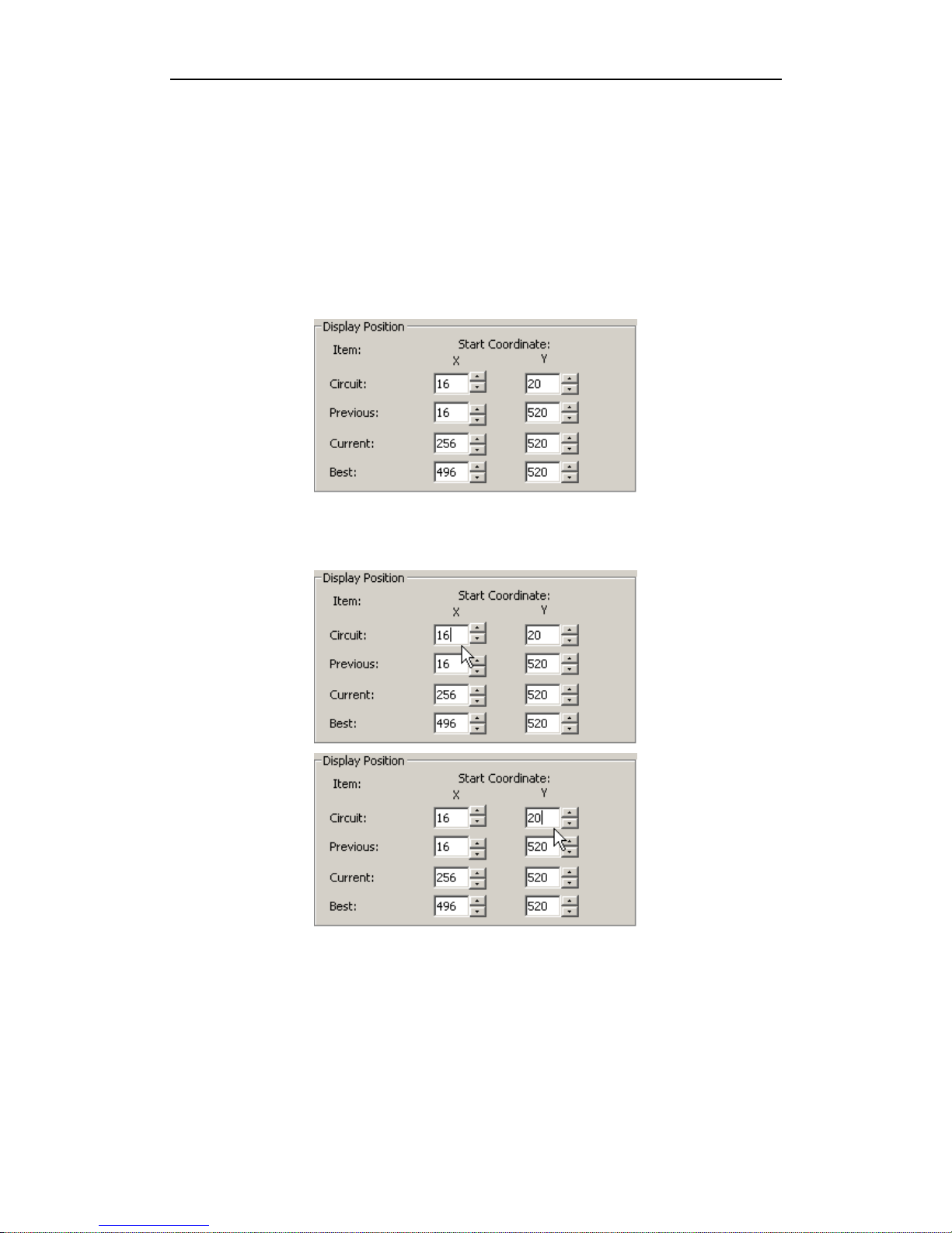
7.7.3 Adjust Position of Lap Timer Data on screen
You can adjust position of Lap Timer data on screen to fit different requirement &
playback device.
You can adjust the position of all Lap Timer data item.
Select item of Lap Timer data that you want to adjust, and then set the value of X & Y
coordinate on input area.
The unit of X & Y coordinate is pixel; the value bound is 720x576 of PAL & 720x480
of NTSC video standard.
Repeat above process to configure all position that you want to set.
Page 56

Configure DR3 DVR
- 50 -
7.7.4 Connection
Simply connect the External Beacon Receiver into the Beacon jack on the DR3 and
point the External Beacon Receiver to the Beacon. The Lap Timer will start to work
when Beacon signal is detected.
7.7.5 Mask Time
The Mask Timer is the time interval that DR3 doesn’t response after the detection of
Beacon & Split Beacon signal. The default value is 10 sec. If the time interval of twice
signal from Beacon & any Split Beacon emitter is small than Mask Time that you set,
the second signal will be ignored by DR3.
When Split Beacon option be enabled, any Split Beacon emitter & standard Beacon
emitter will be as alike signal emitter.
7.7.6 Recording of Lap Time
The time of each lap is record in the DVR_xxx.txt file. The file will looks like:
Hostname
Team WORKGROUP
Sport Motor
Scene Security
Page 57
DR3 DVR User’s Manual
- 51 -
READY.. = 04:05.588
Summary:
Total Record Time: 04:05.588
* Lap Timer is not a standard function of DR3 standard version, it is optional only for special version.
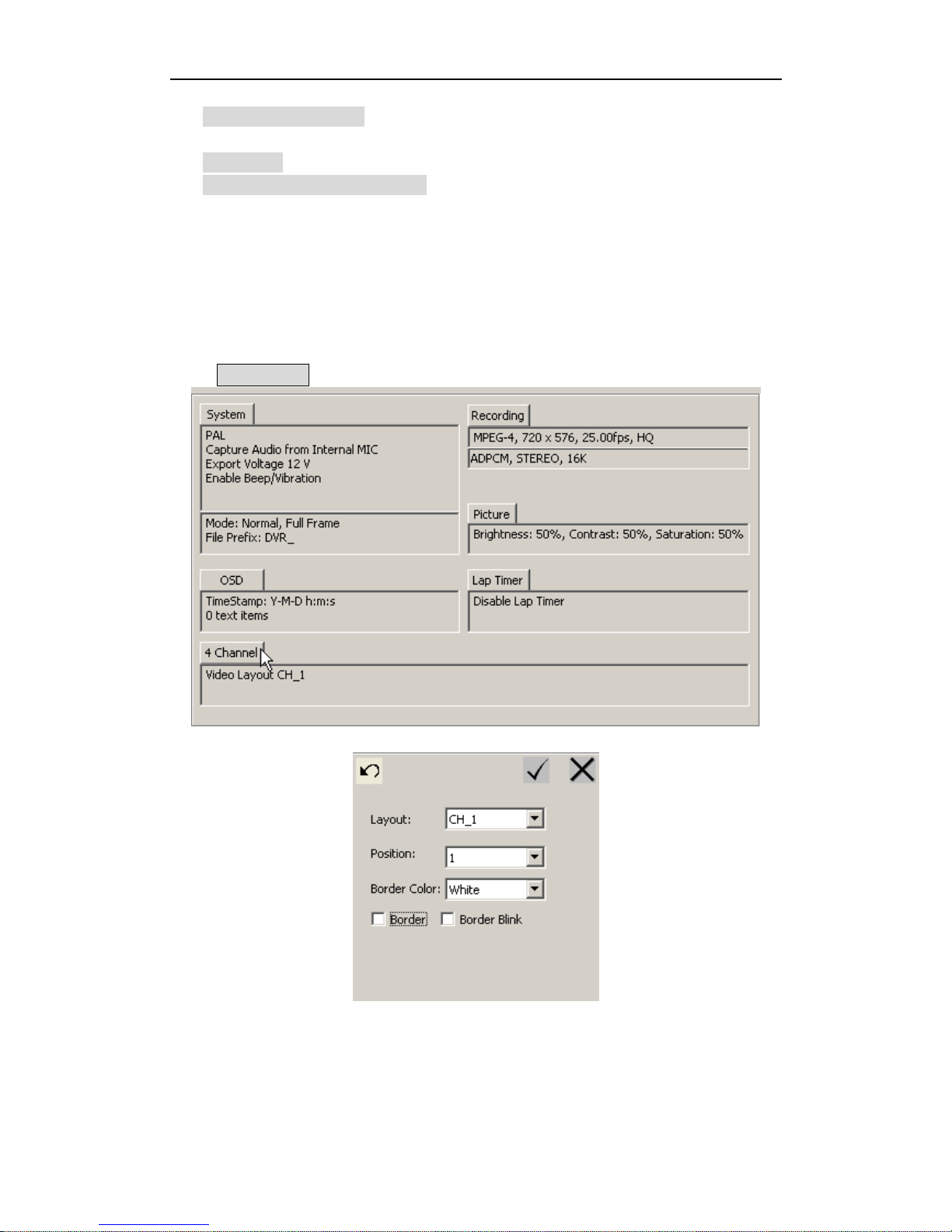
7.8 Configure 4-Channel DR3
The 4-Channel DR3 can connect four video inputs at the same time.
Click 4 Channel tab to configure 4-Channel DR3.
7.8.1 Video Input
You can select 1, 2, 3 or 4 channel video inputs at the same time, and record these video
in the same recording video.
Page 58
Configure DR3 DVR
- 52 -
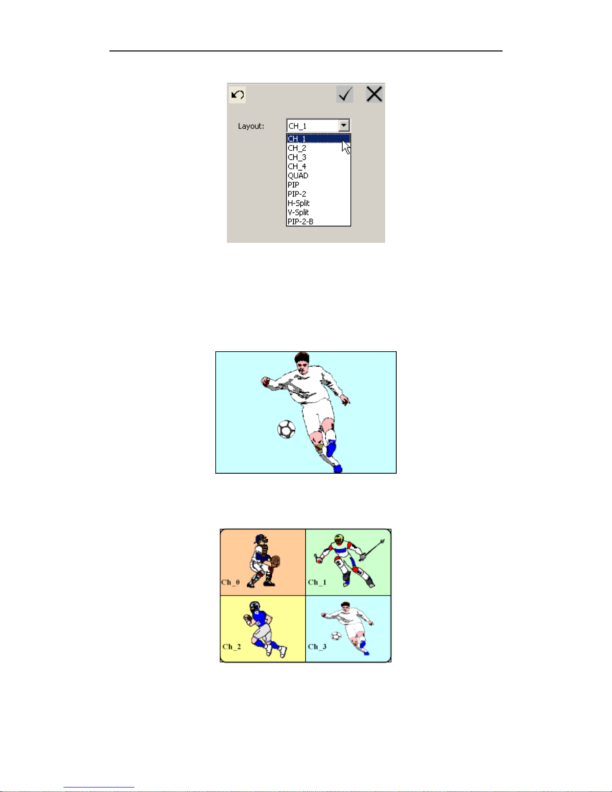
In the 4 Channel area, pull down menu of Layout to select the video input source,
amount of video inputs and video input arrange method.
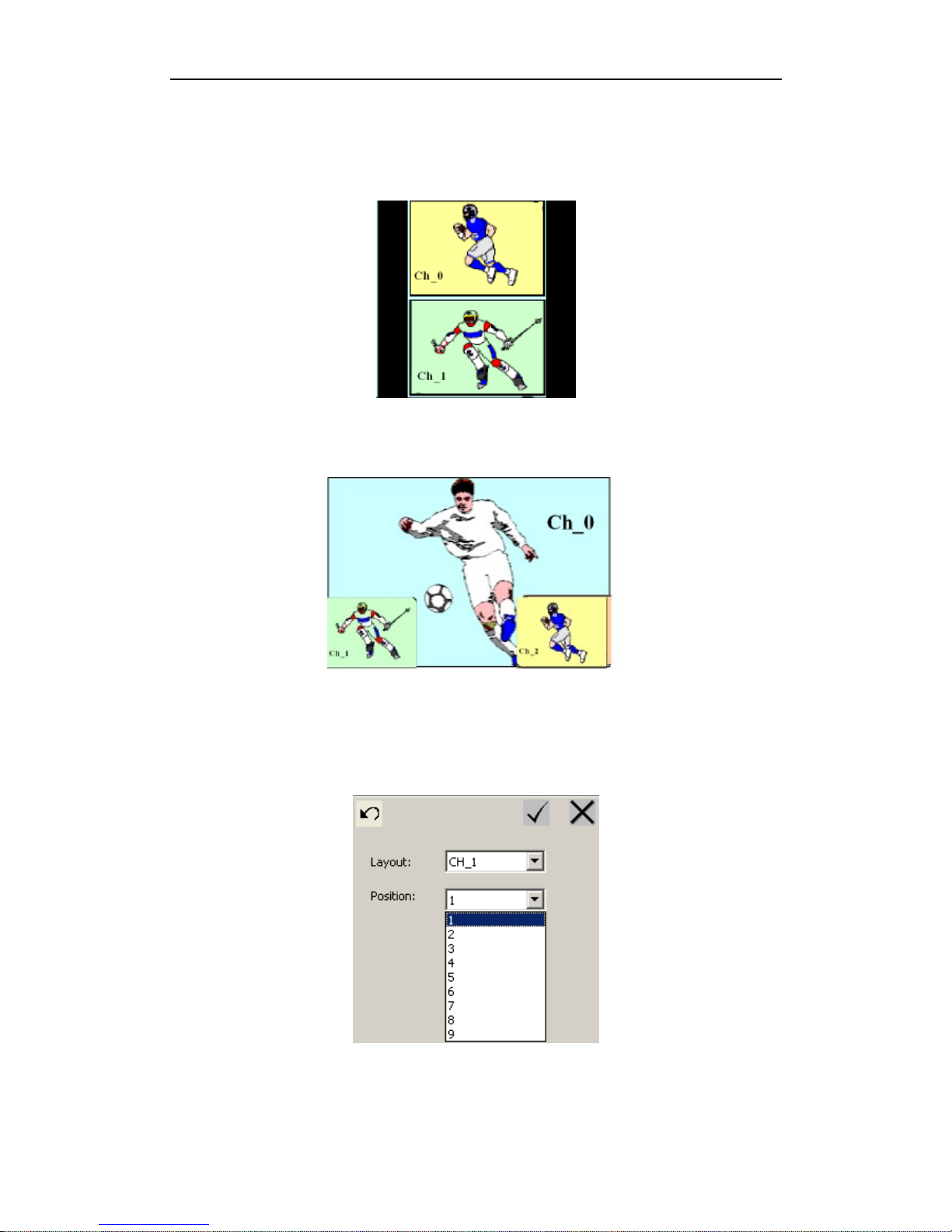
The CH_1, CH_2, CH_3 & CH_4 item mean video in 1 to video in 4 inputs are
selected, this is for 1 channel recording, and you can select any video input that you
want to record from.
If you want to record 4 channel video at the same time, please select QUAD. The
recorded video will include 4 channel videos in one video file.
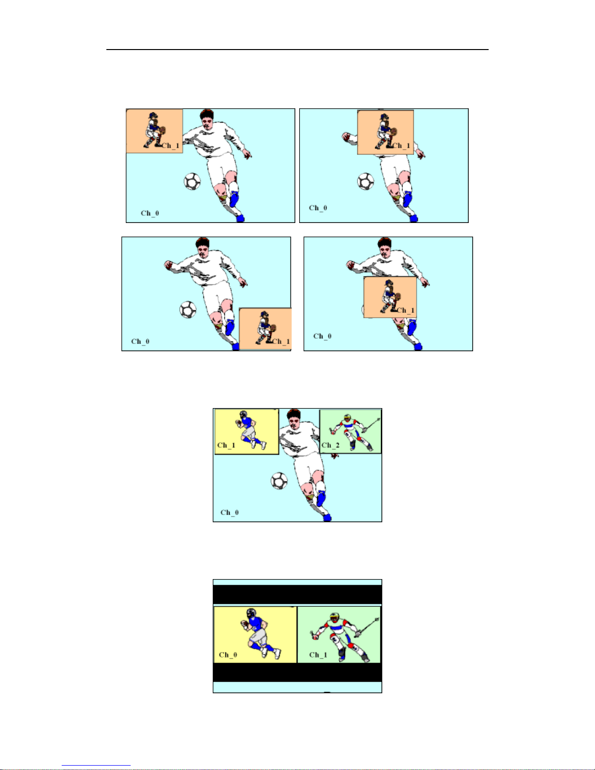
PIP item is for 2 channel video inputs at the same time, the 2 channel videos will be
recorded in one video file at the same time.
Page 59
DR3 DVR User’s Manual
- 53 -
PIP mode supports nine different position beforehand, please consult the
Picture-In-Picture (PIP) chapter for more details.
PIP-2 item is for 3 channel video inputs at the same time, the 3 channel videos will be
recorded in one video file at the same time.
H-Split item is for 2 channel video inputs at the same time, the 2 channel videos will be
recorded in one video file. H-Split item means the 2 channel video inputs array in
recording video file horizontally (Left & Right).
Page 60
Configure DR3 DVR
- 54 -
V-Split item is for 2 channel video inputs at the same time, the 2 channel videos will be
recorded in one video file at the same time. V-Split item means the 2 channel video
inputs array in recording video file vertically (Top & Button).
PIP-2-B item is another arranges method for 3 channel video inputs at the same time,
the 3 channel videos will be record in one video file at the same time.
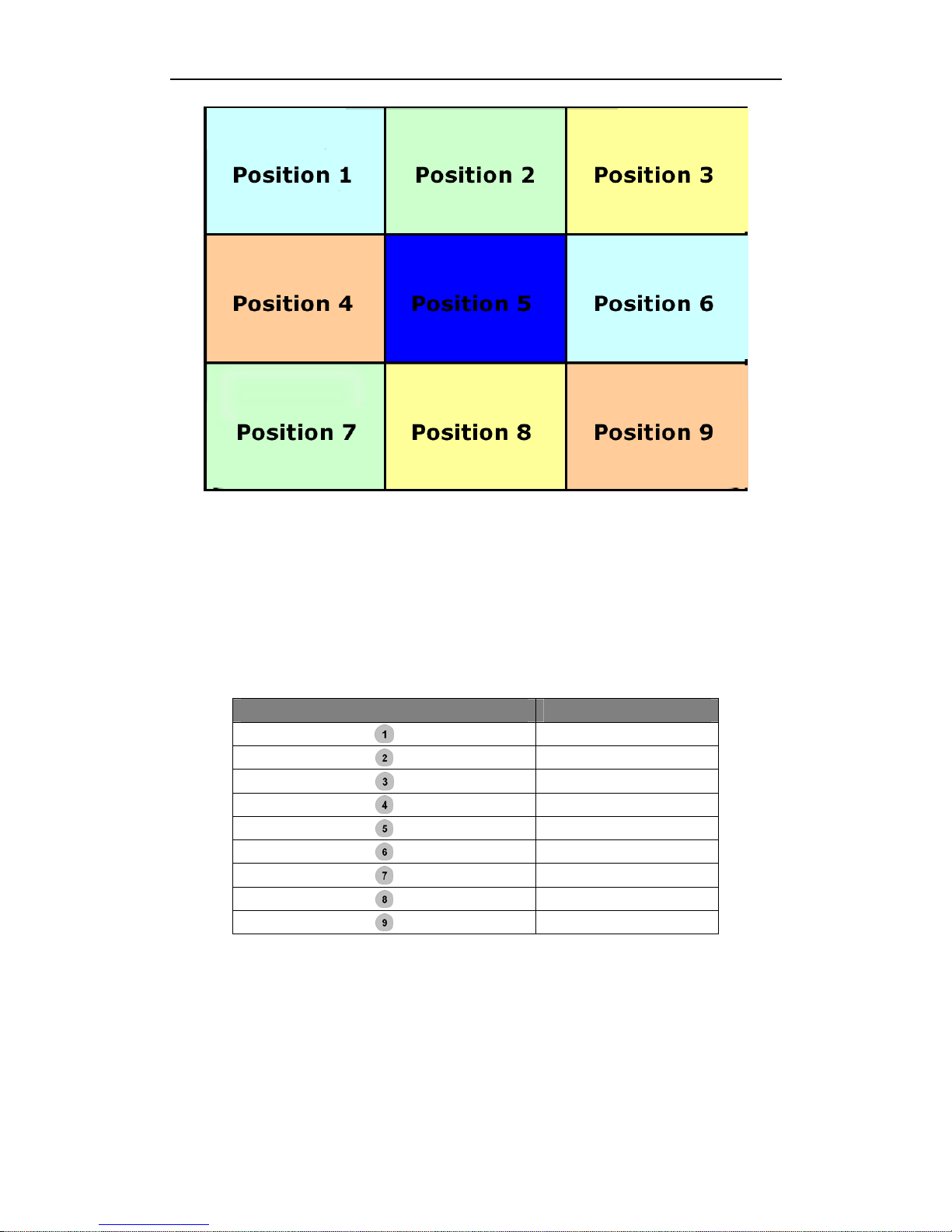
7.8.2 Picture-In-Picture (PIP)
You can configure any position for PIP recording video, it has nine different positions,
and you can select any position for your requirement from Position option.
You can configure or switch the array method of Picture-In-Picture via the DR3
Desktop & IR remote controller.
Page 61
DR3 DVR User’s Manual
- 55 -
The numeric keys on the IR remote controller is can be programmed with 9 array
methods of Picture-In-Picture, you can configure it & select any one array method as
your default array using the DR3 Desktop.
You can switch the array method using the numeric keys on the IR remote controller
directly when you record the video using the 4 Channel DR3. The numeric keys 1~9 is
controls the 9 items in the Position pull down menu.
Numeric Key on IR remote Controller Item in Position Menu
Position 1
Position 2
Position 3
Position 4
Position 5
Position 6
Position 7
Position 8
Position 9
Page 62
Configure DR3 DVR
- 56 -
7.8.3 The Border of Frame
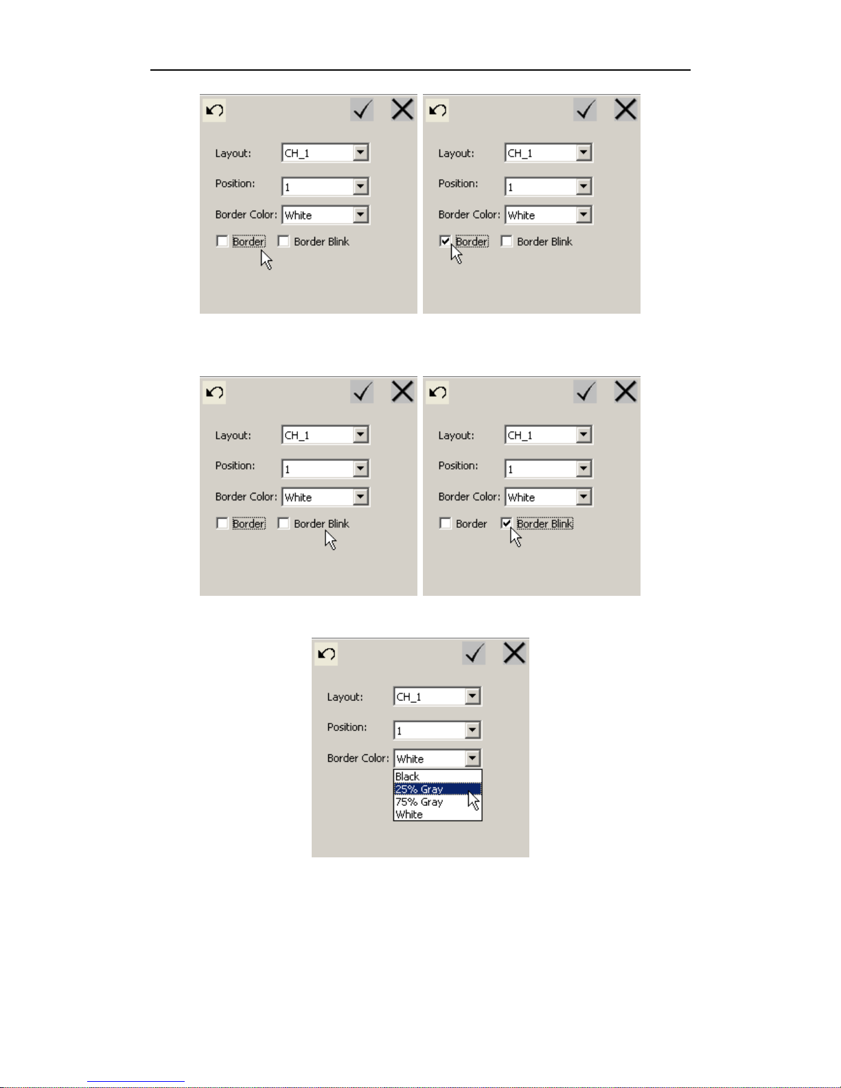
When you use 2 or 4 channel video inputs, you can enable/disable or select different
styles of frame for a better scene effect.
Switch on Border option to enable frame of video for Picture-In-Picture function.
Page 63
DR3 DVR User’s Manual
- 57 -
At the same time, you can switch on Border Blink option to enable frame of video
glint.
You can select 4 different styles of border frame.
7.8.4 Configuration Menu Output
4 Channel DR3 supports analog output to TV or Monitor, when you connect a TV or
Monitor to the Audio/Video Output, you can preview current video & the configure
menu.
Page 64
Configure DR3 DVR
- 58 -
NOTE: This option is only for 4-Channel DR3; it is not supported by 1-CH DR3.
7.9 Multi Profile Item Configuration
7.9.1 Configure & Save Multi-Profile Item
DR3 support multi-profile for different application, you can save 10 different
configurations into single configuration file, and then you can switch to anyone profile
between multi-profiles via LCD menu in your application.
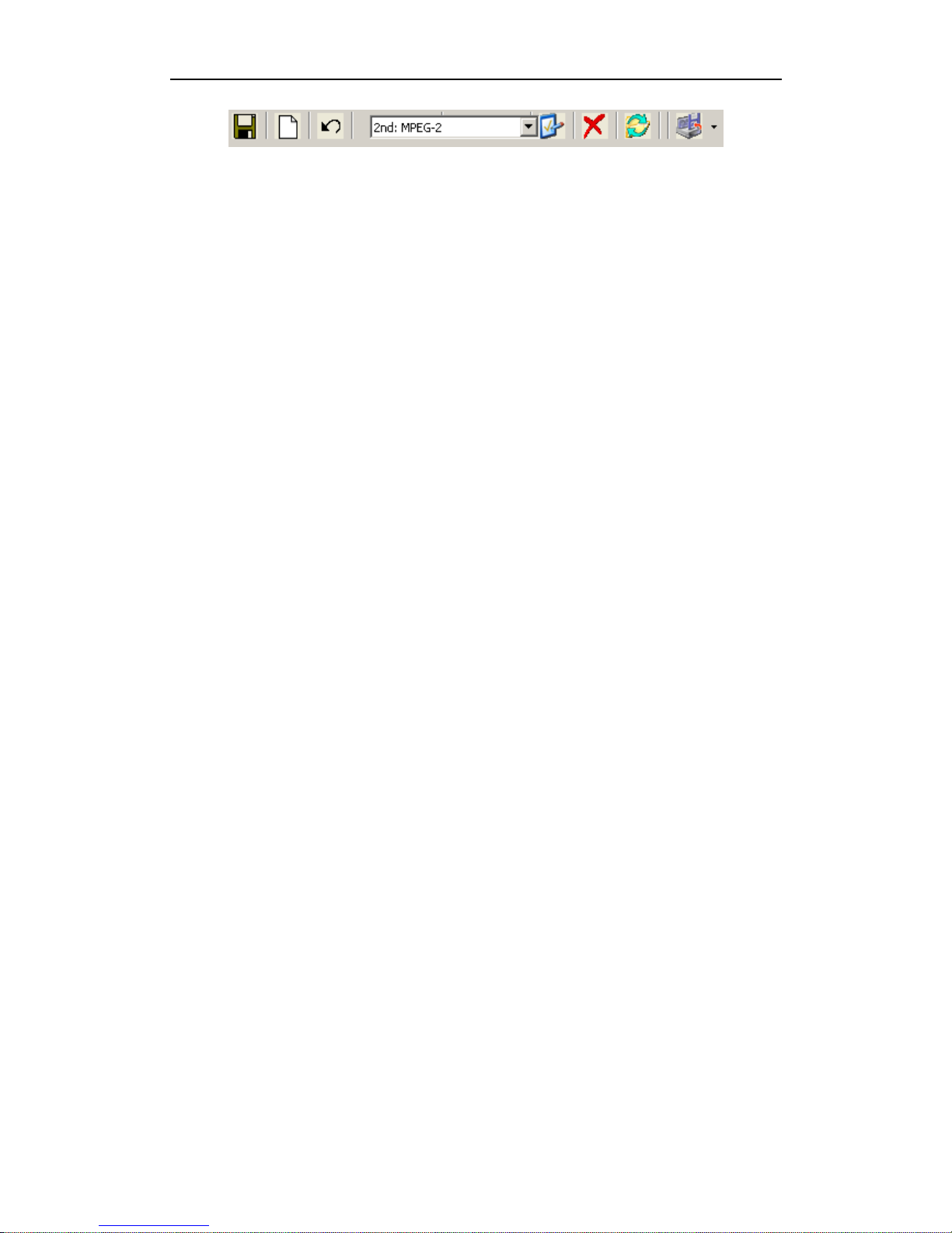
You can configure & save multi-profiles item using DR3 Desktop.
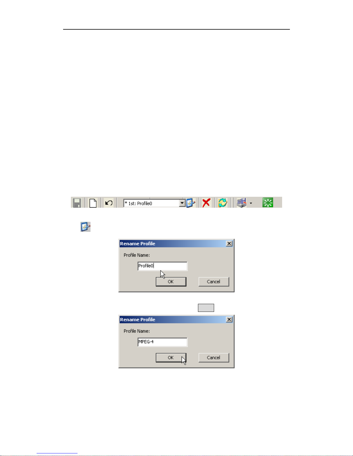
You can label every profile item using special name that be differentiated &
remembered easily.
You can create, rename, delete & save profile item using corresponding button on
button bar.
Click to name or name the first profile item.
Input new name of the first profile item, then click OK button to save it.
After you name or rename the first profile item, you can configure it that depends on
your application or requirement.
To configure DR3, please consult Configure DR3 chapter.
Page 65
DR3 DVR User’s Manual
- 59 -
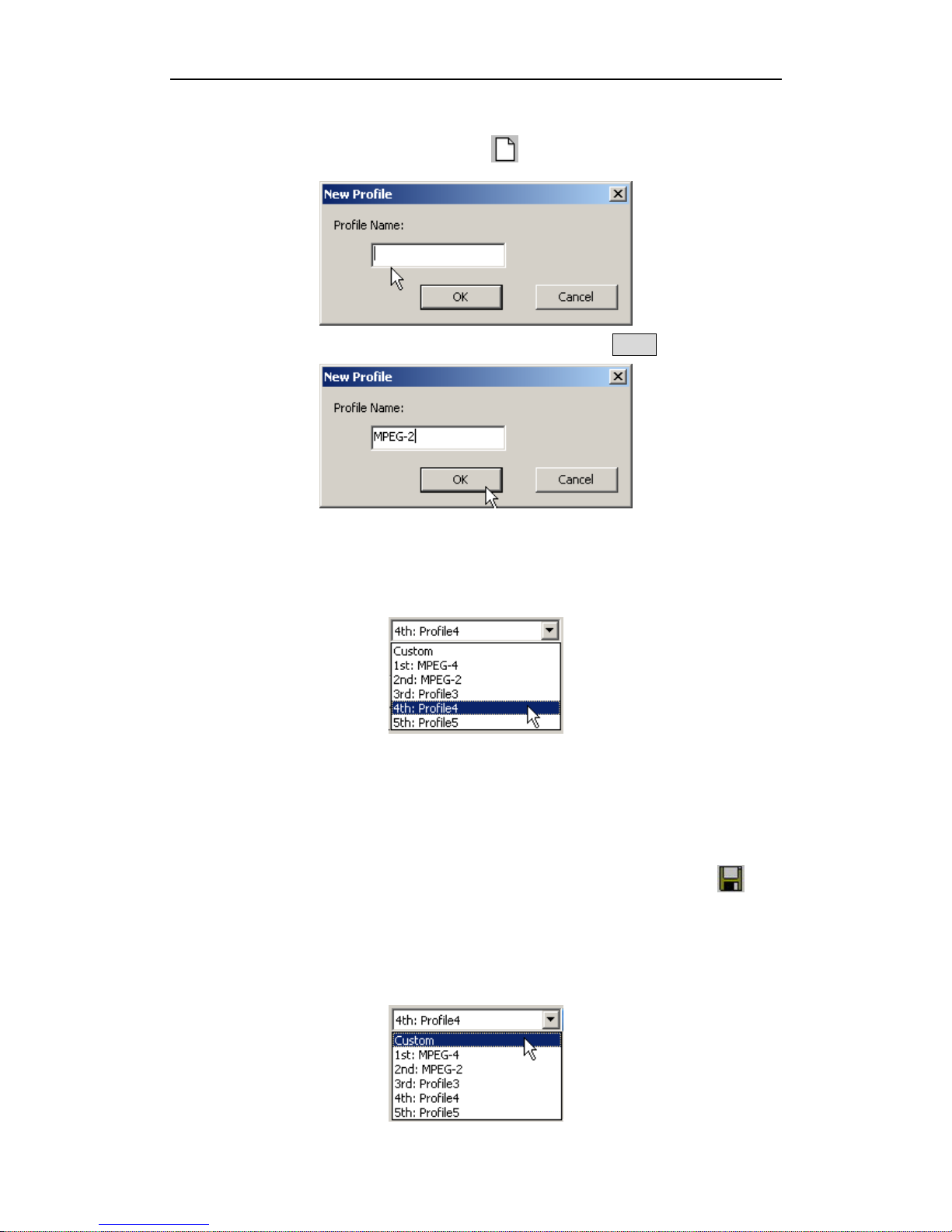
After you finish the first profile, please click to add new profile item.
Input name of the second profile item in name area, then click OK button to save it.
Now you can configure the second profile item as same as for the first profile item.
You can select anyone profile item from pull-down menu to configure it at anytime.
DR3 Desktop can keep maximum 9 profile items for a device at the same time.
Certainly, only one profile item is valid on once. You can switch one to another profile
item via LCD menu.
After you finish configuration for all profile items that you set, you can click
button to save all configuration.
The special Custom profile can’t be edit on DR3 Desktop, it only valid on LCD
menu.
Page 66
Configure DR3 DVR
- 60 -
You can change configuration in profile Custom on DR3 via LCD menu only, all
changes of configuration that you set on DR3 is active only when you set Custom as
default profile of DR3 via LCD menu.
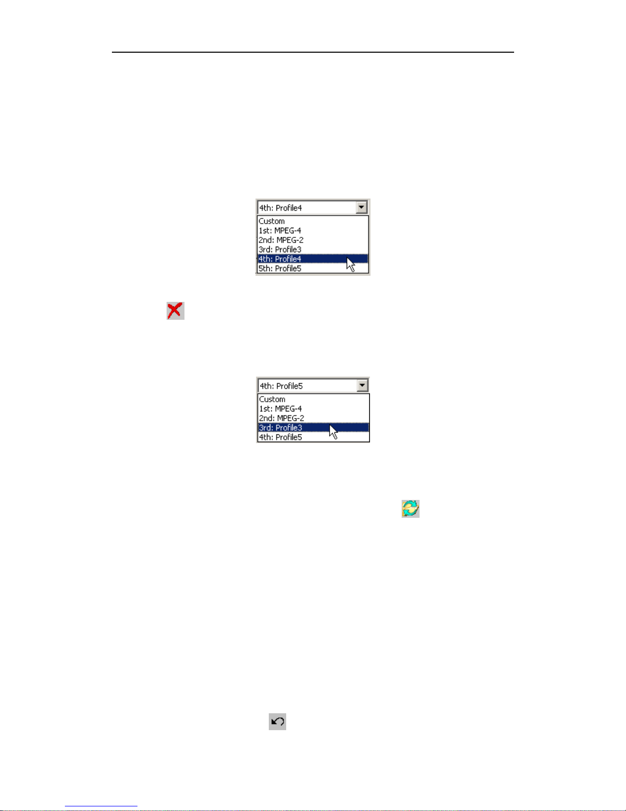
7.9.2 Delete Profile Item
If you want to delete anyone profile item, please select profile item that you want to
delete from pull-down menu.
Then click
to delete it.
After you delete anyone profile item, the profile item after it will ascend to current
arrange position.
7.9.3 Load Old Configuration
If you want to cancel all current configurations, you can click to reload the last
saved configuration, all changes that don’t be saved will be lost.
7.9.4 Reset selected profile item to default configuration
Sometime maybe you want to record different standard TV or video signal, you can set
anyone profile item to special video standard, the resolution, frame & correlative
internal parameter will be set to proper depend on the video standard, and the valid
coordinate range of Lap Timer data display will be adjusted to proper position
automatically.
You can set different profile item for different configuration, but sometimes you find
the special profile with many error or inapplicable configuration in profile, you can
select this profile, and then click to restore all configuration to default values.
Page 67
DR3 DVR User’s Manual
- 61 -
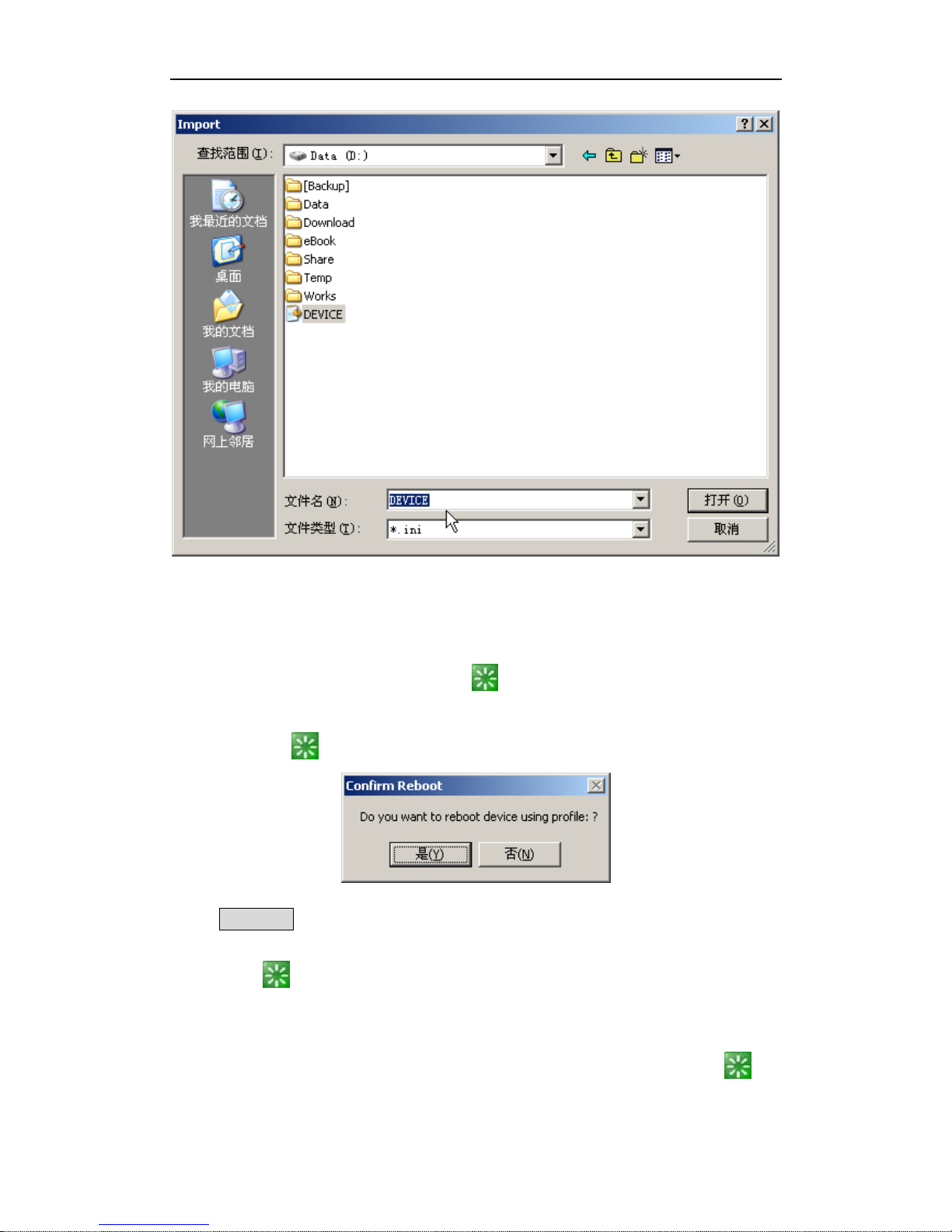
7.9.5 Backup & Restore Configuration File
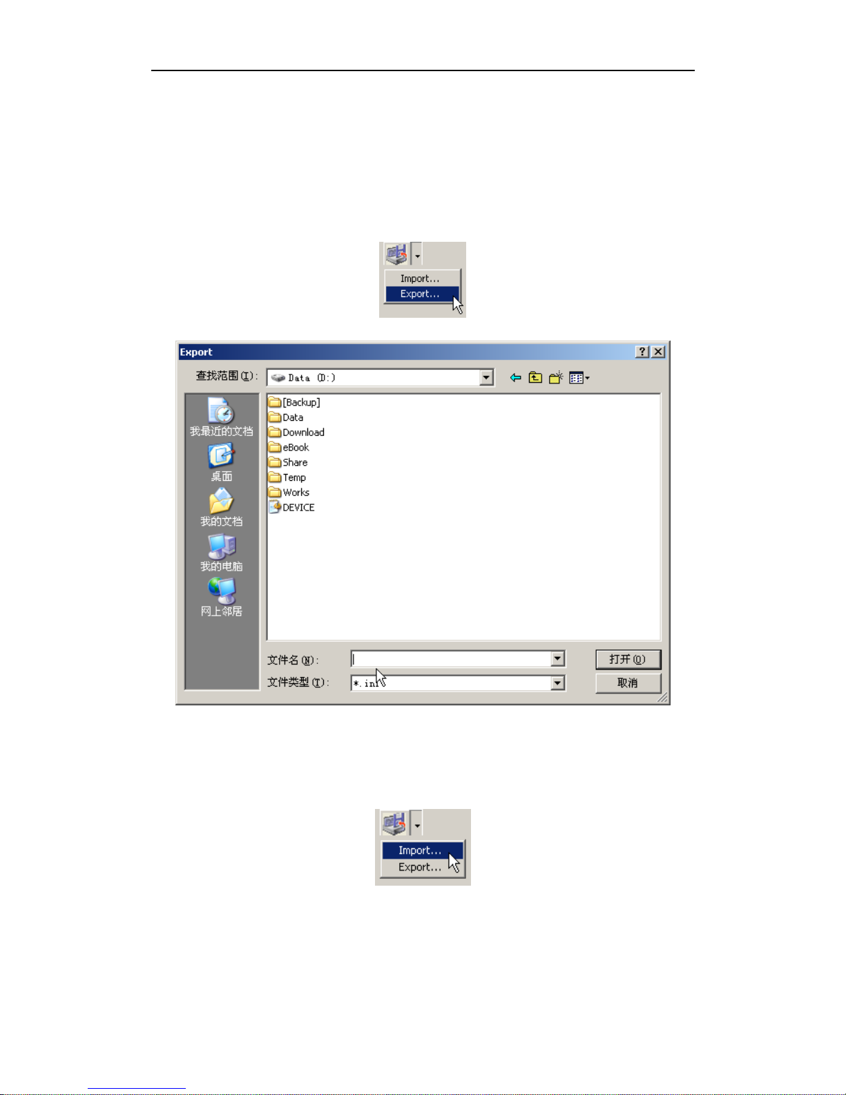
When you finish configuration for all profile item, to avoid correctly configuration be
lost or confused, after you save all configuration, you can export configuration file to
appointed disk or folder.
Certainly, you can reload configuration data that you backup previously to restore
DR3 to special configuration, import backup configuration data from disk or folder
that you saved backup.
Page 68
Configure DR3 DVR
- 62 -
7.9.6 Reboot DR3 after you finish configuration
After you finish all profile configurations, you can reboot DR3 using current profile
configuration via Desktop software, click to reboot DR3 immediately.
When you click to reboot DR3, system will prompt you to get confirm again.
Click Yes (Y) button to reboot DR3.
The Reboot function is valid only when you connect DR3 to PC via network
connection.
If you startup Desktop software via CF card that connected to PC, the Reboot
button will be disable.
Page 69
DR3 DVR User’s Manual
- 63 -
7.9.7 Switch Configuration Item
You can switch configuration item via LCD Menu during use DR3.
Page 70
Synchronize Video
- 64 -
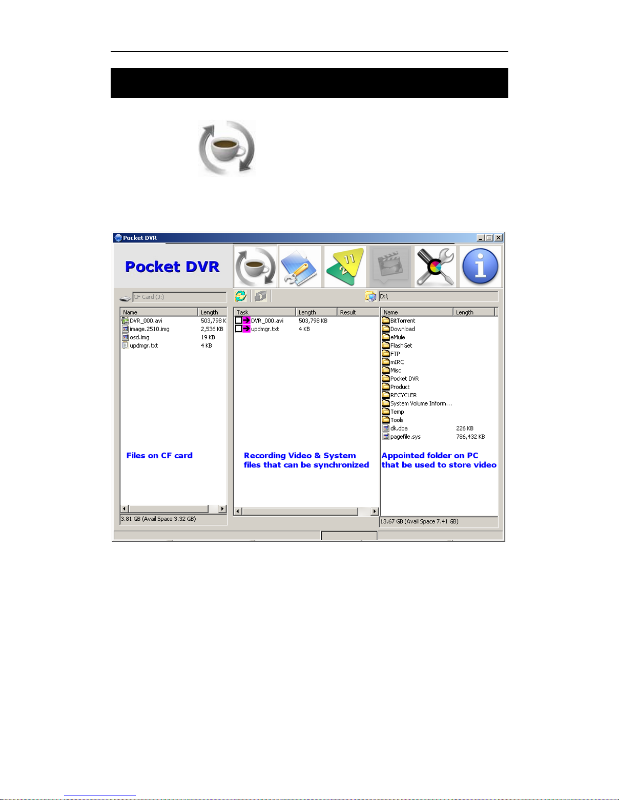
8. Synchronize Video between CF & PC
Click Sync button to synchronize the recording video between CF card &
PC.
Please select files that you want to synchronize on task column.
Page 71
DR3 DVR User’s Manual
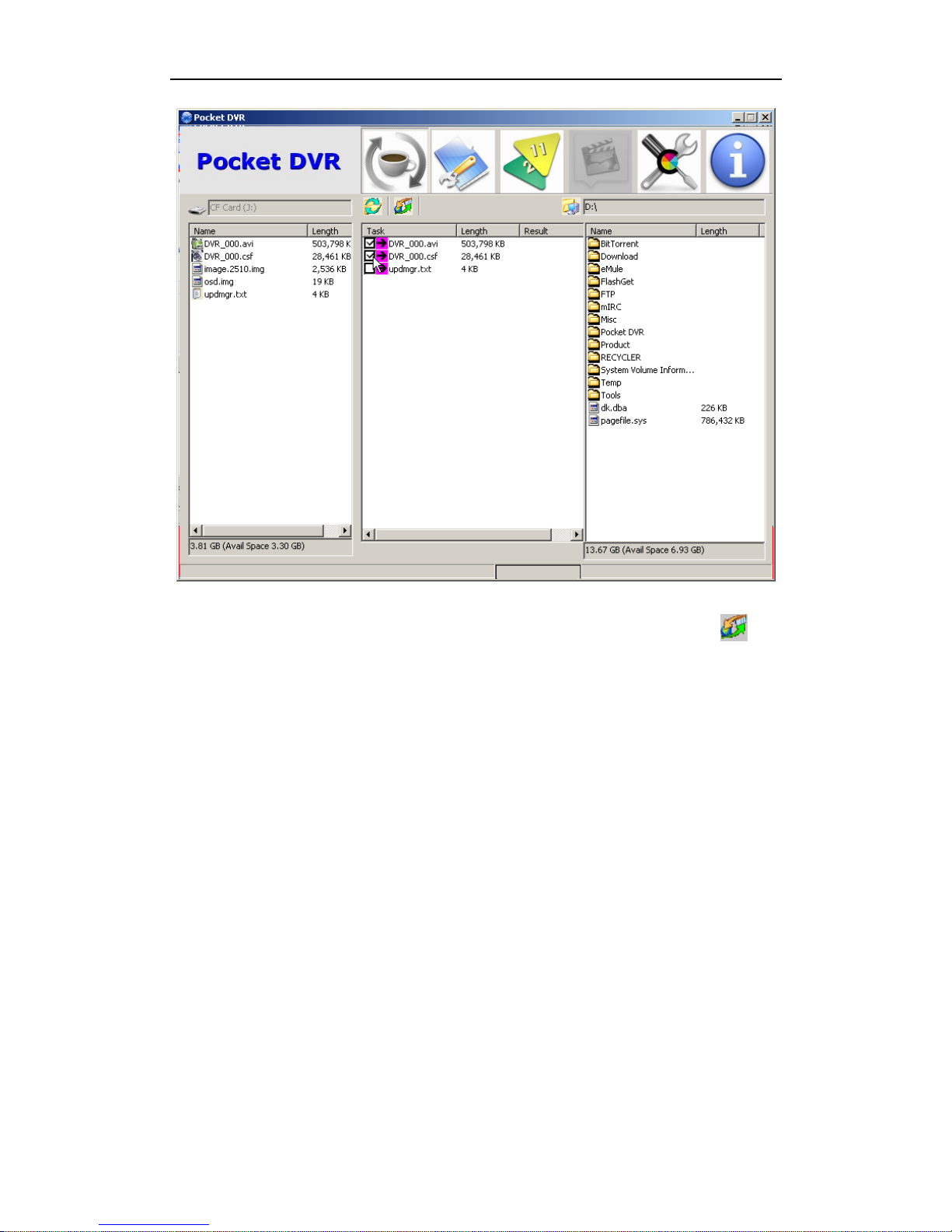
- 65 -
After you select all files that you want to synchronize, then click Sync button to
start synchronization.
Page 72
Synchronize Video
- 66 -
Page 73
DR3 DVR User’s Manual
- 67 -
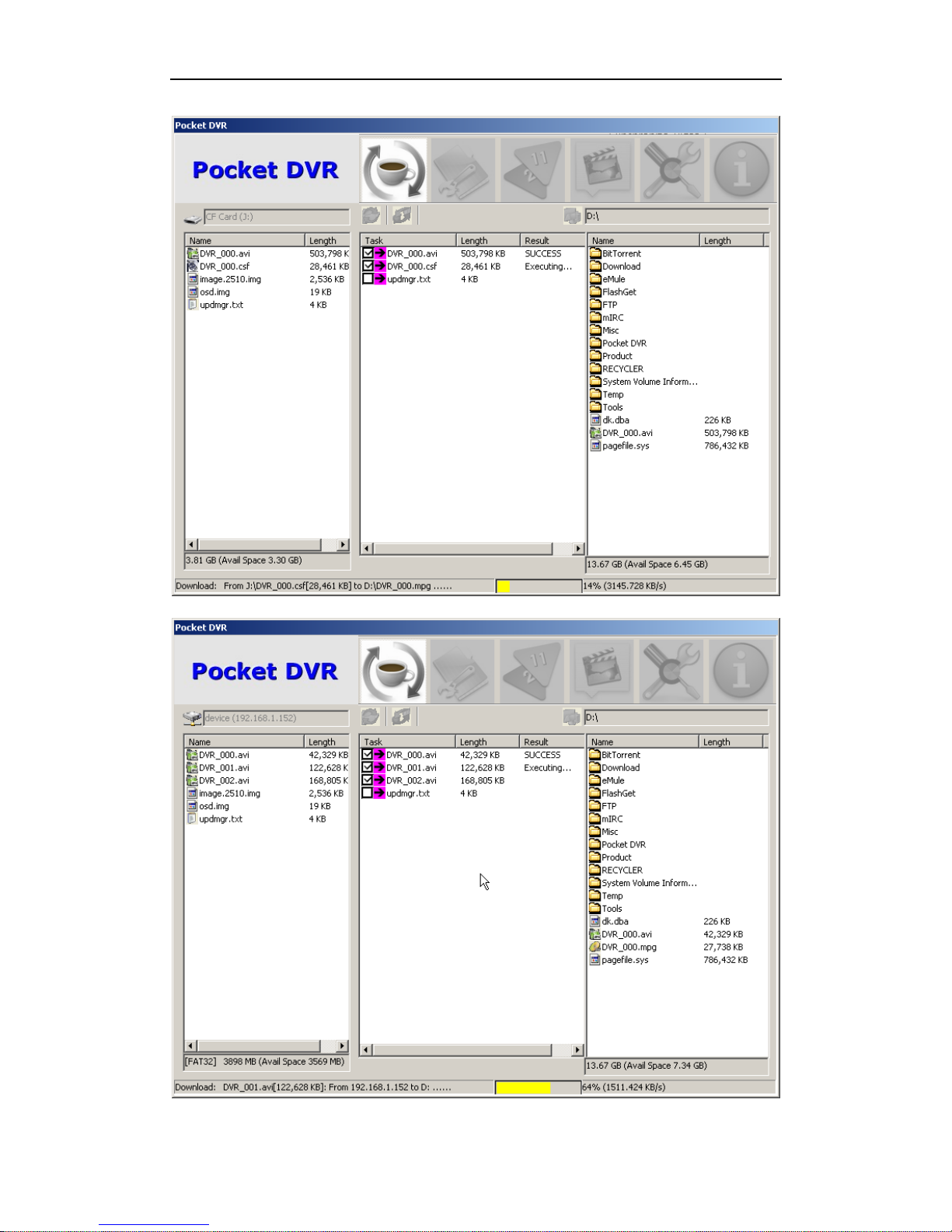
In task column, the result item will display status of files.
If you startup Desktop software via CF card, Desktop will display CF card on PC on
button status bar, if you connect DR3 to PC via LAN connection, the IP address will
be display on button status bar.
Executing… means the files being synchronizing, SUCCESS means the files had been
synchronized successfully.
When a file being synchronizing, the yellow status bar will display on the button.
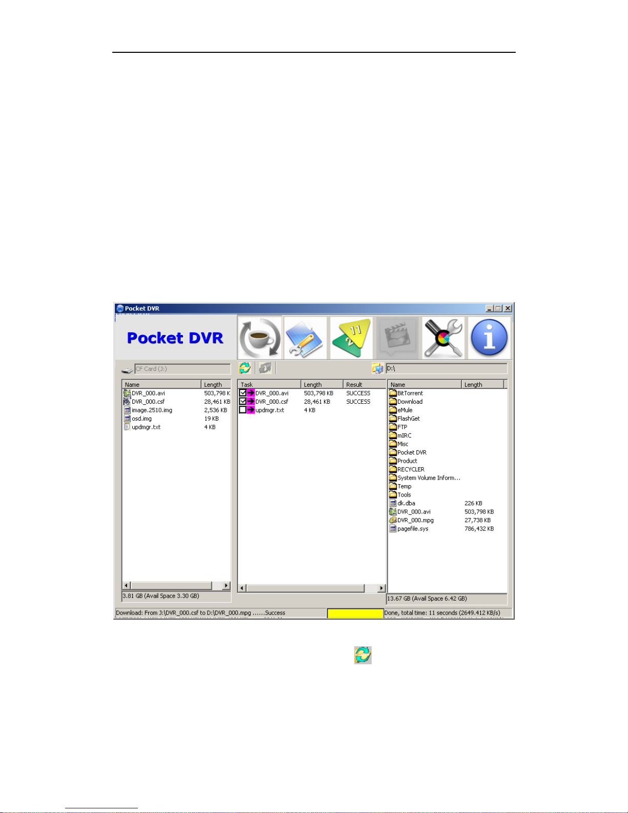
After all files are synchronized successfully, files will be synchronized to the folder on
PC, you will find these files on the working folder column.
After synchronization, you can click refresh button to refurbish task column.
Page 74
Synchronize Video
- 68 -
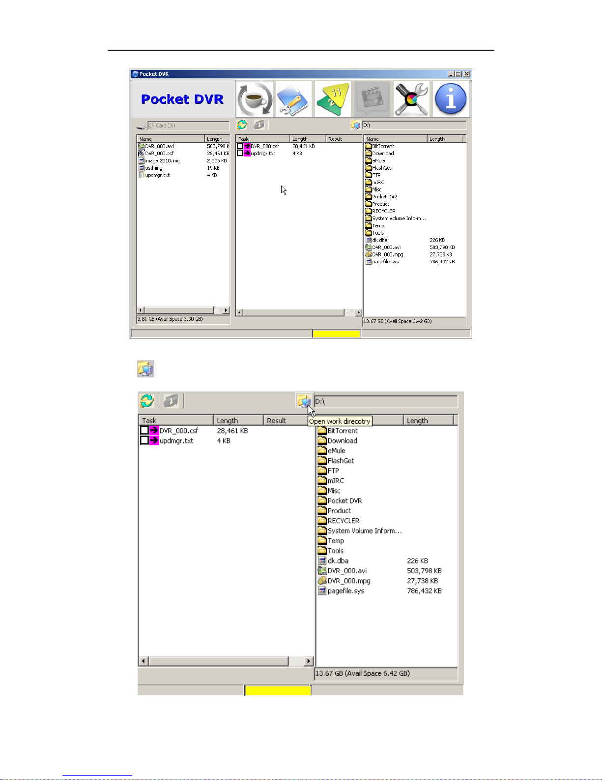
Click to open working folder on PC.
Page 75
DR3 DVR User’s Manual
- 69 -
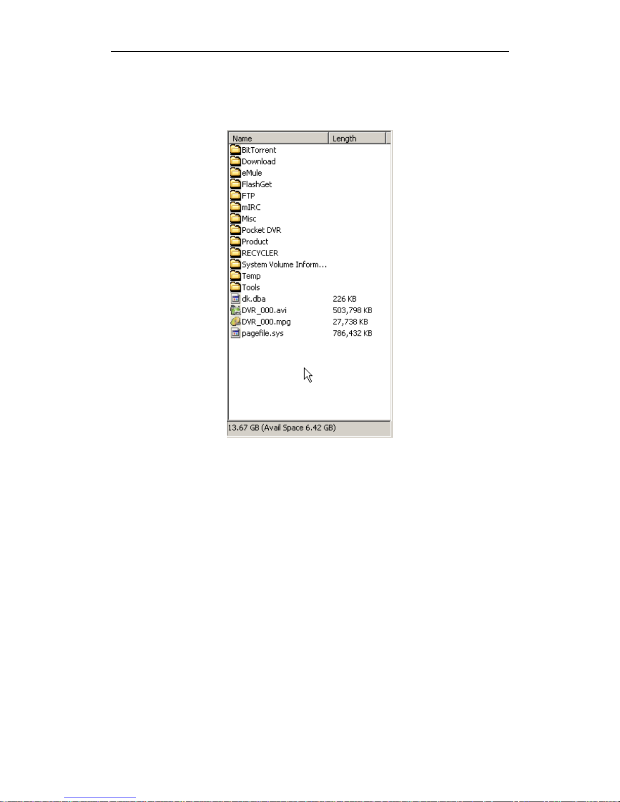
In synchronization, the .csf MPEG-2 recording file will be converted to standard
MPEG-2 video automatically.
Page 76
MPEG-2 Converter
- 70 -
9. MPEG-2 Converter
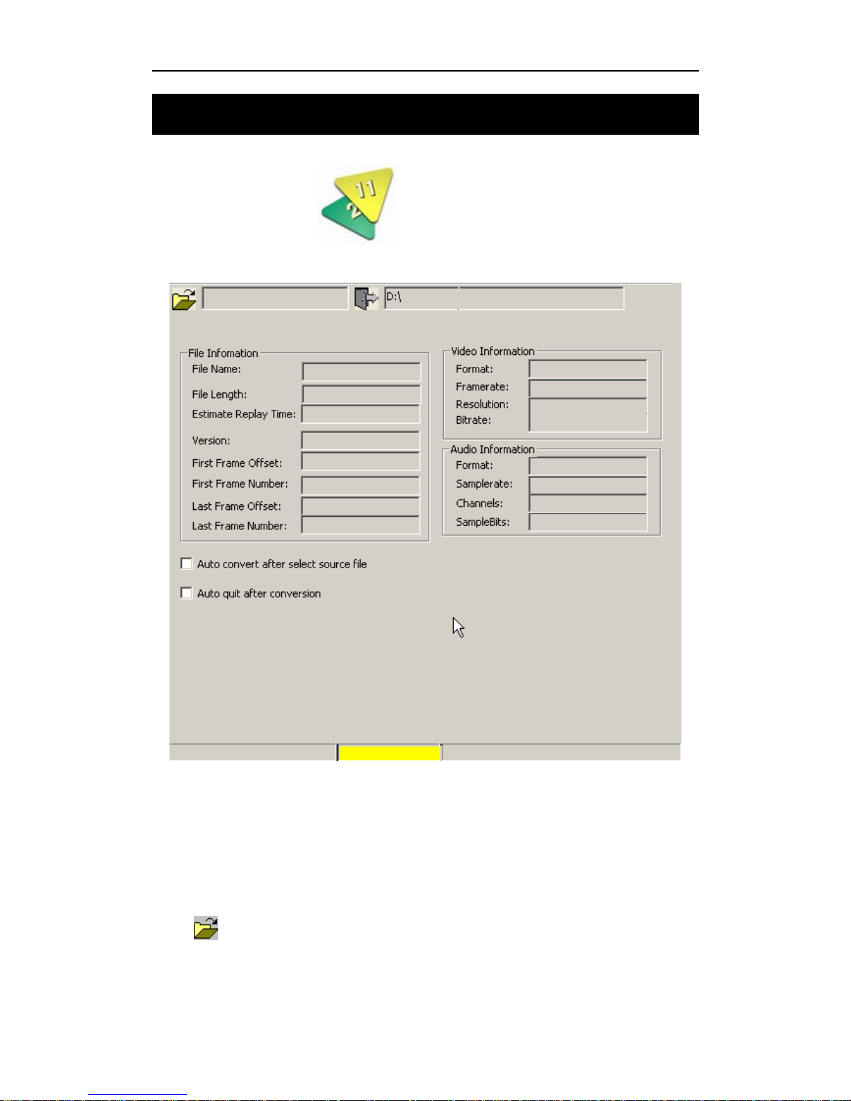
Click Conversion button to render MPEG-2 recording video manually.
Recorded MPEG-2 file have to be converted to standard MPEG-2 video for later video
replay, edit & burn. The conversion of MPEG-4 is not required.
Sometime maybe you copy many .csf MPEG-2 recording files to PC, and then convert
them manually.
Click
to open working folder on PC that you save .csf MPEG-2 files.
Page 77
DR3 DVR User’s Manual
- 71 -
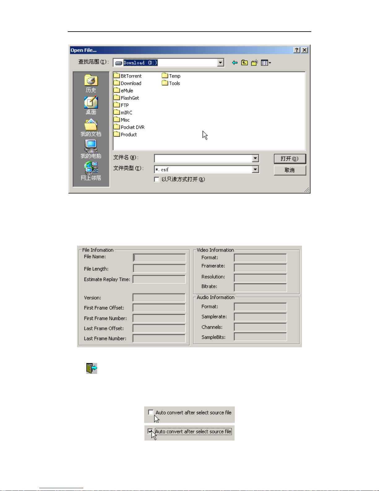
Then select .csf file that you want to convert.
After you select the source file to convert, detailed information of the recorded
MPEG-2 video will be displayed.
Click to convert the .csf file that you select.
The file can be converted automatically after you select the file if you enable
automatically convert option.
Page 78

MPEG-2 Converter
- 72 -
For better performance of conversion, it is recommended that source file is on the CF
card in a card reader and target file is on the hard disk.
Page 79
DR3 DVR User’s Manual
- 73 -
10. Advanced Configuration
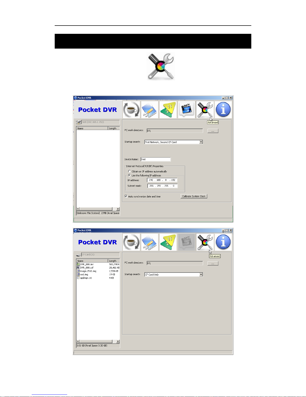
Click Advanced Configuration button to configure system
environment.
Page 80
Advanced Configuration
- 74 -
You can select working directory on PC to as synchronize folder, set search sequence
for startup, change network configuration of DR3, sync date & time, and calibrate
DVR system clock.
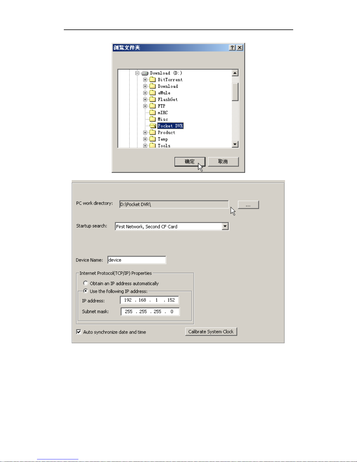
10.1 Change Synchronize Folder
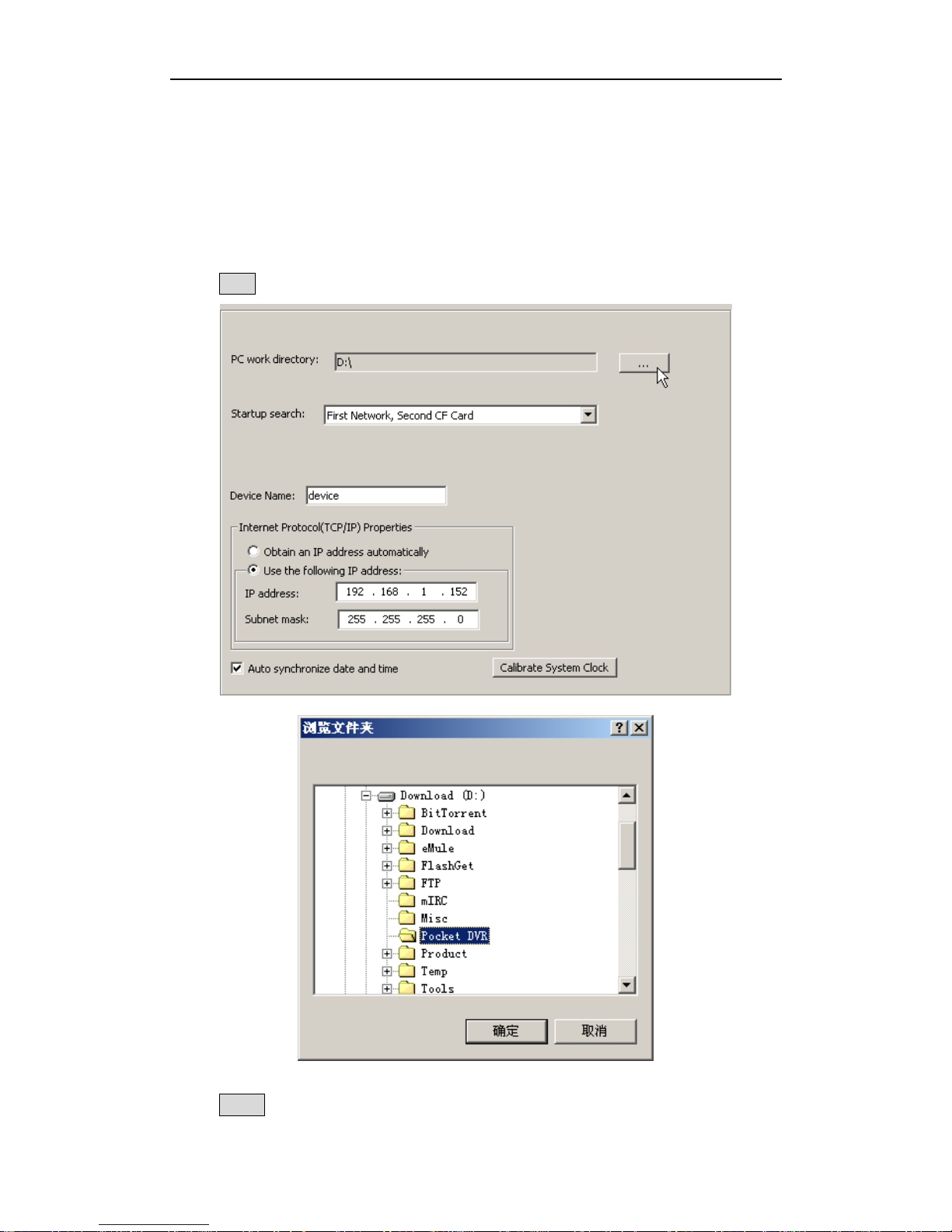
Click … button to select working directory on PC to as synchronize folder.
Click OK button to confirm your selection.
Page 81
DR3 DVR User’s Manual
- 75 -
10.2 Configure Desktop Startup Method
DR3 Desktop will detect Network connection between DR3 & PC in first, if Desktop
can’t detect valid network connection, then it will detect CF card that you want to used
in DR3, please connect CF card to PC via card reader before you start DR3 Desktop if
you don’t want to connect DR3 to PC via LAN.
Page 82
Advanced Configuration
- 76 -
The default sequence of DR3 Desktop is detecting valid network connection between
DR3 & PC in first, then detect CF card if it can’t find any valid net work connection.
Certainly, you can change the default detection method in DR3 Desktop software.
10.2.1 Startup Desktop software via Network Connection
Connect Network Sync cable that in package between DR3 & PC or switch/HUB in
first, then double click to start-up DR3 Desktop.
DR3 Desktop will search valid network connection.
After DR3 Desktop detects valid network connection, it wills start-up successfully.
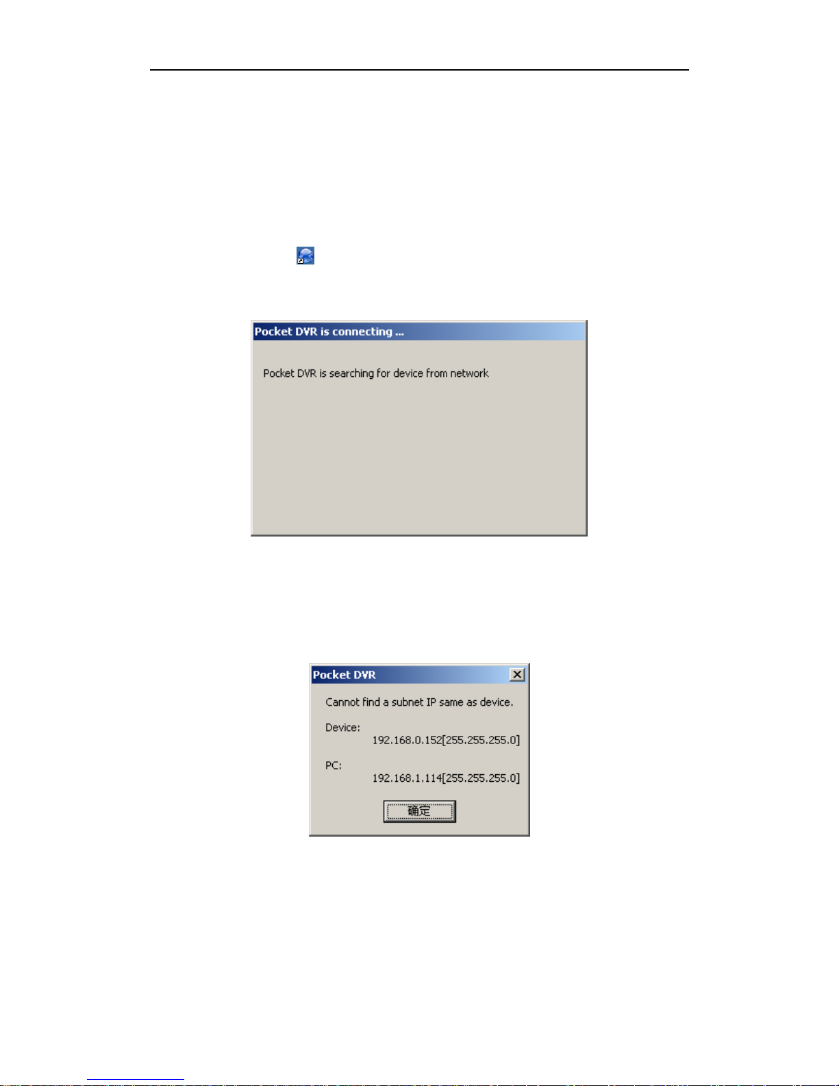
The default IP address of DR3 is 192.168.0.152, please ensure your PC on same IP
segment for first connection. If your PC & DR3 with different IP address segment,
Desktop software will prompt you.
You can change IP address of your PC to same IP segment with DR3, such as
192.168.0.100, and then restart Desktop software again.
After you startup Desktop software successfully, you can change IP address of DR3 to
same IP segment with your local LAN.
Page 83
DR3 DVR User’s Manual
- 77 -
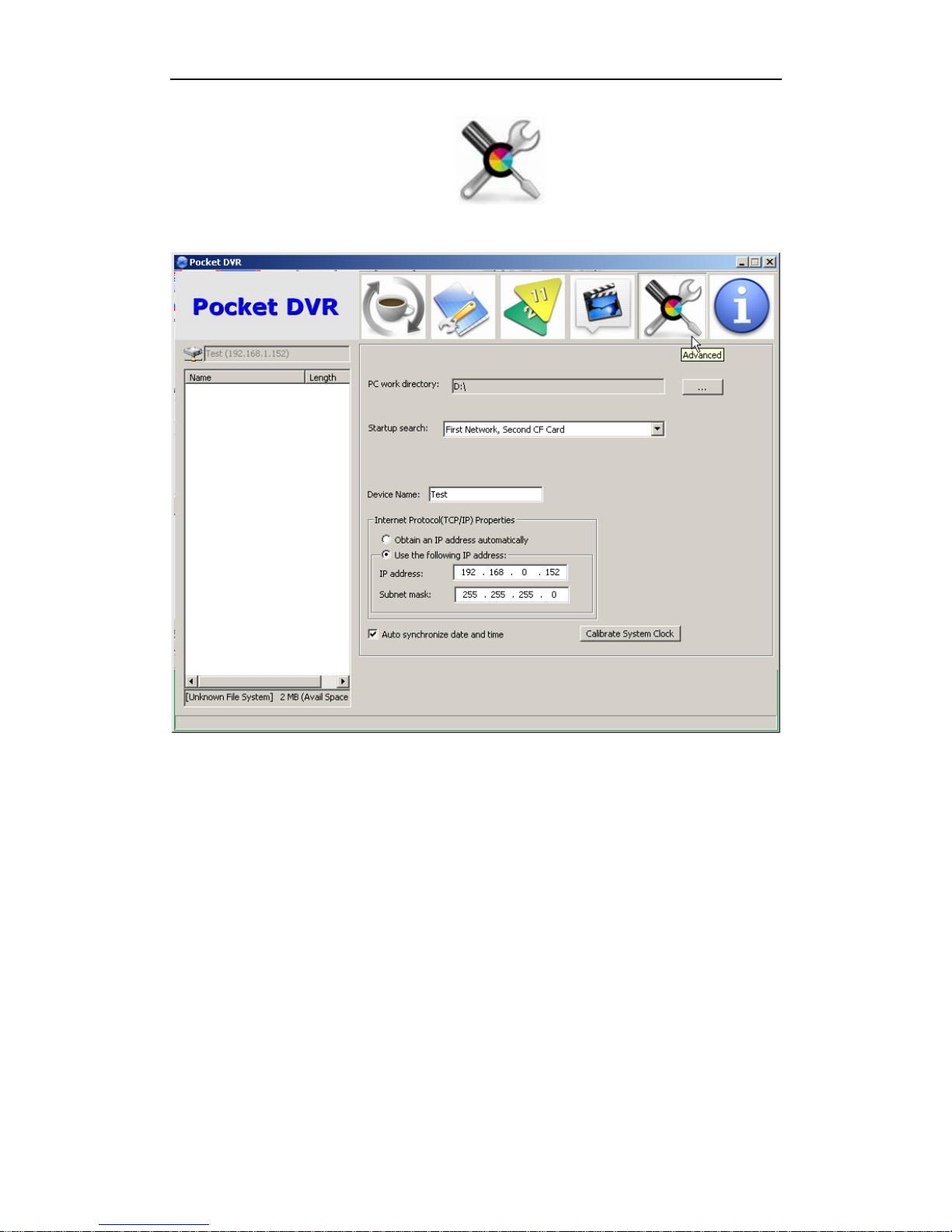
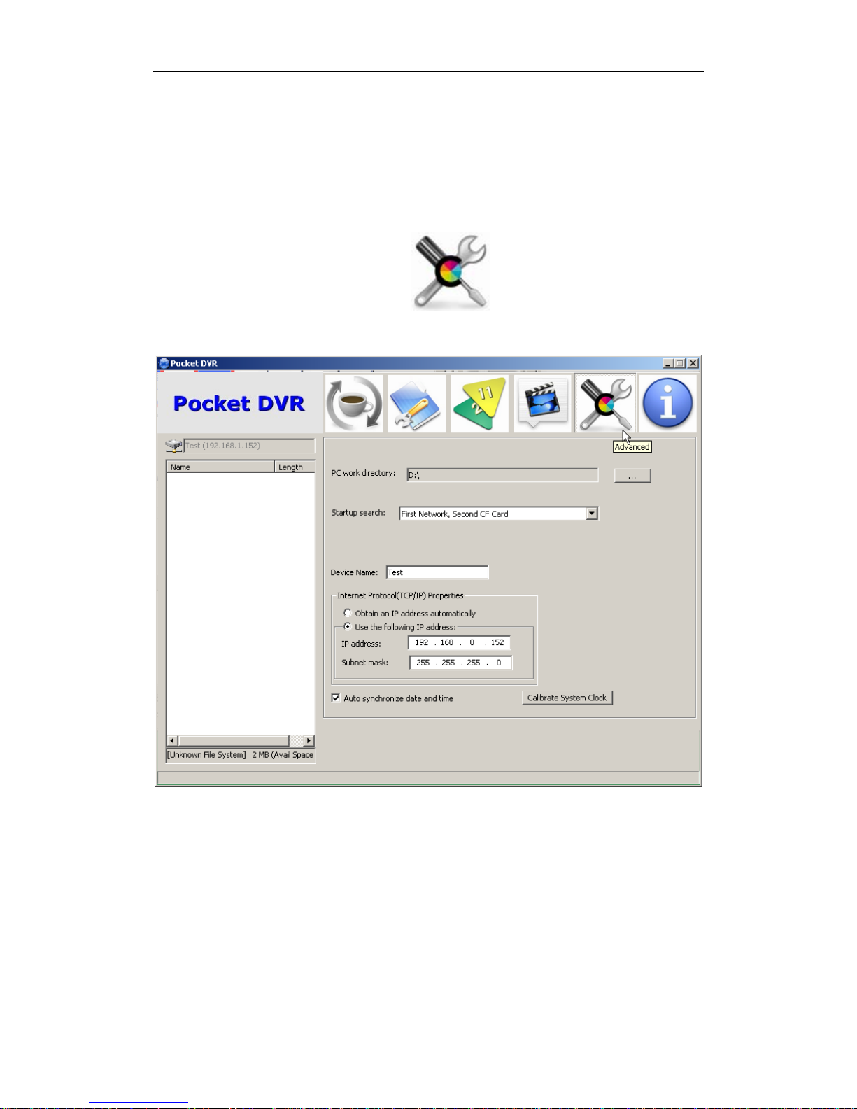
Click Advanced Configuration button to configure network
environment of DR3 connection.
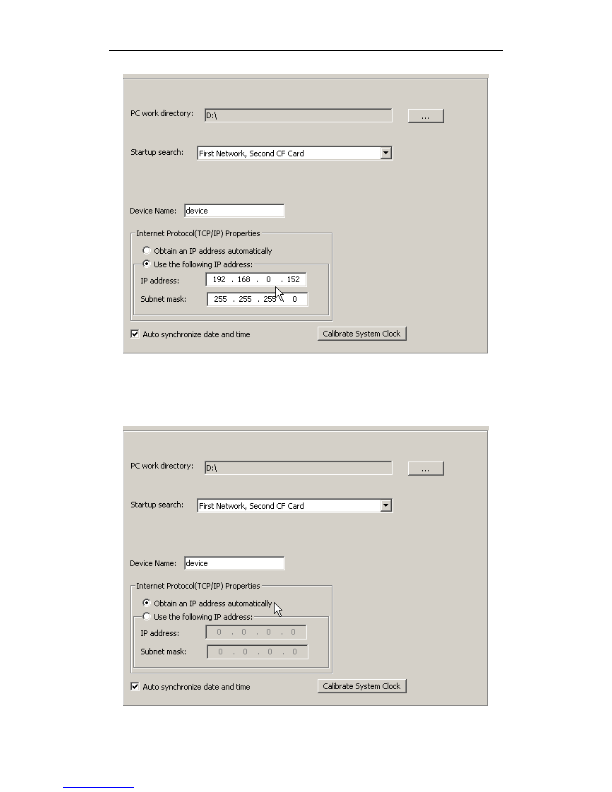
You can change IP address of DR3 manually.
Page 84
Advanced Configuration
- 78 -
Or you can let DR3 obtain IP address from DHCP server on your local LAN if you
connect DR3 to router or switch. But please notice, the router or switch that be
connected DR3 must support MDI/MDI-X connection.
Page 85
DR3 DVR User’s Manual
- 79 -
10.2.2 Startup Desktop software via CF card Connection
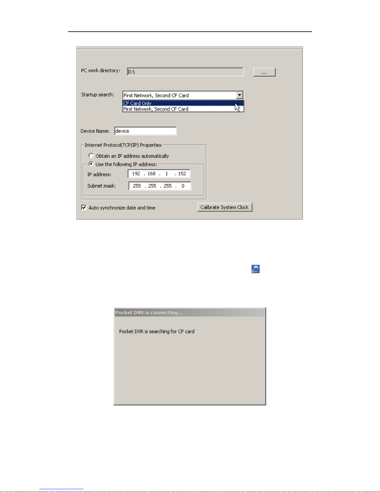
Change Startup Search option from default configuration to CF Card only, then you
can startup DR3 Desktop via CF card that connect to PC without network connection.
Click Advanced Configuration button to configure connection
configuration.
Then set Startup Search option to CF Card Only item.
Page 86
Advanced Configuration
- 80 -
After you configure it, you can startup Desktop software only via CF card without
network connection for the future.
Connect CF card to PC via card reader in first, then double click to start-up DR3
Desktop.
DR3 Desktop will search CF card on PC.
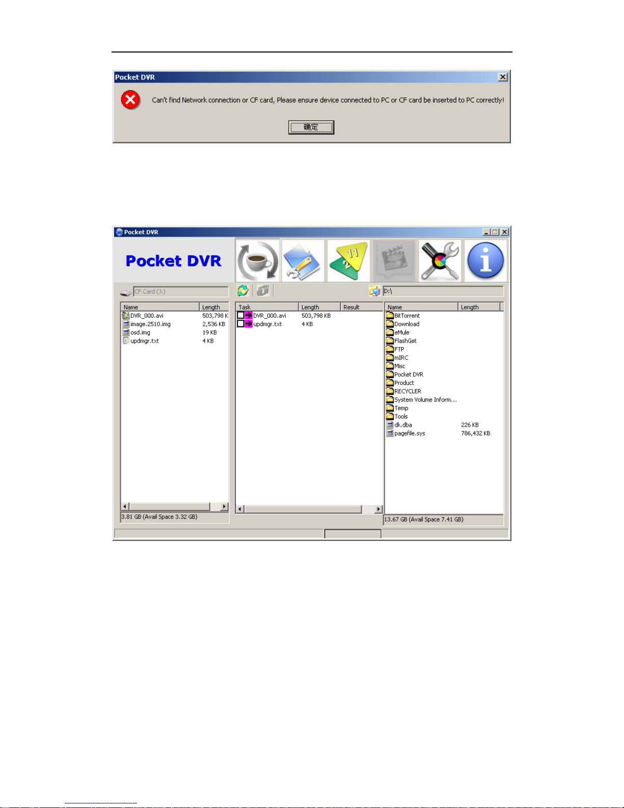
If CF card can’t be connected to PC correctly or no CF card be connected to PC, DR3
Desktop will display error message to prompt you connect CF card to PC correctly.
Page 87
DR3 DVR User’s Manual
- 81 -
If CF card that you connect to PC had been used in DR3 or be initialized by DR3
Desktop, DR3 Desktop will detect the DEVICE.INI file on the root directly of CF card,
and DR3 Desktop will start-up automatically.
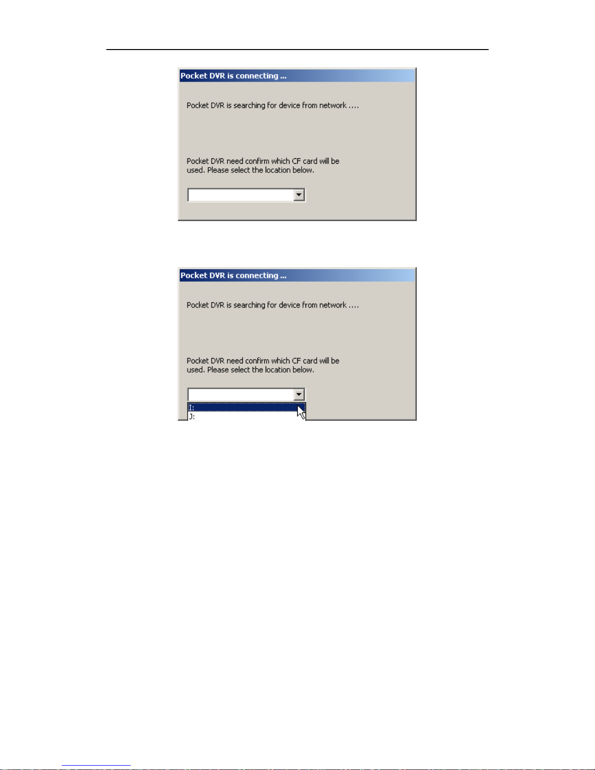
If DR3 Desktop detect a new CF card, system will prompt you select a correctly disk
that point to CF card.
Page 88
Advanced Configuration
- 82 -
After you select correctly disk, DR3 Desktop will initialize CF card and create
DEVICE.INI configuration file on root of CF card automatically.
Once DR3 Desktop finished initialization, it wills start-up automatically.
Page 89
DR3 DVR User’s Manual
- 83 -
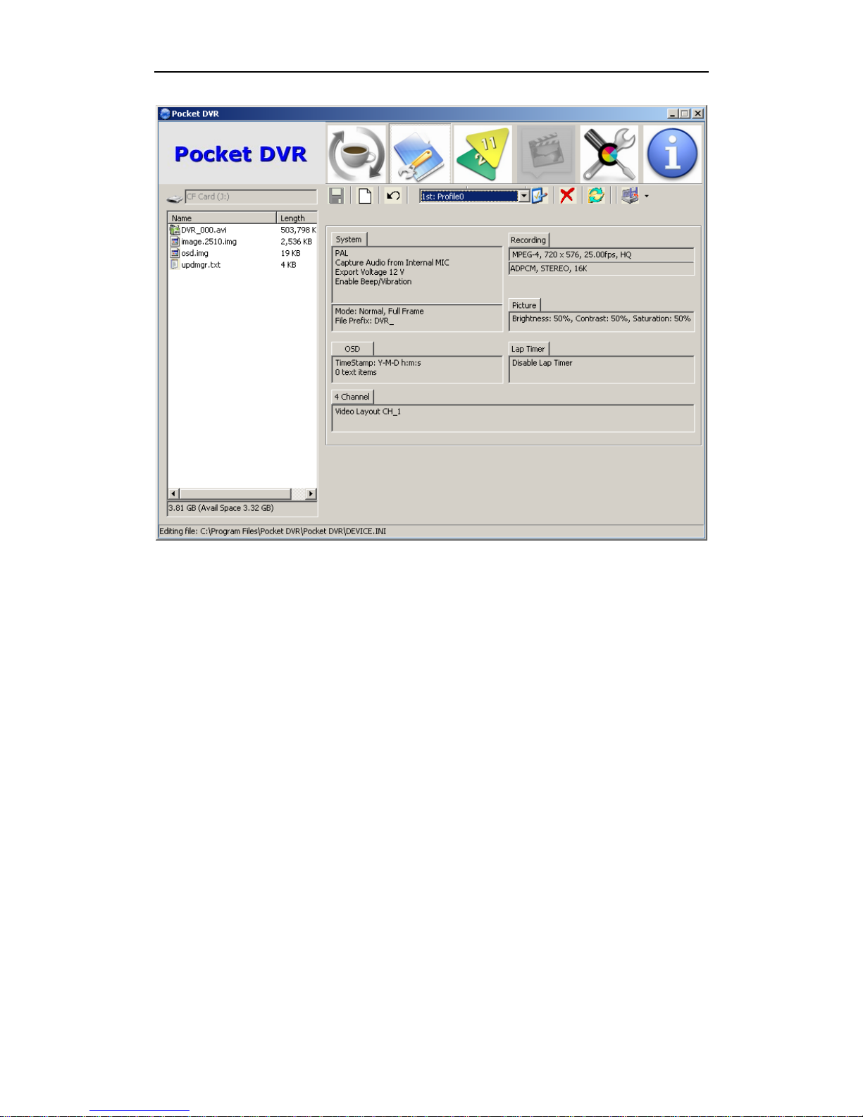
Some functions are active when Desktop software startup via network connection of
DR3 only, because without network connection, you can’t sync/operate DR3 online.
Page 90
Advanced Configuration
- 84 -
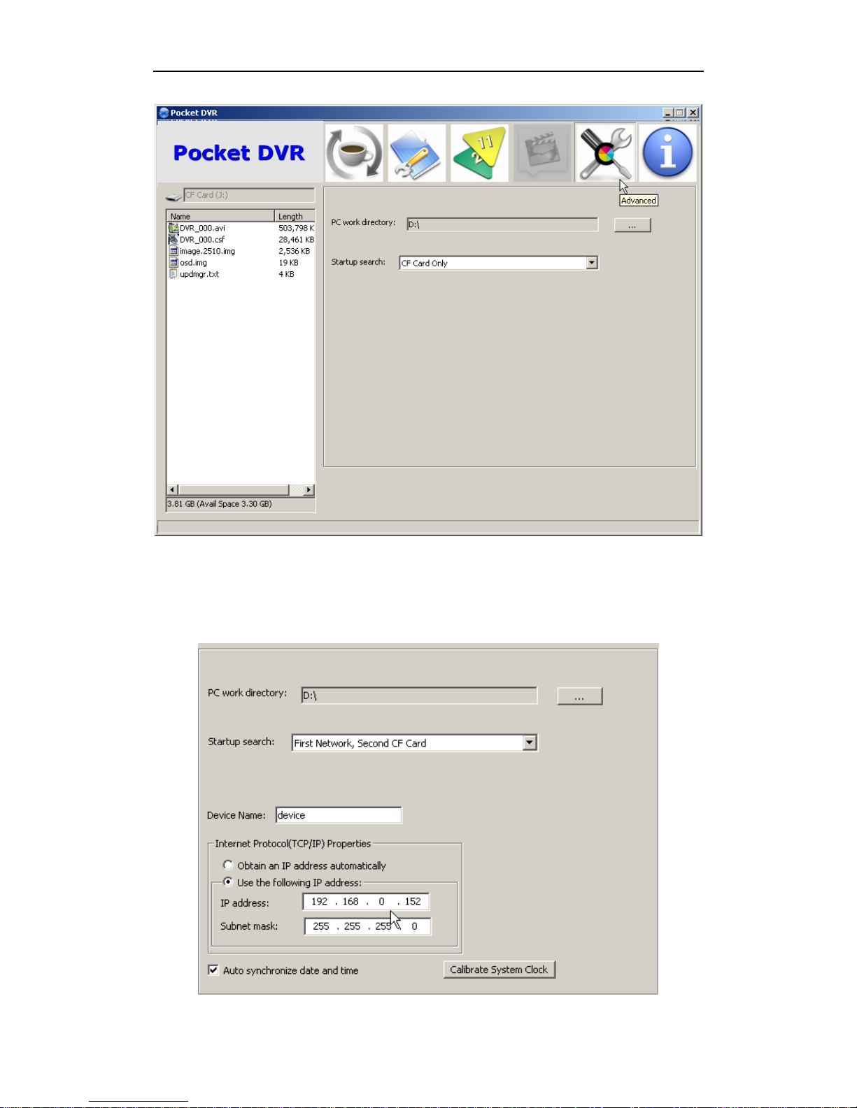
10.3 Configure Network Configuration of DR3
You can change IP address of DR3 manually.
Page 91
DR3 DVR User’s Manual
- 85 -
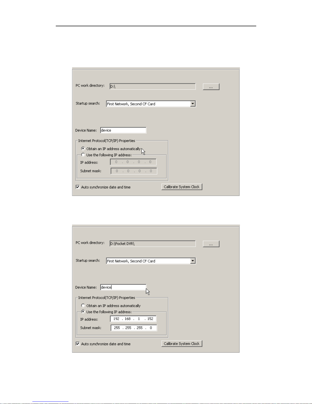
Or you can let DR3 obtain IP address from DHCP server on your local LAN if you
connect DR3 to router or switch. But please notice, the router or switch that be
connected DR3 must support MDI/MDI-X connection.
You can set different Device Name for DR3 if you or your team has some DR3. Then
you can differentiate them based on different device name.
Page 92
Advanced Configuration
- 86 -
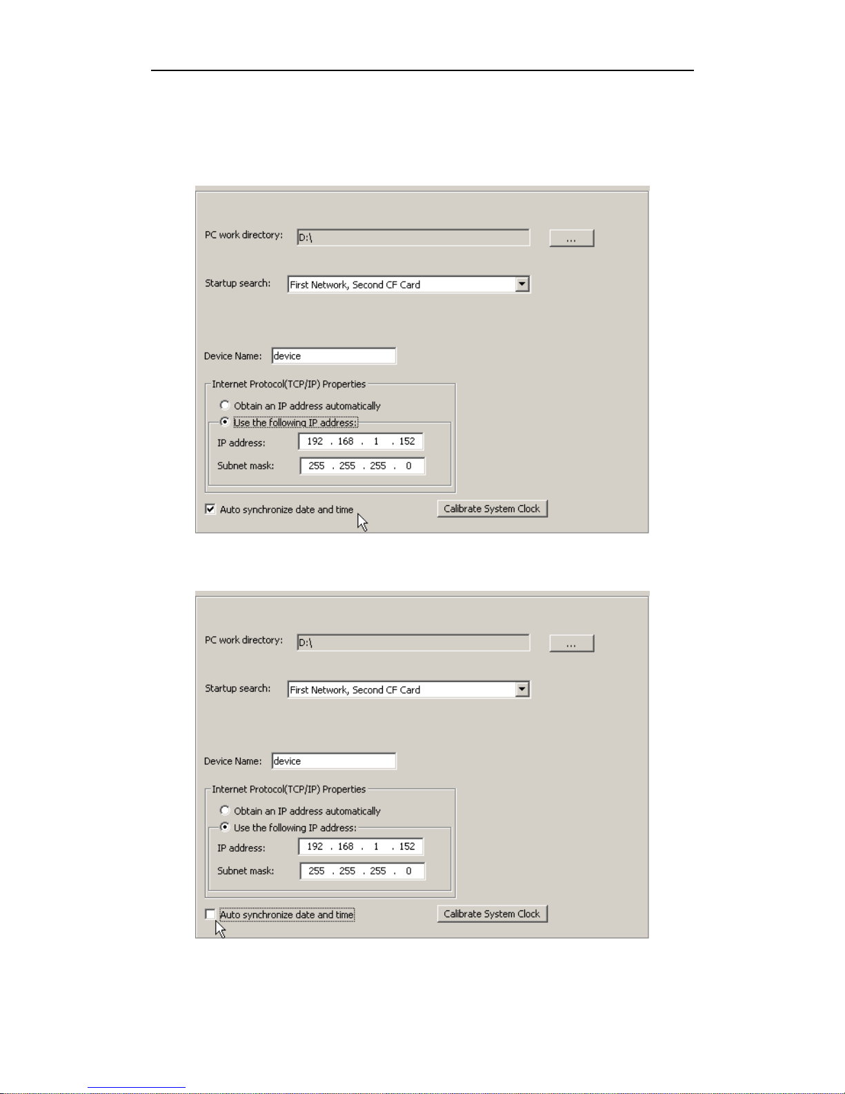
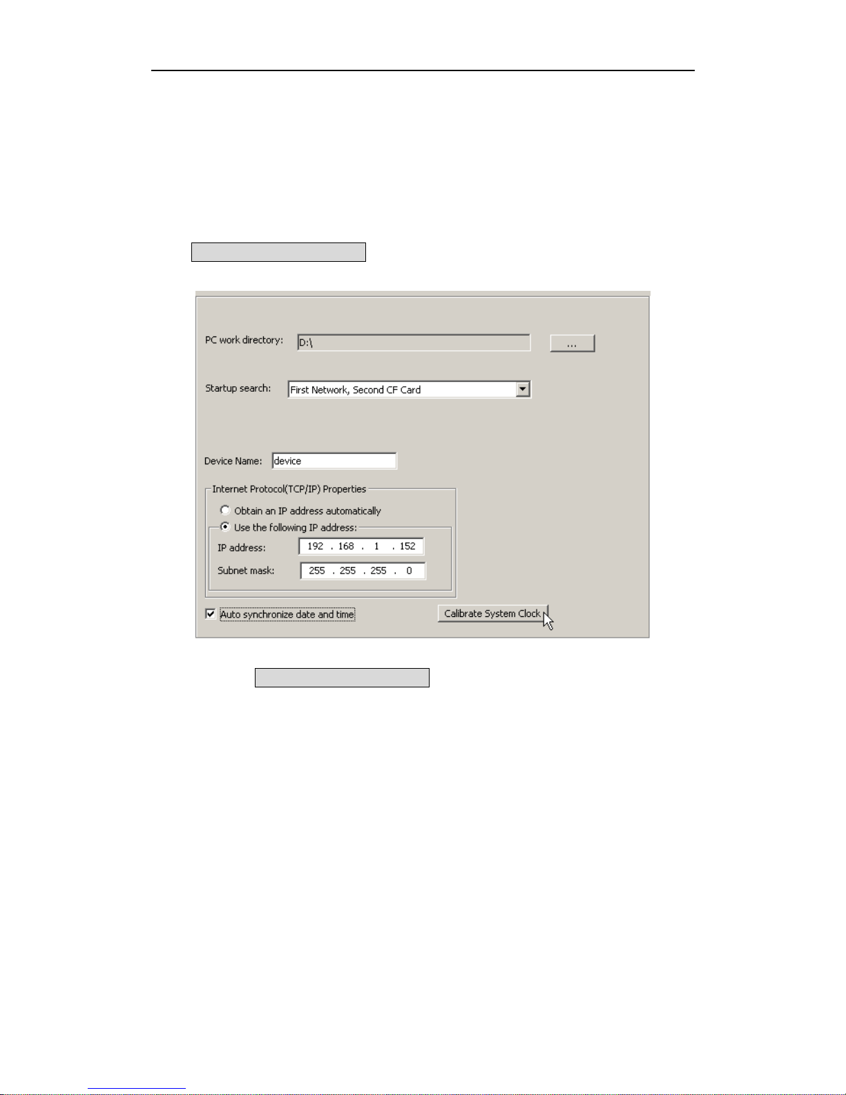
10.4 Auto Synchronize Date & Time between PC & DR3
DR3 Desktop will synchronize Date & Time information based on configuration on
PC automatically.
If you don’t want to synchronize it, you can disable synchronized option.
Page 93
DR3 DVR User’s Manual
- 87 -
After you disable this option, DR3 Desktop will ignore the difference of date & time
between PC and DR3.
10.5 Calibrate System Clock of DR3
Sometimes the system clock of the DR3 need to be calibrated for accurate time
recording, it is important for the Lap Timer. If you need to calibrate the system clock,
click Calibrate System Clock button to calibrate the system clock of DR3
immediately.
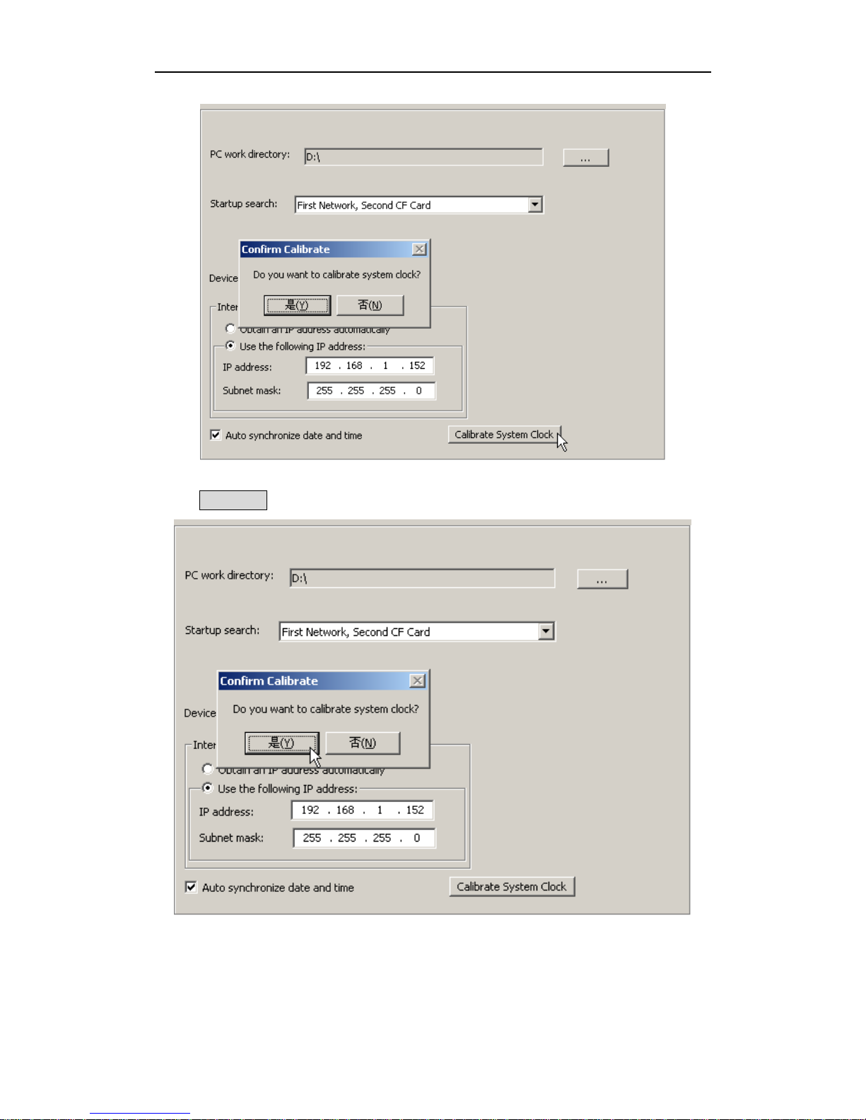
After you click Calibrate System Clock button, Desktop will prompt you to get
the confirm again.
Page 94
Advanced Configuration
- 88 -
Click Yes (Y) button to confirm it again.
After you confirm it, the DR3 will begin to calibrate system clock.
After the system clock of DR3 is calibrated successfully, the DR3 will restart again.
Page 95
DR3 DVR User’s Manual
- 89 -
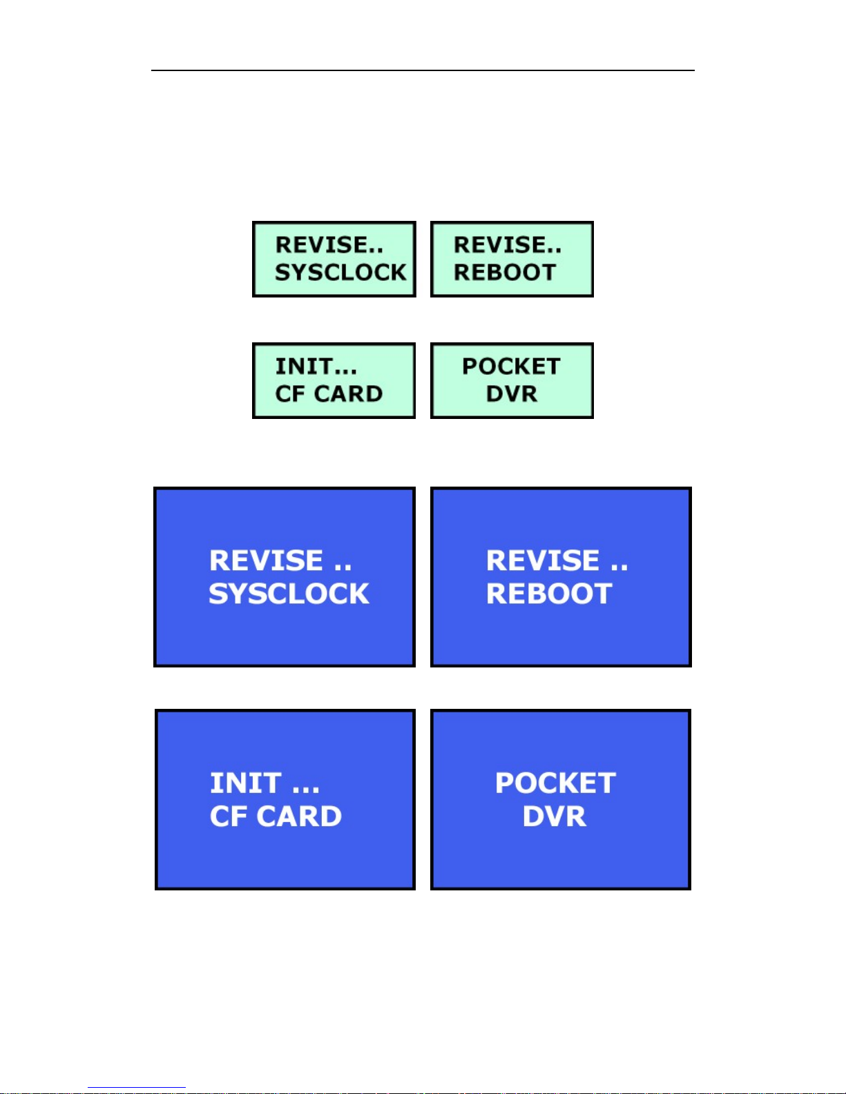
When system clock of DR3 be calibrated & rebooted, LCD on DR3 will display
correlative status information.
10.5.1 Calibrate System Clock of DR3 I
After the system clock of DR3 is calibrated successfully, the DR3 will restart again.
10.5.2 Calibrate System Clock of DR3 II
After the system clock of DR3 is calibrated successfully, the DR3 will restart again.
Page 96
About
- 90 -
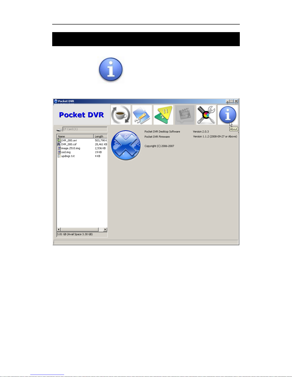
11. About
Click About button to get the details information of DR3 Desktop.
Page 97
DR3 DVR User’s Manual
- 91 -
12. Configure DR3 using LCD
12.1 Configure DR3 I using LCD Menu
IMPORTANT!! If you have a SYSTEM.INI file on a Flash Card inserted in the
DR3, if you change configuration using the LCD Menu and then power the DR3
off and on with the card still inserted, the existing configuration from the
SYSTEM.INI file will be loaded and override the settings you just made.
12.1.1 Enter/Quit LCD Configuration Menu
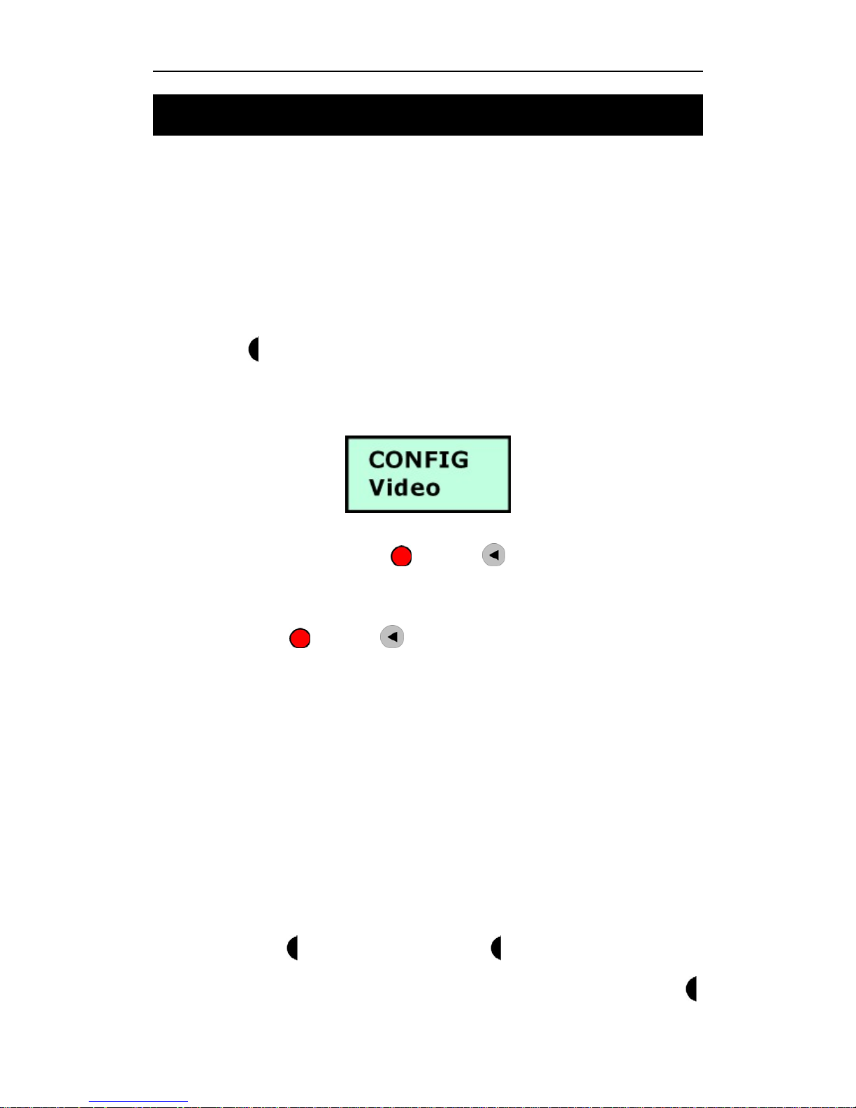
Hold push the 3-Position button at least 3 seconds to enter LCD configuration menu,
once you enter LCD configuration menu successfully, the LCD will display valid
menu/menu item & parameter of these menu item depend on your DR3 I version.
After you finish configuration, press button or Key on IR remote control to
quit to upper menu.
You may need press
button or Key on IR remote control one or two times
once depend on your position in menu.
Once you enter the LCD configuration menu, the system will wait for you to select &
configure, if you don’t press any buttons, the system will quit the LCD configuration
menu after 10 sec automatically.
12.1.2 Configure DR3 I
You can configure DR3 I in LCD menu via push switch/button or IR remote control.
12.1.2.1 Configure DR3 I using switch/button
Once you enter LCD configuration menu, you can switch menu using LEFT &
RIGHT position of
3-Position switch, then press button to select the
menu/menu item which you want to configure, using LEFT & RIGHT position of
Page 98
Configuration DR3 DVR using LCD Menu
- 92 -
3-Position switch to select the parameter value & parameter area that you want to
configure, and then press button to save the configuration.
When you finish configuration, press button one or two times once to quit the LCD
configuration menu.
12.1.2.2 Configure DR3 I using IR remote control
Once you enter LCD configuration menu, you can switch menu using & Key
on IR remote control, then press Key to select the menu/menu item which you
want to configure, using
Key to select the parameter value & parameter area
that you want to configure, and then press
Key to save the configuration.
When you finish configuration, press Key one or two times once until to quit the
LCD configuration menu.
12.1.3 LCD Configuration Menu Details
12.1.3.1 Menu
The valid menu of DR3 is:
● VIDEO
● AUDIO
● RECORD
● OSD
● SYSTEM
● 4CH
● BEACON
In LCD configuration menu, switch LEFT & RIGHT position of 3-Position switch
or using Key on IR remote control to navigate these menus.
Press button or Key to quit configuration menu return to ready status.
Page 99
DR3 DVR User’s Manual
- 93 -
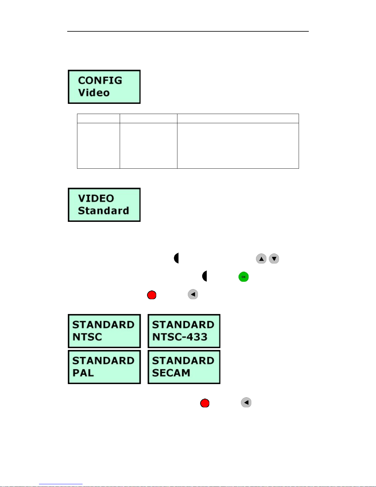
12.1.3.2 VIDEO Menu
Menu Menu Item Parameter
VIDEO
VIDEO
Standard
STANDARD
● NTSC
● NTSC-433
● PAL
● SECAM
● Menu Item – VIDEO / Standard
Default parameter is PAL, please select correct video standard depend on your video
source.
Switch LEFT & RIGHT position of 3-Position switch or press Key to
switch the video standard parameter, then press button or Key to save the
current configuration, press
button or Key to quit the VIDEO /
STANDARD menu.
After you finish all video configuration, press
button or Key to quit the
VIDEO menu.
12.1.3.3 AUDIO Menu
Page 100
Configuration DR3 DVR using LCD Menu
- 94 -
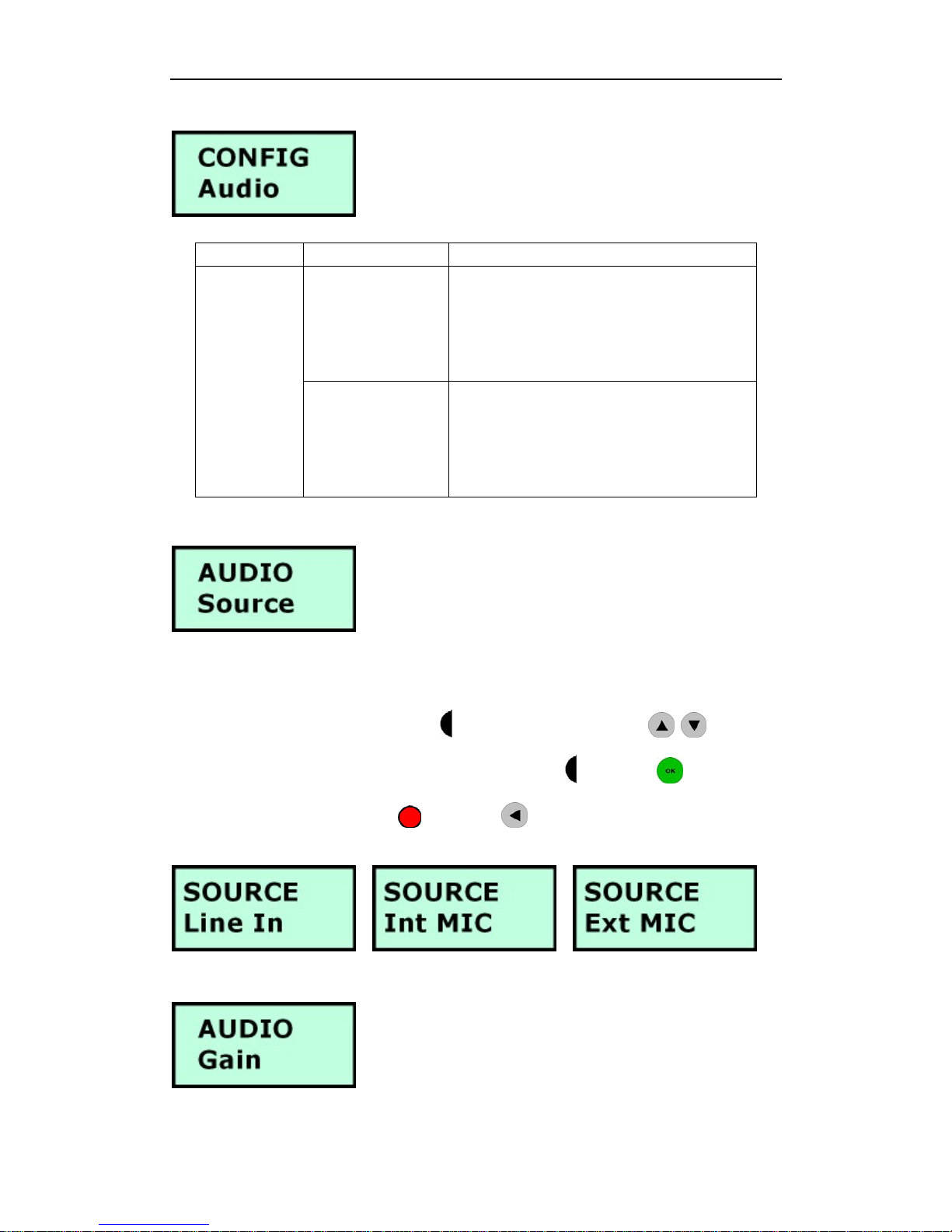
Menu Menu Item Parameter
AUDIO
Source
SOURCE
● Line In
● Ext MIC
● Int MIC
AUDIO
AUDIO
Gain
GAIN
● Low
● Medium
● High
● Menu Item – AUDIO / Source
Default parameter is Line In, please select Ext MIC if you use external microphone
input, or select Int MIC if you use internal microphone in the DR3.
Switch LEFT & RIGHT position of 3-Position switch or press Key to
switch Line In, Ext MIC & Int MIC input, then press button or Key to save
the current configuration, press button or Key to quit the AUDIO / Source
menu.
● Menu Item – AUDIO / Gain
 Loading...