

Drivecon XT Series Service Manual
Service Manual
Pro2V070
XT SERIES
Service Manual
820 Lakeside Drive – Gurnee, IL 60031
Phone: 1-800- 374-8266
Fax: (847) 855-9650
www.drivecon.com
XT Series rev 5.5B Pro2V070

?
Page 1
Service Manual
Pro2V070
CAUTION
1. Before starting, read the instructions carefully.
2. Verify all of the connections are in accordance to the drawings.
3. Verify the motor supply is connected correctly; faulty connection will
destroy the inverter.
4. Check the device cover is properly installed.
5. High voltages are present in this device. Switch the power off and after
the display turns off, wait 5 minutes before opening the cover.
6. Insulation resistance test with a megger requires special precautions.
7. Do not make any measurements inside the device when it is connected
to the main supply.
8. Do not touch the components on the circuit boards. Static voltage
discharge may cause damage or destroy the IC-circuits.
9. Check all ventilation holes are clear and uncovered.
10. Check that hot air coming from the brake resistors does not cause any
danger.
11. Do not make any inspections unless the supply has been disconnected
by the main switch.
12. It is forbidden to use radiophones or portable phones near this device
with the doors open.
13. All the doors and covers must be closed during crane operation.
?
This manual is valid for XT Series revisions 5.5. The release number of this document is XT
SERIESCSM55BEN. The parameter numbers are based on the software version Pro2V070.
?
Drivecon Inc. reserves the right to alter or amend the above information without notice 21.12.2004 • XT SERIESCSM55BEN

CONTENTS
1 GENERAL................................ ................................ .......................................................4
1.1 Technical data ................................ ................................ .......................................4
1.2 Type mark coding................................ ................................ ..................................5
1.3 Basic description ................................................................ ................................ ...6
1.4 Main components ................................................................ ................................ ..7
1.5 Functional description................................................................ ............................ 8
1.6 Control methods ................................ ................................ ................................ .... 9
1.7 Mechanical brake control ................................ ................................ .....................12
1.8 Motor control modes ................................ ................................ ............................13
1.9 EMC ................................................................ ................................ ...................14
1.9.1 Fulfilled EMC-standards ................................ ................................ ............14
2 INSTALLATION ................................ ................................ .............................................16
2.1 Cooling................................ ................................................................ ...............16
2.2 Power cabling ................................ ................................ ......................................16
2.3 Control wiring................................................................ ................................ ......19
2.4 EMC compatible grounding ................................ ................................ ...................19
3 START -UP PROCEDURE................................................................ ...............................20
3.1 Visual checks ................................ ................................ ......................................20
3.2 Checks before the first test run................................ ................................ .............20
3.3 Test run without load ................................................................ ...........................21
3.4 Test run with load................................ ................................ ................................21
3.5 After the test run ................................................................ ................................ .21
4 PARAMETER ADJUSTMENTS ................................ ................................ ........................22
4.1 Control keypad operation ................................................................ .....................22
4.1.1 Navigation on the control keypad ...............................................................23
4.1.2 Value line editing................................ ................................ ......................23
4.1.3 Passwords................................................................ ................................24
4.1.4 Special button functions ................................................................ ............24
4.1.5 Monitoring................................ ................................ ................................25
4.2 Input selections ................................................................................................ ...26
4.3 Speed supervision settings................................................................ ...................27
4.3.1 Functional test run for SSU................................ ................................ ........29
4.4 Open Loop motor parameter adjustments ..............................................................30
4.4.1 Open Loop speed control for hoisting ................................ .........................30
4.4.2 Open Loop rated motor parameters for traveling .........................................30
4.4.3 Open Loop autotuning for traveling, frequency control.................................32
4.4.4 Open Loop manual tuning for travelling ......................................................32
4.4.5 Open Loop manual tuning for traveling, frequency control ............................34
4.4.6 Open Loop manual tuning for traveling, current control ................................34
4.5 Closed Loop motor parameter adjustments................................ ............................36
4.5.1 Closed Loop rated motor parameters..........................................................36
4.5.2 Closed Loop autotuning, speed control ................................ .......................37
4.5.3 Closed Loop manual tuning for hoisting, speed control ................................ 41
5 PARAMETER DESCRIPTIONS ................................ ................................ .......................44
Page 2
Service Manual
Pro2V070
6 COMPONENTS ................................................................ ................................ .............58
6.1 Inverter ................................................................................................ ...............58
6.1.1 Power supply unit (PSU) ................................ ................................ ............60
6.1.2 Control unit (CSU) ................................................................ ....................60
Drivecon Inc. reserves the right to alter or amend the above information without notice 21.12.2004 • XT SERIESCSM55BEN

6.1.3 Basic I/O board (Slot A) ................................................................ ............61
6.1.4 Relay / Thermistor board (Slot B)...............................................................62
6.1.5 SSU Speed Supervision board (Slot C) .......................................................62
6.1.6 I/O Extension board (Slot D)................................................................ ......63
6.1.7 Relay Extension board (Slot E) ................................ ................................ ..63
6.1.8 Profibus board (Slot E)................................................................ ..............65
6.2 Reference potentiometer......................................................................................67
6.3 Speed sensors ................................ ................................ .....................................69
6.3.1 Encoder (if applicable) ................................................................ ..............69
6.3.2 Sensor bearing (if applicable) ....................................................................71
6.3.3 Proximity switch (if applicable) ................................................................ ..72
6.3.4 Buffer amplifier KAE234 (if applicable) .......................................................73
6.4 Brake controllers ................................ ................................ ................................ .75
6.4.1 REC12-690+DC ................................ ................................ ........................75
6.4.2 ESD141................................ ................................ ................................ ....75
7 TROUBLESHOOTING................................................................ ................................ ....76
7.1 Field repair actions................................................................ ..............................76
7.2 Inverter fault codes ................................ ................................ ..............................77
7.2.1 Fault time data record ................................................................ ...............83
7.2.2 Fault Counter ................................ ................................ ...........................84
7.3 Inverter Alarm codes................................ ................................ ............................85
8 SERVICE ................................ ................................ ......................................................86
8.1 DC-bus electrolytic capacitors ................................................................ ..............86
8.1.1 Re-forming after a long storage period .......................................................86
9 GENERAL DRAWINGS ................................ ................................ ................................ ..87
Page 3
Service Manual
Pro2V070
Drivecon Inc. reserves the right to alter or amend the above information without notice 21.12.2004 • XT SERIESCSM55BEN

Page 4
Service Manual
Pro2V070
1 GENERAL
1.1 Technical data
Power class 4004 4005 4009 4012 4016 4022 4031 4038 4045 4061 4072 4087 4105 4140F 4168 4210
Horsepower (Hp) at 460V 2 3 5 7.5 10 15 20 25 30 40 50 60 75 100 125 150
Output current In (A) 4.3 5.6 9 12 16 23 31 38 46 61 72 87 105 140 170 205
Max. current 1min (A) 6.5 8.4 13.5 18 24 35 47 57 69 92 108 131 158 210 255 308
Max. current ,Is,2 sec (A) 8.6 10.8 18 24 32 46 62 76 92 122 144 174 210 280 336 410
Overloadability 1.5 x In, 1min/10min
Max. output voltage Equal to supply voltage
Supply
Supply voltage 380-500VAC
Allowable voltage fluctuation +/- 10%
Nominal supply frequency 50/60Hz +/- 5%
Signal input levels
Digital controls S1, S2, DIA3, DIA4, DIA5, DID1, DID2, DID3, DID4, DID5: 42 … 240VAC; 15mA
Analog references
Encoder feedback EA+/- and EB+/-; 0/24V; 3k? load; floating differential inputs
Control features
Control method Open loop or closed loop vector control
Frequency control range 0 ... 250Hz
Frequency command Potentiometer, motor potentiometer, 2 -4-step controller or 0 ... 10V analog signal
Limit switch functions Slowdown and stop limit inputs for both directions
Speed control range Open loop vector control
sN ... 100% (sN= motor nominal slip)
Closed loop vector control
0 ... 100%
Speed accuracy Open loop vector control
Closed loop vector control
0.01% of nominal speed
Extended speed range 100 ... 200%
Braking torque 150%
Protections
Stall prevention During acceleration and constant speed
Motor overload protection Thermistor based temperature measurement
Overload protection Fault is detected if the current momentarily exceeds 280% of rated current
Undervoltage / blown fuse Fault is detected if DC voltage drops below 333V
Overvoltage protection Fault is detected if DC voltage exceeds 911V
Momentary power loss Immediate fault stop
Inverter overtemperature Temperature sensor on the heat sink
Mechanical brake Circuit breaker
Braking transistor Electronic supervision for the braking chopper and for the braking resistor
Brake slip protection Programmable relay output
Ground fault Provided by electronic circuitry
Overspeed / stall,
Speed difference supervision Independent measurement using pulse wheel or encoder
Ambient conditions
Ambient temperature
Storage temperature
Humidity <95%RH (no condensation)
Altitude Maximum 1000m at In. Above 1000m: In reduces 1% per each 100m.
Above 3000m: consult factory.
Vibration Operation: maximum displacement amplitude 3mm at 2-9Hz.
Maximum acceleration amplitude 0.5g (5m/s²) at 9-200Hz
Conforms to LV and EMC directives.
1% of nominal speed at speed range 10 ... 100%
1/3 of motor nominal slip at speed below 10%
Drivecon Inc. reserves the right to alter or amend the above information without notice 21.12.2004 • XT SERIESCSM55BEN
AIN1: 0 … +10V and AIN2: -10 … +10V; 200k? load? accuracy 0.5%
-10?C ... +55?C (14?F ... 131?F) for ED?60%
-40?C ... +60?C (-31?F ... 140?F) dry. Power on >1h in a year.
Page 5
Service Manual
Pro2V070
Type mark coding
XT SERIES can be summarized as "crane motor control systems, which controls the speed by
changing the frequency of supply voltage of a squirrel cage motor". A stepless speed adjustment
can be achieved by this method.
Type marking is shown below.
000 XTx
Device name
000- Base Drive (430,440)
000-Pre-engineered Panel (488,489,490,491,492,493,494,496,497,498,499)
x- d (Base drive vector), e (base drive vector with SSU board), s (open loop
vector panel), v (closed loop vector panel)
XT Series
Supply voltage
4
4 380 - 500VAC, 50/60Hz
6 525 - 690VAC, 50/60Hz
009
Rated Amps
009=9A, 168=168A
TC
Panel Motion and Duty Class
XX=Base Drive only
TC=Traverse class C
TD=Traverse class D
HC=Hoist class C
HD=Hoist class D…etc
0 Option Control PCB’s
0 Standard (A,B,D)
1 Standard with SSU (A,B,C,D)
2 Profibus (A,B,D,E)
3 Profibus with SSU (A,B,C,D,E)
8 Relay (A,B,D,E)
9 Relay with SSU (A,B,C,D,E)
000 XTx 4 009 TC 0 55 0
Software Revision code
The latest revision may differ
Special
0 None
L Varnished boards
Drivecon Inc. reserves the right to alter or amend the above information without notice 21.12.2004 • XT SERIESCSM55BEN
0
55

Page 6
Service Manual
Pro2V070
1.2 Basic description
XT SERIES have many advantages and offer many new features, when compared to other
inverter-based systems, which might be used in crane applications.
Inverter
Crane user interface
Brake control
Electrical braking
Control methods
Limit switch
functions
Speed supervisio n
Protections
The inverter in XT SERIES is a crane inverter. The specific crane
features for the inverter hardware and the special software are
achieved by combining the experience and know-how of crane
applications with the latest technology. The inverter uses vector
calculation for several different motor control modes.
All XT SERIES have exactly the same interface with pre-designed
locations for all typical crane functions. The main part of this interface
is carried out by a terminal strip, which has separated sections for
signals with main, control and electronics voltage levels.
XT SERIES include the brake contactor for disk brakes. XT SERIES
also includes it’s own DC-rectifier.
XT SERIES include a braking transistor, which is dimensioned for every
crane application. For resistor braking XT SERIES are equipped with
external resistor.
XT SERIES can be controlled by the electronic potentiometer control
with 2-step pushbuttons, the potentiometer control with analog joysticktype control, the automation control with PLC and radio controls and by
the multistep control with 2-4-step controllers. All these control methods
are available with every XT SERIES.
XT SERIES have built-in slowdown and stop limit switch functions for
both running directions.
XT SERIES include a speed supervision unit SSU, which is separate
from the inverter and not dependent on software. This safety circuitry is
used to monitor the speed of the motor. In case of speed difference,
overspeed or stall, the speed supervision unit stops the motion
immediately. It can also be equipped with SSU.
XT SERIES include a motor thermal protection, which is based on
motor temperature measurement by thermistors placed in the motor
windings. A great number of other protections included in every XT
SERIES are shown in the technical data.
Drivecon Inc. reserves the right to alter or amend the above information without notice 21.12.2004 • XT SERIESCSM55BEN

1.3 Main components
The main components are:
Page 7
Service Manual
Pro2V070
A1 Inverter 002-132F
F7 Input supply circuit breaker 007-132F
K7 Brake contactor 002-132F
F71 Circuit breaker for the brake contactor 055-132F
XT SERIES
The most important external components are:
R1 External braking resistor unit
M1 Motor
Y1 Mechanical brake
B5 Speed sensor (P-models)
B6 Encoder (N-models)
Thermal sensor for motor protection
Overload protection device (e.g. Premium)
Control devices (switches, pushbuttons, potentiometers etc.)
Limit switches
Drivecon Inc. reserves the right to alter or amend the above information without notice 21.12.2004 • XT SERIESCSM55BEN

1.4 Functional description
See circuit diagrams for following descriptions of operation.
Operation when
power is switched on
Normal operation
Other features
Limit switches S11, S12, S21 and S22 are assumed to be closed, as
??
well as the emergency stop button ES.
The control voltage is supplied to A1 control inputs (external
??
42V…230V control voltage). The main voltage is connected to
inverter power supply and inverter turns on. If the control voltage is
connected to RDY -signal and the fault circuit is OK, inverter is ready
to operate in about 1-2 seconds.
?? If either one of the direction signals S1 or S2 is on, the display
shows F6 and running can begin only after the direction signals have
been off for a while.
–
For the description of the speed reference setting see chapter 1.6
"Control methods".
–
Running starts when switch S1 (S2) closes. Closing the contact
ROB2 on A1 energizes K7, which opens the brake. XT SERIES
accelerate according to the acceleration ramp setting to the selected
speed.
–
When the switch S1 (S2) opens, XT SERIES stop according to the
deceleration ramp setting and then the brake closes.
–
R1 dissipate the regenerated energy during deceleration and
lowering periods. The power supply to R1 is controlled by A1. If the
braking resistor fan(s) are included in external resistor unit, they
start to operate when power is supplied to the braking resistors. The
cooling continues about 4-5 minutes after electrical braking to
ensure that the temperature of the resistors drops below 150? C
(302?F).
–
Slowdown limit switches S11 and S21 provide position dependent
frequency limiting.
–
Any reason, which opens the contact RDY, stops the operation of
inverter A1.
–
In case of overload, motor overheating etc. the hoisting can be
disabled by cutting the direction signal.
–
Thermistor relay function, which can be used when needed.
–
When the stop limit switch S12 or S22 opens, K7 de-energizes and
the mechanical brake stops the motion.
–
Independent speed supervision unit, SSU.
–
The speed measurement and supervision can be done either with
encoder, bearing encoder or proximity switch. The measured signals
are square wave pulses. The frequency of the pulses is proportional
to the speed of the motor and if the frequency is too high, ove rspeed
is detected. If there are no pulses a stall situation is detected. If the
actual speed differs too much from the supply frequency of the
motor, the speed difference supervision stops the motion.
–
Proximity switch buffer amplifier amplifies the sensor pulses and
filters out disturbances. The amplifier is located close to the sensor.
–
The extended speed range ESR can be used, if the signal FWE (field
weakening enabled) is on. Then it is possible to run up to twice the
nominal speed depending on the a pplication.
Page 8
Service Manual
Pro2V070
Drivecon Inc. reserves the right to alter or amend the above information without notice 21.12.2004 • XT SERIESCSM55BEN
Page 9
Service Manual
Pro2V070
1.5 Control methods
There are four different control methods (command modes) available. All of them are available
without any changes in the hardware or software. Any single XT SERIES can be controlled either
by a pushbutton controller in EP -mode, by a joystick type controller with a potentiometer located in
the cabin in PO -mode or by a process computer in AU -mode. The only external device needed is a
switch to select the desired control method.
Command mode
selection
PO- and AU -modes
DIA3
DIA4
EP-mode
DIA3
DIA4
EP Electronic motor potentiometer function.
?? Stepless control using a 2-step pushbutton controller.
?? EP3 stepless control using a 3-step controller.
PO Potentiometer control using a joystick type controller.
?? Requires a single 15V power supply (included in XT SERIES).
?? Any ad ditional amplifier is not needed.
AU Automation control
For any control device with an output in the range of 0-10V.
??
?? E.g. radio-controls, process computers.
MS Multistep control (2-4 steps as standard).
Requires programmable digital inputs for speed reference steps
??
(included in XT SERIES).
The command mode (EP, PO or AU) is selected by the switches CMS
and AP. Normally the selection can be done only when the motion is
stopped (not when running), but in special applications changing the
mode is allowed during run by changing parameter values.
PO - and AU-modes select either of the analog inputs for speed
reference. Both analog inputs can be adjusted similar from 0V to 10V
(radio or PLC-reference) or from 10V to 6.7V (potentiometer). As
default, Ain1 is used in PO-mode and Ain2 is used in AU -mode.
Ain1 / PO Ain1 / PO Ain2 / AU Ain2 / AU Ain1 / PO
AP not used AP not used
CMS not
used
EP-mode selects the AP-button for speed reference. EP step 1 is
command for minimum speed or hold speed. EP step 2 is the
acceleration command.
EP step 1 EP step 2 EP step 1 EP step 2
AP = 0 AP = 1 AP = 0 AP = 1
CMS not
used
CMS = 0 CMS = 1 CMS = 1 CMS = 1
CMS not
used
AP not used AP = 0 AP = 1
CMS = 0 CMS = 0
Drivecon Inc. reserves the right to alter or amend the above information without notice 21.12.2004 • XT SERIESCSM55BEN

Synchronization
If required, two or more XT SERIES can be run in precise
synchronization. A separate synchronization controller is needed for
this. The same speed reference (in EP- or PO-mode) is connected to
every XT SERIES and the correction signal for synchronization is
connected to all XT SERIES to input AIN2+. The speed reference signal
of each XT SERIES can also be modified separately by a PLC.
Synchronization is activated by parameter selection.
Page 10
Service Manual
Pro2V070
Drivecon Inc. reserves the right to alter or amend the above information without notice 21.12.2004 • XT SERIESCSM55BEN
Description of the control methods
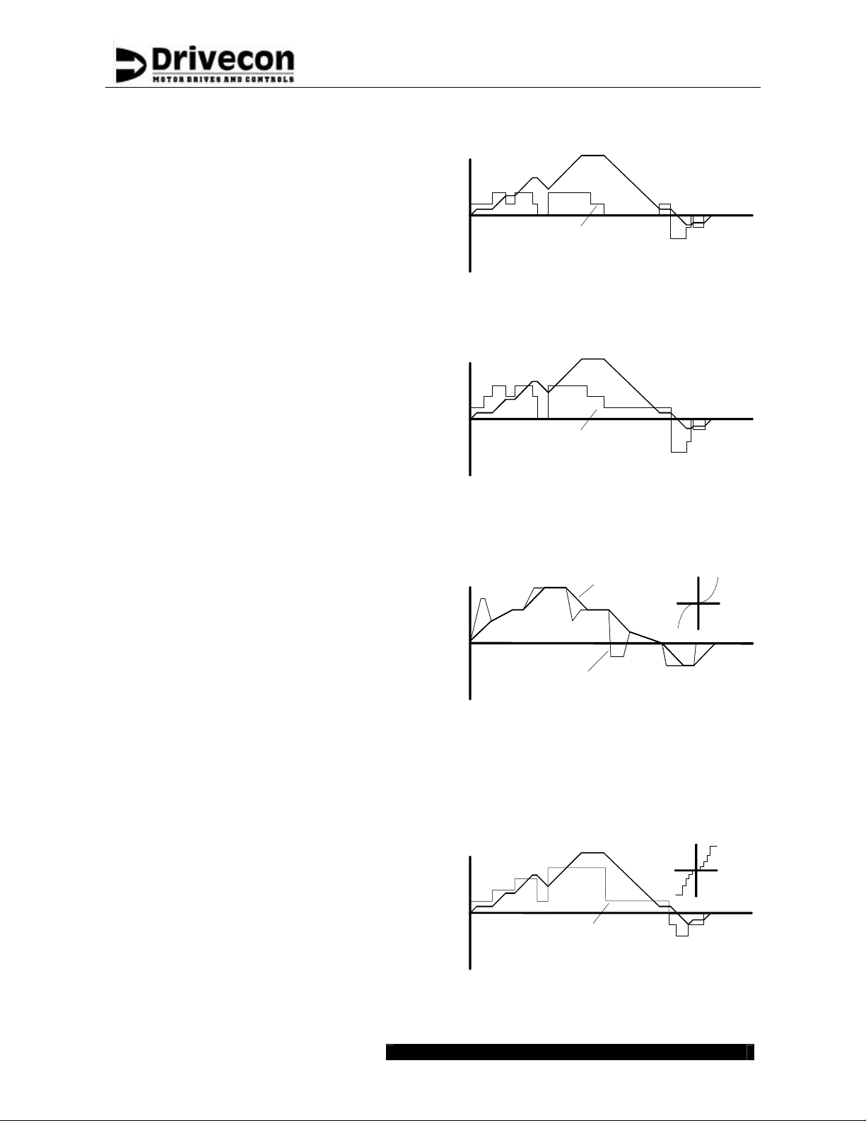
EP-control requires two 2-step pushbuttons, one
for each direction. The operation is as follows:
?? the rest position means standstill (0-position)
?? during run the rest position means deceleration
step one (switch S1 or S2) means hold speed
??
when starting, step one means acceleration up to
??
the minimum speed
step two (switch AP) means acceleration (up to
??
the maximum speed if desired)
?? at the maximum speed step two means hold
speed, because the maximum speed cannot be
exceeded
EP3-control requires a 3-step controller. The
operation is as follows:
?? the rest position means standstill (0-position)
?? step one (switch S1 or S2) is the minimum speed
command
?? step two (EP hold command) means hold speed
?? step three (switch AP) means acceleration (up to
the maximum speed if desired)
?? when releasing the controller, step one means
deceleration down to the minimum speed
PO-control requires a controller with
potentiometer. The operation is as follows:
when the controller is at the rest position, the
??
potentiometer is at the middle position causing
zero speed
run commands are controlled separately by
??
closing the direction switches (S1 and S2)
?? when the operator turns the controller to any
direction, the speed increases
?? the same turning angle of the controller causes a
smaller change in speed, the closer the speed is
to the minimum speed
AU -control requires an analog reference from radio
or PLC. The operation is as follows:
?? the speed linearly follows the input signal. 0V
means zero speed and the higher the voltage,
the higher the speed
?? run commands are controlled separately by
closing the direction switches (S1 and S2)
MS-control requires a 2-4-step controller. The
operation is as follows:
each step has its own frequency
??
the frequencies are freely selectable
??
?? when controller is set to a certain step, the speed
changes to equal value
Page 11
up / fwd
down / rev
up / fwd
down / rev
up / fwd
down / rev
up / fwd
Service Manual
Pro2V070
Pushbutton position
speed
pushbutton
position
EP-mode
speed
pushbutton
position
EP3-mode
speed
potentiometer reference (controller position)
or auxiliary reference
PO - and AU -modes
controller
position
rest = deceleration
step 1 = hold speed
step 2 = acceleration
Pushbutton position
rest = stop
step 1 = minimum speed
step 2 = hold speed
step 3 = acceleration
speed
controller
position
speed
speed
controller
position
time
time
time
time
down / rev
MS -mode
Drivecon Inc. reserves the right to alter or amend the above information without notice 21.12.2004 • XT SERIESCSM55BEN

Page 12
Service Manual
Pro2V070
1.6 Mechanical brake control
The brake is controlled so that during starting, the motor first generates torque and after that the
brake is opened. The same applies for stopping; while the brake is being closed, the motor still
generates torque. During a direction change, the brake is kept open all the time. XT SERIES
decelerate the motor to a stop according to the set deceleration time when the run command is
switched off, so the brake is used only as a holding brake. This way brake wear is minimized. Only
if a failure occurs or the emergency stop button is pushed, the brake closes immediately stopping
the motor and the load.
The motors of CXT -hoists an d SM-trolleys have an electromechanical disk brake. The disk brake is
opened and kept open during run by DC-voltage. When there is no voltage present the brake is
closed and also kept closed by spring force.
2-phase AC
3-phase AC
XT SERIES models may include an AC-supply from two phases for the
brake control. XT SERIES controls this line and it is protected by an
adjustable circuit breaker. An external rectifier may be included to
rectify the AC -voltage to DC-voltage for DC brake coils.
XT SERIES models may include a 3-phase AC-supply for the brake
control. XT SERIES control this line and it is protected by an adjustable
circuit breaker.
Drivecon Inc. reserves the right to alter or amend the above information without notice 21.12.2004 • XT SERIESCSM55BEN
Page 13
Service Manual
Pro2V070
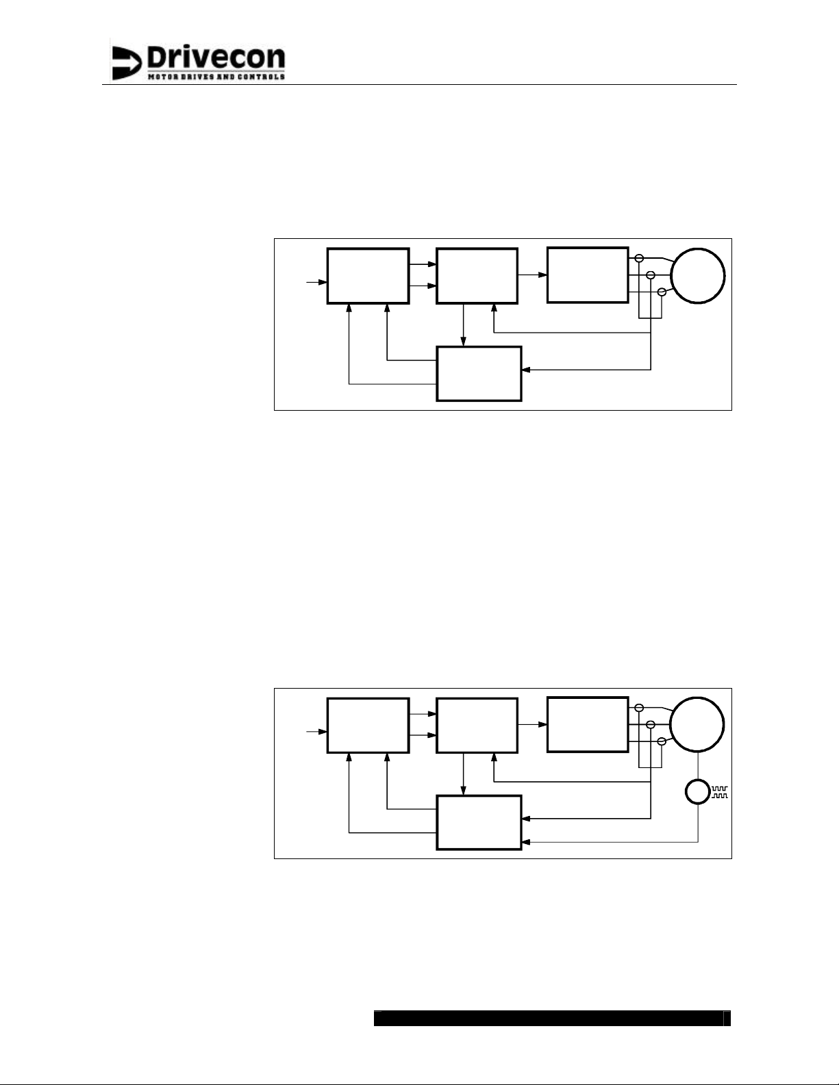
1.7 Motor control modes
Open loop
XT SERIES have a built-in motor model, which calculates - one thousand times in a second - the
values of the real motor. The input data needed for the calculation is the instantaneous value of
the motor voltage from the ASIC and the measured motor current. Motor magnetic flux and shaft
torque are calculated in the motor model based on the nameplate data of the motor.
Open loop
Vector control
Speed
ref
Speed
Control
ref
InverterAsic
M
~
3
Torque
Vector
calculation
Frequency control
Open loop (mode 0)
Current control
Open Loop (mode 1)
Flux
In frequency control mode of Open Loop, the motor frequency follows the
frequency reference signal. The actual rotating speed depends on load and is
equal to the slip below or above the output frequency. Even with frequency
control, the vector calculation is used to keep the magnetization at a correct
level.
In current control mode of Open Loop, the motor follows the frequency
reference signal. The motor is current controlled in small frequencies
(typically <10Hz) and in higher frequencies the motor is voltage controlled.
The current control ensures that in small frequencies the speed of the motor is
almost independent of the load.
Closed loop
The closed loop vector control also includes a motor model, which has even a simpler
configuration than the open loop vector control. This is because an additional input data, as the
signal from the incremental encoder is available. This measurement of the function of the actual
motor is used as feedback to the motor model calculation and allows possibilities for additional
checking of the motor control.
Closed loop vector
control
Speed
ref
Speed
Control
ref
Current
InverterAsic
M
~
3
Torque
Flux
Speed control
Closed loop (mode 3)
Torque control
Closed loop (mode 4)
Drivecon Inc. reserves the right to alter or amend the above information without notice 21.12.2004 • XT SERIESCSM55BEN
In the speed control mode of Closed Loop, the motor speed follows the speed
reference signal. XT SERIES adjust the motor frequency and with this function
compensates the load-dependent slip. The slip compensation keeps the actual
shaft speed constant and independent of loading conditions. With the closed
loop speed control it is even possible to reach zero speed with full torque.
In torque control mode, the shaft torque is kept equal to the reference signal.
The motor speed depends very much on loading conditions - for example, an
unloaded motor would run at full speed all the time. For safety reasons, the
speed is limited between adjustable minimum and maximum speeds.
Vector
calculation
Current
Speed
G
Page 14
Service Manual
Pro2V070
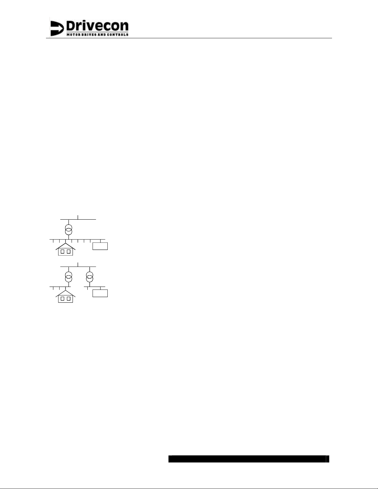
1.8 EMC
The shortening "EMC" stands for the Electro Magnetic Compatibility. According to the EMC
directive "the apparatus shall be so constructed that:
a) The electromagnetic disturbance it generates does not exceed a level allowing other
apparatus to operate as intended
b) The apparatus has an adequate level of intrinsic im munity of electromagnetic disturbance to
enable it to operate as intended."
Technical
construction file
Declaration of
conformity
CE -mark
Environments
PDS
PDS
The technical construction file describes how the frequency converters
have been constructed to comply with the directive and standard
requirements.
With the declaration of conformity the manufacturer informs that device
is manufactured to fulfill required EMC standards.
The CE marking is a declaration by a manufacturer or importer located
in the European Economic Area that a product complies with the safety
and health requirements of the directive in question. The manufacturer
demonstrates for the authorities that the product complies with the
safety requirements within the EU.
Immunity and emission requirements are divided in two levels in the
product standard according to the environments.
First environment means environment that includes domestic premises
and also establishments directly connected to a low-voltage power
supply network.
XT SERIES are not intended to be used on a low-voltage public
network, which supplies domestic premises. Radio frequency
interference is expected if used on such a network.
Second environment means environment that includes all
establishments other than those directly connected a low-voltage power
supply network.
Power drive system (PDS) means a system consisting of power and
control equipment, including XT SERIES.
1.8.1 Fulfilled EMC-standards
Immunity
Emissions
Drivecon Inc. reserves the right to alter or amend the above information without notice 21.12.2004 • XT SERIESCSM55BEN
XT SERIES fulfill the immunity requirements defined in the EN 61800 -3
Amendment 11 (2000) for the second environment.
XT SERIES fulfill the emission requirements of the EN 61800-3 A11
2000 for the second environment.
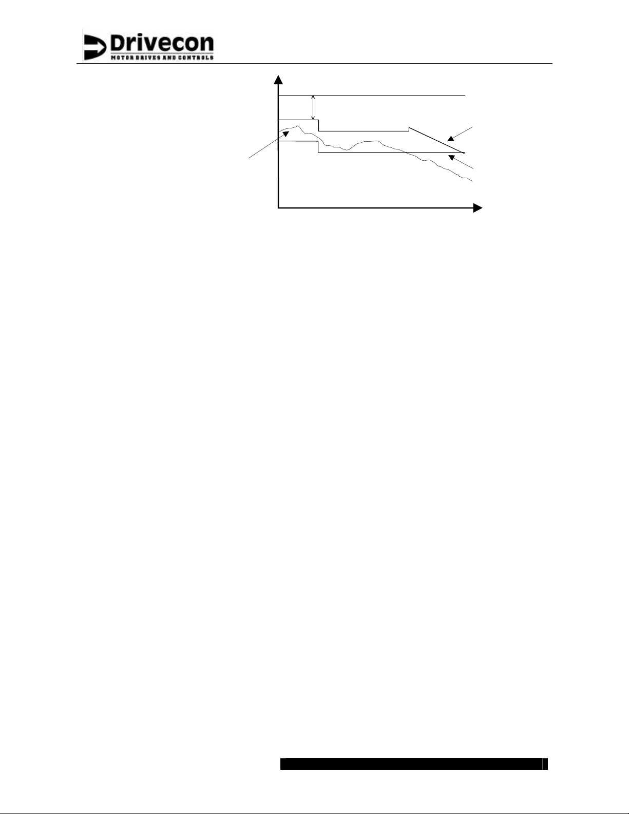
Interference
level
Page 15
Safety margin
Service Manual
Pro2V070
Immunity level of
second environment
Emission limit of
second environment
Typical emission
of D2H/D2C
Emission limit of
first environment
Frequency
Drivecon Inc. reserves the right to alter or amend the above information without notice 21.12.2004 • XT SERIESCSM55BEN
Page 16
Service Manual
Pro2V070
2 INSTALLATION
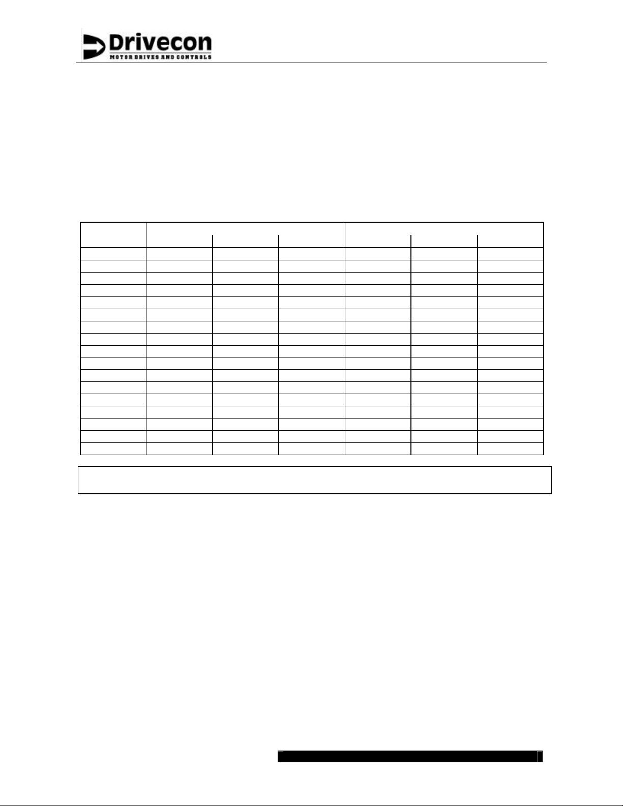
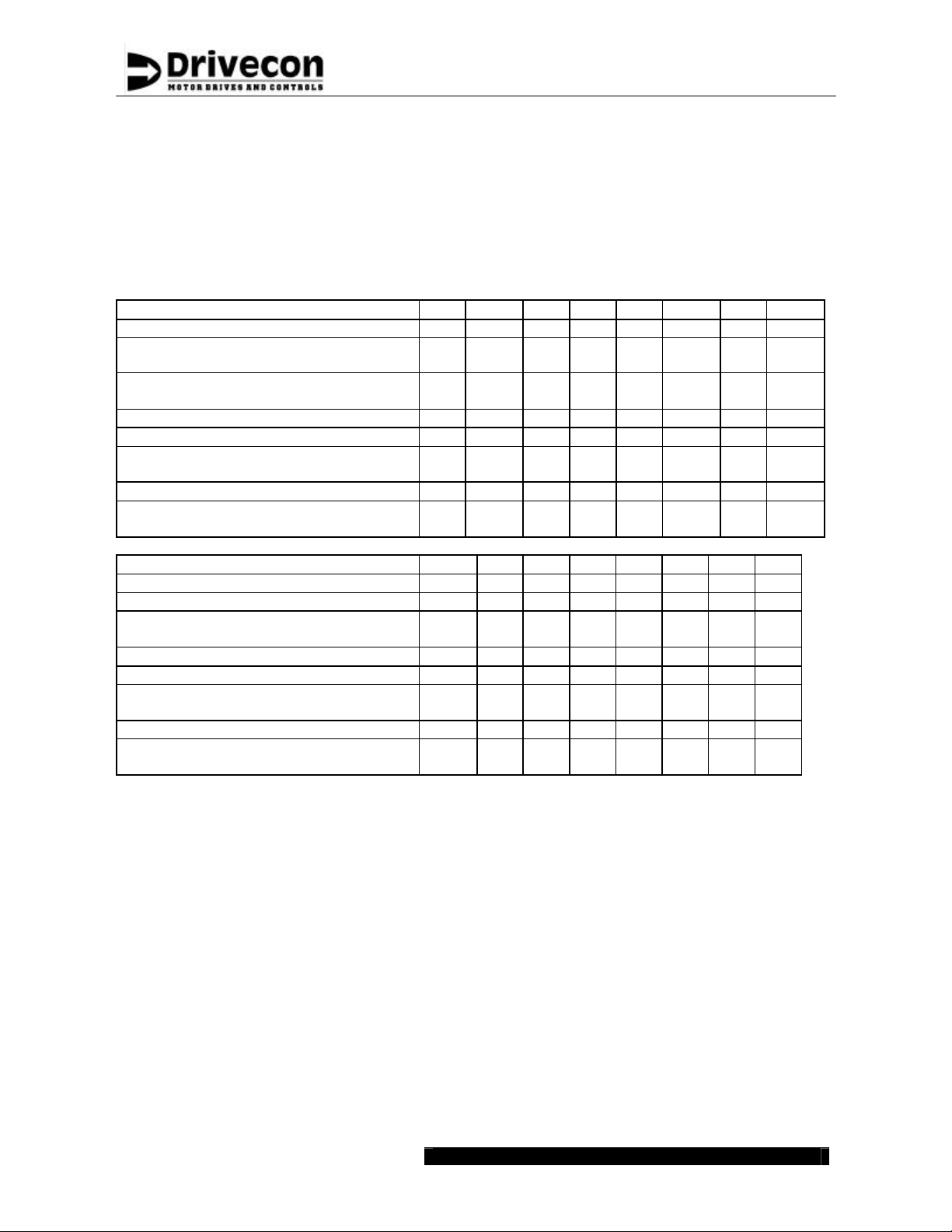
2.1 Cooling
The needs of cooling arrangements for the XT SERIES vary by application. The actual thermal
loading of the enclosure has to be estimated based on the loading conditions and duty cycles. The
power losses of XT SERIES are listed in the below table for each power rating. In most cases, XT
SERIES models up to 132F do not require any special cooling arrangements as the main part of
the losses is fed outside the cubicle in standard installations. Cooling for models, which are
installed in totally closed cubicles, is required to be checked case by case.
Through panel mounted Totally enclosed cubicle
Model ED40 ED60 ED100 ED40 ED60 ED100
002F 21 24 29 67 92 141
003F 20 22 25 53 70 104
004F 21 23 28 64 87 132
005F 24 28 36 96 134 211
007F 25 30 39 116 160 248
011F 31 39 54 176 250 398
015F 30 37 51 177 246 383
018F 38 49 71 256 364 581
022F 41 54 79 289 413 662
030F 34 43 60 230 318 493
037F 43 57 83 322 456 724
045F 53 71 107 415 596 957
055F 54 72 108 570 749 1108
075F 73 101 156 763 1039 1591
090F 89 125 197 927 1284 1999
110F 73 101 157 1013 1291 1845
132F 89 125 196 1170 1526 2237
Note! The power losses given above do not include the power fed to the braking
resistors.
2.2 Power cabling
Shielded
motor cable
Double
collectors
Drivecon Inc. reserves the right to alter or amend the above information without notice 21.12.2004 • XT SERIESCSM55BEN
In crane application, XT SERIES fulfills EN61800-3/A11 (IEC 1800-3) second
environment radiated emission requirements without shielded motor cable.
However shielded motor cable is recommended to use in fixed installations,
especially in buildings.
In the second environment, shielded motor cable is recommended to use in fixed
installations, especially in buildings. However motor cables in crane and festoon
power supplies are normally not shielded due to the practical reasons.
Shielded motor cable is essential to use if installation is requested to fulfill the
first environment emission requirements.
If the power is supplied to the crane via conductor rails, double collectors are
needed. This ensures a reliable contact with the rail in all circumstances. Short
interruptions and sparks between the conductor rail and the collector may cause
nuisance tripping, other undesired operations and in worst case even permanent
damage to components.
Page 17
Service Manual
Pro2V070
Cable
selection
Cabling for XT SERIES can be done using normal crane cables. All the cables
must be dimensioned according to local regulations. Ambient temperature, cabling
method (size of bunches etc.) and allowable current for the cable in use must be
taken into consideration. If there are no other regulations, following values can be
used (three phase 400V supply).
The table below is based on rated continuous current and ambient temperature
+40? C (104?F). A higher ambient temperature may require increased cable sizes.
If the actual load current is below XT SERIES continuous current, then the fuses
and the supply cable may be dimensioned according to the load current.
Power class 002 004 005 007 011 015 018 022
Continuous current I
Fuse/MSP A
Max motor cable
length
A 5.6 9 12 16 23 31 38 46
CONT
6.2
11.25 15 20
5
27.
5
38.75
47.
5
m 50 50 50 50 50 50 50 50
56.25
Ft 160 160 160 160 160 160 160 160
Motor cable
Braking resistor cable
o
104
104
AWG 14 14 14 14 14 10 8 8
F
o
F
AWG
14 14 14 14 14 14 10 8
Power class 030 037 045 055 075 090 110 132
Continuous current I
A 61 72 87 105 140 170 205 245
CONT
Fuse A 80 90 110 125 175 225 250 300
Max motor cable
length
m 50 50 75 75 75 75 100 100
Ft 160 160 240 240 240 240 325 325
Motor cable
Braking resistor cable
104
F
104
F
o
AWG
o
AWG
6 5 4 3 1/0 2/0 3/0 3/0
6 4 3 2 1/0 1/0 2/0 3/0
Cable
protection
To protect the supply cables against short circuit there must be fuses or motor
circuit breakers (MCCBs) installed at the mains end of the supply cable.
Dimensioning of the fuses or MCCBs depends on the cable used and on the type
of primary fuses or MCCBs. If there are no other regulations, the values given in
this section can be used to dimension fuses (three phase 400V supply).
The overload protection of XT SERIES protects both the supply and the motor
cables. The fuses of the supply provide the short circuit protection.
Drivecon Inc. reserves the right to alter or amend the above information without notice 21.12.2004 • XT SERIESCSM55BEN

?
?
Cable
length
Note! All control cables must be placed as far from the motor and braking resistor
The maximum motor cable lengths in the preceding table are based on 150% of
inverter rated current (=current during acceleration) and a 2.5 % voltage drop in
the cable. For longer cables, the required conductor cross sectional area A (mm2)
is given by formula
A
? ?
where
p
U
cables as possible.
24315.
l I
p U
is the cable length (m)
l
is the motor current (A) at shaft power
I
F
is the allowed voltage drop in %
is the nominal motor voltage
Page 18
.
?
F
Service Manual
Pro2V070
P
F
Drivecon Inc. reserves the right to alter or amend the above information without notice 21.12.2004 • XT SERIESCSM55BEN

Page 19
Service Manual
Pro2V070
2.3 Control wiring
Shielded signal cable
Reference signals
Sensor bearing
Encoder
Note! All shielded cables must be placed as far from the motor cables as possible
(>20cm). Shielding must be continuous. The "pigtail" (= the end to be connected)
of the shield should not be connected to minimize disturbances.
It's recommended to use twisted pair and braided shielded signal
cables. Foil type shield is not sufficient enough in crane applications
because of poor mechanical durability. Cable insulation material effects
the cable capacitance. Recommended cable capacitance between
signal-signal and signal -ground is equal or less than 100pF/m (31pF/ft).
It is not recommended to use shielded flat cable, because its
capacitance is extremely high and this may cause high frequency
interference.
Shielded round cables must be used for analog reference signals. The
shield is to be grounded only at XT SERIES (not at the other end of the
cable).
The cable for the sensor bearings must be shielded round cable and
grounded at both ends.
The encoder connections may be split into two cables, then the signal
conductors (4pcs) should go together in one cable and the supply and
common (+24V/0V) together in another cable. The encoder cable(s)
must be shielded round cable(s) and grounded at both ends.
2.4 EMC compatible grounding
Construction
connections
Cable connections
Shielded control
cables
All metal construction parts of the cubicle must be electrically
connected to each other using largest possible surface area. Paint to
paint connection must not be used.
Control cables and power cables should be separated and routed
separately for eliminating noise coupling. The distance between braking
resistor cables and the other cables should be kept as long as possible.
The distance between the resistor cables should be kept as low as
possible to prevent the antenna behavior. Cable lengths should be kept
as short as possible to minimize coupling capacitances and
inductances.
Shielded control cables should be grounded in both ends. The shield
must be connected to the ground using the largest possible surface
area. Extra intermediary terminators cutting the shield are not allowed;
the shield should maintain its integrity as much as possible. Spare
conductors should be grounded in the both ends.
Drivecon Inc. reserves the right to alter or amend the above information without notice 21.12.2004 • XT SERIESCSM55BEN

Page 20
Service Manual
Pro2V070
3 START-UP PROCEDURE
If any problems or malfunctions occur during the start-up, refer to Chapter “Troubleshooting”, to
find out the reason. All problems must be solved before continuing.
Warning! High voltages inside the device. Wait for at least five minutes after the supply
voltage has been switched off before doing any service actions. The display in
the operating condition (lights on) indicates a dangerous voltage on the DC-bus.
When display turns off, the DC -bus voltage is approximately 100V. Note also that
?? Do not connect any voltage to the output terminals (U, V, W). Otherwise, the inverter will be
dam aged.
?? The overload protection protects both the supply and the motor cables. The fuses of the supply
provide short circuit protection.
3.1 Visual checks
–
Record all checks and results.
–
Check condition of the cubicles.
–
Check that XT SERIES serial number is the same as in the delivery documents.
Check the switch settings on SSU (see chapter "SSU").
??
??
?? Check the cabling to the motor, brake, thermistors and speed sensor.
?? Check the motor type.
?? Check the wire terminations in the motor connection box
?? Check connections for motor, thermistors, heaters, brake wear and speed sensor circuits.
?? Disconnect motor (U, V, W) and brake cables to prevent damage of the inverter. Measure the
isolation resistance of the brake coil and the motor windings (each phase to ground).
?? Re-connect motor and brake cables.
?? Check braking resistor(s).
there is always a dangerous voltage in the braking resistor when the DC-bus is
charged.
If necessary, open the control box cover and adjust the SSU settings.
3.2 Checks before the first test run
Warning! High voltages inside the device.
?? Check the power supply voltage (nominal voltage +/- 10%).
–
Make sure that run commands are off ( pushbuttons / controller (master switch) at zero position).
?? Turn on the power from the main switch and the control voltage switch.
–
Within about 1 second the keypad should display "AC on", and then in about 1 second the
display changes to the multimonitor screen displaying “output voltage, current and frequency”
and the green READY status indicator turns on.
–
In a fault situation, the red FAULT status indicator blinks and the display shows a fault code
instead of frequency.
Check that the green RUN status indicator is off.
??
Check that the external connections and programming of digital inputs are according to the
??
application.
The parameters are properly set after factory tests and no adjustments are needed except for
??
the parameters that depend on the application and the motor. Write down in the parameter list
all the values that have been changed.
Drivecon Inc. reserves the right to alter or amend the above information without notice 21.12.2004 • XT SERIESCSM55BEN

Page 21
Service Manual
Pro2V070
3.3 Test run without load
?? See also chapter 4.4 Open Loop motor parameter adjustments and chapter 4.5 Closed Loop
motor parameter adjustments
?? Make sure that movement will not cause any danger to the environment or to the crane itself.
Avoid running close to the limit areas.
?? Check the limit switches manually if possible.
?? Check the run commands on the keypad display and correct the motor rotating direction. The
arrow rotates clockwise if S1 (fwd/up) is applied, and counter-clockwise if S2 (rev/down) is
applied.
Check the function of the speed sensor, see chapter “Speed sensors”
??
?? Check the function of the speed supervision circuit. See "Functional test run for SSU".
?? Run forward (upwards) at minimum speed for 5 to 10 seconds. Accelerate to full speed. Run 5
to 10 seconds. Stop. Repeat the same in the reverse (down) direction. Check the frequency
display to make sure that the frequency changes through the whole operational frequency range
from the minimum to the nominal speed.
Check the motor operation (acceleration, deceleration and braking): accelerate to full speed
??
forward (up), change to full speed reverse (down) and full speed forward (up) again and stop.
?? Check the limit switch functions: run forward (up) slowly and check the slowdown and the stop
limit switch operations. Re-check using full speed. Repeat the same check for the reverse
(down) direction.
?? If the optional ESR is used, check the maximum frequency.
3.4 Test run with load
?? See also chapter 4.4 Open Loop motor parameter adjustments and chapter 4.5 Closed Loop
motor parameter adjustments
?? Note, three loads are required:
?? Nominal load (100%) for normal operation.
?? Limited load for ESR (optional).
?? An adequate extra load for dynamic overload testing and to test the ESR load limit.
?? See the maintenance instruction HU1.03.0004 “Erection, Installation and Testing of EOT
cranes” for the details of the load tests.
–
Make sure that movement will not cause any danger to the environment or to the crane itself.
?? If the optional extended speed range (ESR) is used, check that the load limit is correctly set and
hoisting with bigger loads is prevented.
–
Run in both directions at minimum and maximum speeds.
?? If the fan tube resistor unit is included, check that the fan(s) starts to blow when running down
with nominal load and continues to blow for about 4-5 minutes after stopping.
3.5 After the test run
–
Record all the parameter value changes in the parameter list.
–
Make sure all remarks and setting values are recorded.
–
Copy all parameters up to keypad memory by parameter S6.3.2.
–
Save user parameters in Control Unit by parameter B4.1.2.
Drivecon Inc. reserves the right to alter or amend the above information without notice 21.12.2004 • XT SERIESCSM55BEN
Page 22
4 PARAMETER ADJUSTMENTS
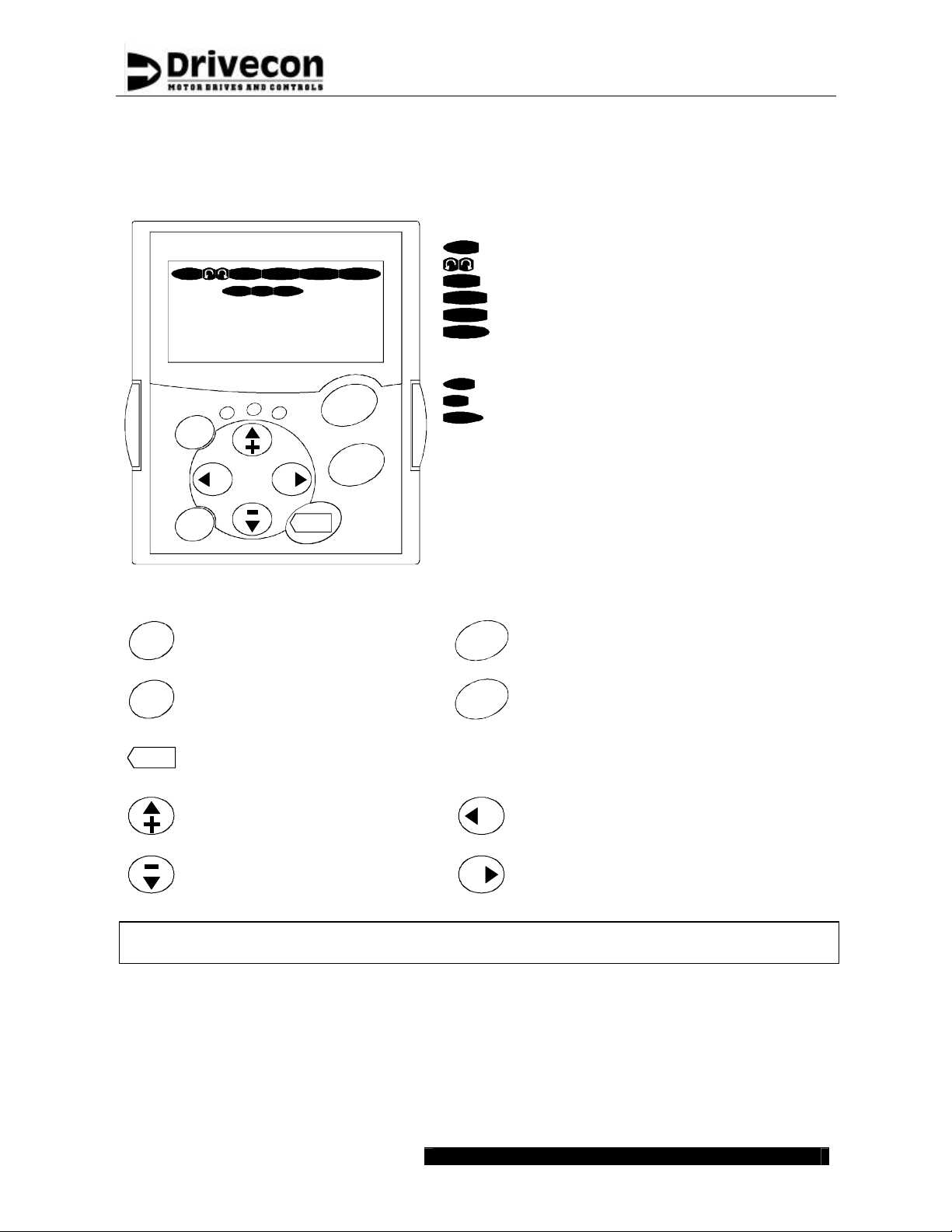
4.1 Control keypad operation
Drive status indications:
READY FAULTSTOPRUN
KeypadI/O term
P3.4.1.1.
Bus/Comm
Motor Nom Volt
400 V
run
ready
reset
select
Button descriptions :
fault
ALARM
enter
START
STOP
RUN
STOP
READY
ALARM
FAULT
Control place indications:
I/O term
Keypad
Bus/Comm
Text lines:
Line 1 Location indication (parameter number)
Line 2 Description line (parameter name)
Line 3 Value line (parameter value)
Status LEDs:
ready green Illuminates the AC -supply is on
run green Illuminates during run
fault red Illuminates due to fault tri p
Motor is running
Motor rotation direction
Inverter is not running
AC power is on
Warning is on
Fault is on
Terminals are the selected control place
Control keypad is the selected control place
Control through Profibus is selected
Service Manual
Pro2V070
reset
select
enter
Reset active faults
START
Switch between two latest
displays
Confirmation of selections
STOP
Browse up the menus
Increase values
Browse down the menus
Decrease values
Starts the motor if the keypad is the
active control location
Stops the motor if the keypad is the
active control location
Move to previous menu level
Move cursor left
Exit edit mode
Move to next menu level
Move cursor right
Enter edit mode
Warning! Running via keypad can cause a hazardous situation. Keypad cont rol must not be
used.
Drivecon Inc. reserves the right to alter or amend the above information without notice 21.12.2004 • XT SERIESCSM55BEN
Page 23
Service Manual
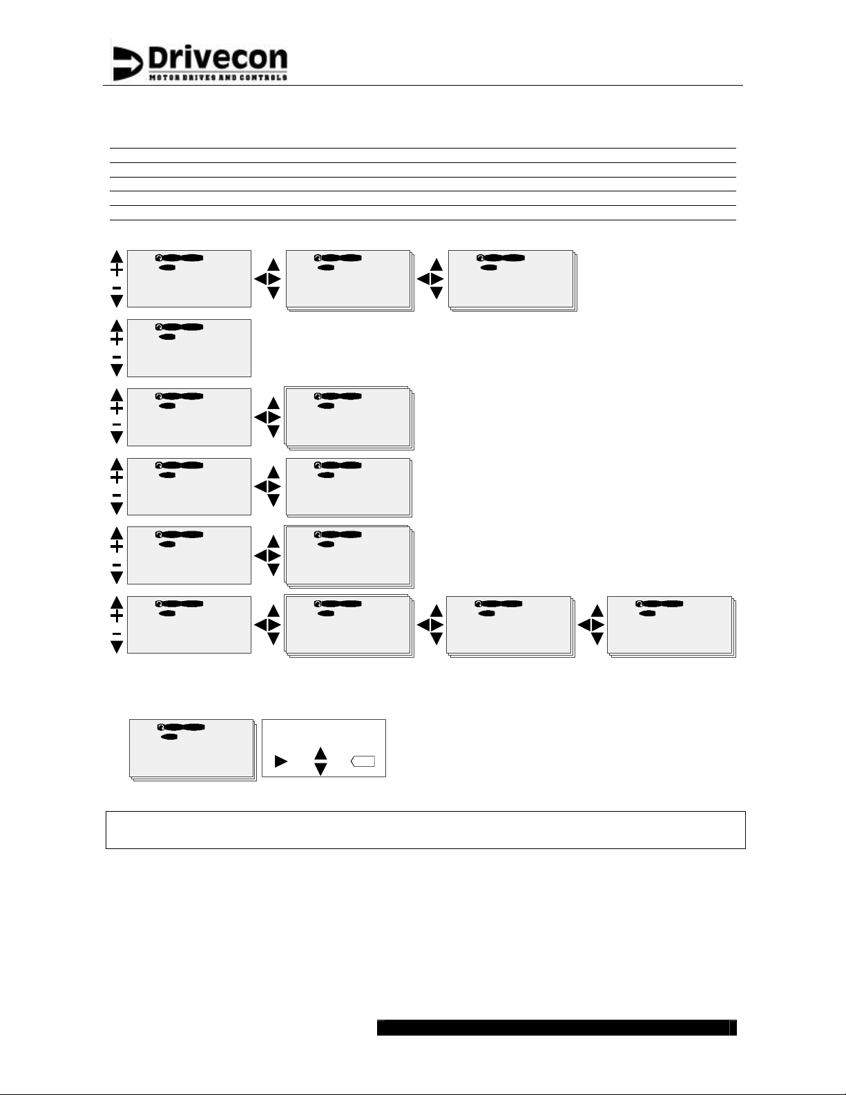
4.1.1 Navigation on the control keypad
Letter front of the code number describes variable type
B = Button G = Group N = Multimonitor T = Trip Counter
C = Counter H = Fault History P = Parameter V = Value
D = Data I = Info R = Reference
E = Expander M = Menu Group S = System
M8.
Fault History
H1?Hxx
READY
STOP
I/O term
M7.
?
H8.1.
57 Thermistor
F T1?T16
READYSTOP
I/O term I/O term I/O term
READYSTOP
T8.1.1.
READYSTOP
Operation days
?
0
Active Faults
F0
Pro2V070
M6.
System Menu
S1?S8
READY
STOP
I/O term I/O term
G5.
?
Panel Control
B1?R2
READYSTOP
I/O term I/O term
G4.
?
Monitoring
G1?G23
READYSTOP
I/O term I/O term I/O term I/O term
G3.
?
Parameters
G1?G9
?
S6.2.
Application
Crane
B5.1.
Panel Control
Off
V4.22.
Output Frequency
0.00 Hz
G3.4.
Motor Parameters
G1?G7
READYSTOP
I/O term I/O term
STOP
READYSTOP
READY
READYSTOP
READYSTOP
?
G3.4.1.
READYSTOP
Motor Set 1
P1?G23
?
P3.4.1.1.
READYSTOP
Motor Nom Volt
400 V
4.1.2 Value line editing
P3.4.1.1.
Motor Nom Volt
400 V
Warning! Changing parameter settings during running may cause a hazardous situation.
READYSTOP
I/O term
Mode
change
Edit
value
Accept
value
enter
Parameter settings must not be changed during running.
Drivecon Inc. reserves the right to alter or amend the above information without notice 21.12.2004 • XT SERIESCSM55BEN

4.1.3 Passwords
Parameter Name Description
P3.1. 1 Password
Following passwords release the parameter locks.
Level 1 Locked 0
Level 2 Start-up 26
Level 3 Engineering 768
4.1.4 Special button functions
Button Time delay Description
Page 24
Service Manual
Pro2V070
START
select
reset
enter
> 2 seconds Password level changes to Level 3 Engineering.
> 2 seconds Displays the software version.
> 2 seconds Display changes straight to adequate autotuning parameter.
> 2 seconds Changes display straight to V4.22 Output Frequency.
> 3 seconds Resets whole H8 Fault History when display in any level of H8 menu.
> 1 second Resets whole H8 Fault History when display in sublevel of H8 menu.
Drivecon Inc. reserves the right to alter or amend the above information without notice 21.12.2004 • XT SERIESCSM55BEN
G4.1
Parameter Backup
G4.7
Digital Input
G4.7.1
DI Status
G4.1.4
Factory default
G4.2
Analog I/O
G4.3
Relay Output
G4.7.2
DI Function
G4.4
Operate Counters
G4.5
Fault Counter
G4.8
SSU
G4.9
Service
G4.6
Bus Control
G4.9.10
Max Current
G4.10
Sway control
G4.23
Multimonitor
Page 25
Service Manual
Pro2V070
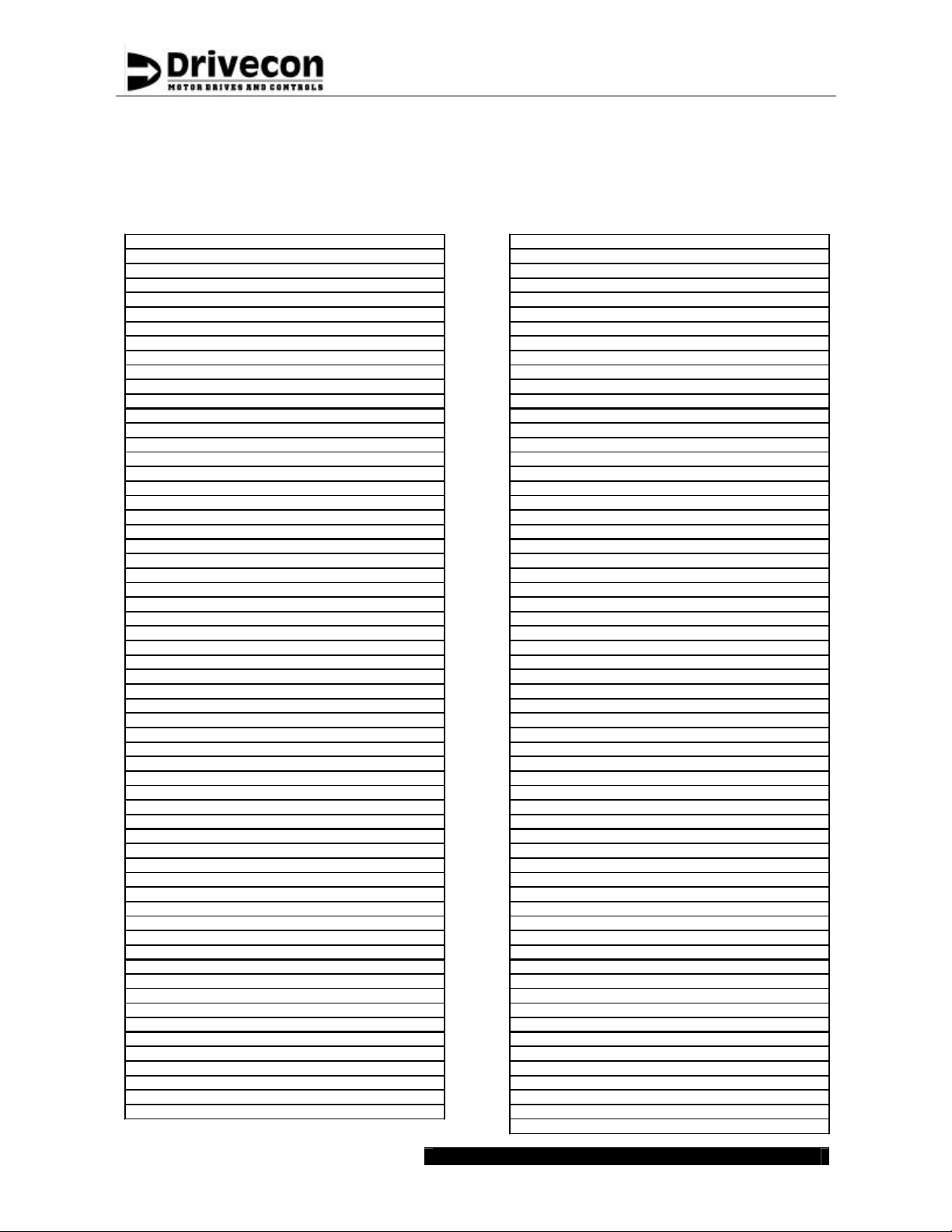
4.1.5 Monitoring
Below are listed the parameters of Group G4 Monitoring. For example, operation of analog and
digital inputs can be verified with monitoring parameters. After power off and on the display returns
as default to V4.22 Output Frequency.
B4.1.1 Load Default Par
B4.1.2 Save User Par
B4.1.3 Load User Par
B4.1.4 Save Default Par
V4.2.1 Ain1 Value V V4.7.1.6 OK
V4.2.2 Ain2 Value V V4.7.1.7 DID1
V4.2.3 Aout1 Value mA V4.7.1.8 DID2
V4.2.4 Aout2 Value V V4.7.1.9 DID3
V4.3.1 ROB1 State V4.7.1.11 DID5
V4.3.2 ROB2 State K7
V4.3.3 ROC1 State V4.7.2.1 DIA3 Function
V4.3.4 ROD1 State V4.7.2.2 DIA4 Function
V4.3.5 ROE1 State V4.7.2.3 DIA5 Function
V4.3.6 ROE2 State V4.7.2.4 DID1 Function
V4.3.7 ROE3 State V4.7.2.5 DID2 Function
V4.4.1 Motor MWh MWh V4.7.2.7 DID4 Function
V4.4.2 Generator MWh MWh V4.7.2.8 DID5 Function
V4.4.3 Start Counter x 1k V4.7.3 Basic Board
V4.4.4 MotorRuntime (h) h V4.7.4 Extension Board
V4.7.1.1 S1
V4.7.1.2 S2
V4.7.1.3 DIA3
V4.7.1.4 DIA4
V4.7.1.5 DIA5
V4.7.1.10 DID4
V4.7.2.6 DID3 Function
R4.5.1 Fault Counter V4.8.1 Overspd Lim 1 %
V4.5.2 Total Faults V4.8.2 Overspd Lim 2 %
V4.5.3 Selected Faults
V4.9.1 Phase U Curr A
V4.6.1 S1 V4.9.2 Phase V Curr A
V4.6.2 S2 V4.9.3 Phase W Curr A
V4.6.3 Motor Set 2 V4.9.4 Encoder Speed Hz
V4.6.4 Second Speed Lim V4.9.5 HeatSinkTempMax °C
V4.6.5 Field Weakening V4.9.6 HeatSinkTempMin °C
V4.6.6 Alt Control Mode V4.9.7 IGBT Temp Max °C
V4.6.7 Brake Feedback V4.9.8 IGBT Temperature °C
V4.6.8 Ramp 2 V4.9.9 SlipAdjustChange %
V4.6.9 Torque Limit
V4.6.10 AP V4.9.10.1 Max Current
V4.6.11 Slow Limit S11 V4.9.10.2 Max Current Freq
V4.6.12 Slow Limit S21 V4.9.10.3 Max Current Torq
V4.6.13 End Limit S12
V4.6.14 End Limit S22 V4.10.1 Swing Time s
V4.6.15 Brake Pedal V4.10.2 Pendulum Length m
V4.6.16 S-Curve Inhibit V4.10.3 StoppingDistance m
V4.6.17 Tare V4.10.4 Sway Ctrl Status
V4.6.18 Inching V4.10.5 License Status
V4.6.19 SlackCableByPass V4.10.6 DemoLicenseTime
V4.6.20 Brake Pedal 2 V4.11 Freq Ref Hz
V4.6.21 Synchronizing V4.12 Speed Req Hz
V4.6.22 Speed Reference Hz V4.13 Distance Counter m
V4.6.23 Torque Reference % V4.14 DC-link Voltage V
V4.6.24 Speed Correction Hz V4.15 Heat Sink Temp °C
V4.6.25 Ramp Reference V4.16 MotorTemperature %
V4.6.26 Torque Limit Ref % V4.17 Motor Power %
V4.6.27 Speed Limit Ref V4.18 Motor Voltage V
V4.6.28 Load Feedback V4.19 Motor Torque %
V4.6.29 Sway Ctrl Height V4.20 Motor Current A
V4.6.30 Calibration Pos V4.21 Motor Speed rpm
V4.6.31 Profibus Status V4.22 Output Frequency Hz
V4.6.32 Bus Cycle Time ms
N4.23.1 Multimonitor
Drivecon Inc. reserves the right to alter or amend the above information without notice 21.12.2004 • XT SERIESCSM55BEN
Page 26
Service Manual
Pro2V070
4.2 Input selections
Digital inputs are programmed based on function. Each function can be set to one of the 8
programmable digital inputs. The programmable digital inputs are DIA3, DIA4, DIA5, DID1, DID2,
DID3, DID4 or DID5.
There are also 3 other inputs, which functions cannot be changed by parameters. These nonprogrammable inputs are OK-input and the direction signals S1 and S2.
In basic applications one function is set to certain input. For special applications it is also possible
to set many functions to same input.
Example: Torque limit and Ramp2 should be activated with DIA5. Select the value 3=DIA5 in both
parameters P3.2.1.7 and P3.2.1.8.
Note! Impossible function combinations may be selected.
In following table are listed the possible inputs for each function.
Parameter Name / Function DIA3 DIA4 DIA5 DID1 DID2 DID3 DID4 DID5
P3.2.1.1 Motor Set 2 X X X X X X X X
P3.2.1.2 SSL X X X X X X X X
P3.2.1.3 ESR X X X X X X X X
P3.2.1.4 Micro Speed Sel X X X X X X X X
P3.2.1.5 Alt Control Sel X X X X X X X X
P3.2.1.6 Profibus Control - - X - - - - P3.2.1.7 Ramp2 X X X X X X X X
P3.2.1.8 Trq Limit X X X X X X X X
P3.2.1.9 AP X - - - - - - P3.2.1.10 CMS - X - - - - - P3.2.1.11 EP-Hold X X X X X X X X
P3.2.1.12 Multistep2 X X - - - - - P3.2.1.13 Multistep3 - X X - - - - P3.2.1.14 Multistep4 - - X X - - - P3.2.1.15 Multistep5 - - - X X - - P3.2.1.16 PO/MS
P3.2.1.17 S11 - - X - X - - P3.2.1.18 S21 - - - X - X - P3.2.1.19 S11 & S21 X X X X X X X X
P3.2.1.20 S12 - - - - X - X P3.2.1.21 S22 - - - - - X - X
P3.2.1.22 MF1 Input X X X X X X X X
P3.2.1.24 MF2 Input X X X X X X X X
X X X X X X X X
Drivecon Inc. reserves the right to alter or amend the above information without notice 21.12.2004 • XT SERIESCSM55BEN
 Loading...