

Page 1
DC3 Video Event Recorder
with Safety Enhancement Mode Installation Instructions
Installation of the event recorder is not complicated, but care must be taken to ensure successful
operation. Follow these instructions carefully to ensure proper orientation and operation.
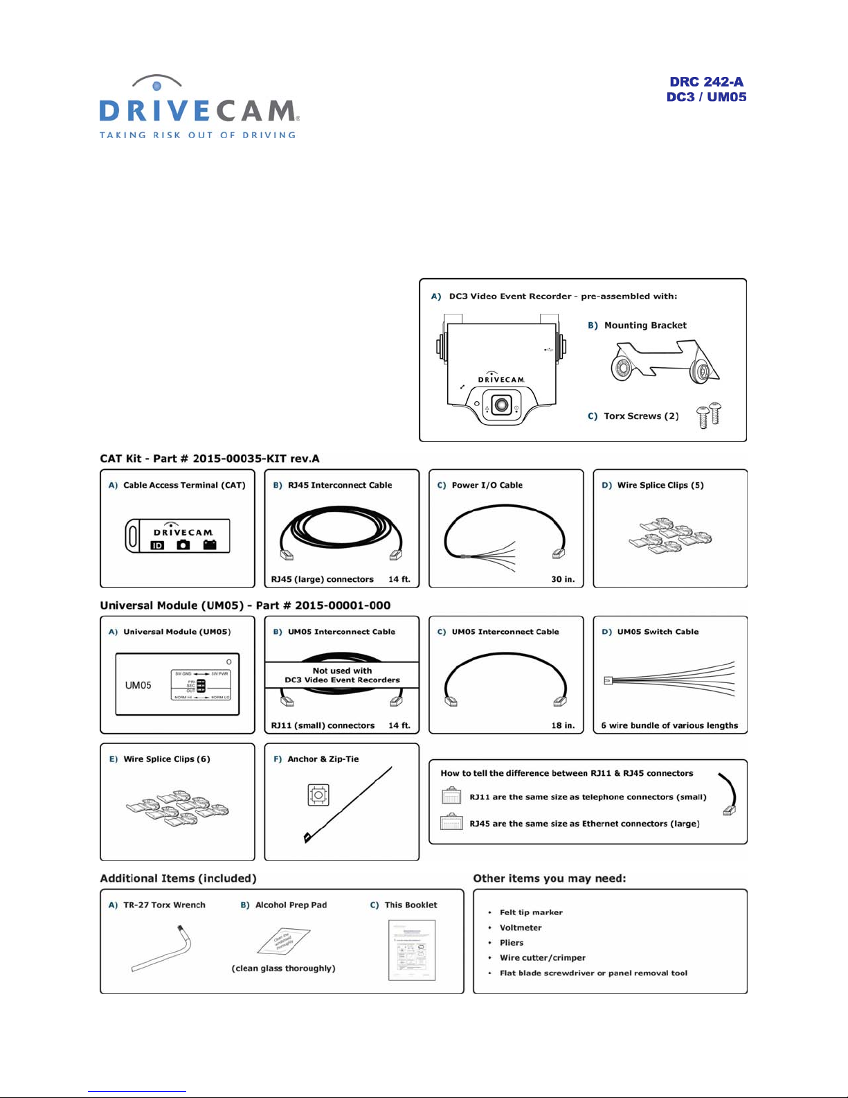
1.
Check the contents
of the installation kits
DRC 242-A 2007-08-03 Page 1 DC3 with SEM Installation Instructions
Page 2
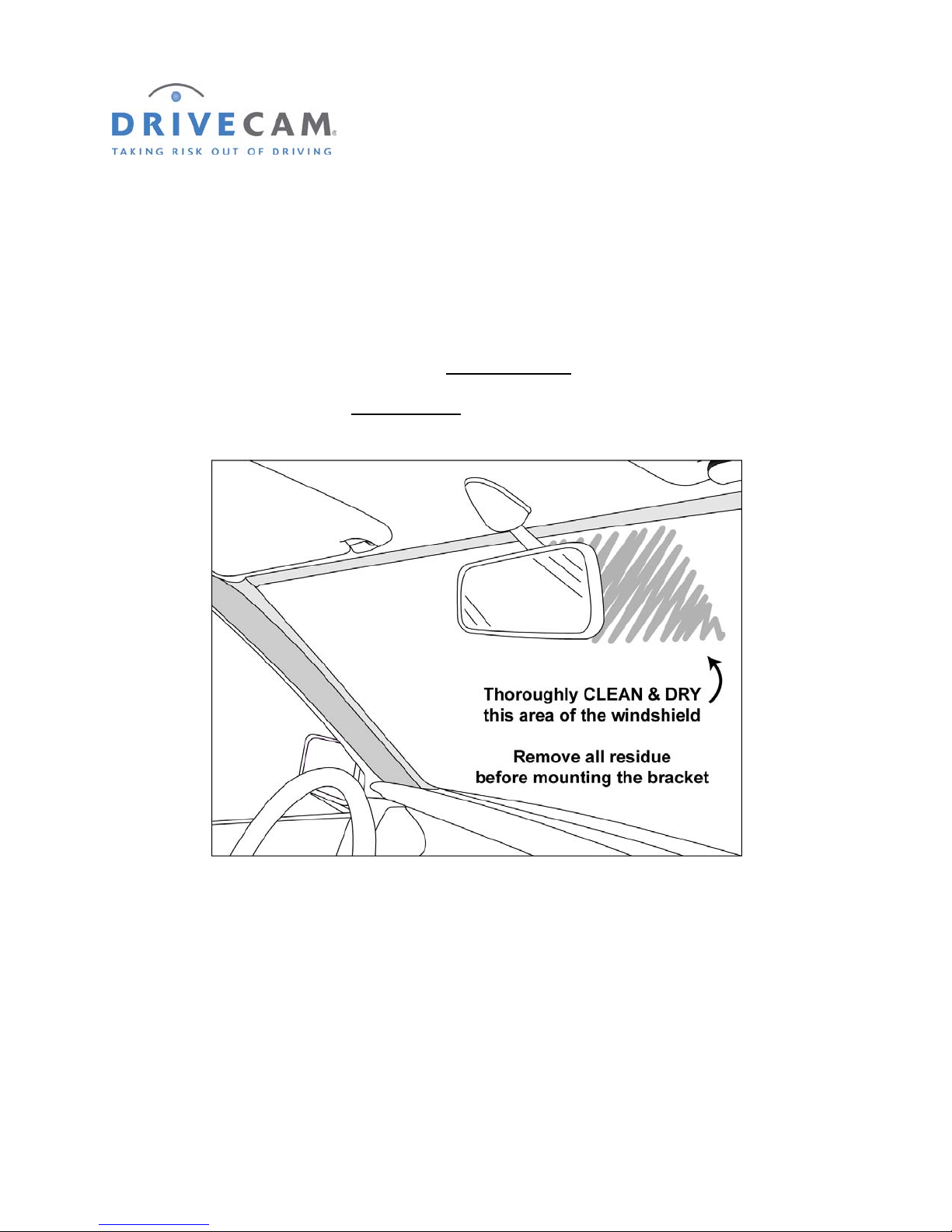
2. Thoroughly clean and dry the glass
CAUTION: This step is critical to prevent the bracket from falling off at a later date.
Step 1 Select a mounting location on the windshield behind the rear view mirror
on the passenger side of the vehicle.
Step 2 Using the alcohol prep pad provided, thoroughly clean
Step 3 Using a clean, dry cloth, thoroughly dry
the mounting area.
the mounting area.
DRC 242-A 2007-08-03 Page 2 DC3 with SEM Installation Instructions
Page 3
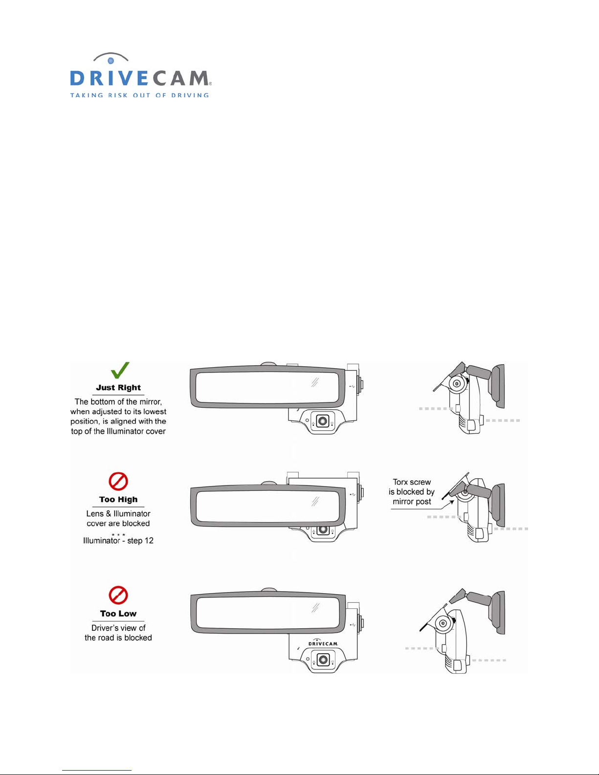
3. Carefully select the mounting location
The event recorder needs to be mounted in a location that provides an unobstructed view of the interior
and exterior (front) of the vehicle.
CAUTION: Do not peel the backing from the adhesive strip until instructed to do so.
Step 1 Loosen the Torx screws so the event recorder can rotate in the bracket.
Step 2 Pull the mirror down to its lowest position.
Most rear view mirrors can be adjusted up or down. Before selecting the mounting location,
adjust the mirror all the way down so that it can never cover the lens after mounting.
Step 3 Position the assembly behind the mirror, about one inch to the right of the post to allow
easy access to the Torx screw and power connection.
DRC 242-A 2007-08-03 Page 3 DC3 with SEM Installation Instructions
Page 4
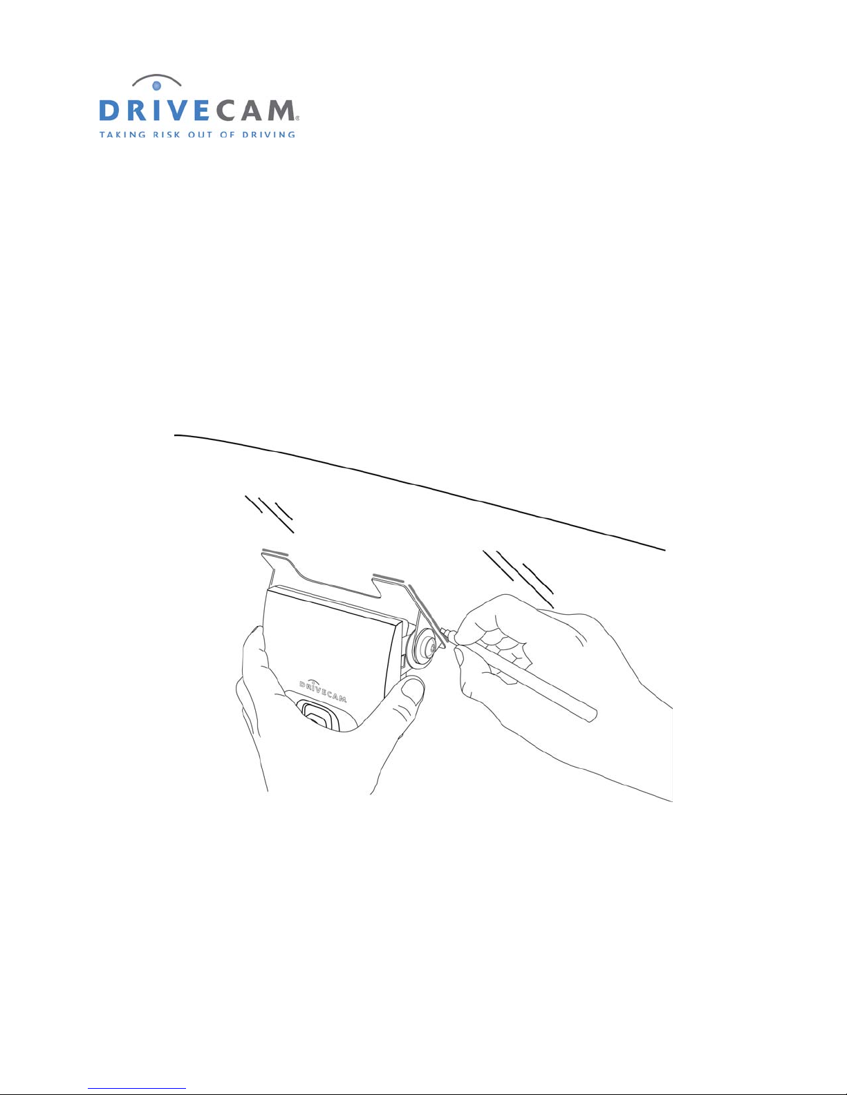
4. Mark the selected mounting location on the glass
Step 1 When you have selected the best mounting location, hold the assembly in place and trace
the outline of the bracket on the windshield with a felt tip marker.
Step 2 Make sure the traced guide marks are level before proceeding.
Step 3 Remove the event recorder from the mounting bracket.
Step 4 Check the fit of the bracket against the windshield.
If the windshield is curved, gently bend the bracket so that it will lie flush against the glass.
DRC 242-A 2007-08-03 Page 4 DC3 with SEM Installation Instructions
Page 5
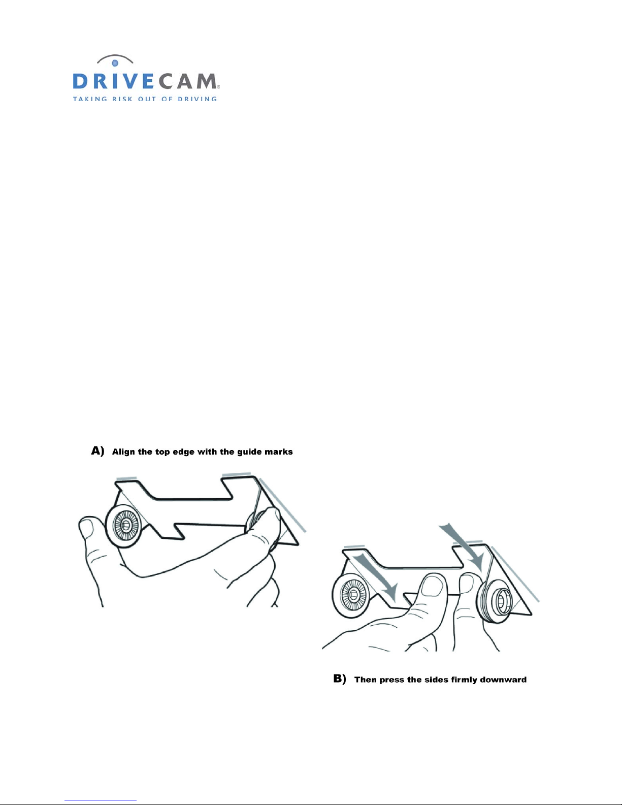
5. Attach the mounting bracket to the windshield
CAUTION: The adhesive is very sticky. Once applied to the windshield, it will not easily
come off. See page 25 for bracket removal instructions.
Step 1 Make sure
Step 2 Remove the backing from the adhesive side of the bracket.
Step 3 Start by placing only the top edge of the bracket against the windshield,
aligned with the guide marks, and make sure it is level.
Step 4 Press the bracket firmly against the windshield starting at the top
and pressing the sides downward.
Do not apply excessive pressure as it may cause the windshield to break.
Step 5 Make sure there are no large air bubbles under the bracket.
You may need to (carefully) apply additional pressure to the bracket and remove any large air
bubbles. Use a small pin to create an escape path for the air if the problem is persistent.
the glass is clean and dry and the air temperature is at least 50°F (10°C).
DRC 242-A 2007-08-03 Page 5 DC3 with SEM Installation Instructions
Page 6
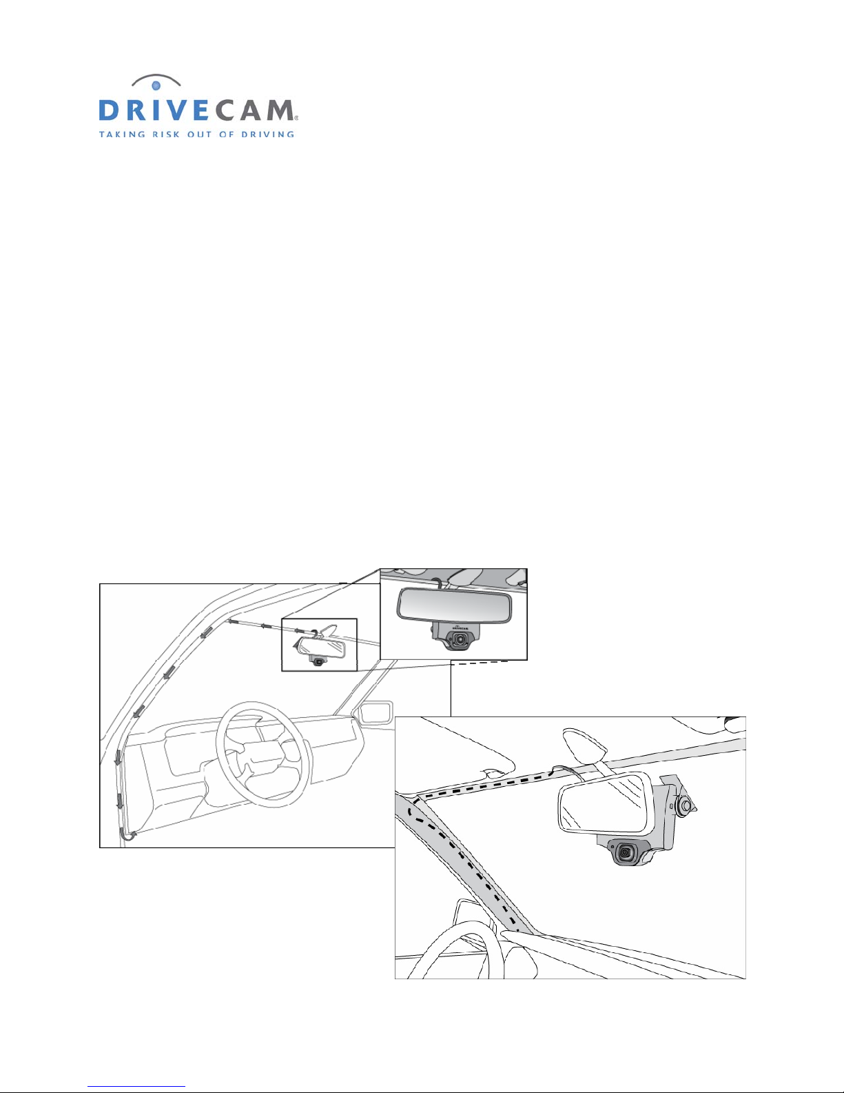
6. Route the RJ45 Interconnect Cable
CAUTION: When installing the RJ45 Interconnect Cable in a vehicle with side or curtain airbags,
be certain that neither the cable, nor your installation activities, interferes with any
airbag related mechanisms or otherwise affects airbag deployment.
NOTE: If you plan to connect the primary trigger input to the dome light (page 11), you
may want
Interconnect Cable at this time.
Step 1 Starting just above the rear view mirror, route the cable under the window trim or
headliner across to the door pillar.
Step 2 Route the cable down the door pillar underneath the vertical door / window trim.
Step 3 Route the cable out from underneath the trim and under the dashboard.
You may need to remove the trim to route the cable. When reinstalling, be careful not to damage
the trim clips or the cable. Keep the cable clear from sharp edges and moving parts.
to route the white wire from the UM05 Switch Cable along side the RJ45
DRC 242-A 2007-08-03 Page 6 DC3 with SEM Installation Instructions
Page 7
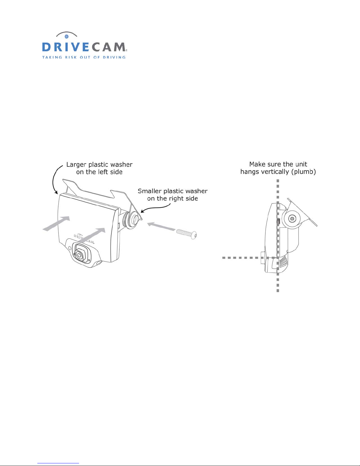
7. Mount the event recorder in the bracket
Step 1 Plug the RJ45 Interconnect Cable into the event recorder.
Step 2 Place the event recorder in the bracket.
Step 3 Adjust the event recorder so that it hangs vertically (plumb).
Step 4 Secure the event recorder in the bracket using the 2 Torx screws and Torx wrench.
The Large Plastic Washer on the left side of the bracket is designed to partially cover the RJ45
Interconnect cable so that it cannot be unplugged by the driver. The plastic washers can be easily
removed from the metal bracket after removing the screws. Make sure the larger of the two washers is
on the left (power connection) side of the bracket.
DRC 242-A 2007-08-03 Page 7 DC3 with SEM Installation Instructions
Page 8
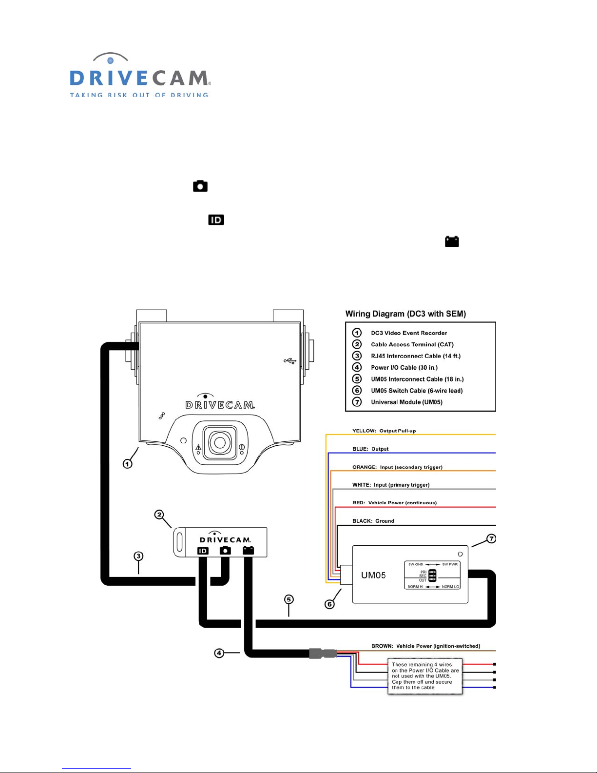
8. Wiring Diagram (DC3 with SEM Installation)
The RJ45 Interconnect Cable is 14 feet long with RJ45 (large) connectors at each end. One end of
the cable plugs into the event recorder. It is then routed to a secure location under the dashboard and
plugged into the middle port
The UM05 Interconnect Cable is 18 inches long with RJ11 (small) connectors at each end. One end of
the cable plugs into the left port
of the Cable Access Terminal (CAT).
of the CAT. The other end plugs into the Universal Module (UM05).
The Power I/O Cable is 30 inches long. One end of the cable plugs into the right port
the other end of the cable is a brown wire which connects to an ignition-switched power source.
The UM05 Switch Cable varies in length. One end of the cable plugs into the UM05. At the other end of
the cable are six wires which connect to vehicle power, ground, inputs and output (optional).
of the CAT. At
DRC 242-A 2007-08-03 Page 8 DC3 with SEM Installation Instructions
Page 9

9. Plug the cables into the CAT and UM05
The best place to keep the Cable Access Terminal (CAT) and the Universal Module (UM05) is usually
under the dashboard. Find a suitable location to connect and secure the wiring and equipment.
Step 1 Plug all cables into the Cable Access Terminal (CAT).
Step 2 Plug the UM05 Interconnect Cable into the Universal Module (UM05).
Step 3 Plug the UM05 Switch Cable into the Universal Module (UM05).
Do not secure the CAT or UM05 permanently in place until after the connec tions have been tested.
DRC 242-A 2007-08-03 Page 9 DC3 with SEM Installation Instructions
Page 10
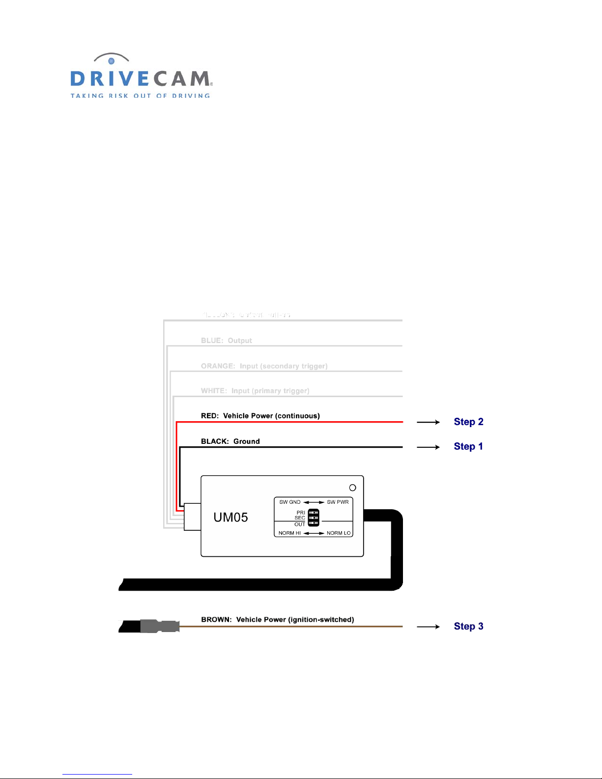
10. Connect the red, brown & black wires
These are the 3 required connections for the event recorder to function. The red wire provides primary
power and must be connected to a continuous power source. The brown wire is an ignition sense. It is
used by the event recorder to perform functions such as activating the IR Illuminator (see page 13) when
the vehicle ignition is switched on. The black wire is ground.
Step 1 Connect the BLACK WIRE to negative or to a clean GROUND.
Step 2 Connect the RED WIRE to a 12V or 24V fused power source that is ALWAYS ON.
Step 3 Connect the BROWN WIRE to a 12V or 24V fused power source that is IGNITION–S WITCHED.
DRC 242-A 2007-08-03 Page 10 DC3 with SEM Installation Instructions
Page 11
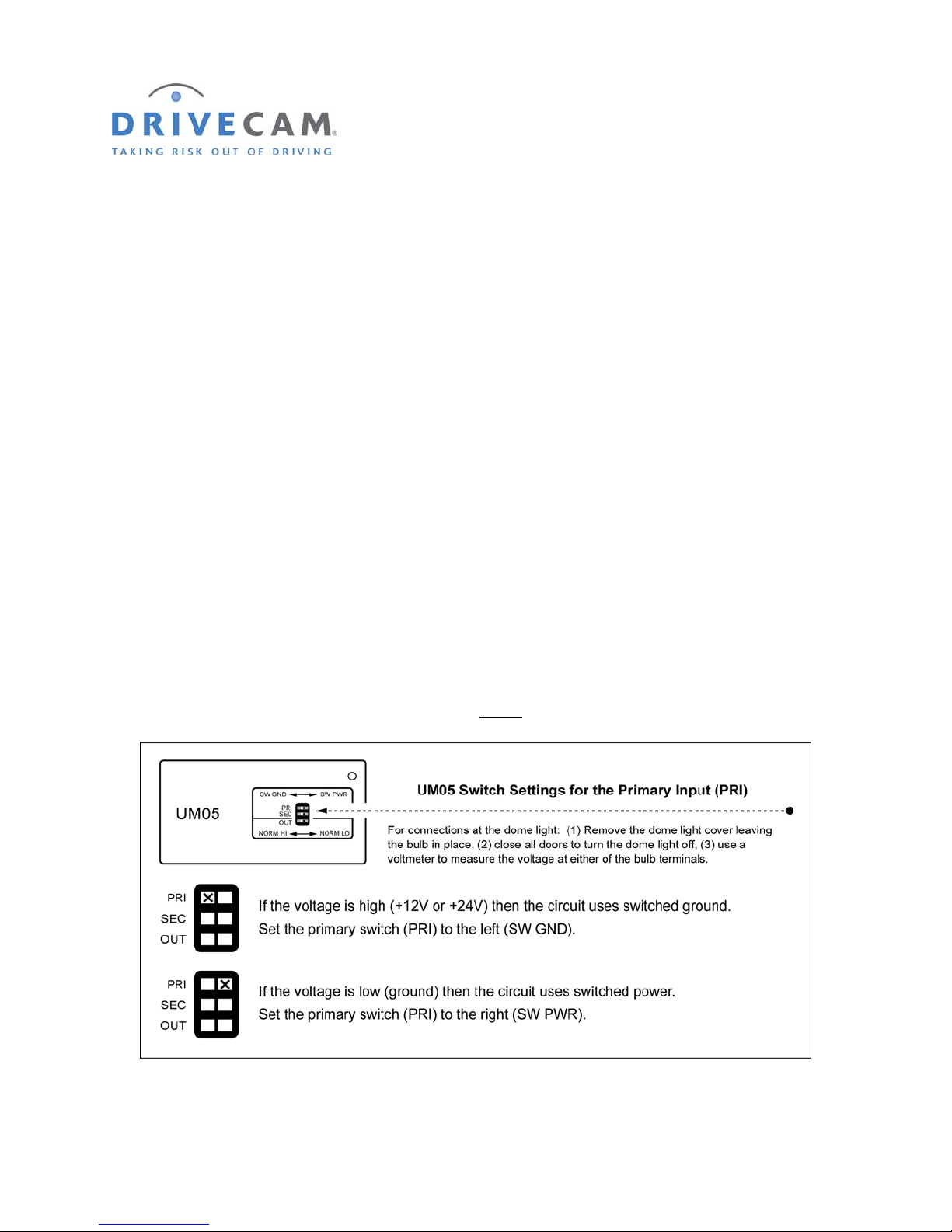
11. Connect the white wire (primary trigger input)
The primary trigger input (WHITE WIRE) is typically set up to monitor the vehicle’s doors. The
event recorder will then record an event each time a door is opened or closed. In many cases, the dome
light circuit is the best place to make this connection as it is usually connected to all of the vehicle’s doors.
If you can find the location of the dome light circuit under the dashboard, you’ll save yourself the trouble
of routing the wire under the headliner. If not, then you can simply make the connection at the dome light.
Some vehicles use a common door switch circuit (connecting all doors and the dome light) while other
vehicles use an individual door switch circuit (connecting each door to a controller and the controller to
the dome light). Refer to your vehicle’s wiring schematics for more information. If you’re not sure, make
the connection at the dome light.
Testing the Dome Light Circuit
Use the following steps to determine the type of bulb circuit (switched ground or switched power) and
make the appropriate primary (PRI) switch setting on the Universal Module (UM0 5).
Step 1 Remove the dome light cover, leaving the bulb in place.
Step 2 Turn the load “OFF” (i.e. close all doors to turn off the dome light).
Step 3 Use a voltmeter to measure the voltage at either
of the bulb terminals.
Step 4 Turn the load “ON” (i.e. open a door to turn on the dome light).
DRC 242-A 2007-08-03 Page 11 DC3 with SEM Installation Instructions
Page 12

Step 5 Use a voltmeter to measure the voltage at each of the bulb terminals.
One terminal voltage will remain the same as measured in step 3 – the other terminal voltage will
have changed. The connection must be made to the terminal that changed voltage.
Connecting the White Wire to the Dome Light Circuit
The best place to keep the UM05 is usually under the dashboard. This may require several feet of wire be
routed up the window trim (typically along side the RJ45 Interconnect Cable) and under the headliner to
the dome light.
Step 6 Unscrew the dome light fixture from the ceiling to expose its wiring and to provide an
entry point under the vehicle headliner.
Step 7 Route the length of white wire from the location where you will mount the UM05 (e.g. under
the dashboard) to the dome light.
A coat hanger can often be used to “hook and pull” the wire under the headline r.
Step 8 Connect the white wire to the dome light wire using the wire splice clips provided.
Make sure you are connecting to the correct side of the dome light circuit as measured in step 5.
Wait until after you have tested the primary trigger on page 16 before finalizing the connections.
DRC 242-A 2007-08-03 Page 12 DC3 with SEM Installation Instructions
Page 13
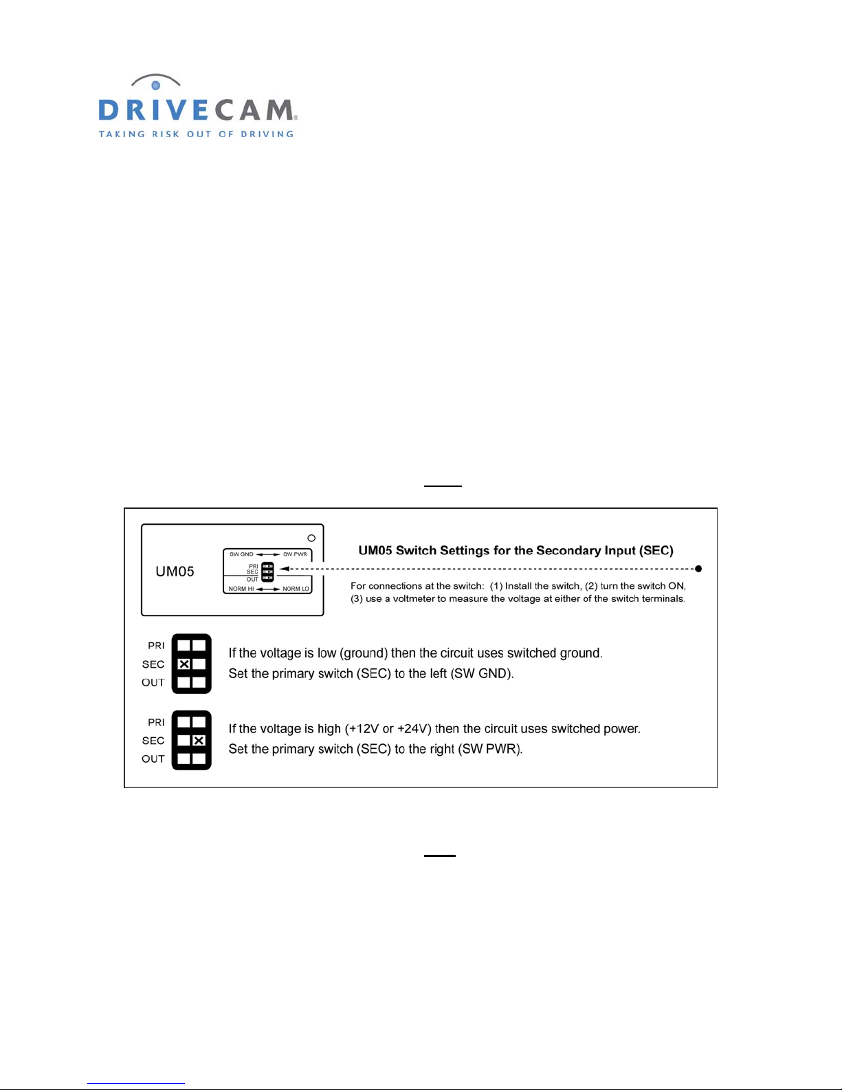
12. Connect the orange wire (secondary trigger input)
The secondary trigger input (ORANGE WIRE) can be connected to one of several different
electronic devices within the vehicle (e.g. taxi meter, car alarm, horn, button, etc.). The event
recorder will then record an event each time the device is activated. In most cases, it is connected to a
concealed switch that can be manually triggered by the driver in an emergency. Most standard constant
state switches (toggles, push on/push off) or momentary pushbuttons may be used.
Testing the Switch Circuit
Use the following steps to determine the type of switch circuit (switched ground or switched power) and
make the appropriate secondary (SEC) switch settings on the Universal Module (UM05).
Step 1 Install the switch then turn the switch “ON”.
Step 2 Use a voltmeter to measure the voltage at either
Step 3 Turn the switch “OFF”.
Step 4 Use a voltmeter to measure the voltage at each
of the switch terminals.
of the switch terminals.
One terminal will remain the same as measured in the previous step – the othe r terminal voltage
will have changed. The connection must be made to the terminal that changed voltage.
Step 5 Connect the orange wire to the switch.
Make sure you are connecting to the correct side of the switch circuit as measured in step 4.
DRC 242-A 2007-08-03 Page 13 DC3 with SEM Installation Instructions
Page 14
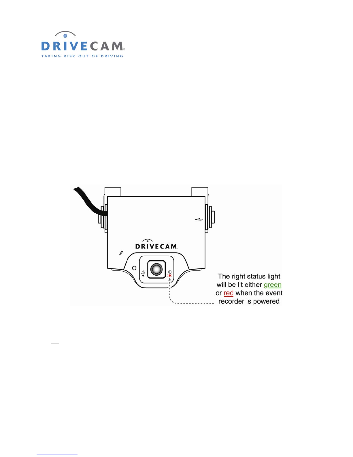
13. Test the red connection (continuous power)
Once power and ground connections are made, the LED status light to the right of the interior-facing lens
should be on (either a green or red light) when the vehicle’s engine is off and the key is removed from the
ignition.
Step 1 If the right LED is on, the event recorder is connected properly.
Step 2 If the right LED is not on, recheck the wiring connections and/or fuses.
* * * The right LED should remain on when the key is in any position * * *
The LED on the left of the lens will light (solid green) for about 30 seconds after power is first applied. If
the left
LED does not turn off or if it begins flashing (either red or green), please call DriveCam Technical
Support for instructions.
NOTE: See pages 26 & 27 for detailed descriptions of the LED behavior (light patterns).
DRC 242-A 2007-08-03 Page 14 DC3 with SEM Installation Instructions
Page 15
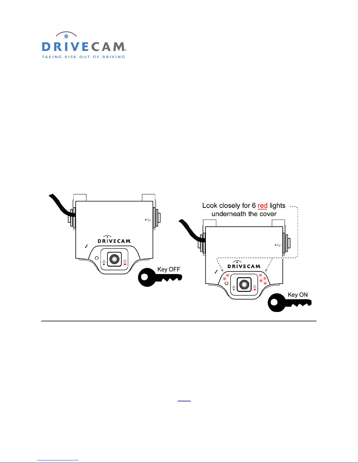
14. Test the brown connection (switched power)
Underneath the translucent cover surrounding the interior-facing lens are six small, infrared lights. These
lights can only be seen when they are lit, and they are only lit when power is being provided through the
brown wire (i.e. when the key is in the ignition (A) position).
NOTE: This is the event recorder’s IR Illuminator feature (see page 13 for information).
Step 1 Turn the key to the Ignition / Switched-On position.
Step 2 Look closely for the six red LEDs underneath the translucent cover.
Step 3 Turn the key to the OFF position. The six red LEDs should go out.
If the test worked as described, the brown wire has been connected properly. Continue to the next
section to test the primary trigger input.
If the test did not work as described, repeat the test in a darker area. The lights are difficult to see in
bright light. If still not lit, check with the key in a different position and then recheck the wiring.
* * * The six red lights must go out when the key is in the OFF position * * *
* * * The single (red or green) LED to the right
DRC 242-A 2007-08-03 Page 15 DC3 with SEM Installation Instructions
of the lens will always remain lit * * *
Page 16
15. Test the white connection (primary trigger input)
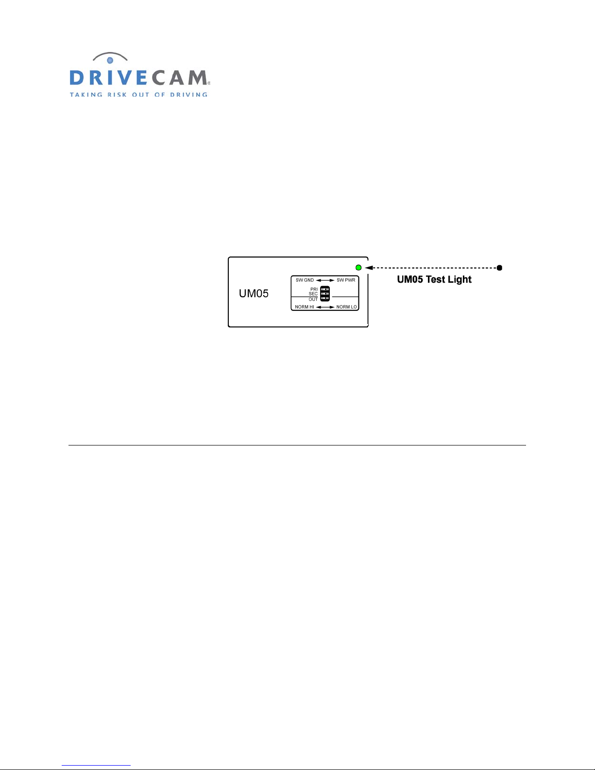
Place the UM05 in a location where you can see the UM05 Test Light. Verify that the event recorder is
powered (the right status light on the event recorder is either solid green or solid red).
NOTE: The status lights on the event recorder will not flash while recording events
through the primary or secondary trigger inputs (see page 25). Use the UM05 Test
Light to ve
Step 1 Open a vehicle door.
The UM05 Test Light should be lit (solid green).
rify proper wiring and switch configuration.
Step 2 Close all vehicle doors.
The UM05 Test Light should go out (at the same time as the dome light).
If the test worked as described, the primary trigger input is functioning correctly. Continue to the next
section to test the secondary trigger input.
If the UM05 Test Light was reversed (i.e. lit when the doors were closed and out when a door was
opened) then the primary (PRI) switch setting on the UM05 is incorrect. Change the switch setting (page
11) and repeat the test procedure.
If the UM05 Test Light is on all of the time then the con
as described on page 12.
If the UM05 Test Light did not light at all, check the power, ground, & primary wire connections. Make
sure the connection was made to the correct side of the circuit as described on page 12.
nection was made to the wrong side of the circuit
DRC 242-A 2007-08-03 Page 16 DC3 with SEM Installation Instructions
Page 17
16. Test the orange connection (secondary trigger input)
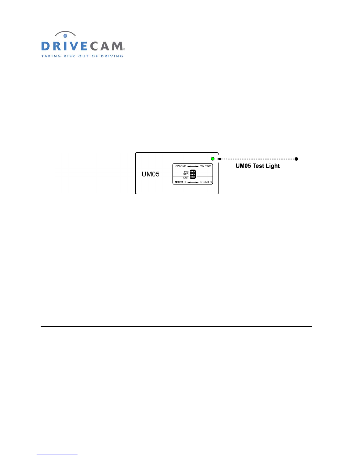
Place the UM05 in a location where you can see the UM05 Test Light. Verify that the event recorder is
powered (the right status light on the event recorder is either solid green or solid red).
NOTE: The status lights on the event recorder will not flash while recording events
through the primary or secondary trigger inputs (see page 25). Use the UM05 Test
Light to ve
Step 1 Close all of the vehicle doors and wait for the dome light to go out.
The UM05 Test Light should also go out.
rify proper wiring and switch configuration.
Step 2 Turn (or press) the secondary switch to “ON”.
The UM05 Test Light should light for approximately two seconds
NOTE: If you are using a momentary pushbutton (press ON – release OFF), press and
release the button. The UM05 Test Light should light for approximately two
seconds and then go out. Step 3 will not be necessary with this type of button.
Step 3 Turn (or press) the secondary switch to “OFF”.
There should be no indication from the UM05 Test Light.
If the test worked as described, the secondary trigger input is functioning correctly. Continue to the next
section to complete the installation.
If the UM05 Test Light did not light when the switch was turned “on” then the secondary (SEC) switch
setting on the UM05 is incorrect. Change the switch setting (page 13) and repeat the test procedure.
If the UM05 Test Light is
as described on page 13.
If the UM05 Test Light did not light at all, check the power, ground, secondary wire, & switch connections.
Make sure the connection was made to the correct side of the circuit as describ ed on page 13.
on all of the time then the con
nection was made to the wrong side of the circuit
and then go out.
DRC 242-A 2007-08-03 Page 17 DC3 with SEM Installation Instructions
Page 18

17. Finalizing Connections
This completes installation of the DriveCam Event Recorder and the primary and secondary triggers of
the UM05 device. If you are planning to use the output feature of the UM05, proceed to the next page to
continue with the installation.
If you are not planning to use the output feature of the UM05, cap the two output wires (blue and yellow
wires) on the UM05 switch cable. Coil all excess wiring and secure it with the UM05 in a safe location.
DRC 242-A 2007-08-03 Page 18 DC3 with SEM Installation Instructions
Page 19
18. Using the Output Feature (blue & yellow wires)
The DriveCam Event Recorder has the ability to control other devices within the vehicle. The event
recorder has an output signal that will change from its normal state whenever an event is triggered. After
saving that event, the output returns to its normal state.
With the UM05 device, this function is greatly enhanced. The user has the ability to determine the
voltage level of the output as well as whether the output’s normal state is high or low. The output can
provide TTL level logic signals, or it can be used to operate loads drawing up to 2 Amperes of current.
These loads can be either resistive (lights) or inductive (relays or motors).
Due to the wide variety of ways that this output may be used, it is impossible to cover all potential
applications. The instructions and examples contained here should be considered a general guide. Your
particular application will determine the actual wiring configuration.
NOTE: Due to the variety of ways the Output feature may be used it is recommended that
any wiring of this device be done by a qualified automotive electrician.
CAUTION: Although every effort has been made to prevent it, incorrect wiring of the
Output feature may cause damage to your UM05.
General Operation
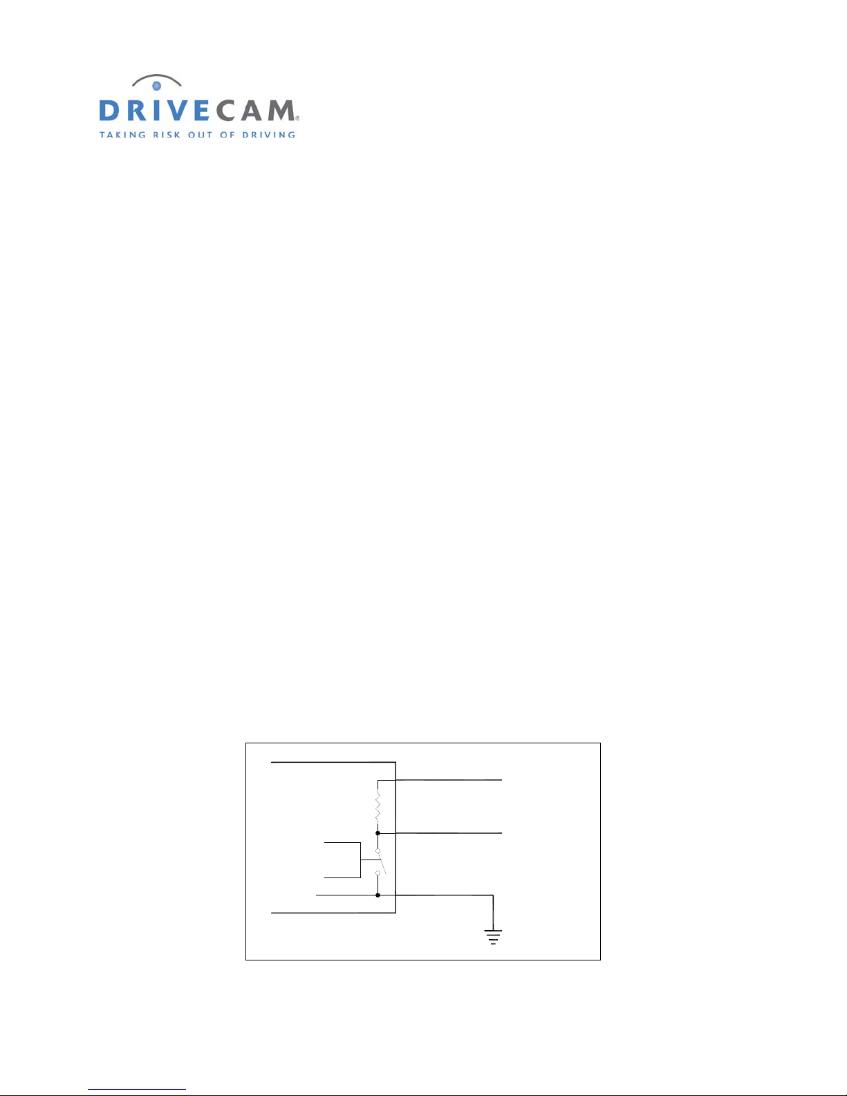
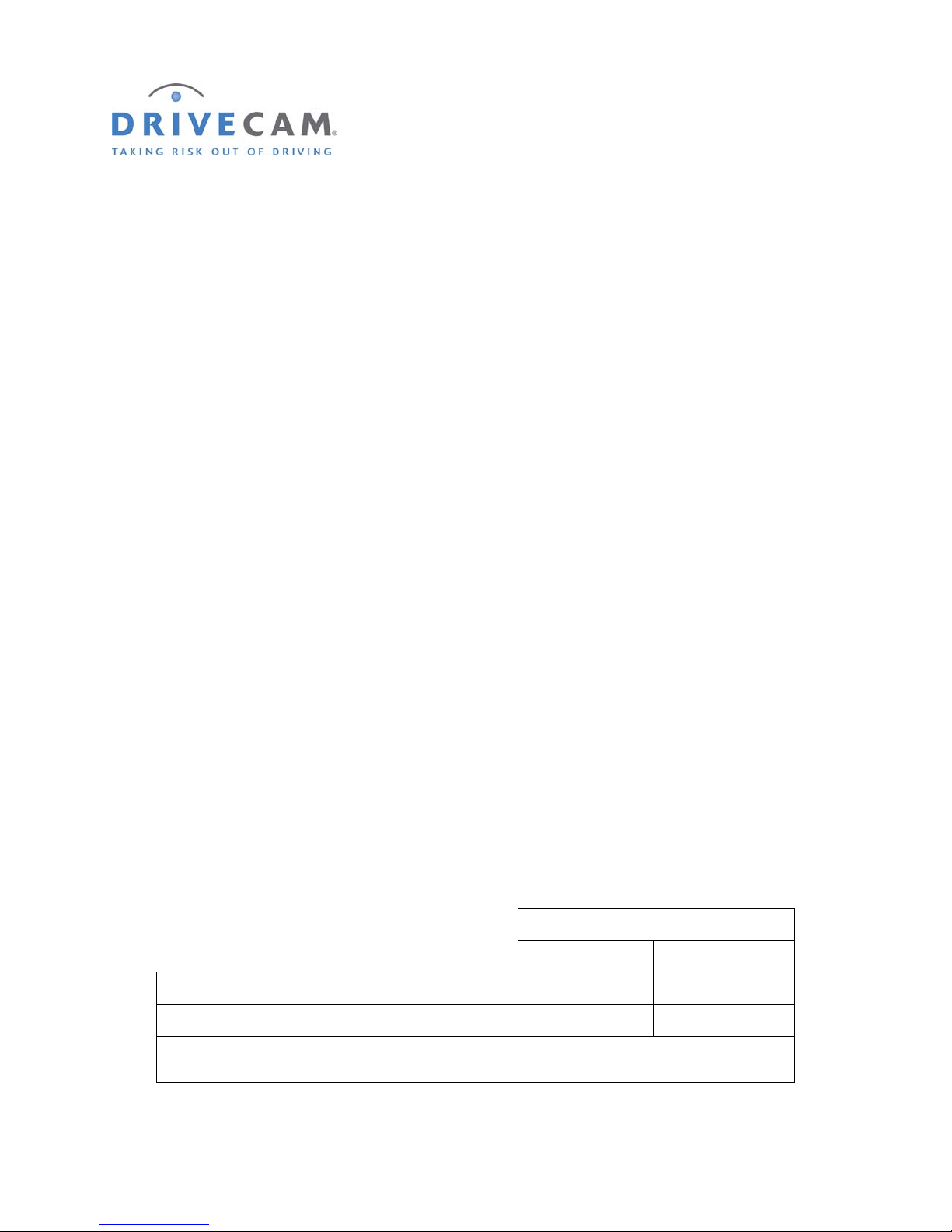
The Output feature of the UM05 acts like a switch. One side of this switch is permanently connected to
the black wire (ground) of the UM switch cable. The other side of the switch is connected to the blue
wire. Also connected to the blue wire is a 1,800 Ohm (1.8KΩ) resistor whose opposite side is connected
to the yellow wire. This yellow wire needs to be wired to a voltage source if you want the voltage at the
blue wire to go up when the switch is open. Figure 1 shows a blo c k diagram of the UM05 output circuit.
Yellow Wire
1,800 Ohms
1/2 Watt
Blue Wire
UM05
Control
Black Wire
(Always Connected to Ground)
Ground
DRC 242-A 2007-08-03 Page 19 DC3 with SEM Installation Instructions
IGURE 1 UM05 OUTPUT BLOCK DIAGRAM
F
Page 20
* * * These procedures apply only to DC3 Video Event Recorders * * *
If the OUT switch on the UM05 is set to NORM LO, the output switch will be open all the time unless an
event has been triggered in the DriveCam Event Recorder. When an event is triggered, the output switch
will close for about 1 second. When that is complete, the switch will open again. If the OUT switch is set
to NORM HI the switch will work in the opposite way (i.e. closed normally, open when an event is
triggered).
Wiring Options
There are many ways the output of the UM05 can be used. The following section shows some sample
applications. Your particular application will determine the actual wiring configuration. These examples
should only be considered a general guide.
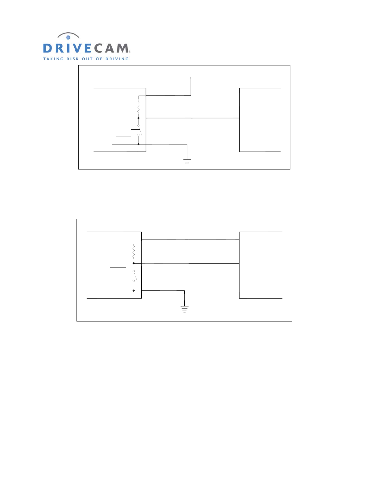
Example 1: Triggering a GPS or other electronic device
Generally, it is very easy to connect your UM05 to trigger a GPS or other electronic device. These types
of devices typically require voltage levels but very low current. The yellow wire is connected to +12V so
that the voltage at the blue wire will go up whenever the switch opens. When the switch is closed the
voltage at the blue wire will be low. The yellow wire can be tied to a constant or switched voltage source.
When tied to a constant voltage source there will be approximately 0.007A (7mA) of current drawn at all
times. If the yellow wire is tied to a switched voltage source, the voltage at the blue wire will never go up
when the switched voltage source (i.e. ignition switch) is off.
Table 1 shows the UM05’s approximate output level of the blue wire for an event recorder during an event
or during normal, non-event operation. If the GPS requires the voltage to go high to trigger it, set the
UM05’s OUT switch to NORM LO. If the GPS requires the voltage to go low to trigger, set the switch to
NORM HI. If the GPS setting is selectable a NORM LO setting should typically be used.
NOTE: With the yellow (sup ply) wire connected to a switched voltage source and the
UM05’s OUT switch set to NORM HI, the blue wire will go low whenever the voltage
is turned off even though there is no event.
UM05 Switch Setting
Norm Lo Norm Hi
DriveCam Event (DC3) High* 0V
No Event 0V High*
These settings apply only to DC3 Video Event Recorders
High = 12V – 24V
TABLE 1 VOLTAGE LEVEL AT THE BLUE WIRE
DRC 242-A 2007-08-03 Page 20 DC3 with SEM Installation Instructions
Page 21
+12V
Yellow Wire
1,800 Ohms
1/2 Watt
UM05
Control
Blue Wire
Black Wire
(Always Connected to Ground)
Ground
Input GPS
IGURE 2 UM05 TO 12V GPS INPUT
F
If the GPS or other device requires a voltage other than the normal vehicle voltage (i.e. a +5V level) and
that voltage is available at the GPS, simply connect the yellow wire to the voltage source.
UM05
1,800 Ohms
1/2 Watt
Control
Yellow Wire
Blue Wire
Black Wire
(Always Connected to Ground)
Ground
+5V
Input GPS
IGURE 3 GPS REQUIRING SPECIAL VOLTAGE
F
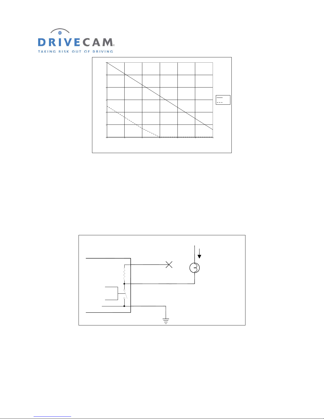
For applications like those shown in example 1, it is important to realize that the ability to supply current
from the blue (output) wire to a device is limited. How much current can be drawn from the wire is
dependent on the voltage necessary at the wire. Figure 4 shows the relationship of voltage at the blue
(output) wire vs. current being drawn for 12 Volts and 5 Volts at the yellow (supply) wire. Normally,
devices like GPS and other electronic devices with signal inputs require very little current so the voltage
supplied to them by the blue wire will be very close to the voltage supplied to the yellow wire.
DRC 242-A 2007-08-03 Page 21 DC3 with SEM Installation Instructions
Page 22
12
10
8
6
Voltage (V)
4
2
0
0123456
Current (mA)
12V
5V
IGURE 4 VOLTAGE VS. CURRENT AT THE BLUE WIRE
F
Example 2: Triggering devices that use up to 2 Amps and have a separate ground wire
There are many auxiliary devices for vehicles that fit into this category. Auxiliary lights, warning buzzers,
and relays are some of the possible devices. If the total current draw is less than 2 Amps and the device
has a separate ground wire (not chassis grounded) this method can be used. In this situation, the yellow
supply wire is not used. Instead the device to be operated has its positive wire connected to a +12 Volt
source and the negative wire is connected to the blue wire as shown in figure 5.
+12V
_
I < 2 Amps
Yellow Wire
(No Connection)
1,800 Ohms
1/2 Watt
Blue Wire
Lamp or other Load
UM05
Control
IGURE 5 EXAMPLE 2, LOAD WITH A SEPARATE GROUND
F
In example 2, because we are switching the ground wire, operation of the device may seem backwards.
To turn the device ON we need the UM05 switch to turn ON which will make the voltage at the blue wire
go LOW. Table 2 shows how to set the UM05 OUT switch to achieve the desired function at the load.
DRC 242-A 2007-08-03 Page 22 DC3 with SEM Installation Instructions
Black Wire
(Always Connected to Ground)
Ground
Page 23
UM05 Switch Setting
Norm Lo Norm Hi
DriveCam Event OFF ON
No Event ON OFF
TABLE 2 OPER ATING A LOAD FROM THE BLUE WIRE
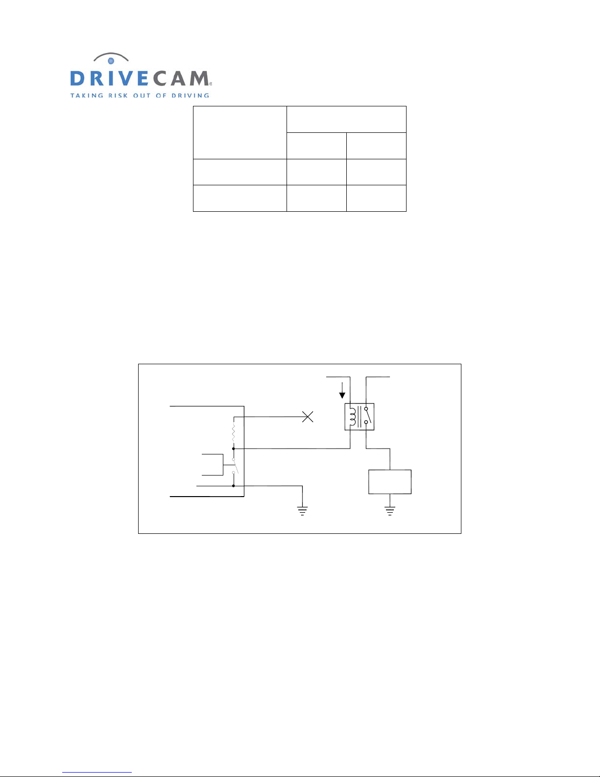
Example 3: Triggering heavy current or chassis ground devices
Example 3 is actually very much like example 2, but the load that is operated by the UM05 is a relay.
This configuration is used if the load current of the device is greater than 2 Amps, or if the device has a
chassis ground (no separate ground wire). The UM05 OUT switch settings for this example, a Normally
Open (NO) relay, are those shown in table 2. If a Normally closed (NC) relay were used the table would
be reversed.
1,800 Ohms
1/2 Watt
Yellow Wire
(No Connection)
Blue Wire
+12V
_
I < 2 Amps
+12V
Relay
UM05
Control
IGURE 6 HEAVY CURRENT OR CHASSIS GROUND DEVICES
F
Example 4: Triggering a GPS or other electronic device that needs more drive current
In some rare cases, the UM05 may be connected as shown in example 1, but there is not enough current
supplied by the UM05 to drive the input. The drive current may be increased by duplicating the job of the
UM05’s internal supply resistor with an external one (see figure 7). If this is done, three precautions must
be adhered to:
Black Wire
(Always Connected to Ground)
Ground
User
Load
First, the current through the resistor must be 2 Amps or less. For a 12 Volt electrical system this means
the resistor should be greater than 8 Ohms. To prevent other problems, the resistor value should be as
high as possible and still pass the current needed for the application.
DRC 242-A 2007-08-03 Page 23 DC3 with SEM Installation Instructions
Page 24
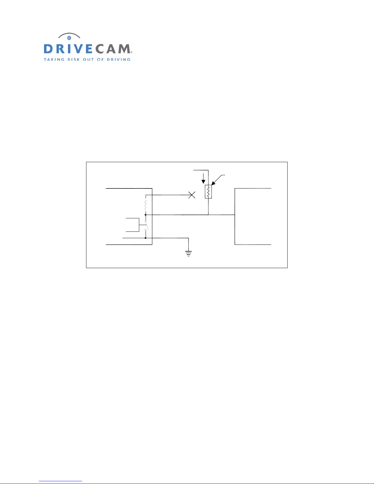
Second, the resistor will have to be able to handle the wattage dissipated by being connected to ground.
For that 8 Ohm resistor on a 12 Volt system the wattage rating of the resistor should be above 30 Watts.
Third, the current in this example could be high enough to cause a serious drain on the vehicle battery.
The 12V to the external resistor should be switched off with the ignition switch, or the blue line should not
be configured so that it is normally low when the ignition switch is off.
NOTE: Anyone attempting a type of installa tion like example 4 should have a thorough
understanding of electrical systems and electricity. Incorrect implementation of
this could damage the UM05 and/or create a fire hazard for the vehicle.
UM05
1,800 Ohms
1/2 Watt
Control
+12V
_
I < 2 Amps
Yellow Wire
(No Connection)
Blue Wire
Black Wire
(Always Connected to Ground)
Ground
External Resistor
At Least 8 Ohms (12V)
Input GPS
IGURE 7 PROVIDING EXTRA DRIVE CURRENT
F
DRC 242-A 2007-08-03 Page 24 DC3 with SEM Installation Instructions
Page 25

Frequently Asked Questions
How does the event recorder work?
The DriveCam Event Recorder is mounted on the windshield behind the rearview mirror and captures sights and sounds inside and outside the vehicle.
The forward facing lens (outside view) captures the viewing area in the front of the vehicle. The inside lens captures what is happening inside the
vehicle plus whatever is visible through the side and rear windows. All audio that can be heard within the vehicle is also recorded. The device is
constantly recording in a digital loop. When triggered, it immediately saves the 10 seconds before the trigger and continues to record and save the 10
seconds following the trigger. Event recordings are triggered by unusual motion, such as hard braking, swerving, or collision. They can also be
triggered manually by pressing the button on the event recorder.
Why are there two different power connections?
There are two different mechanisms at work in the event recorder, each is described in detail below. The first is the event recorder itself, capturing
audio and video when triggered. This should always be on to capture events even when the vehicle is parked and switched off. The second is the
event recorder’s IR Illuminator feature, which lights the interior of the vehicle with infrared light to enhance recordings in low light situations. This draws
additional power and should not be connected (brown wire) to a continuous power source.
The red wire connects to a power source that is always on, even when the key is off. The brown wire connects to a power source that is only on when
the key is in the ignition position (and when the vehicle is running), but not when the key is off.
Why must the event recorder be connected to a continuous power source?
The event recorder is designed to remain on 24 hours a day, 7 days a week. This allows the device to record events even when the vehicle is parked
(hit and run accidents, vandalism, theft, etc.) and when the vehicle loses ignition-switched power for any reason. Unlike the event recorder’s built-in IR
Illuminator (which must be connected to an ignition-switched power source), the event recorder itself draws minimal power from the vehicle and is less
likely to drain the battery.
What is the event recorder’s IR Illum inator feature?
The Infrared (IR) Illuminator lights the interior of the vehicle with infrared light (invisible to the eye). This enables the event recorder to record clearly lit
images in low light situations. The Illuminator draws additional power from the vehicle, which is why it is only switched on when the key is turned to the
ignition position and when the vehicle is running. The brown wire on the power cable provides this switch, sensing when to turn the Illuminator on and
off. Infrared light from the Illuminator shines out through the thin translucent cover surrounding the interior-facing lens. By looking closely through this
translucent cover, you can see the six red lights (dimly lit LEDs) underneath that indicate when the Illuminator is switched on.
Why do the status lights not flash while recording events through the primary and secondary trigger inputs?
This is a security feature referred to as “stealth mode”. It enables the driver to silently trigger an event recording in a way that does not provide any
visual or audible clues that a recording is being made.
How do I remove or reinstall the mounting bracket?
The mounting bracket is not easy to remove once it has been stuck to the window so that tampering is minimized. Do not try to pull or pry the bracket
off – it will destroy the bracket and may break the window. Use a thin putty knife and lubricant to cut through the adhesive. First, remove the event
recorder from the bracket. Then apply a small amount of lubricant to the putty knife and slide the blade between the bracket and the window. Gently
rock the blade back and forth while pushing forward until the bracket is completely removed. You will then need a new mounting bracket from
DriveCam.
Who do I contact for more information or technical assistance?
We are here to help. DriveCam Technical Support is available 24 hours / 7 days at (866) 910-0403. For
international assistance please call (858) 380-3007.
DRC 242-A 2007-08-03 Page 25 DC3 with SEM Installation Instructions
Page 26
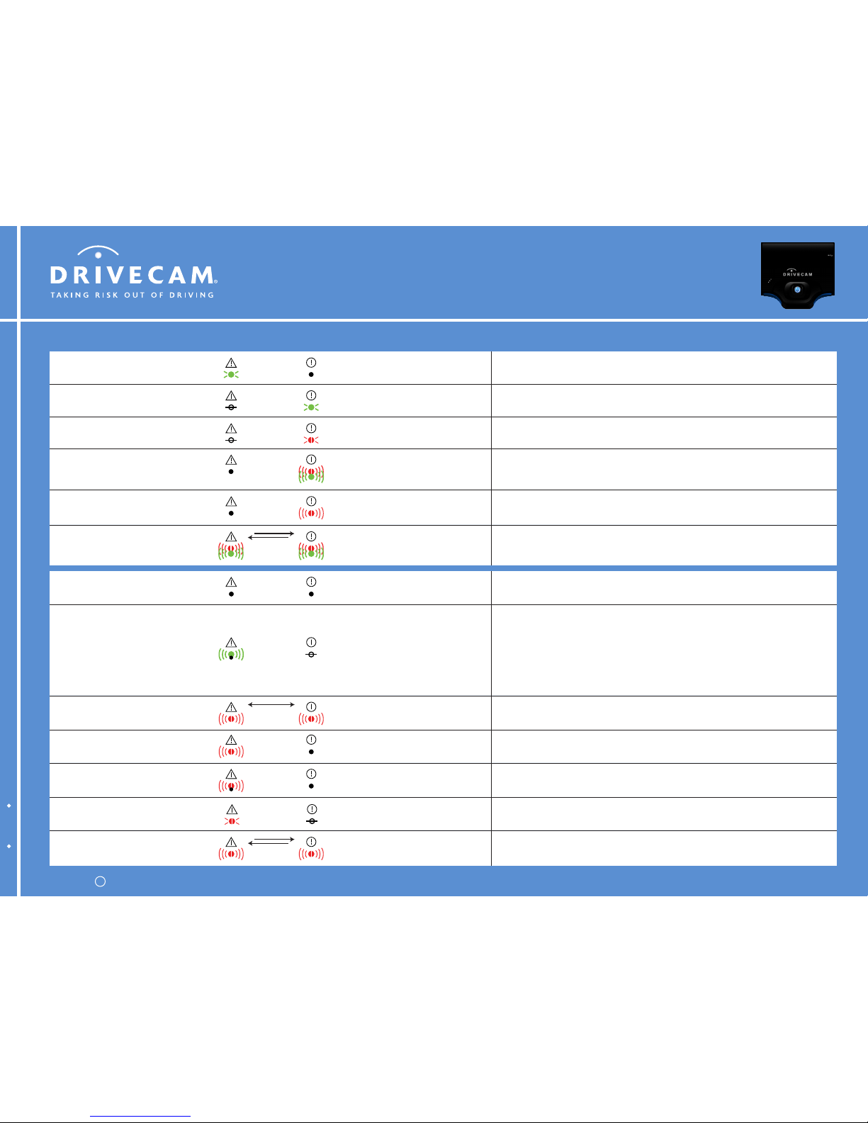
Boot error (fast blink) or event recorder is in limited mode (slow blink).
Contact DriveCam Technical Support.
Both LEDs blinking
red together
Both LEDs blinking
red together
No event files are stored in memory.
The event recorder is ready to record an event.
Solid greenAny state
The event recorder is powering up (booting).
The warning light should go off within 30 seconds. If not, cycle power.
OffSolid green
Power to the event recorder is off or less than 9V. Supply power to the
event recorder. Check vehicle battery and wiring to restore voltage.
OffOff
Unsuccessful wireless connection.
2 blinks = No WAP found or failed to connect with WAP (WiFi)
Failed to make cell-modem data connection (Cellular)
3 blinks = Connected to WAP but no DHCP address (WiFi only)
4 blinks = Received DHCP but no TCP connection with HindSight (WiFi)
Data connection but no TCP connection with HindSight (Cellular)
5 blinks = HindSight protocol error (WiFi & Cellular)
Any stateBlinking green then off
Event files are stored in memory and ready to download.
The event recorder is ready to record an event.
Solid redAny state
An event was triggered and is being recorded.
Alternating green & redAny state (off is typical)
Data transfer is in progress. Event files are being downloaded. The rate of
flashing indicates the speed of the connection.
Blinking redAny state (off is typical)
Internal error.
Contact DriveCam Technical Support.
Both LEDs blinking
red alternating
Both LEDs blinking
red alternating
Backup battery failure.
Contact DriveCam Technical Support.
Any stateSolid red
Nonvolatile memory failure.
Contact DriveCam Technical Support.
Off
Blinking red
then off repeatedly
Memory failure.
Contact DriveCam Technical Support.
OffBlinking red continuously
Alternating green & redAlternating green & red
Firmware upgrade is in progress. The event recorder is operating normally
but is not available to record an event.
Normal OperationWarnings & Errors
DriveCam Technical Support is available 24 hours / 7 days at (866) 910-0403.
Warning (Left LED) Status (Right LED) Description
Copyright 2007 DriveCam, Inc. All rights reserved.c
DRC 971-A May 2007 Commercial Wi-Fi & Cellular
DC3 Video Event Recorder LED Behavior
for Wi-Fi & Cellular DC3 models
Page 27
DriveCam Technical Support is available 24 hours / 7 days at (866) 910-0403.Copyright 2007 DriveCam Inc. All rights reserved.c
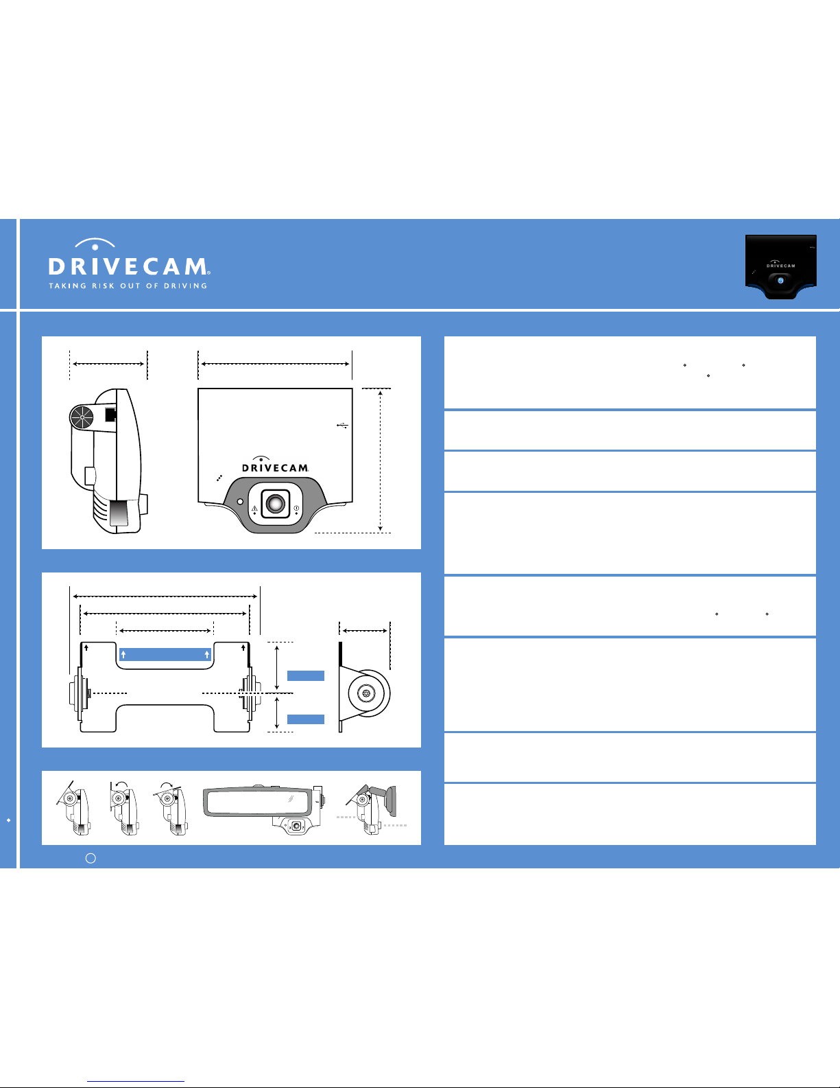
DC3 Video Event Recorder Specifications
4.6 in. (11.7 cm)2.1 in. (5.3 cm)
DRC 974-A August 2007
4.3 in. (10.9 cm)
2 11/16 in. (6.8 cm)
5 1/4 in. (13.3 cm)
4 11/16 in. (11.9 cm)
1 7/16 in. (3.7 cm)
1 1/16 in. (2.7 cm)
2 3/8 in. (6.8 cm)
Short Arm
Long Arm
Centerline of Torx Screw
This end up on windshield
Standard Windshield Mounting Bracket
Download Times (operating environment will affect performance)
Download a 20 second event via USB:
Download a 20 second event via Wi-Fi:
Download a 20 second event via Cellular:
5 seconds
10 seconds
2 minutes
Physical Security
Security screws used to seal unit:
Block to prevent power disconnection:
Memory format:
Mounting bracket:
Full coverage
Yes
Disk on chip (non-removable)
Non-removable
Environmental
Dimensions (excludes mounting bracket):
Operating temperature:
Weight:
4.6 x 4.3 x 2.1 in. (W/H/D)
11.7 x 10.9 x 5.3 cm (W/H/D)
-40 to 185 F (-40 to 85 C)
8.3 oz. (236 g)
Event Characteristics
Typical 20 second event file size:
Average:
Minimum:
Maximum:
Standard resolution:
Ability to capture multiple triggers:
Advanced triggering algorithms:
2MB
0.5 - 1MB
3 - 4MB
640 x 368 (235,520 pixels)
Yes (up to 60 seconds record time)
Yes (reduces false positives)
Advanced Functionality (may require additional peripherals)
Speed, heading and location through GPS:
Speed and vehicle idling through OBD:
Driver identification support through RFID card:
Safety Enhancement Module (SEM) support:
Infrared illuminator for low light conditions:
Input/output connectors for additional functionality:
Yes
Yes
Yes
Yes (integrated)
Yes
Yes
Connectivity
Wireless (two models available):
USB (both models):
Cellular (CDMA) or Wi-Fi (802.11b)
USB 2.0 (USB Mini A or Mini B plug)
Power
Standard input voltage:
Power input connector to event recorder:
12V or 24V (9V min. to 30V max.)
RJ45 (short body)
General
Memory available for event and data storage:
Horizontal field of view:
Articulating interior lens:
Accelerometers:
Manual trigger:
96MB
92 (internal) / 75 (external)
+/- 13.5 (horizontal or vertical)
3 axis (forward, lateral & vertical)
Yes
 Loading...