

DRITEL 3G-S7-LS-12A10W-FS Installation Manual
Dritel
3G Series 7
Loud Speaking Telephone
Installation Manual
3G-S7-LS-12A10W-FS
Manufactured with pride by
KJ Precision Engineering PTY LTD
Brisbane Australia.
Serial Number; 3G-S7-LS-_________
Manual Version 2/2013
1

Intentionally left Blank
Manual Version 2/2013
2
Introduction 3
Features and Applications 4
Specifications and Dimensions 5
Installation 7 7
Tools required 7
Start up 18
Closing the Phone 20
Mother Board 21
Trouble Shooting 22
Parts List 23
Modifications List 24
User Notes 25
Warranty 26
Manual Version 2/2013
3

INTRODUCTION
Thank you for selecting the Dritel Series 7 3G Solar Powered Telephone. Each unit is thoroughly tested and
inspected at our factory before delivery. We take particular pride in producing one of the finest quality products
available today. Please take a few minutes to familiarize yourself with this step by step manual before
commissioning the unit.
This phone is designed to meet all relevant specifications set out for safe and correct operation regarding its
application. We strongly advise against modifying or changing the method of installation as this may render the
phone unsuitable for its application. Incorrect installation procedure may render the warranty null and void.
Dritel believes service and backup of our products is paramount. Any questions or problems not covered in the
manual can be referred directly to the manufacturer, or to your local distributor for a quick resolution.
Please use the following contacts for assistance:
Manufacturer
KJ Precision Engineering, 16/388 Newman Rd Geebung, Brisbane, Australia, 4034,
Tel: +61 (7) 3265 3240 Email sales@kjeng.com.au
for technical information regarding phones
info@kjeng.com.au for general inquiries
Manual Version 2/2013
4

FEATURES
Australian designed and manufactured
Designed to maximize vandal resistance and weather proof characteristics
Automatic time out or hang-up when the call is terminated
Self diagnostics and automatic reporting
Manufactured from Marine grade stainless and Marine grade aluminium
UV rated powder coating
Modular construction
One person installation and ease of servicing
Can be customized to suit the customer’s requirements
APPLICATIONS
Roadside Help Phones
Railways (Signal Post and Siding Telephones)
Public area security, parking lots, malls, sporting events, beaches
Parklands and recreation areas including national parks, trails, walks, and forestry’s.
Remote situations
Airports
National Parks
Universities
Mining
Manual Version 2/2013
5

SPECIFICATIONS
Technical Specifications
Working Frequency Range – WCDMA850/1900/2100MHz GSM850/900/1800/1900MHz
Operating voltage – 7.4V-12V
Idle current - 75mA off hook current - 160mA
Each unit can be simply reprogrammed from any location. The Unit will send a confirmation “SMS” to the
sender showing the new numbers programmed.
Automatic Diagnostic reporting
The Unit will automatically send a message when one or more of the following conditions occur.
1). Battery state below 9V
2). Faulty switch or keypad
3). Led indicator condition
Manual Fault diagnosis
Upon requesting a Fault Diagnosis from the phone, the following information will be sent in the form of an
SMS”
1). Signal status
2). Battery status
4). Keypad/Switch status
5). Indicator light condition
6). Preprogrammed Call number
7). Preprogrammed SMS reporting number
Power Specifications
10W Solar panel
Battery – SLA 12V, 12A battery
6
Manual Version 2/2013

Engineering Specifications
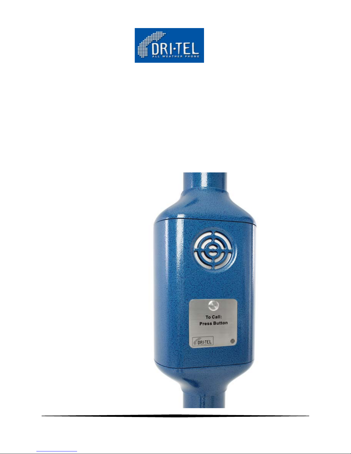
Casing material – Marine grade extruded aluminium, Marine grade die cast aluminium, 316 stainless steel.
Finish – UV rated powder coat, standard colour blue
Fittings – Minimum 316 grade stainless steel
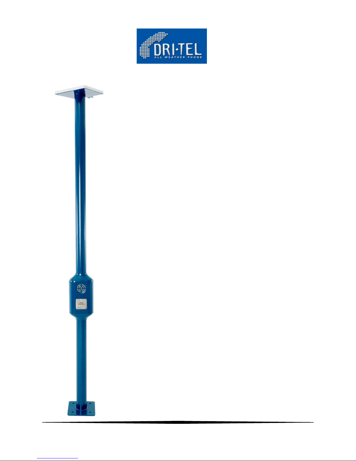
Standard overall height – 3m (Height optional)
Weight -20 kg (Including 12 Ah battery)
Phone Case outside dimensions – 460mm high x 230mm wide x 160mm deep
Pole diameter- 100mm
Built in three sections - Lower Pole, Phone Unit, and Upper Pole
IP 55 Rating
Options
User location lighting
CCTV Monitoring and recording
Mast height to customer specifications
Increased solar panel capacity and battery capacity or remote 12V power source
Range of colours
Hotline (Single call) or Automatic (Keypad)
Ground, wall, barrier or custom mounting
Customized construction
Security screws
Manual Version 2/2013
7

INSTALLATION
Careful consideration of the positioning for each unit must be made before installation. User safety
should be maximized along with ease of access to the phone. The solar panel should be adjusted to achieve
maximum charge. In general terms, face the solar panel to the North in the Southern Hemisphere and South in the
Northern Hemisphere. There should not be any shadows cast upon the panel throughout the middle 5 hours of
daylight.
All dimensions shown in the Installation Drawings are in millimeters
Tools required
Multi Meter
Spirit Level
10mm Spanner
19mm Spanner
21mm Spanner
5mm Allen Key
6mm Allen Key
Cleaning rag
Manual Version 2/2013
8
 Loading...