

Page 1
READ AND SAVE THESE INSTRUCTIONS
XTR MODULATING SERIES
Electrode Steam Humidifier
Installation, Operation,
and Maintenance Manual
Page 2
Warnings and cautions
WARNINGS AND CAUTIONS
WARNING
Indicates a hazardous situation that could result in death or
serious personal injury if instructions are not followed.
mc_051508_1145
WARNING
Attention installer
Read this manual before installing, and leave this manual with product owner. This product must be installed by qualifi ed
HVAC and electrical contractors. Installation must be code approved. Improper installation can cause property damage,
severe personal injury, or death as a result of electric shock, burns, or fi re.
DriSteem
Europe: +3211823595
Read all warnings and instructions
Read this manual before performing service or maintenance procedures on any part of the system. Failure to follow all
warnings and instructions could produce the hazardous situations described, resulting in property damage, personal injury,
or death.
Failure to follow the instructions in this manual can cause moisture to accumulate, which can cause bacteria and mold
growth or dripping water into building spaces. Dripping water can cause property damage; bacteria and mold growth can
cause illness.
mc_032612_1153
®
Technical Support: North America: 800-328-4447
CAUTION
Indicates a hazardous situation that could result in damage to or
destruction of property if instructions are not followed.
Hot surfaces and hot water
This steam humidifi cation system has extremely hot surfaces. Water in steam cylinders, steam tubing, and dispersion
assemblies can be as hot as 212 °F (100 °C). Discharged steam is not visible. Contact with hot surfaces, discharged hot
water, or air into which steam has been discharged can cause severe personal injury. To avoid severe burns, follow the
cool-down procedure in this manual before performing service or maintenance procedures on any part of the system.
mc_032612_1154
Disconnect electrical power
Disconnect electrical power before installing supply wiring or performing service or maintenance procedures on any part of
the humidifi cation system. Failure to disconnect electrical power could result in fi re, electrical shock, and other hazardous
conditions. These hazardous conditions could cause property damage, personal injury, or death.
Contact with energized circuits can cause property damage, severe personal injury, or death as a result of electrical shock
or fi re. Do not remove cabinet covers until electrical power is disconnected.
Follow the shutdown procedure on Page 38 before performing service or maintenance procedures on any part of the
system.
mc_032612_1155
XTR INSTALLATION, OPERATION, AND MAINTENANCE MANUAL
ii
Page 3

Warnings and cautions
WARNING
Electrical shock hazard
If the humidifi er starts up responding to a call for humidity during maintenance, severe personal injury or death from
electrical shock could occur. To prevent such start-up, follow the shutdown procedure on Page 38.
mc_032612_1156
CAUTION
Follow steam piping recommendations
Controlling condensate fl ow and collection in an electrode steam humidifi er system is critical to maximum performance. Failure to
follow the steam piping recommendations in this manual can cause system pressure fl uctuations and increase cylinder pressure,
steam velocity, and condensate noise.
Hot discharge water
Discharge water can be as hot as 212 °F (100 °C) and can damage some drain plumbing materials not rated for hot drain
water. To prevent such damage, make sure drain water tempering is selected, and supply water is not heated. Do not shut off
supply water to the cylinder before it is drained.
Excessive supply water pressure
Supply water pressure greater than 80 psi (550 kPa) can cause the humidifi er to overfl ow.
mc_123010_1520-XT
XTR INSTALLATION, OPERATION, AND MAINTENANCE MANUAL
iii
Page 4

XTR INSTALLATION, OPERATION, AND MAINTENANCE MANUAL
iv
Page 5

Table of contents
WARNINGS AND CAUTIONS . . . . . . . . . . . . . . . . . . . . . . . . . . . . . . . . . . . . . . . . . . . . . . . . . . .
OVERVIEW. . . . . . . . . . . . . . . . . . . . . . . . . . . . . . . . . . . . . . . . . . . . . . . . . . . . . . . . . . . . . . . . .2
Product overview . . . . . . . . . . . . . . . . . . . . . . . . . . . . . . . . . . . . . . . . . 2
SPECIFICATIONS. . . . . . . . . . . . . . . . . . . . . . . . . . . . . . . . . . . . . . . . . . . . . . . . . . . . . . . . . . . . .4
Dimensional drawing . . . . . . . . . . . . . . . . . . . . . . . . . . . . . . . . . . . . . . 4
Voltages, weights, and dimensions . . . . . . . . . . . . . . . . . . . . . . . . . . . . 5
INSTALLATION . . . . . . . . . . . . . . . . . . . . . . . . . . . . . . . . . . . . . . . . . . . . . . . . . . . . . . . . . . . . . .6
Dispersion options . . . . . . . . . . . . . . . . . . . . . . . . . . . . . . . . . . . . . . . 6
Selecting a location . . . . . . . . . . . . . . . . . . . . . . . . . . . . . . . . . . . . . . 7
Humidifier . . . . . . . . . . . . . . . . . . . . . . . . . . . . . . . . . . . . . . . . . . . 7
Control and dispersion devices . . . . . . . . . . . . . . . . . . . . . . . . . . . . 7
Mounting . . . . . . . . . . . . . . . . . . . . . . . . . . . . . . . . . . . . . . . . . . . . . . 8
Removing covers and steam cylinder . . . . . . . . . . . . . . . . . . . . . . . . 8
Wall mounting humidifier . . . . . . . . . . . . . . . . . . . . . . . . . . . . . . . . 8
Installing steam cylinder . . . . . . . . . . . . . . . . . . . . . . . . . . . . . . . . . 8
Piping: . . . . . . . . . . . . . . . . . . . . . . . . . . . . . . . . . . . . . . . . . . . . . . . 9
Supply water and drain . . . . . . . . . . . . . . . . . . . . . . . . . . . . . . . . . 9
Field piping overview. . . . . . . . . . . . . . . . . . . . . . . . . . . . . . . . . . 10
XTR steam blower and XTR fan pack . . . . . . . . . . . . . . . . . . . . . . . 11
Field wiring . . . . . . . . . . . . . . . . . . . . . . . . . . . . . . . . . . . . . . . . . . . 12
Sensor placement . . . . . . . . . . . . . . . . . . . . . . . . . . . . . . . . . . . . . . . 18
Dispersion: . . . . . . . . . . . . . . . . . . . . . . . . . . . . . . . . . . . . . . . . . . . . 20
Selecting the location . . . . . . . . . . . . . . . . . . . . . . . . . . . . . . . . . . 20
Interconnecting piping requirements . . . . . . . . . . . . . . . . . . . . . . . . 21
XTR dispersion tube . . . . . . . . . . . . . . . . . . . . . . . . . . . . . . . . . . . 22
XTR steam blower . . . . . . . . . . . . . . . . . . . . . . . . . . . . . . . . . . . . 24
XTR fan pack . . . . . . . . . . . . . . . . . . . . . . . . . . . . . . . . . . . . . . . . 27
Download DriSteem literature
ii
DriSteem product manuals can be downloaded,
printed, and ordered from our website:
www.dristeem.com
DriSteem Technical Support
800-328-4447
OPERATION . . . . . . . . . . . . . . . . . . . . . . . . . . . . . . . . . . . . . . . . . . . . . . . . . . . . . . . . . . . . . . 32
Principle of operation . . . . . . . . . . . . . . . . . . . . . . . . . . . . . . . . . . . . 32
Control panel . . . . . . . . . . . . . . . . . . . . . . . . . . . . . . . . . . . . . . . . . . 34
Start-up . . . . . . . . . . . . . . . . . . . . . . . . . . . . . . . . . . . . . . . . . . . . . . 36
MAINTENANCE . . . . . . . . . . . . . . . . . . . . . . . . . . . . . . . . . . . . . . . . . . . . . . . . . . . . . . . . . . . 38
Steam cylinder . . . . . . . . . . . . . . . . . . . . . . . . . . . . . . . . . . . . . . . . . 38
Drain valve . . . . . . . . . . . . . . . . . . . . . . . . . . . . . . . . . . . . . . . . . . . . 39
Troubleshooting . . . . . . . . . . . . . . . . . . . . . . . . . . . . . . . . . . . . . . . . 40
Replacement parts: . . . . . . . . . . . . . . . . . . . . . . . . . . . . . . . . . . . . . . 45
Dispersion devices . . . . . . . . . . . . . . . . . . . . . . . . . . . . . . . . . . . . 45
XTR humidifier . . . . . . . . . . . . . . . . . . . . . . . . . . . . . . . . . . . . . . . 46
WARRANTY . . . . . . . . . . . . . . . . . . . . . . . . . . . . . . . . . . . . . . . . . . . . . . . . . . . . . . . . . . . . . . 48
XTR INSTALLATION, OPERATION, AND MAINTENANCE MANUAL
1
Page 6
OVERVIEW
Product overview
HUMIDIFIER
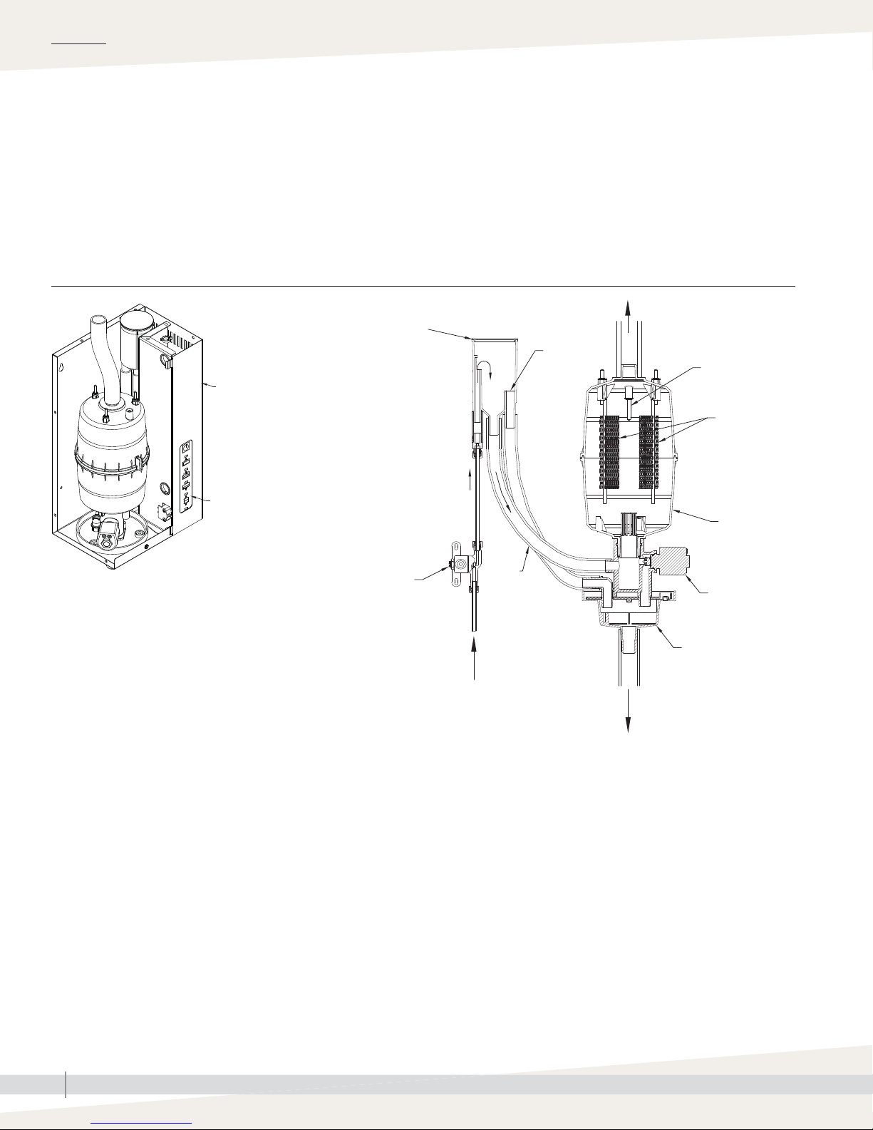
DriSteem XTR electrode steam humidifi ers use heat caused by electrical
resistance in their fi ll water to boil the fi ll water into humidifi cation steam.
Steam output and water conductivity are managed via automatic draining and
fi lling. See Figure 2-1.
FIGURE 2-1: XTR HUMIDIFIER COMPONENTS
Fill cup
Steam outlet
OM-7717
Painted cabinet and
removable covers
Control panel
Fill valve
Supply water
Fill
line
Overfl ow
High water sensor
Electrodes
Steam cylinder
Drain valve
Drain cup
90-1522a
Drain
XTR INSTALLATION, OPERATION, AND MAINTENANCE MANUAL
2
Page 7

Product overview
OVERVIEW
SUPPLY WATER
There are benefi ts and trade-offs to consider when the application allows a
choice between hard and softened water:
Hard water: The benefi t of hard water is less frequent draining and fi lling
than with soft water, which results in better energy and water effi ciency
and more consistent steam output. However, cylinder replacement could
be more frequent with hard water, because hard water scale coats the
electrodes. The harder the water, the more frequent the need for a new
cylinder.
Softened water: The benefi t of softened water is longer cylinder life
(depending on water chemistry) than with hard water, because softened
water does not coat the electrodes as much as hard water. However,
softened water ions stay in solution to much higher concentrations than hard
water ions. This requires more frequent draining and fi lling, which results in
less energy and water effi ciency and less consistent steam output.
CONTROL PANEL
The XTR humidifi er controller provides push-button operation and indicator
lights for operating status and troubleshooting information. See “Operation”
beginning on Page 32 for details.
Important:
• Recommended supply water conductivity
for DriSteem electrode humidifiers is 125
to 1250 μS/cm (roughly comparable to
water hardness of 3 to 36 grains per
gallon).
• Demineralized, deionized, and reverseosmosis water cannot be used. These
water types are not conductive enough
for electrode humidifiers.
FIGURE 3-1:
XTR HUMIDIFIER CONTROL PANEL
On-off button
Fill
Steam
Drain
Service
Indicator lights
XTR INSTALLATION, OPERATION, AND MAINTENANCE MANUAL
3
Page 8
SPECIFICATIONS
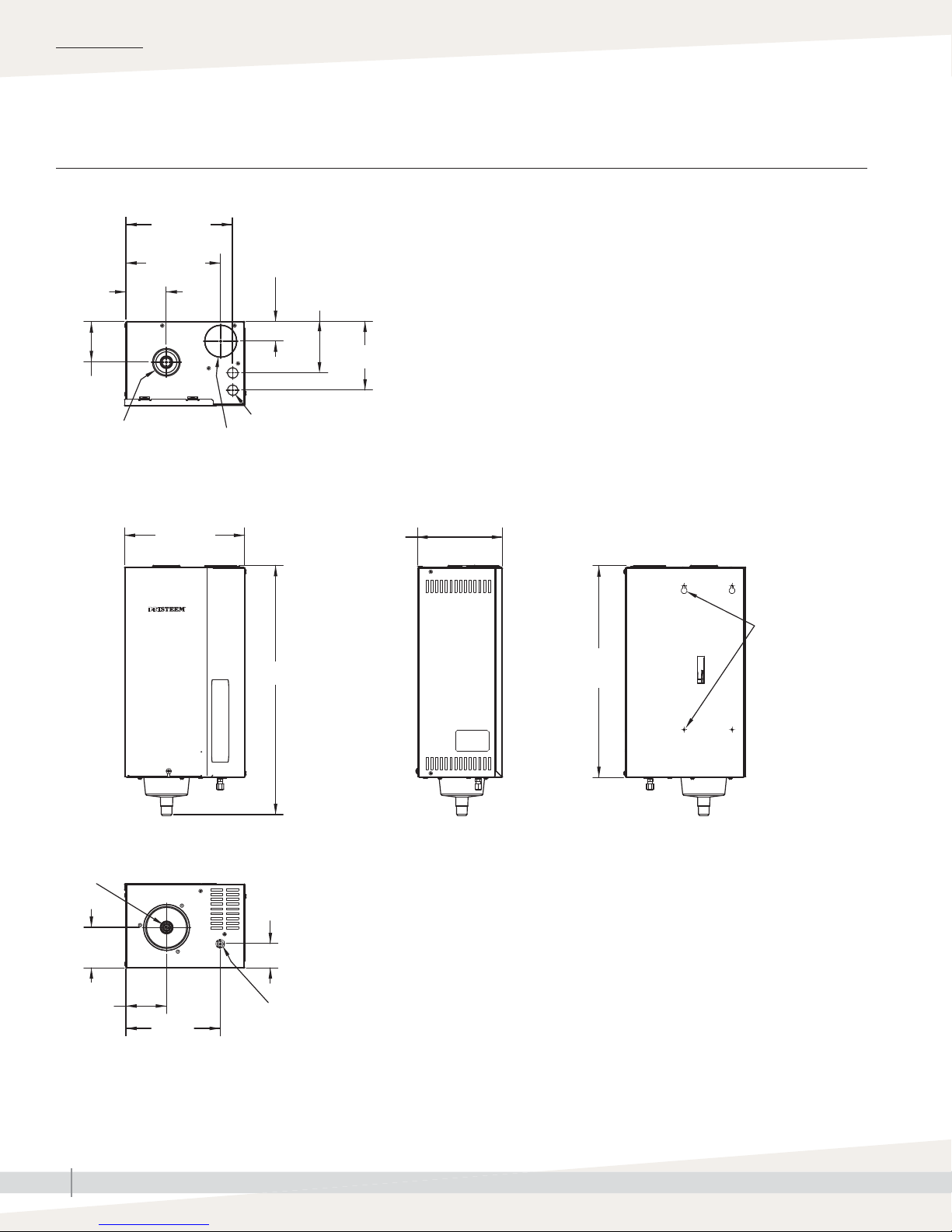
Dimensional drawing
FIGURE 4-1: XTR HUMIDIFIER DIMENSIONS
Top
8-7/8"
(225 mm)
3-3/8"
(86 mm)
3-3/8"
(86 mm)
Steam outlet
7-7/8"
(200 mm)
Fill cup
1-5/8" (41 mm)
4-1/4" (108 mm)
Electrical knockouts
5-3/4"(146 mm)
Drain
3-3/8"
(86 mm)
Front Side Back
10-1/8"
(257 mm)
20-7/8" (530 mm)
7-1/8"
(181 mm)
17-1/2"
(445 mm)
Bottom
2" (51 mm)
Mounting holes
(see mounting
dimensions in
Figure 8-1)
3-3/8"
(86 mm)
90-1701X
mc_050712_1400
XTR INSTALLATION, OPERATION, AND MAINTENANCE MANUAL
4
7-7/8"
(200 mm)
Supply water
connection
Page 9
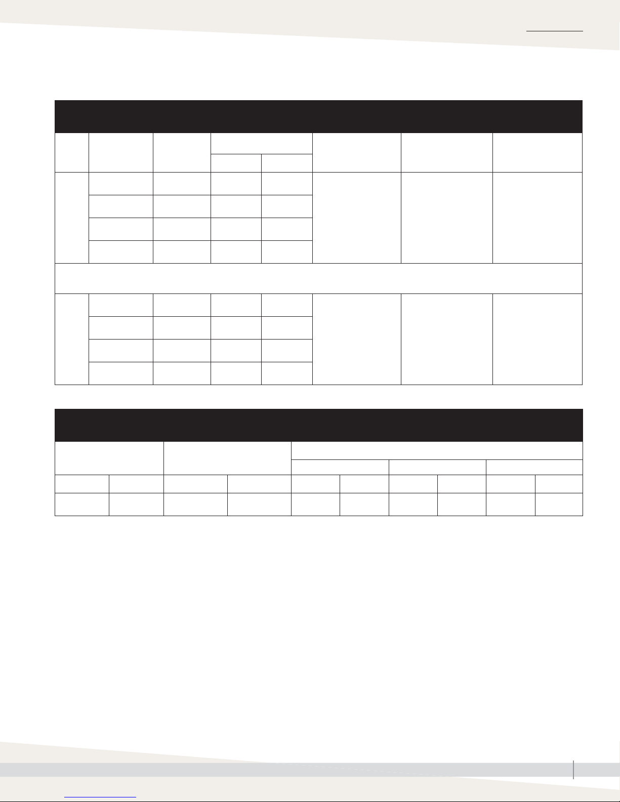
Voltages, weights, and dimensions
Table 5-1:
XTR humidifier capacities and electrical specifications
SPECIFICATIONS
Mode Voltage Input power
120V, 60 Hz 1.92 kW 5.6 2.5
208V, 60 Hz 3.33 kW 9.9 4.5
16 A
230V, 50 Hz 3.68 kW 10.8 4.9
240V, 60 Hz 3.84 kW 11.3 5.1
The XTR humidifi er can be confi gured to operate in a current limited mode if lower maximum operating capacity is desired.
See page 15 for setting this option.
120V, 60 Hz 1.38 kW 4.0 1.8
11.5 A
mc_050712_1408
208V, 60 Hz 2.39 kW 7.1 3.2
230V, 50 Hz 2.65 kW 7.8 3.5
240V, 60 Hz 2.76 kW 8.1 3.6
Nominal steam capacity
Nominal current draw Maximum line current Fuse
lbs/hr kg/h
16 A 19.2 A 25 A
11.5 A 13.8 A 25 A
Table 5-2:
XTR humidifier weights and dimensions
Shipping weight Maximum operating weight
Width Height Depth
lbs kg lbs kg inches mm inches mm inches mm
27.0 12.2 23.0 10.4 10-1/8 257 20-7/8 530 7-1/8 181
mc_050712_1409
Dimensions
XTR INSTALLATION, OPERATION, AND MAINTENANCE MANUAL
5
Page 10
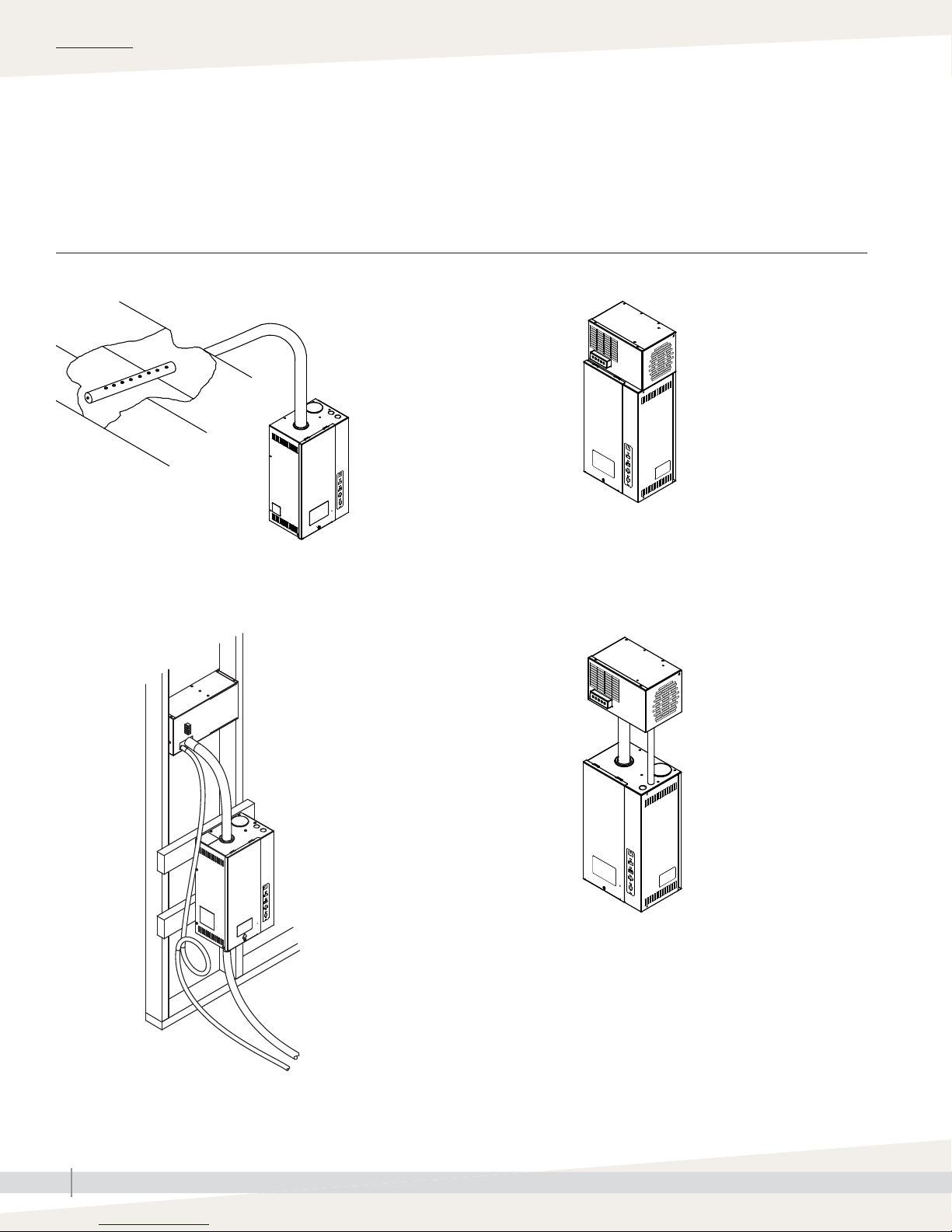
INSTALLATION
Dispersion options
The dispersion options in Figure 6-1 are available for XTR humidifi ers. For
installation details, see “Dispersion” beginning on Page 7.
FIGURE 6-1: XTR HUMIDIFIER DISPERSION OPTIONS
XTR dispersion tube in a duct
OM-7718
XTR steam blower mounted on top of humidifi er
OM-7720
XTR fan pack Remote-mounted XTR steam blower
90-1796
XTR INSTALLATION, OPERATION, AND MAINTENANCE MANUAL
6
OM-7719
Page 11
Selecting a location
INSTALLATION
HUMIDIFIER
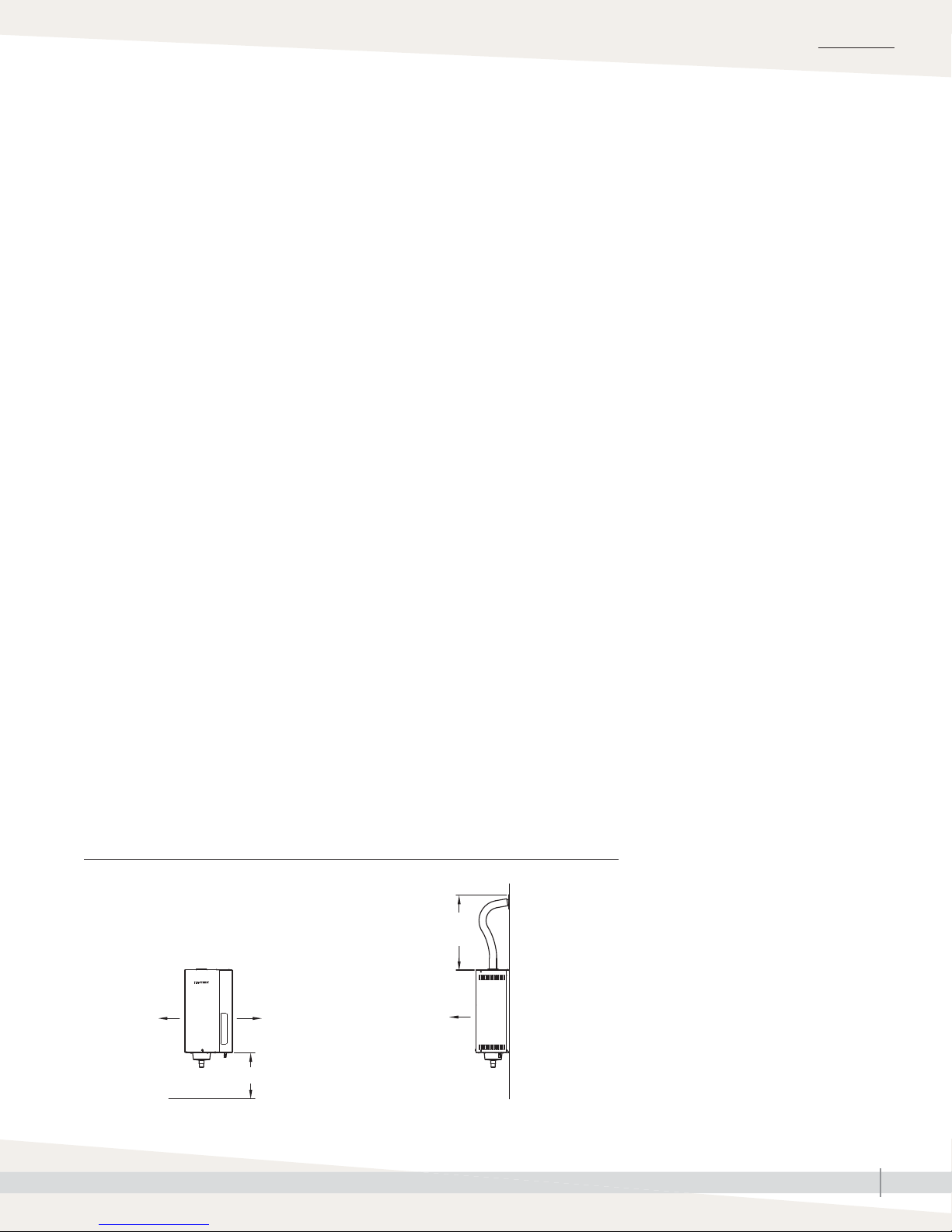
When selecting a location for the humidifi er, consider the following:
• Proximity to duct
Install the humidifi er near the duct. The maximum recommended length for
steam hose connecting an XTR humidifi er to a dispersion tube is 6' (1.8 m).
See “Dispersion” beginning on Page 20.
• Elevation of installed dispersion assembly
The recommended installation location for the dispersion device is at an
elevation higher than the humidifi er. However, if the dispersion device must
be installed at an elevation lower than the humidifi er, install a drip tee and
drain, as shown in Figure 19-3.
• Temperature and relative humidity (RH):
Install humidifi er only in locations that meet the following temperature and
RH requirements:
- Maximum ambient temperature: 104 °F (40 °C)
- Minimum ambient temperature: 41 °F (5 °C)
- Maximum ambient humidity: 80% RH (non-condensing)
• Recommended clearances (see Figure 7-1)
Control and dispersion devices
See “Sensor placement” on Page 18.
See “Dispersion” beginning on Page 20.
• Electrical connections
See “Field wiring” beginning on Page 12.
• Supply water and drain piping connections
See “Piping” on Page 9.
• Exterior wall insulation
Install the humidifi er on an exterior wall only if the wall is properly
insulated.
FIGURE 7-1: XTR HUMIDIFIER RECOMMENDED MINIMUM CLEARANCES
Side
4" (102 mm)
Front
16" (406
mm) for
electrical
clearance
16" (406 mm)
for steam hose
30" (762 mm)
for service
access
16" (406 mm) for drain
90-1702X
mc_050712_1405
XTR INSTALLATION, OPERATION, AND MAINTENANCE MANUAL
7
Page 12
INSTALLATION
Mounting
REMOVING COVERS AND STEAM CYLINDER
1. Unpack humidifier from shipping carton, and remove front cover by
removing screw and lifting cover up and away from humidifier.
2. If any wires are connected to top cylinder, pull straight up on plugs to
disconnect them from pins.
3. Remove cylinder and any packaging from inside of humidifier cabinet.
4. Remove two screws on right side of humidifier and remove side cover to
expose electrical compartment.
WALL MOUNTING HUMIDIFIER
The XTR humidifi er weighs 23 lbs (10.5 kg) with a full cylinder. Make sure the
mounting system will support its weight. Secure humidifi er to sturdy wall or to
sheet metal duct. If mounting to stud frame wall:
1. Install two spanner boards spanning two studs. Position top spanner board
so it will align with top of cabinet, and center bottom spanner board on
bottom mounting holes. See mounting holes in Figure 8-1.
WARNING
Mounting hazard
Mount humidifi er per the instructions
in this manual and to a structurally
stable surface. Improper mounting of
the humidifi er can cause it to fall or tip,
resulting in severe personal injury or
death.
mc_060110_1540
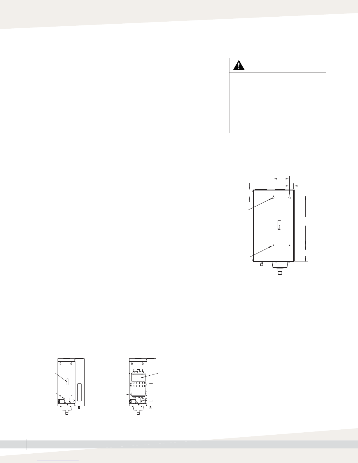
FIGURE 8-1: XTR HUMIDIFIER
MOUNTING HOLES
1-1/2" (38 mm)
4" (102 mm)
1" (25 mm)
2. Predrill holes in spanner boards, and secure humidifier to spanner boards
with screws provided.
Note: Use appropriate mounting methods and mounting hardware for other
mounting surfaces.
INSTALLING STEAM CYLINDER
1. Verify that O-ring is in place in slot of drain body. See Figure 8-2.
2. Use water to lubricate drain outlet on bottom of cylinder and O-ring in
drain valve body. Do not use oil, grease or any lubricant.
3. Insert cylinder drain outlet into drain valve body, and rotate cylinder so
Warning label is visible.
4. Attach the two electrode wires (they are interchangeable) and high water
sensor wire to pins on top of cylinder. Make sure plugs fit snugly and are
fully engaged on pins.
FIGURE 8-2: XTR STEAM CYLINDER INSTALLATION
Front view of cabinet
without cylinder
Front view of cabinet
with cylinder installed
Mounting
keyholes
Mounting
holes
90-1701-dims
mc_050712_1404
12" (305 mm)
4" (102 mm)
Cylinder guide
Drain valve body
XTR INSTALLATION, OPERATION, AND MAINTENANCE MANUAL
8
Cylinder
Warning label
OM-7721
Page 13
INSTALLATION
Piping:
SUPPLY WATER QUALITY
Supply water and drain
XTR humidifi ers use tap water to generate humidifi cation steam. Recommended
supply water conductivity for DriSteem electrode humidifi ers is 125 to 1250
μS/cm (roughly comparable to water hardness of 3 to 36 grains per gallon).
Do not use demineralized water. Do not use heated supply water, because
unheated supply water is required for drain water tempering.
SUPPLY WATER PIPING
Use only copper for supply water piping—do not use rubber or plastic. The fi ll
valve connection size is a 1/4" (DN8) compression fi tting.
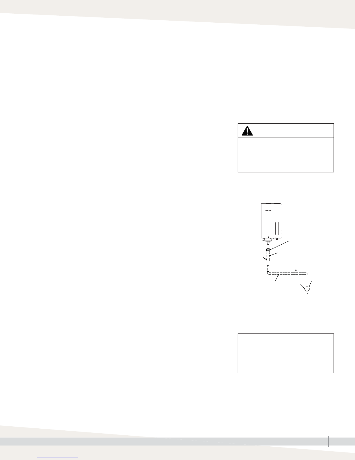
HUMIDIFIER DRAIN PIPING
Drain piping must be code-approved copper or steel rated for 212 °F (100 °C)
minimum. The fi nal connection size is 3/4" (DN20) copper for the steam
cylinder drain. Do not reduce this connection size. See Figure 9-1.
If drainage by gravity is not possible, use a condensate pump rated for 212 °F
(100 °C) water.
ACTIVATING AUTOMATIC DRAIN WATER TEMPERING
The XTR humidifi er is shipped with drain water tempering set to OFF. To
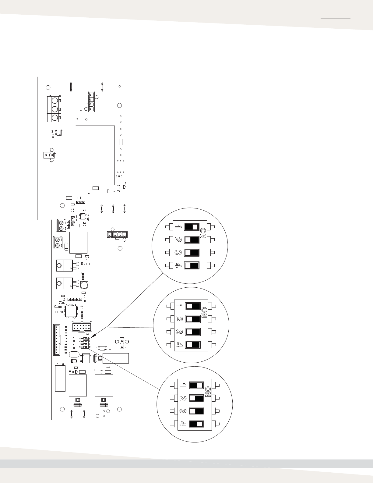
activate automatic drain water tempering, locate the DIP switch #4 on the
control board, and place it in the ON position as shown in Figure 15-1.
Note: Control board location is shown in Figure 42-1.
Important:
Thoroughly fl ush the supply water piping
to remove pipe residue and stagnant water
before connecting piping to the humidifi er.
Pipe residue and stagnant water in the water
supply piping can cause foaming, preventing
the humidifi er from reaching the required steam
capacity.
WARNING
Hot drain pipes
Drain piping surface may be hot.
Touching or contact with hot pipe may
cause severe personal injury.
FIGURE 9-1: DRAIN PIPING DETAIL
Drain cup
Hose clamp
(fi eld supplied)
Hose clamp
(fi eld supplied)
Black rubber hose
Pitch 1/8"/ft (1%) toward drain
OM-7499X
3/4" (DN20) copper
Note: Dashed lines indicate provided by
installer.
mc_050812_1111
Open
drain
1"
(25 mm)
air gap
CAUTION
To prevent drain steam from
condensing on the cabinet, do not
install the drain under the humidifi er.
XTR INSTALLATION, OPERATION, AND MAINTENANCE MANUAL
9
Page 14
INSTALLATION
Piping:
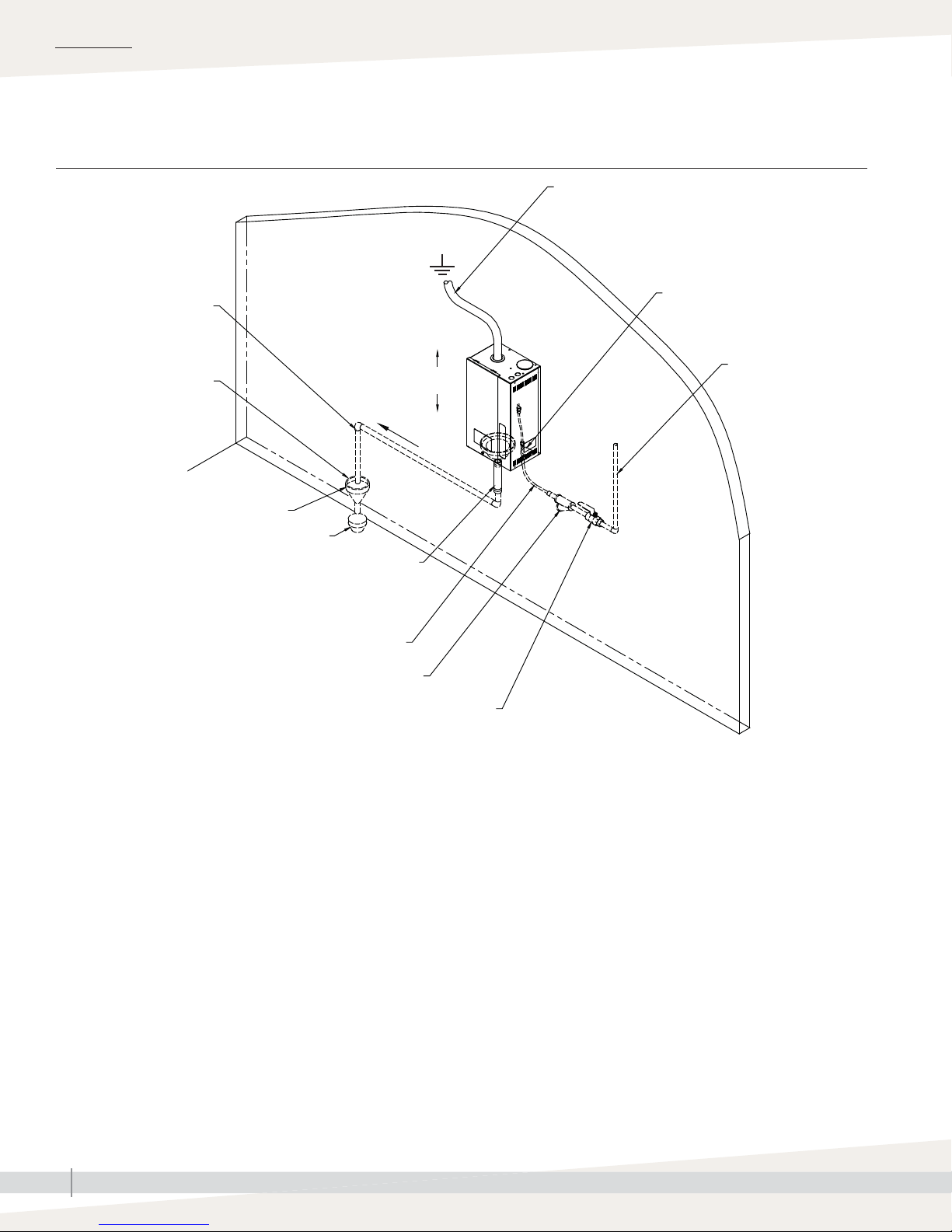
FIGURE 10-1: XTR HUMIDIFIER FIELD PIPING OVERVIEW
3/4" (DN20) metallic drain
piping. If piping run is over
10' (3 m) increase pipe to
1¼" (DN32).
1" (25 mm) air gap required
Open drain required. Locate air gap only in
spaces with adequate temperature and air
movement to absorb fl ash steam, or condensing
could occur on nearby surfaces. Refer to
governing codes for drain pipe size and
maximum discharge water temperature.
Field piping overview
Spill funnel; plumb to fl oor drain
Pitch 1/8”/ft (1%) toward drain
Install plumb
Hose and
clamps
Steam hose; may also use tubing. See Table 20-1 for
maximum lengths. Tubing must be grounded.
Fill valve (with screen)
Continuous copper
water supply line; water
pressure must be 25 to
80 psi (175 to 550 kPa)
1/4" (DN8) O.D. copper line
Inlet strainer, by installer
Note: Dashed lines indicate provided by installer.
mc_050812_1110
Supply valve, by installer
OM-7722
XTR INSTALLATION, OPERATION, AND MAINTENANCE MANUAL
10
Page 15

INSTALLATION
Piping:
FIGURE 11-1: PIPING CONNECTIONS TO XTR STEAM BLOWER
XTR steam blower and XTR fan pack
XTR steam blower mounted remotely XTR steam blower mounted directly on top of XTR humidifi er
Hose clamp (supplied with
Hose clamp (supplied with
humidifi er)
Steam hose, 6' (1.8 m) long
(supplied with humidifi er)
Hose clamp (supplied with
humidifi er)
OM-7723
mc_050912_1130
steam blower)
Steam hose (supplied with
steam blower)
Hose clamp (supplied with
humidifi er)
OM-7724
FIGURE 11-2: PIPING CONNECTIONS TO XTR FAN PACK
Fan pack
Steam hose
(provided with humidifi er)
XTR humidifi er
Condensate drain
hose, 3/8" ID
(provided with fan
pack)
To drain
Note: Dashed lines indicate provided by installer.
mc_050912_1131
Grille
(front of fan pack)
Wall
90-1551
XTR humidifi er drain
Back view of fan packSide view of wall
90-1560
Condensate drain
hose connection
Steam hose connection
XTR INSTALLATION, OPERATION, AND MAINTENANCE MANUAL
11
Page 16
INSTALLATION
Field wiring
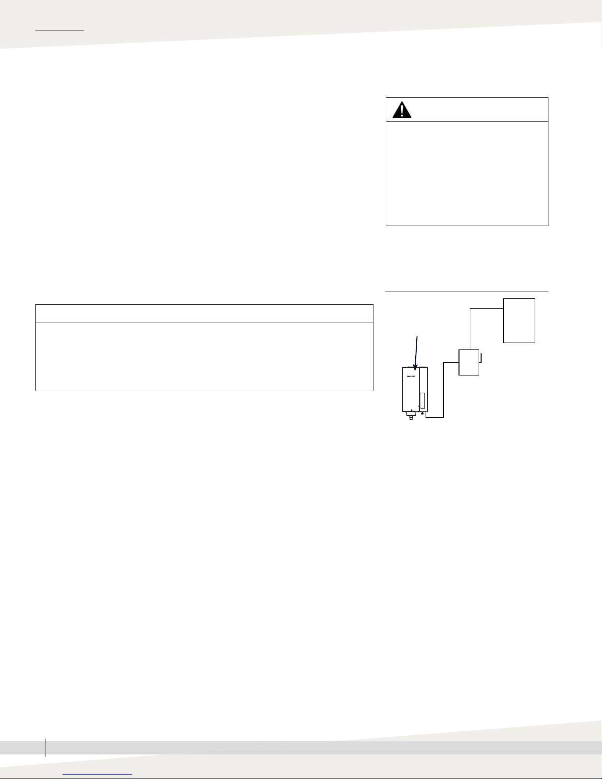
All wiring must be code approved and in accordance with the unit wiring
diagram. Power supply wiring must be rated for 220 °F (105 °C). See Figure
12-1 for the humidifi er wiring diagram location.
When selecting a location for installing the humidifi er:
• Avoid areas close to sources of electromagnetic emissions such as power
distribution transformers.
• Do not loop power wiring.
• Do not use aluminum wire.
CONDUIT KNOCKOUTS
Conduit knockouts are provided on top and bottom of the cabinet. Control
wiring knockouts are toward the top front; power wiring knockouts are on the
top rear.
WARNING
Electric shock hazard
Only qualifi ed electrical personnel
should perform fi eld wiring installation
procedures. Improper wiring or contact
with energized circuits may cause
property damage, severe personal
injury, or death as a result of electric
shock and/or fi re.
FIGURE 12-1:
FIELD WIRING REQUIREMENTS
CAUTION
Adding conduit connections not recommended
Adding alternate conduit connections is not recommended. If you must make
additional holes in the humidifi er cabinet, protect all internal components from
debris, and vacuum out the cabinet when fi nished. Failure to follow these precautions
can damage sensitive electronic components and void the DriSteem warranty.
FIELD WIRING CONNECTION INSTRUCTIONS
• Connect to line power.
XTR humidifi er is shipped confi gured for 230V or 240V. To confi gure for
120V or 208V, refer to wiring diagram on humidifi er subpanel and inside
of humidifi er side cover.
See Table 5-1 and the data plate on outside of cabinet for nominal current
draw, maximum line current, and recommended fusing.
• Connect to control signal wiring from a humidistat. See note below.
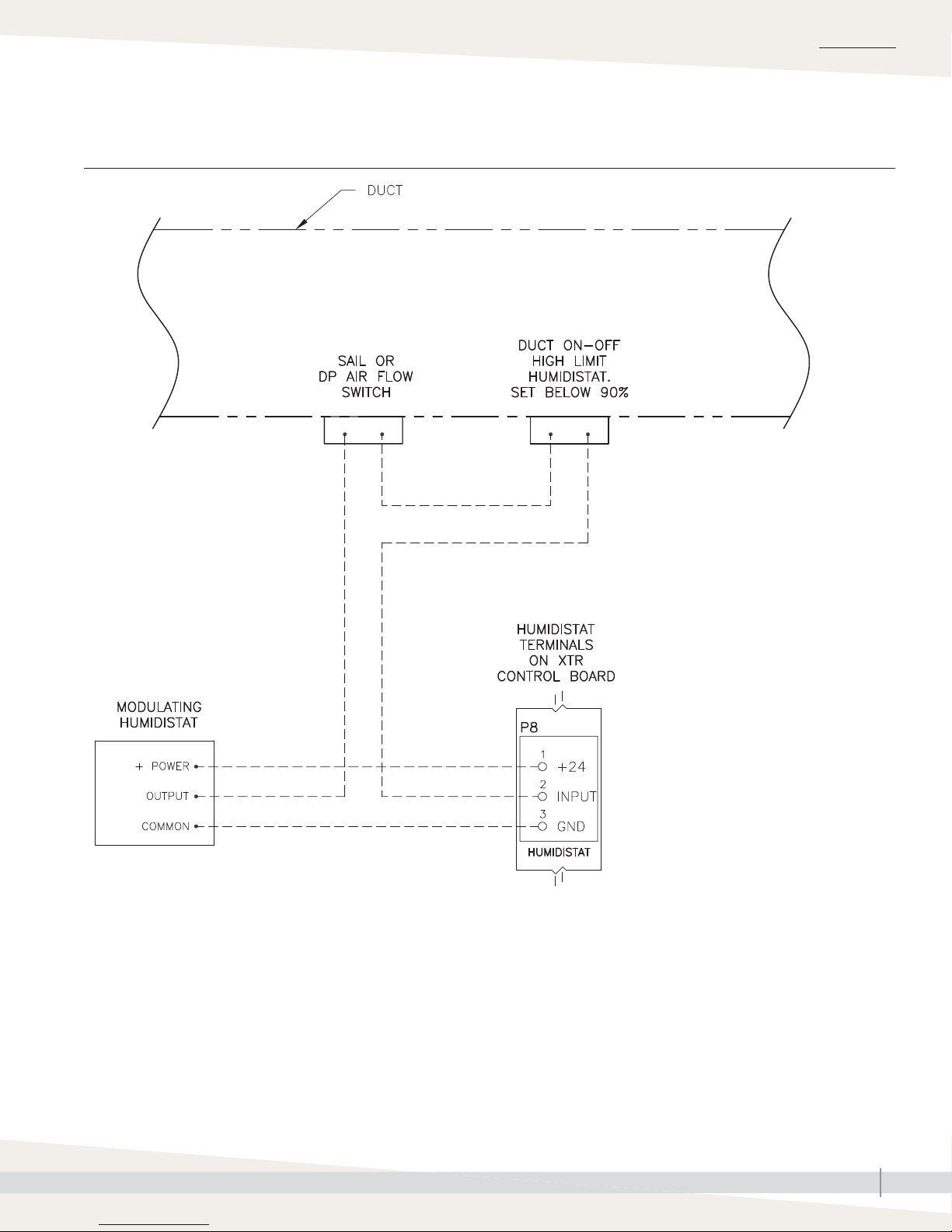
• Connect to duct airfl ow proving switch and duct high limit humidistat wiring
(recommended optional devices). See note below.
Note: See recommended control wiring in Figure 14-1.
Wiring diagram
inside of front cover
Power supply
Fused disconnect
OM-7692X
XTR humidifi er
Notes:
• Control wiring and power wiring must be
run in dedicated or separate earthed metal
conduit, cable trays, or trunking.
• Separate line-voltage wiring from low-voltage
control circuit wiring when routing electrical
wiring inside humidifi er cabinet.
• Do not use chassis or safety grounds as
current-carrying commons. Never use a
safety ground as a conductor or neutral to
return circuit current.
• For circuit protection requirements, see
recommended fusing in Table 5-1.
XTR INSTALLATION, OPERATION, AND MAINTENANCE MANUAL
12
Page 17

Field wiring
EARTH GROUNDING REQUIREMENTS
A code-approved safety earth grounding system is required. The ground
connection must be made with solid metal-to-metal connections. Ground wire
should be the same size as power wiring.
CONTROL COMPONENT PLACEMENT
Follow the guidelines on Page 18 for placing humidistats, transmitters, and
airfl ow proving switches.
CONTROL INPUT WIRING
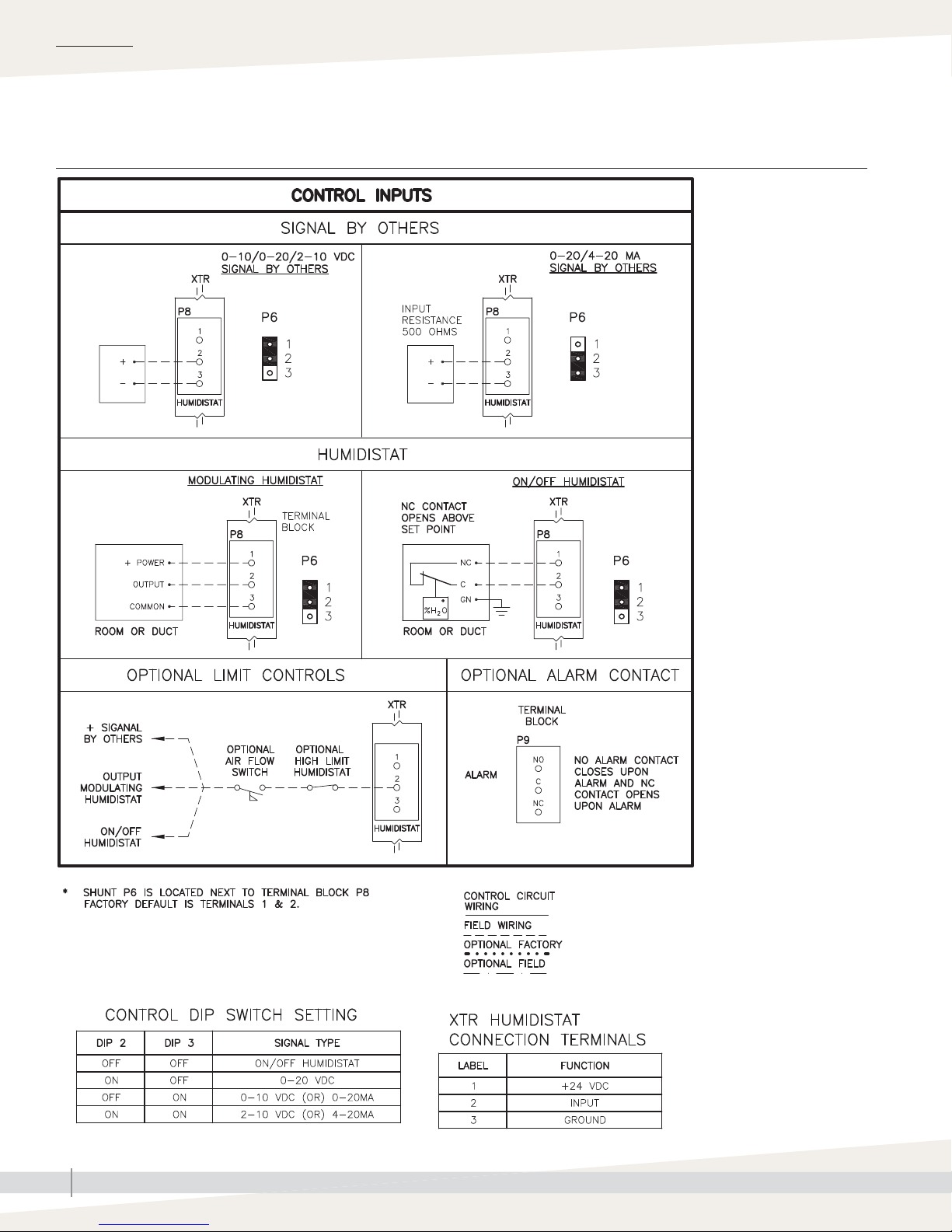
XTR humidifi ers accept RH signals from DriSteem control components. For
wiring connection requirements, fi rst determine which control scenario applies.
Then, refer to the control input wiring diagram in the humidifi er cabinet.
INSTALLATION
WARNING
Excessive moisture hazard
DriSteem strongly recommends
installing a duct airfl ow proving switch
and a duct high limit humidistat. These
devices prevent a humidifi er from
making steam when there is low airfl ow
in the duct or when the RH level in the
duct is too high. Failure to install these
devices can result in excessive moisture
in the duct, which can cause bacteria
and mold growth or dripping through
the duct.
mc_060310_0725
Proper wiring prevents electrical noise.
Electrical noise can produce undesirable effects
on electronic control circuits, which affects
controllability. Electrical noise is generated
by electrical equipment such as inductive
loads, electric motors, solenoid coils, welding
machinery, or fl uorescent light circuits. The
electrical noise or interference generated from
these sources (and the effect on controllers)
is diffi cult to defi ne, but the most common
symptoms are erratic control or intermittent
operational problems.
Important:
• For maximum EMC effectiveness, wire all
humidity, high limit, and airflow controls
using multicolored shielded/screened
plenum-rated cable with a drain wire for
the shield/screen. Connect the drain wire
to the shield/screen ground terminal with
wire less than 2" (50 mm) in length.
• Do not ground shield at the device end.
XTR INSTALLATION, OPERATION, AND MAINTENANCE MANUAL
13
Page 18
INSTALLATION
Field wiring
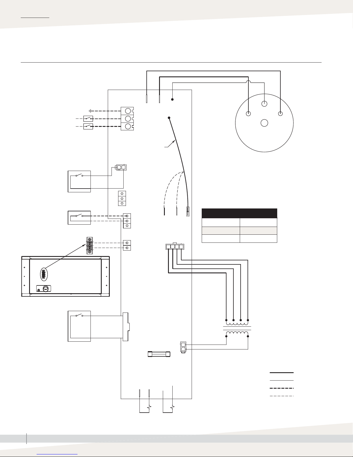
FIGURE 14-1: XTR CONTROL BOARD WIRING
POWER
TERMINAL
BLOCK
TRANSFORMER POWER
P7
NO
COM
NC
ALARM
HUMIDISTAT
DRY
CONTACT
FAN PACK
(OPTIONAL)
MAIN POWER BREAKER
(NOT PROVIDED)
GND
L2 / N
L1
DOOR SWITCH
ORANGE
ON/OFF HUMIDITY
CONTROL*
24 VAC
FAN PACK
BLK
J8
J10
JUMPER WIRE
BLK/WHT
BLK
VAC
J11
120
J16
YEL
VAC
J13
208
J14
240
VAC
ORG
RED
BLK
WHT
WATER LEVEL
ELECTRODE
STEAM HUMIDIFIER
IS SHIPPED FROM THE FACTORY
WIRED FOR 240 VOLTS.
MOVE THE TRANSFORMER POWER JUMPER WIRE TO
TERMINAL J11 OR J13 BASED ON INPUT POWER.
PROBE
STEAM CANISTER
Input power Terminal
120 VAC J11
208 VAC J13
230/240 VAC J14
P3
ELECTRODE
DISPLAY PANEL
RIBBON CABLE
XTR INSTALLATION, OPERATION, AND MAINTENANCE MANUAL
14
J2
10
TRANSFORMER
YEL
FILL
P4
BLUE
YEL
HIGH VOLTAGE WIRING
CONTROL CIRCUIT WIRING
HIGH VOLTAGE FIELD WIRING
LOW VOLTAGE FIELD WIRING
* SEE PAGE 16 FOR MODULATING HUMIDISTAT FIELD WIRING.
90-1903b
1
SLOW BLOW FUSE
J5 J6
BLK
DRAIN
VALVE
(5X20mm 5A)
CON1
VALVE
Page 19
Field wiring
FIGURE 15-1: XTR CONTROL BOARD
INSTALLATION
OM-7802a
Factory setting for
16.0 AMP nominal
operation and disabled
drain tempering function.
Slide DIP Switch #1
to “OFF” position
for 11.5 AMP
nominal operation.
Slide DIP Switch #4
to “ON” position
to enable drain
tempering function.
XTR INSTALLATION, OPERATION, AND MAINTENANCE MANUAL
15
Page 20
INSTALLATION
Field wiring
FIGURE 16-1: XTR EXTERNAL CONTROL CONNECTIONS
XTR INSTALLATION, OPERATION, AND MAINTENANCE MANUAL
16
XTR-2
Page 21
Field wiring
FIGURE 17-1: TYPICAL MODULATING CONTROL WIRING
INSTALLATION
OM-7834
XTR INSTALLATION, OPERATION, AND MAINTENANCE MANUAL
17
Page 22

INSTALLATION
Sensor placement
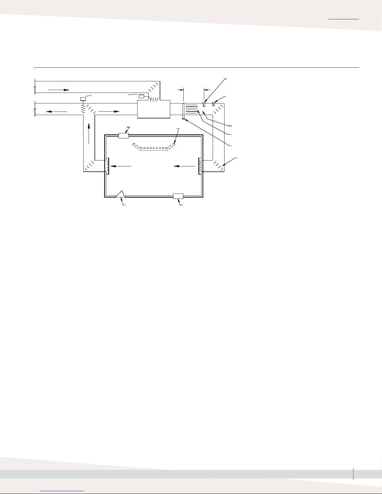
SENSOR LOCATION IS CRITICAL
Sensor location has a signifi cant impact on humidifi er performance. See the
recommendations below and Figure 15-1.
Note: Use humidity sensing devices only in their intended location. Room
humidity devices are calibrated with zero or little airfl ow, whereas duct
humidity devices require air passing across them.
Recommended humidity control (transmitter/humidistat) locations:
A. Ideal. Ensures the best uniform mix of dry and moist air with stable
temperature control.
B. Acceptable, but room environment can affect controllability, such as when
sensor is too close to air grilles, registers, or heat radiation from room
lighting.
C. Acceptable. Provides uniform mixture of dry and moist air. If extended time
lag exists between humidity generation and sensing, extend sampling time.
D. Acceptable (behind wall or partition) for sampling entire room if sensor is
near an air exhaust return outlet. Typical placement for sampling a critical
area.
E. Not acceptable. These locations might not represent actual overall
conditions in the space.
Other factors affecting humidity control
Humidity control involves more than the
controller’s ability to control the system. Other
factors that play an important role in overall
system control are:
• Size of humidification system relative to
load
• Overall system dynamics associated with
moisture migration time lags
• Accuracy of humidistats and humidity
transmitters and their location
• Dry bulb temperature accuracy in space
or duct
• Velocities and airflow patterns in ducts
and space environments
• Electrical noise or interference
mc_072011_1656
F. Not acceptable. Do not place sensors near windows, door passageways,
or areas of stagnant airfl ow.
Recommended safety (airfl ow and high limit) sensor location:
G. Best sensing location for high limit humidistat or humidity sensor and airfl ow
proving switch.
mc_072011_1655
XTR INSTALLATION, OPERATION, AND MAINTENANCE MANUAL
18
Page 23
Sensor placement
FIGURE 19-1: RECOMMENDED SENSOR LOCATIONS
INSTALLATION
Outside air
Relief air
Damper control
Return air
Window
E
s
A
s
Air handling
C
s
Wall or partition
F
Doorway
unit
s
8' to 12'
(2.4 m to 3.7 m)
min.
G
s
D
s
B
E
s
F
E
s
Window
DC-1084
mc_060508_0750-XT
High limit humidistat or high limit transmitter (set at 90% RH
maximum) for VAV applications
Airfl ow switch or differential pressure switch (sail type
recommended for VAV applications)
Vapor absorption has taken place
Point of vapor absorption
Humidifi er dispersion assembly
Turning vanes
XTR INSTALLATION, OPERATION, AND MAINTENANCE MANUAL
19
Page 24
INSTALLATION
Dispersion:
Selecting the location
For XTR steam blower and XTR fan pack location information, go to the page
indicated below:
• XTR steam blower: Instructions begin on Page 24
• XTR fan pack: Instructions begin on Page 27
The XTR dispersion tube must be positioned in the duct where water vapor
being discharged is carried off with the airstream and absorbed before it
can cause condensation or dripping. DriSteem documents distances required
for non-wetting to occur. Find more information about absorption non-wetting
distances at www.dristeem.com.
• In general, dispersion tube is best placed where air can absorb moisture
being added without causing con den sa tion at or after dispersion tube. This
normally will be after heating coil or where air tem per a ture is highest.
• Place dispersion tube such that absorption will occur
– before intake of a high effi ciency fi lter, because fi lter can remove visible
moisture and become waterlogged;
– before coming in contact with any metal surface;
– before fi re or smoke detection devices;
– before split in duct; otherwise, dispersion tube can direct more moisture
into one duct than the other.
Important:
Failure to follow the recommendations in this
section can result in excessive back pressure on
the humidifi er. This will result in unacceptable
humidifi cation system performance such as
leaking gaskets, blown water seals, erratic
water level control, and spitting condensate
from dispersion tubes.
mc_060210_0843
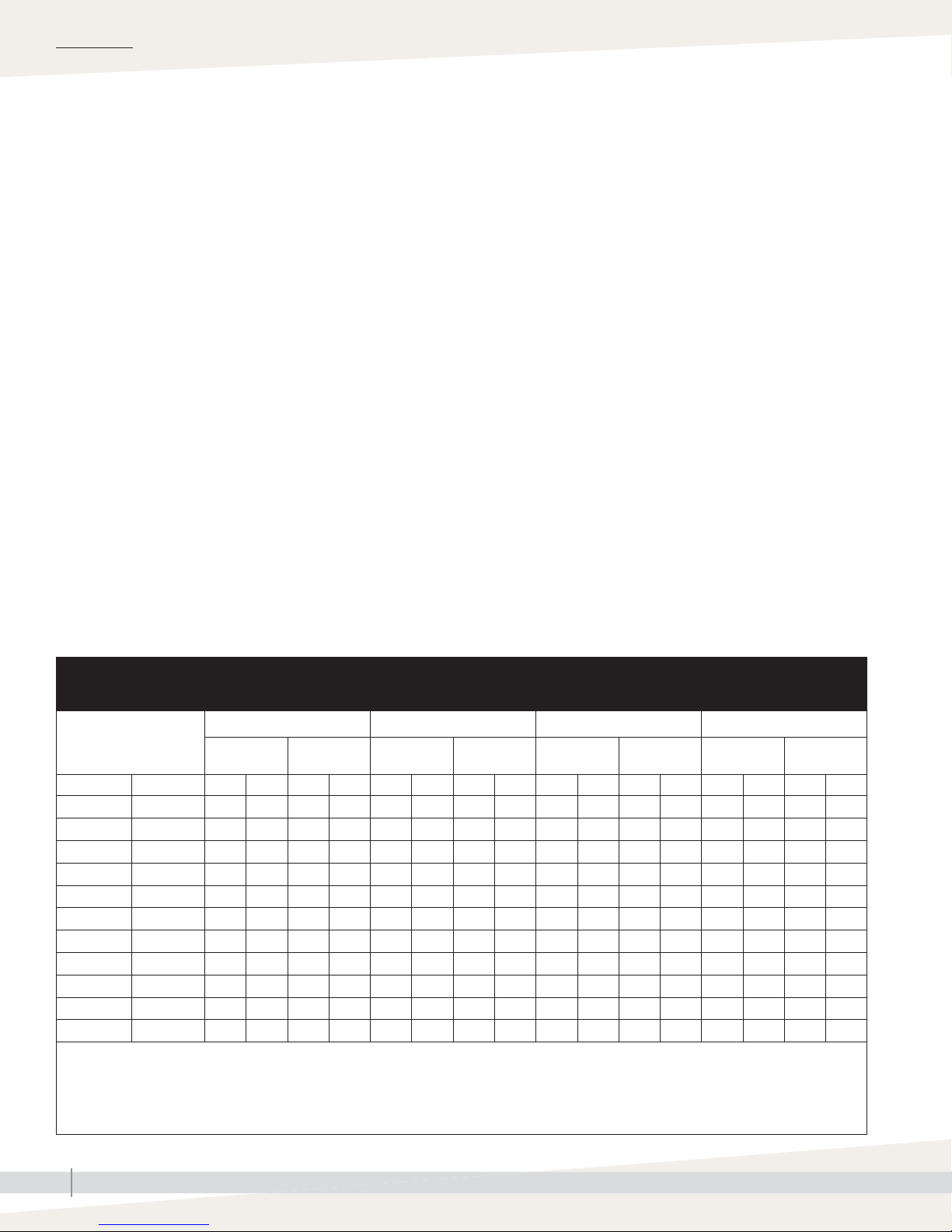
Table 20-1:
Maximum steam carrying capacity and length of interconnecting steam hose and tubing
Developed length
of steam hose or
insulated tubing*
ft m lbs/hr kg/h lbs/hr kg/h lbs/hr kg/h lbs/hr kg/h lbs/hr kg/h lbs/hr kg/h lbs/hr kg/h lbs/hr kg/h
< 2 < 0.6 4.0 1.8 4.0 1.8 7.1 3.2 7.1 3.2 7.8 3.5 7.8 3.5 8.1 3.7 8.1 3.7
2 0.6 3.8 1.7 3.8 1.7 7.0 3.2 7.0 3.2 7.7 3.5 7.7 3.5 8.0 3.6 8.0 3.6
4 1.2 3.5 1.6 3.8 1.7 6.6 3.0 7.0 3.2 7.3 3.3 7.7 3.5 7.6 3.4 8.0 3.6
6 1.8 3.1 1.4 3.8 1.7 6.3 2.9 7.0 3.2 7.0 3.2 7.3 3.3 7.3 3.3 7.6 3.4
8 2.4 — — 3.5 1.6 — — 6.6 3.0 — — 7.3 3.3 — — 7.6 3.4
10 3.0 — — 3.5 1.6 — — 6.6 3.0 — — 7.3 3.3 — — 7.6 3.4
12 3.7 — — 3.5 1.6 — — 6.6 3.0 — — 7.3 3.3 — — 7.6 3.4
14 4.3 — — 3.1 1.4 — — 6.3 2.9 — — 7.0 3.2 — — 7.3 3.3
16 4.9 — — 3.1 1.4 — — 6.3 2.9 — — 7.0 3.2 — — 7.3 3.3
18 5.5 — — 3.1 1.4 — — 6.3 2.9 — — 7.0 3.2 — — 7.3 3.3
20 6.1 — — 3.1 1.4 — — 6.3 2.9 — — 6.7 3.0 — — 7.0 3.2
Notes:
* Developed length equals measured length plus 50% of measured length to account for fi ttings.
• DriSteem recommends 6' (1.8 m) maximum steam hose length pitched at 2"/ft (15%) toward humidifi er. Steam hose tends to sag if not supported
for its full length, which leads to collecting condensate and system pressure issues. Tubing sags less and can allow for 1/8"/ft (1%) pitch with
longer runs.
mc_050712_1445
120V, 60 Hz 208V, 60 Hz 230V, 50 Hz 240V, 60 Hz
Steam hose
Insulated
tubing
Steam hose
Insulated
tubing
Steam hose
Insulated
tubing
Steam hose
Insulated
tubing
XTR INSTALLATION, OPERATION, AND MAINTENANCE MANUAL
20
Page 25

INSTALLATION
Dispersion:
CONNECTING HUMIDIFIER TO DISPERSION DEVICE
Interconnecting piping requirements
• See Table 18-1 for interconnecting tubing and pitch requirements.
• Steam outlet on humidifi er is sized to output of humidifi er. Do not use
interconnecting tubing with inside diameter smaller than 7/8" (22 mm).
Reducing inside diameter of interconnecting piping will result in internal
humidifi er system pressure exceeding the parameters for acceptable
performance.
• See Table 16-1 for the maximum steam carrying capacities.
• If humidifi er must be located higher than dispersion tube, use recommend
installation shown Figure 19-1.
CONNECTING HUMIDIFIER TO DISPERSION DEVICE WITH STEAM HOSE
• Support steam hose to prevent sags or low spots.
• Use DriSteem steam hose. Other manufacturers of steam hose may use
unacceptable release agents or material mixes that can affect humidifi er
system performance adversely. Using hose from alternative manufacturers
increases the possibility of foaming in the cylinder and accelerated steam
hose aging. Foaming causes condensate discharge at the dispersion tube.
• Do not use steam hose in outdoor applications.
• Do not insulate steam hose. Insulation causes accelerated heat aging,
causing steam hose to become hard and susceptible to failure due to
cracks.
CONNECTING HUMIDIFIER TO DISPERSION DEVICE WITH TUBING
• 90° elbows are not recommended; use two 45° elbows, 1' (0.3 m) apart.
• Insulate tubing to reduce the loss in output caused by condensation.
WARNING
Hot surface and steam hazard
Dispersion device, steam hose, and
tubing can contain steam, and surfaces
can be hot. Discharged steam is not
visible.
To avoid burns, do not to touch
dispersion tube, front of steam blower,
or front of fan pack, and do not put any
part of body in front of steam outlets.
Avoid contact with hot surfaces and air
into which steam has been discharged.
mc_043012_0920
CAUTION
Each humidifi er requires its own steam
hose and dispersion tube. Do not
connect steam hoses from more than
one humidifi er together. Back-pressure
from one humidifi er can lower the
water level in the cylinder in the other
humidifi er and cause operational
problems.
Do not install the dispersion tube in a
duct with greater than 2" wc (498 Pa)
static pressure. High duct pressure can
cause back-pressure in the cylinder
which can result in unstable humidifi er
operation.
Condensate control and collection
Controlling condensate fl ow and collection
is critical to XTR humidifi er performance. To
maximize performance, follow all installation
recommendations for your specifi c humidifi er
voltage and dispersion device.
XTR INSTALLATION, OPERATION, AND MAINTENANCE MANUAL
21
Page 26
INSTALLATION
Dispersion:
XTR dispersion tube
If dispersing steam with the XTR steam blower or XTR fan pack, skip this
procedure and go to the page listed below.
• XTR steam blower: Instructions begin on Page 24
• XTR fan pack: Instructions begin on Page 27
DISTANCE FROM HUMIDIFIER TO XTR DISPERSION TUBE
The maximum recommended length of steam hose is 6' (1.8 m). Longer runs of
steam hose or tubing result in more condensation.
Note: If 6' (1.8 m) steam hose does not reach from humidifi er to dispersion
tube, extend run to a maximum of 20' (6 m) with copper tube as shown
in Figure 19-2. Insulate the tubing with 1" (25 mm) of fi berglass to
minimize loss of capacity and effi ciency.
INSTALLING DISPERSION TUBE IN DUCT
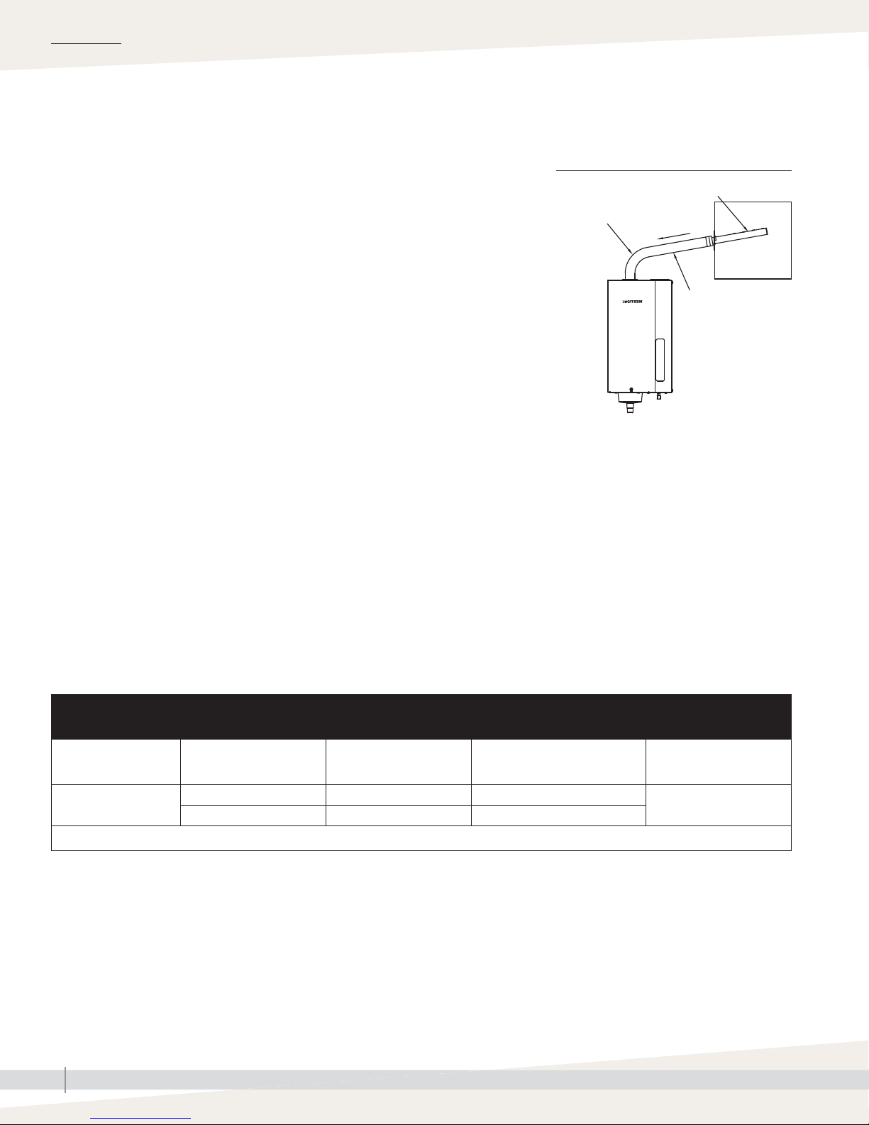
Make sure dispersion tube is mounted higher than humidifi er so condensate
that forms in tube runs back to cylinder. See Figure 22-1.
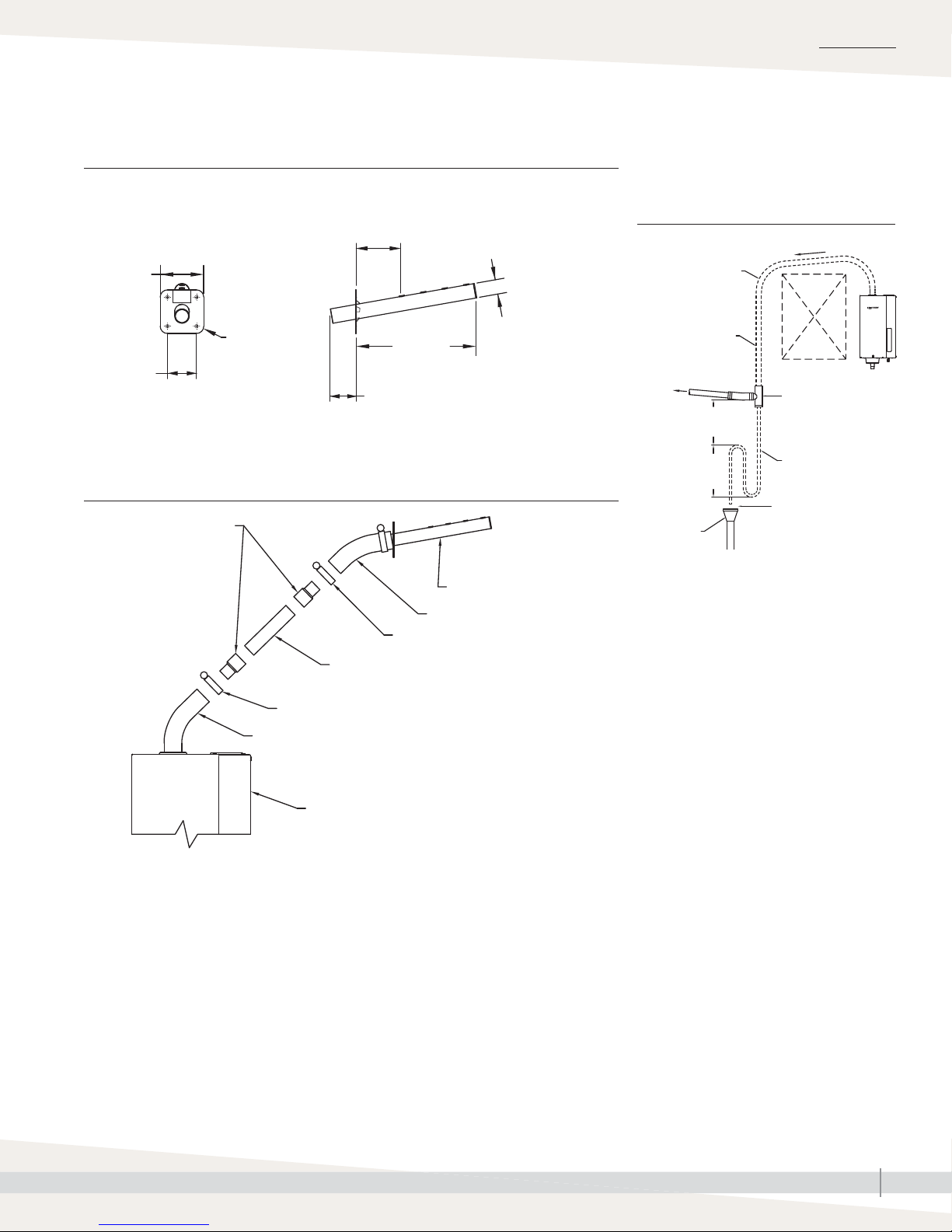
Note: If dispersion tube cannot be mounted higher than humidifi er, or if steam
hose must extend up from humidifi er then down to dispersion tube (due
to an obstruction), install a drip tee. See Figure 19-3.
FIGURE 22-1: XTR DISPERSION TUBE
MOUNTED HIGHER THAN HUMIDIFIER
90° long
sweep or two
45° elbows
90-1704X
* Pitch toward humidifi er:
• 2"/ft (15%) minimum when using steam hose
• 1/4"/ft (2%) when using tubing
mc_050912_0946
Dispersion tube
Pitch*
Duct
Steam hose or
tubing; insulate
tubing with 1"
(25 mm) fi berglass
to reduce steam
loss. Do not insulate
steam hose.
1. Drill 1-1/4" (32 mm) diameter hole in vertical surface of duct at location
chosen for dispersion tube.
2. Position dispersion tube so it is angled up, regardless of airflow direction.
Secure with four sheet metal screws provided.
Table 22-1:
Pitch of XTR dispersion tube and interconnecting piping*
Condensate drain
None
* When piping over an obstruction, see the drip tee installation illustration in Figure 19-1.
mc_050912_0945
Type of interconnecting
piping
Steam hose 7/8" (22 mm) 2"/ft (15%) toward humidifi er
Tubing 7/8" (22 mm) 1/8"/ft (1%) toward humidifi er
Diameter of dispersion tube
and interconnecting piping
Pitch of interconnecting piping Pitch of dispersion tube
2"/ft (15%) toward
humidifi er
XTR INSTALLATION, OPERATION, AND MAINTENANCE MANUAL
22
Page 27
INSTALLATION
Dispersion: XTR dispersion tube
FIGURE 23-1: XTR DISPERSION TUBE DIMENSIONS FIGURE 23-2: DRIP TEE INSTALLATION
FOR DISPERSION TUBE LOWER THAN
HUMIDIFIER (OR PIPING OVER AN
OBSTRUCTION)
Pitch
90° long sweep or
two 45° elbows
Insulate tubing to
reduce steam loss
To dispersion tube
6" (150 mm)
minimum
Obstruction
Tubing drip tee,
by installer
3" (76 mm)
2" (51 mm)
End view Side view
3" (76 mm)
(mounting plate to fi rst tubelet)
UP
Mounting
plate
90-1701-tube
8-1/4"
(210 mm)
1-3/4" (44 mm)
1" (25 mm)
FIGURE 23-3: EXTENDING DISTANCE FROM HUMIDIFIER TO DISPERSION TUBE
WITH COPPER TUBE
1" x 3/4" (DN25 x DN20)
reducer couplings
Dispersion tube
Steam hose
1½" (DN40) hose clamp
1" (DN25) copper tube, 20' (6 m) maximum
run length
1½" (DN40) hose clamp
Steam hose
XTR humidifi er
XTR-copper-pipe
mc_050912_0947
8" (200 mm)
minimum
Open drain
required (see
fi rst note
below)
Notes:
• Locate air gap only in spaces with adequate
temperature and air movement to absorb
fl ash steam; otherwise, condensation may
form on nearby surfaces. Refer to governing
codes for drain pipe size and maximum
discharge water temperature.
• Support steam hose so there are no sags or
low spots
• Dashed lines indicate provided by installer
mc_050912_1043
90-1703X
3/4" (DN20)
1" (25 mm) air gap
XTR INSTALLATION, OPERATION, AND MAINTENANCE MANUAL
23
Page 28
INSTALLATION
Dispersion:
XTR steam blower
XTR steam blowers are designed for use in fi nished spaces. They disperse steam
into large open spaces and are useful where there are no air-handling ducts.
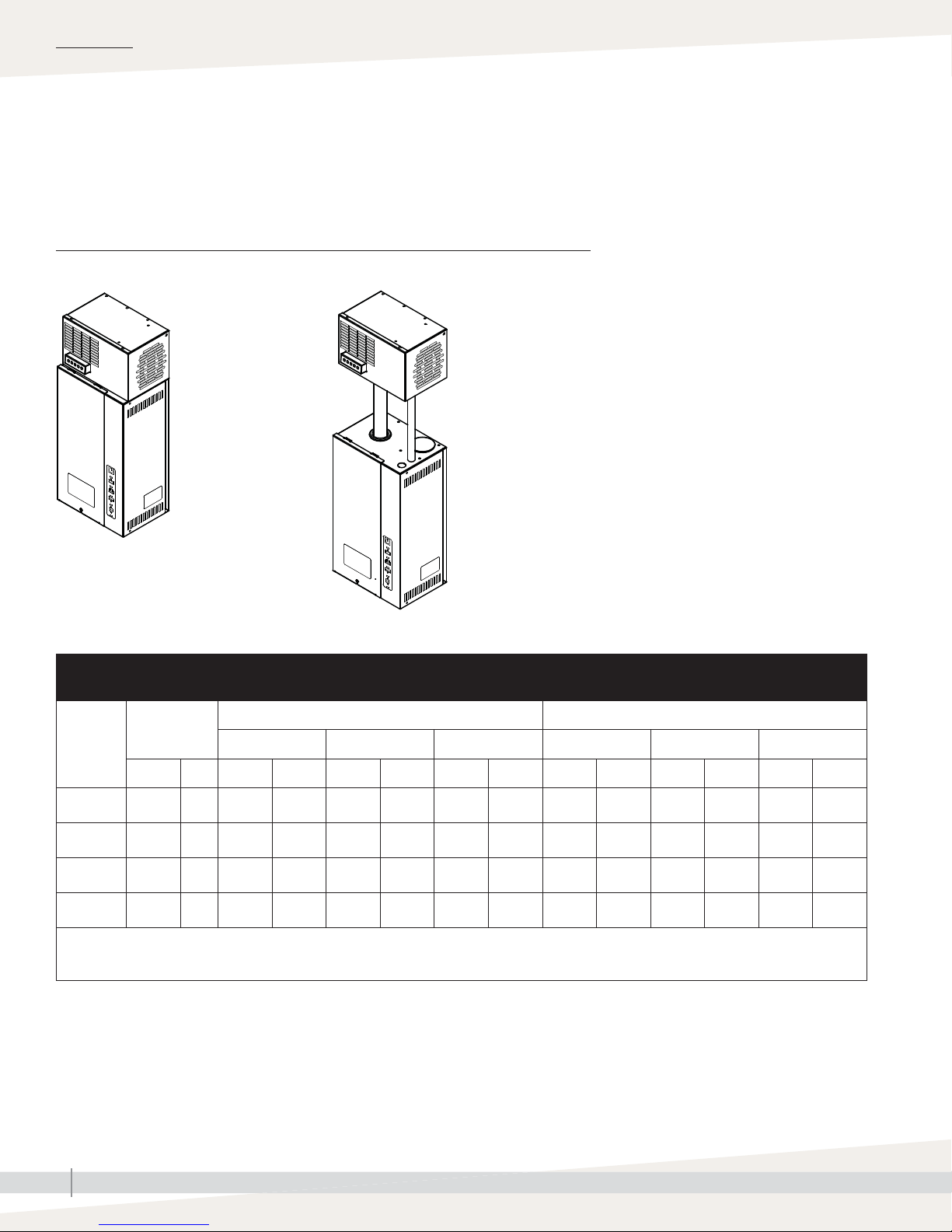
FIGURE 24-1: XTR STEAM BLOWER DISPERSION
Mounted on top of the humidifi er Mounted remotely from the humidifi er
XTR steam blower
XTR humidifi er
OM-7720
XTR steam blower
Maximum recommended
distance between
humidifi er and XTR steam
blower is 6' (1.8 m).
XTR humidifi er
OM-7719
mc_050712_1411
Table 24-1:
XTR steam blower rise, spread, and throw non-wetting distances for 16.0 Amp current mode
Maximum
XTR
humidifi er
voltage
120 5.6 2.5 1.4 0.4 1.2 0.4 3.8 1.2 2.4 0.7 1.4 0.4 5.2 1.6
208 9.9 4.5 2.4 0.7 1.4 0.4 4.1 1.3 3.2 1.0 1.6 0.5 5.7 1.7
230 10.8 4.9 2.8 0.9 1.5 0.5 4.3 1.3 3.5 1.1 1.7 0.5 6.1 1.9
240 11.3 5.1 2.9 0.9 1.5 0.5 4.3 1.3 3.6 1.1 1.7 0.5 6.2 1.9
Rise: Minimum non-wetting height above steam outlet of steam blower
Spread: Minimum non-wetting width from steam outlet of steam blower
Throw: Minimum non-wetting horizontal distance from steam outlet of steam blower
mc_050712_1412
steam
capacity
lbs/hr kg/h ft m ft m ft m ft m ft m ft m
Rise Spread Throw Rise Spread Throw
30% RH @ 70 ºF (21 ºC) 50% RH @ 70 ºF (21 ºC)
XTR INSTALLATION, OPERATION, AND MAINTENANCE MANUAL
24
Page 29
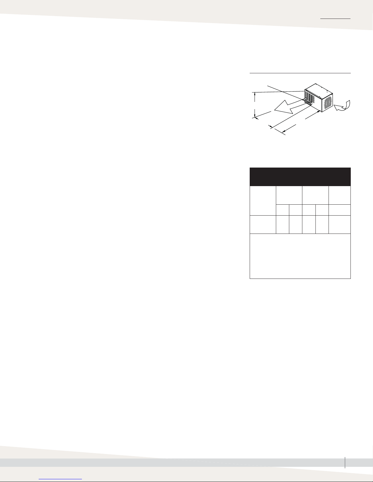
Dispersion: XTR steam blower
INSTALLATION
On a call for humidity the XTR humidifi er produces steam and provides power
to the XTR steam blower. The steam blower distributes the steam to the room.
When the call for humidity ends and the humidifi er stops producing steam,
the steam blower operates for another two minutes to distribute the remaining
steam before deactivating.
As steam is discharged from the steam blower, it quickly cools and turns to a
visible fog that is lighter than air. As this fog is carried away from the steam
blower by the airstream, it tends to rise toward the ceiling. If the fog contacts
solid surfaces (columns, beams, ceiling, pipes, etc.) before it disappears, it
could condense and drip. The greater the space relative humidity, the further
the fog will rise, spread, and throw.
Table 20-1 lists the maximum rise, spread, and throw non-wetting distances
for XTR humidifi ers with XTR steam blowers. Surfaces cooler than ambient
temperature, or objects located within this minimum dimension, could cause
condensation and dripping. To avoid steam impingement on surrounding
areas, observe the minimum non-wetting distances in the table.
DISTANCE FROM HUMIDIFIER TO XTR STEAM BLOWER
The maximum recommended length of steam hose is 6' (1.8 m). Longer runs of
steam hose or tubing result in more condensation.
MOUNTING
The XTR steam blower can be mounted directly on top of an XTR humidifi er or
remotely from the humidifi er. See Figure 20-1. Installation must comply with
governing codes.
Mount the steam blower so that it is plumb. When mounting on a wood stud
wall, locate studs and attach spanner board. Mark hole locations (see Figure
25-1) and predrill 1/8" (3 mm) diameter pilot holes. Secure with screws
provided.
FIGURE 25-1: XTR STEAM BLOWER RISE,
SPREAD, THROW
Steam outlet
OM-7725
Rise
Air
Spread
mc_050712_1415
Throw
intake
grille
Table 25-1:
XTR steam blower specifications
Steam
blower
model
SDU-003E 8.8 4.0 6.8 3.1 < 38
Notes:
Sound measurement taken 6.5' (2 m) in
*
front of steam blower cabinet.
• Input voltage: 24 VAC, supplied by XTR
humidifi er.
• Steam blower ships separately from
humidifi er.
mc_050712_1416
Shipping
weight
lbs kg lbs kg dBA*
Operating
weight
Sound*
Note: Use the appropriate mounting methods and mounting hardware for other
mounting surfaces.
Securing the steam blower to a stud wall or using anchors for other types of
wall are both acceptable for mounting in fi nished spaces.
• Always take care to avoid excess stress on blower and humidifi er when
performing maintenance.
• To determine steam blower clearance requirements and account for
minimum non-wetting distances, see Figure 25-1 and Table 20-1.
Continued
XTR INSTALLATION, OPERATION, AND MAINTENANCE MANUAL
25
Page 30
INSTALLATION
Dispersion: XTR steam blower
MOUNTING (CONTINUED)
• Provide at least 4" (102 mm) clearance on each side of XTR steam blower
for air intake.
• Pitch entire length of interconnecting steam hose or tubing between
humidifi er and remote-mounted steam blower toward humidifi er without
sags or low spots. Condensate that forms in XTR steam blower must be able
to drain back to steam cylinder.
• XTR steam blower is constructed with a pitch toward the drain; however,
steam blower frame must be installed plumb and level for proper drainage.
See Warning at left.
• If mounting the XTR steam blower remotely from humidifi er, see
“Interconnecting piping requirements” on Page 17.
WIRING
XTR steam blowers are powered by the XTR humidifi er blower terminals.
Connect the leads from the steam blower to terminals 7 and 8 on the XTR
circuit board. Be sure to tighten terminals securely. An external connections
wiring diagram is included with the XTR steam blower.
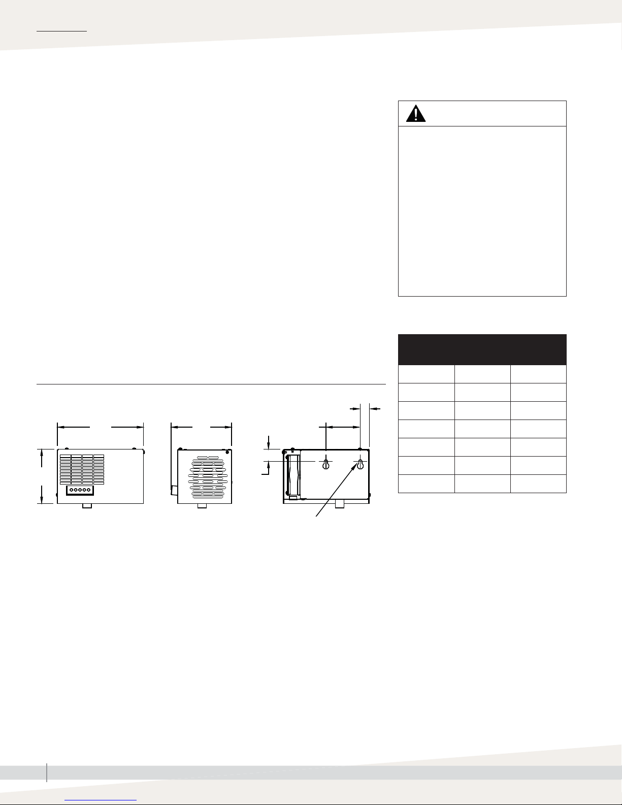
FIGURE 26-1: XTR STEAM BLOWER DIMENSIONS
Front view Side view Back view
A
C
E
F
WARNING
Standing water in XTR steam blower
Make sure the XTR steam blower is
installed plumb. If not installed plumb,
standing water can accumulate, which
can:
• Cause bacteria and mold growth,
which can cause illness;
• Affect steam blower performance;
• Cause 212 °F (100 °C) water to
discharge from the steam blower,
which can cause severe personal
injury.
Table 26-1:
XTR steam blower dimensions
Dimension inches mm
A 10 254
B 6-1/4 159
C 7 178
B
OM-7726
mc_050712_1418
D
1/4" (6.4 mm) dia holes
D 1-3/8 35
E 4 102
F125
mc_050712_1417
XTR INSTALLATION, OPERATION, AND MAINTENANCE MANUAL
26
Page 31
INSTALLATION
Dispersion:
XTR fan pack
XTR fan packs are designed for use in fi nished spaces. They disperse steam
into large open spaces and are useful where there are no air-handling ducts.
On a call for humidity the XTR humidifi er produces steam and provides power
to the XTR fan pack. The fan pack distributes the steam to the room. When
the call for humidity ends and the humidifi er stops producing steam, the fan
pack operates for another two minutes to distribute the remaining steam before
deactivating.
Due to condensation inside the hose or tubing, the output of the fan pack
depends on the length of the steam hose or tube connecting it to the humidifi er.
When the humidifi er is wired to 120V, the fan pack will deliver 5.6 lbs/
hr (2.5 kg/h) of steam with up to 24" (610 mm) of steam hose or insulated
tubing. Each additional 24" of hose or tubing will reduce steam output by
approximately 0.3 lbs/hr (0.1 kg/h).
DISTANCE FROM HUMIDIFIER TO XTR FAN PACK
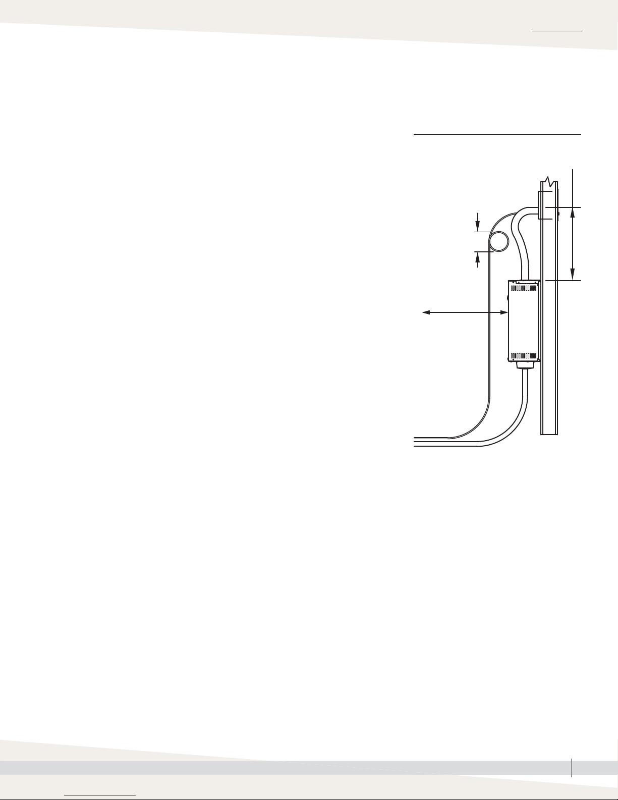
The XTR fan pack must be mounted near the XTR humidifi er to minimize the
steam hose length. If the fan pack is mounted directly above the humidifi er,
16" (406 mm) of clearance is required for the steam hose to make the bend
without kinking, as shown in Figure 23-1.
FIGURE 27-1: XTR FAN PACK
AND HUMIDIFIER RECOMMENDED
DIMENSIONS AND CLEARANCES
16" (406 mm)
Important:
Loop condensate drain
hose below fan pack
(to provide trap, which
prevents steam from
escaping into drain)
6" (150 mm)
30" (760 mm)
for service access
minimum for steam
hose bend
• See the XTR fan pack dimensions in Figure 24-1.
• See the piping connection notes in Figure 11-2.
The maximum recommended length of steam hose is 6' (1.8 m). Longer runs of
steam hose or tubing result in more condensation.
Note: If 6' (1.8 m) of steam hose does not reach from the humidifi er to the fan
pack, extend the run to a maximum of 20' (6 m) with copper tubing as
shown in Figure 24-2. Insulate the tubing with 1" (25 mm) of fi berglass
to minimize loss of capacity and effi ciency.
Note: See Figure 25-1 for fan pack clearance
recommendations in the humidifi ed space.
mc_050712_1439
90-1551-clearance
XTR INSTALLATION, OPERATION, AND MAINTENANCE MANUAL
27
Page 32
INSTALLATION
Dispersion: XTR fan pack
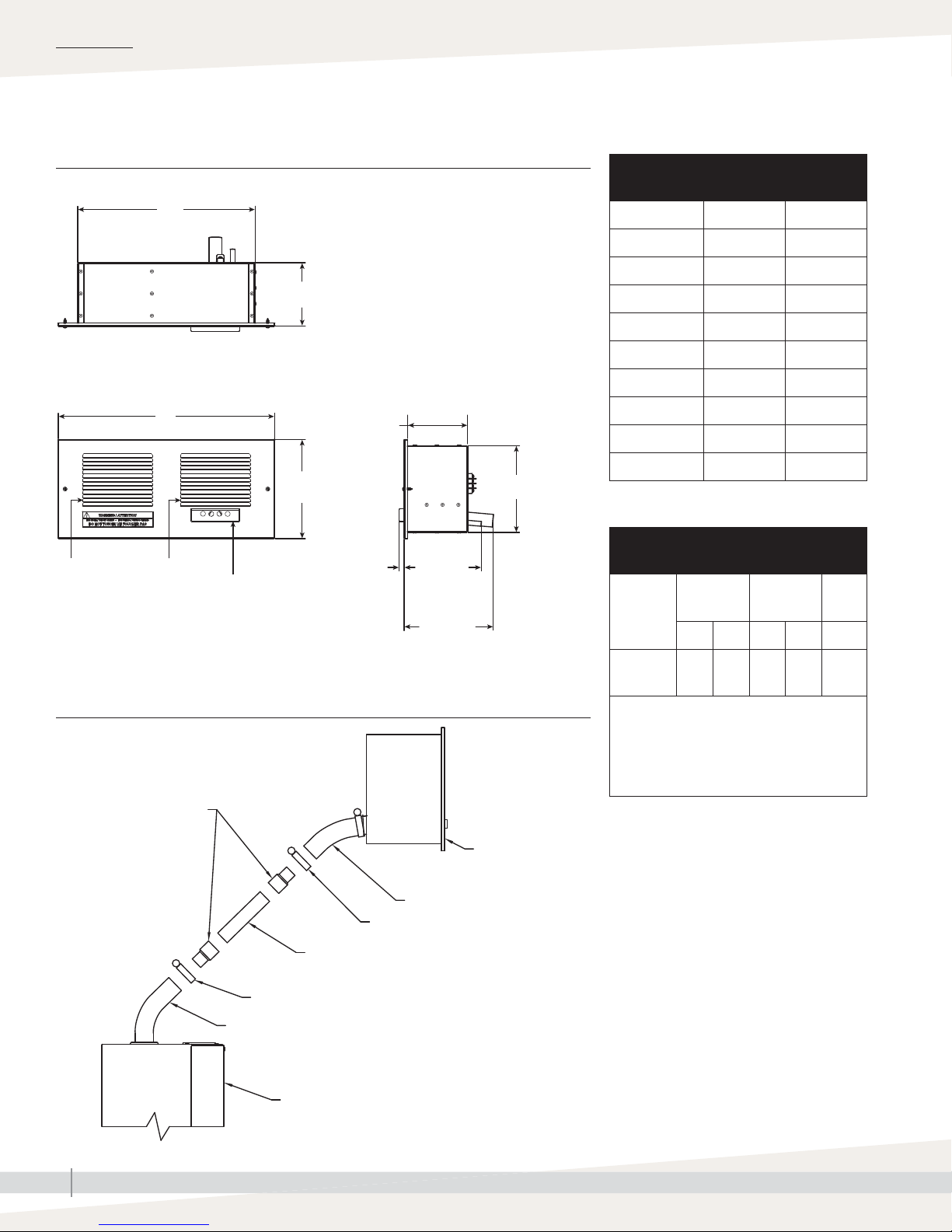
FIGURE 28-1: XTR FAN PACK DIMENSIONS
Top
A
B
Front
C
D
Fan inlet Fan outlet
Steam dispersion
manifold
90-1554
mc_050712_1441
Table 28-1:
XTR fan pack dimensions
Dimension inches mm
A 14 356
B 5 127
C 17-1/16 433
D 7-13/16 198
E 4-3/4 121
Side
E
F
F 6-7/8 175
G 3/8 10
H 6-1/16 154
I 7-1/16 179
mc_050712_1443
Table 28-2:
G
H
I
XTR fan pack specifications
Fan pack
model
Shipping
weight
lbs kg lbs kg dBA*
Operating
weight
Sound*
FIGURE 28-2:
EXTENDING DISTANCE FROM HUMIDIFIER TO FAN PACK WITH COPPER TUBE
1" x 3/4" (DN25 x DN20)
reducer couplings
Fan pack
Steam hose
1½" (DN40) hose clamp
1" (DN25) copper tube, 20' (6
m) maximum run length
1½" (DN40) hose clamp
Steam hose
90-1565a
mc_050712_1442
XTR humidifi er
SDU-003F 10.4 4.7 8.4 3.8 < 38
Notes:
* Sound measurement taken 6.5' (2 m) in
front of steam blower cabinet.
• Input voltage: 24 VAC, supplied by XTR
humidifi er.
• Fan pack ships separately from humidifi er.
mc_050712_1444
XTR INSTALLATION, OPERATION, AND MAINTENANCE MANUAL
28
Page 33
INSTALLATION
Dispersion: XTR fan pack
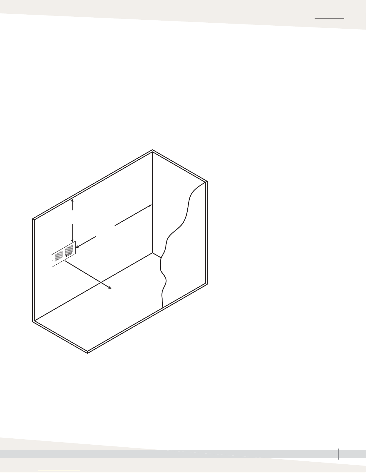
MINIMUM CLEARANCES IN THE HUMIDIFIED SPACE
Air movement due to drafts or as a result of temperature stratifi cation may cause uneven distribution of humidity within
the conditioned space. To ensure even distribution, install the fan pack in a central location.
To prevent condensation on surfaces and furnishings, install the fan pack so the steam being discharged has enough
room to be absorbed into the air before encountering surfaces. See Figure 29-1.
FIGURE 29-1: XTR FAN PACK RECOMMENDED MINIMUM CLEARANCES IN HUMIDIFIED SPACE
Distances provided are recommended minimums. These
guidelines are for a 120V installation with fan pack
discharging into a space with 70 °F (21 °C) air temperature
and 30% RH.
18" (457 mm)
minimum from ceiling
90-1552
mc_050712_1440
24" (610 mm)
minimum to right
and left wall
48" (1220 mm)
minimum unobstructed
space to objects in
front of grille
• If XTR humidifi er operates on 208V or higher, allow
12" (305 mm) additional space between grille and any
obstruction or surface.
• If room temperature is less that 70 °F (21 °C), allow an
additional 6" (150 mm) to each distance for every 2 °F
(1.1 °C) drop in temperature.
• If RH set point is higher than 45%, allow an additional 12"
(305 mm) of space between grille and any obstruction or
surface.
• Warmer room air temperature and RH below 30% will
reduce the amount of unobstructed space required to
absorb discharged steam.
XTR INSTALLATION, OPERATION, AND MAINTENANCE MANUAL
29
Page 34
INSTALLATION
Dispersion: XTR fan pack
MOUNTING
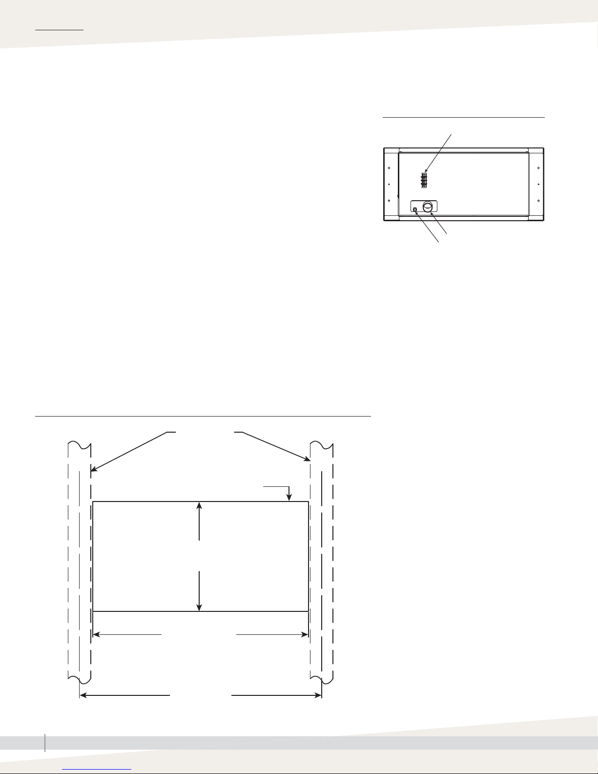
The XTR fan pack installs between the studs of a standard 16"-on-center wall.
Drywall on both sides of the wall must be removed for piping and wiring. To
ensure proper operation, the fan pack must be mounted level. See Figure 26-2.
1. Use the four 1-1/2" mounting screws (provided with fan pack) to attach
fan pack housing to wall studs.
2. Connect steam hose to fan pack, and secure with hose clamp (steam hose
and clamp are provided with humidifier). See Figure 26-1.
Note: If more than 6' (1.8 m) of steam hose is required, see Figure 28-2.
3. Connect 3/8" ID condensate tubing to fan pack, and secure with wire-tie.
4. To create a seal, make a 6" (150 mm) loop in the condensate hose, as
shown in Figure 30-1. Loop must be located below fan pack condensate
connection. Use wire to secure loop, and do not kink condensate hose.
Loop is required to prevent steam from escaping into drain.
5. Use the two 5/8" screws (provided with fan pack) to attach grille to
fan housing and drywall. If painting grille is desired, see a painting
professional for acceptable paint products for high-temperature (212 °F
[100 °C]), high-humidity environments.
FIGURE 30-1:
XTR FAN PACK CONNECTIONS
Electrical terminals (see Figure 27-1)
90-1560X
Steam hose connection
Condensate drain hose connection
Note: Back of fan pack shown
mc_050912_1136
FIGURE 30-2: WALL OPENING DIMENSIONS
Wall studs
Cut-out opening in wall
7-1/4"
(184 mm)
14-1/4" (362 mm)
90-1550
mc_050912_1135
16” (406 mm)
XTR INSTALLATION, OPERATION, AND MAINTENANCE MANUAL
30
Page 35

Dispersion: XTR fan pack
WIRING
See Figure 14-1.
1. Mount humidistat in area to be humidified according
to installation instructions included with control. Install
humidistat in same room or area as fan pack, but at
least 10' (3 m) from fan pack.
2. Wire humidistat to humidifier using standard 24V
thermostat wire.
3. Disconnect all power to humidifier before wiring fan
pack terminals to humidifier terminals labeled FAN
PACK. Use standard 24V thermostat wire.
INSTALLATION
XTR INSTALLATION, OPERATION, AND MAINTENANCE MANUAL
31
Page 36

OPERATION
Principle of operation
The XTR humidifi er delivers humidity in the form of steam to the conditioned
space via a dispersion tube in the HVAC system duct, or an optional XTR steam
blower or XTR fan pack.
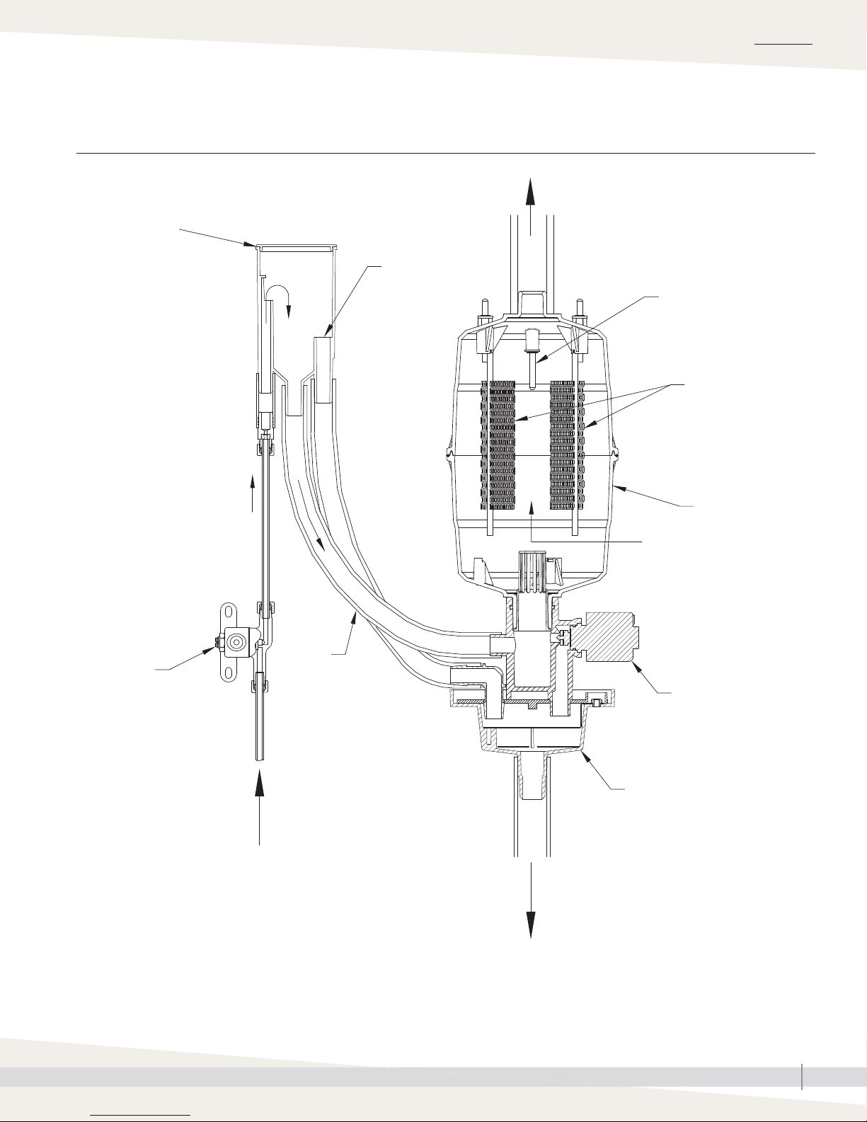
The humidifi er generates steam by energizing two electrodes that extend into
the water in the replaceable steam cylinder. Current fl owing between the
electrodes causes the water to boil, creating steam. See Figure 29-1.
Water is introduced to the humidifi er through a fi ll valve to a fi ll cup located in
the top of the cabinet. The fi ll cup serves as an overfl ow reservoir and provides
an air gap between the humidifi er and the water source.
The steam cylinder is fi lled from the bottom; it is seated in a drain cup
assembly which includes a drain valve.
The drain valve and fi ll valve work together to
• maintain the water level in the cylinder;
• deliver the rated steam capacity, based on the electrical conductivity of the
water; and
• temper the drain water.
Steam is delivered into the airstream through a dispersion tube mounted in
the HVAC system ductwork. Openings in the dispersion tube are fi tted with
tubelets that extend into the center of the tube. The design of the dispersion
tube and tubelets distribute steam over a wide area in the duct and direct any
condensed moisture back into the steam hose.
Start-up time
The time needed for the XTR electrode
humidifi er to reach rated capacity depends on
input voltage to the humidifi er and the electrical
conductivity of the supply water.
Input voltage
The humidifi er can be installed to operate using
120, 208, 230, or 240 volts. The higher the
voltage, the higher the nominal steam capacity.
See Table 5-1.
A system operating at 120 volts will take longer
to reach capacity than a system operating at
240 volts.
Supply water conductivity
The humidifi er should be plumbed to cold water
with conductivity from 125 to 1250 μS/cm.
Hard water, which has a high mineral content,
and softened water generally have higher
conductivity than naturally soft water.
Systems plumbed to high-conductivity water will
reach capacity sooner than systems plumbed
to low-conductivity water. As the humidifi er
operates, minerals build up in the cylinder,
which increases the conductivity of the water.
With a new cylinder, allowing the humidifi er to
operate continuously will allow it to reach rated
capacity in the shortest amount of time.
When the humidifi er controller detects humidity below the set point, and the
humidifi er is turned on:
1. Internal controller in humidifier energizes electrodes and measures current
in water between electrodes.
2. Controller adjusts water level in cylinder via fill valve and drain valve to
maintain constant current.
Note: During operation, water level in cylinder depends on conductivity of
water (which is determined by mineral content of water).
XTR INSTALLATION, OPERATION, AND MAINTENANCE MANUAL
32
Page 37
Principle of operation
FIGURE 33-1: XTR HUMIDIFIER PRINCIPLE OF OPERATION
Fill cup
Overfl ow
OPERATION
Steam outlet
High water sensor
Electrodes
Fill valve
Steam cylinder
Electrical resistance in
fi ll water
Fill line
Drain valve
90-1522
Drain cup
Supply water
Drain
XTR INSTALLATION, OPERATION, AND MAINTENANCE MANUAL
33
Page 38
OPERATION
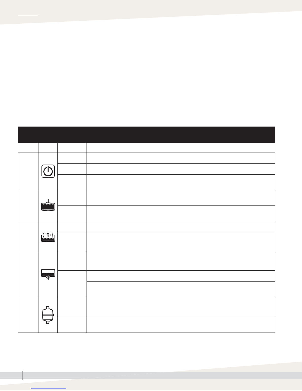
Control panel
Green lights indicate normal operation.
Yellow Steam light indicates humidifi er is operating at less than rated capacity.
Yellow Steam light also indicates humidifi er is in Test mode.
Flashing red Service light indicates cylinder has reached the end of its life and
needs to be replaced.
Solid red lights indicate humidifi er has shut down and requires service.
Disconnecting power to humidifi er resets internal timers.
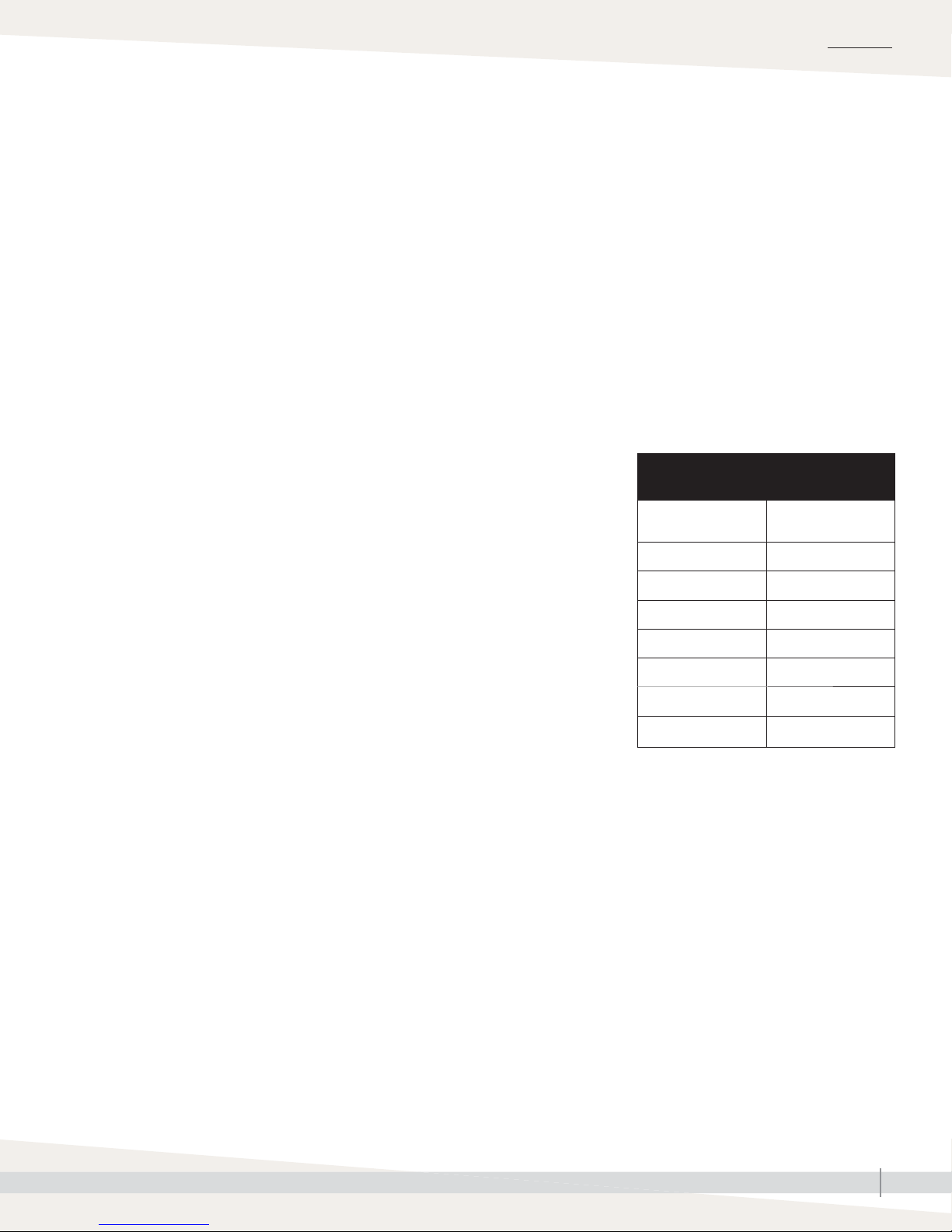
Table 34-1:
XTR humidifier control panel
Function Symbol Light Description
Off Humidifi er is turned off or is not receiving power.
On-off
button
Solid green Humidifi er is turned on.
Flashing green
Humidifi er is preparing to turn on. Occurs if power is disconnected, then restored with switch ON. Flashes
for one minute.
Safety functions
XTR humidifi ers are protected against running
dry. Current does not fl ow if the electrodes in
the steam cylinder are not submerged in water.
Fill
Steam
Drain
Service
Solid green
Solid red
Solid green Normal operation. Humidistat is calling for steam, and humidifi er is operating.
Solid yellow
Flashing green
Solid green
Flashing red
Solid red
Normal operation. Fill valve is energized allowing water to fl ow into cylinder via fi ll cup. Does not illuminate
when tempering water during drain cycle.
Fault mode. Indicates cylinder needs water but cannot fi ll. Humidifi er shuts down. Occurs if high water sensor
does not detect water after fi ll valve is energized for 40 minutes.
Humidifi er is operating but is not delivering steam at rated capacity. Occurs if humidifi er has operated
for 168 hours at less than rated capacity due to low water conductivity. Light will turn green once water
conductivity increases and humidifi er is producing steam at rated capacity.
Humidifi er is preparing to drain. Fill valve is open to temper water in cylinder. Occurs when humidifi er is
turned off and during forced drain down (168 hours of operation with no drain activity.)
Drain valve is energized and open, draining cylinder. Valve remains energized for four minutes.
Indicates end-of-season shutdown. Occurs if humidifi er does not receive call for humidity for 72 hours. Light
remains on for 24 hours.
Cylinder has reached the end of its life and needs to be replaced. Occurs after humidifi er has operated for
at least 168 hours and for an additional 24 hours at a current level below 75% of the maximum operating
current. Humidifi er continues to operate, but at reduced capacity.
Operational problem with humidifi er. Humidifi er shuts down. Occurs when unit detects over-current which can
be caused by failure to drain or other system failures. Contact DriSteem for assistance.
XTR INSTALLATION, OPERATION, AND MAINTENANCE MANUAL
34
Page 39
Control panel
OPERATION
During initial start up with a new cylinder, the humidifi er may run through a
series of drain and fi ll cycles until the conductivity of the water is in a range
that allows normal operation. During this time, the Steam light illuminates
green. If the humidifi er cannot produce steam at the rated level after trying
for 168 hours, the Steam light illuminates yellow. The humidifi er continues to
operate in this state until the rated output is reached.
The conductivity of naturally soft water, hard water, and softened water
changes as the water heats up, but the internal controller adjusts the water
level to maintain a nominal current between the electrodes. Over the life of
the cylinder, minerals that build up on the electrodes will reduce their effective
surface area and affect the resistance between them. The operating water level
will increase with use until it reaches the high water sensor. At that point, the
Service light will fl ash red indicating that the cylinder needs to be replaced.
The humidifi er will continue to operate but with reduced output.
Any time power is disconnected or the humidifi er is turned off, the internal
timer for start-up and drain cycles is reset.
If the humidifi er has operated 168 hours without a drain cycle, the drain valve
will open to drain the cylinder. Normal operation will continue.
Note: When automatic drain water tempering is activated, the fi ll valve opens
to introduce cold water into the cylinder when the humidifi er begins a
drain cycle. This is to prevent hot water from entering the drain. The
drain valve remains open for four minutes to allow all water to drain
from the cylinder. See “ Activating automatic drain water tempering” on
Page 9.
If the humidifi er is operating and a power failure occurs, once power is
restored, the On-off light will fl ash green for one minute, then the humidifi er will
turn on.
END-OF-SEASON DRAIN
If the humidifi er does not receive a call for humidity for 72 hours, the humidifi er
controller will drain the cylinder, and the Drain light will remain on for 24
hours if there is no call for humidity. The humidifi er will resume normal
operation when there is a call for humidity.
Outdoor temperature and indoor RH
It is important to adjust the RH setting
according to Table 35-1 to avoid excessive
condensation when outdoor temperature is low.
For example, with an outdoor temperature of
20 °F (-7 ºC) the correct setting will be 35%.
If the temperature is expected to fall to 0 °F
(-18 ºC) that evening, reduce the setting to 25%
several hours prior to the temperature change.
These settings represent a balance between
humidity levels that would be most desirable for
comfort and humidity levels that are suitable for
avoiding condensation on windows.
Table 35-1:
Outdoor temperature and indoor RH
Outdoor
temperature
40 ºF (-4 ºC) 45%
30 ºF (-1 ºC) 40%
20 ºF (-7 ºC) 35%
10 ºF (-12 ºC) 30%
0 ºF (-18 ºC) 25%
-10 ºF (-23 ºC) 20%
-20 ºF (-29 ºC) 15%
Keeping humidity in
Be sure to keep fi replace dampers closed when
not in use. They provide an escape route for
heat, as well as humidity.
Dissipating excessive humidity
On occasion, indoor moisture-producing
activities such as clothes drying, cooking,
showers, etc., may raise the humidity level
higher than it should be, even though the
humidifi er is not operating. Telltale indications
are condensation or frost on cold surfaces
such as windows, doors, or walls. If such
condensation persists for several hours, the
home or building should be ventilated to
dissipate the potentially damaging excess
moisture.
Recommended
indoor RH
XTR INSTALLATION, OPERATION, AND MAINTENANCE MANUAL
35
Page 40

OPERATION
Start-up
START-UP CHECKLIST
☐ Read this manual and other information sent with your humidifi er.
☐ Verify that fi eld wiring is done per instructions in this manual and per unit
wiring diagram.
☐ Do not use demineralized, deionized, or reverse-osmosis water.
☐ Confi rm that proper grounding and approved earth ground are provided.
☐ Confi rm that water fi ll line was thoroughly fl ushed before it was connected
to humidifi er.
☐ Turn water supply on, and confi rm that drain valve is closed.
If the force of air exiting water supply lines blows fi ll cup cap off during fi rst
fi ll cycle, this is not a sign of defect or a cause for concern; simply replace
fi ll cup cap after all air has exited water line.
☐ Confi rm that airfl ow proving switch (if installed) is closed.
WARNING
Electric shock hazard
Only qualifi ed electrical personnel
should perform start-up.
Contact with energized circuits can
cause property damage, severe
personal injury or death as a result of
electrical shock or fi re.
Make sure cabinet front and side
covers are installed before turning on
electrical power.
☐ Confi rm that high limit humidistat (if installed) is closed.
☐ Turn power on, and confi rm that humidifi er control panel lights are
illuminated.
☐ If you experience diffi culties, see “Troubleshooting” on Page 40
☐ Verify that humidifi er, controls, piping, electrical connections, steam supply,
and dispersion device are installed according to the following:
• Installation instructions in this manual
• Ladder style wiring diagram (inside of humidifi er side cover) and
external connections wiring diagram (on humidifi er subpanel)
• Governing codes
☐ Make sure cylinder is fully seated into drain valve, and verify that all
electrical connections are secure before applying power.
☐ Make sure cabinet front and side covers are in place and secure.
☐ Verify that humidifi er is mounted level and securely supported before fi lling
with water. See operating weights in Table 5-2.
☐ Verify that humidifi er is level from front to back and side to side after it is full
of water.
XTR INSTALLATION, OPERATION, AND MAINTENANCE MANUAL
36
Page 41

Start-up
START-UP PROCEDURE
The control for your humidifi er (purchased separately) mounts either in the
return air duct or on a wall in the humidifi ed room. If a blower or fan pack is
installed, a call for humidity will turn on the indoor unit blower. After the XTR
humidifi er and control are installed and connected properly:
1. Perform all applicable “Start-up checklist” items at left.
2. Set control to the maximum RH setting.
3. Make sure water saddle valve is open and humidifier is on.
4. After Fill light turns off, perform cleaning procedure as follows:
a. Operate humidifi er long enough for steam to be produced.
b. Press On-off button to begin draining cylinder. You might hear fi ll valve
open to allow cold water to fl ow into cylinder to cool drain water. Drain
light fl ashes for several minutes while cylinder drains.
c. Press On-off button to turn humidifi er on, and repeat Steps a and b.
OPERATION
WARNING
Hot surface and steam hazard
Dispersion device, steam hose, and
tubing can contain steam, and surfaces
can be hot. Discharged steam is not
visible.
To avoid burns, do not to touch
dispersion tube, front of steam blower,
or front of fan pack, and do not put any
part of body in front of steam outlets.
Avoid contact with hot surfaces and air
into which steam has been discharged.
mc_043012_0920
5. Once humidifier operation is verified, reduce setting to recommended
inside RH (see Table 31-1).
Note: If your humidifi er control has a test mode, do not leave in test mode,
or humidifi er will not operate.
6. Monitor humidifier operation through multiple drain and fill cycles. Verify
that there are no leaks in steam hose and (if using fan pack) condensate
hose connections.
XTR INSTALLATION, OPERATION, AND MAINTENANCE MANUAL
37
Page 42
MAINTENANCE
Steam cylinder
BEFORE PERFORMING SERVICE OR MAINTENANCE PROCEDURES ON THE
HUMIDIFIER, FOLLOW THE SHUTDOWN PROCEDURE.
Each month during the humidifi cation season, inspect the steam cylinder,
fi ll and drain valves, steam hose, condensate piping, water supply piping,
drain, drain piping, and all other parts for proper operation and/or cleaning
requirements. Verify proper operation of high limit humidistat, relays, and
airfl ow proving switch.
Steam cylinder service life depends on operating hours and water hardness.
Replace the steam cylinder when fl ashing red Service light indicates cylinder
has reached the end of its life and needs to be replaced — after extended run
time.
To replace the steam cylinder:
1. Follow shutdown procedure.
2. Remove front cover.
3. Pull three wires off posts on top of cylinder. (Two large electrode
conductors and one water level probe conductor.)
4. Loosen hose clamp at top of cylinder.
5. Slide hose off top of cylinder.
WARNING
Shutdown procedure
To prevent severe personal injury or
death from electrical shock, follow this
shutdown procedure before performing
service or maintenance procedures on
this humidifi er (after cylinder is drained
and cooled):
1. Press On-off switch to turn humidifi er
off. Humidifi er will begin to drain.
2. Allow humidifi er to drain (humidifi er
will drain for four minutes).
3. When the green Drain light turns
off, shut off all electrical power to
humidifi er using fi eld-installed fused
disconnect, and lock all power
disconnect switches in OFF position.
4. Close fi eld-installed manual water
supply shut-off valve.
6. Slide cylinder up and out of drain assembly. Discard cylinder.
7. Remove O-ring from groove in drain assembly using small screw driver.
8. Inspect drain assembly and remove any debris.
9. Insert new O-ring into groove in drain assembly. (O-ring is provided with
cylinder.) Dampen O-ring with water before inserting canister. Do not use
oil, grease, or any lubricant besides water.
10. Make sure strainer is inserted into bottom of new cylinder.
11. Insert cylinder into drain assembly. Position cylinder with label facing out.
12. Slip steam hose over top of cylinder, and tighten hose clamp.
13. Reattach three wires to posts on top of cylinder. (Larger electrode
conductors are interchangeable.)
14. Replace front cover.
15. Restore electrical power to humidifier.
16. Turn humidifier on and verify green On-off light is illuminated.
17. Each time cylinder is replaced, ensure fan in steam blower or fan pack is
operating during a call for humidification, and ensure steam outlet is not
blocked.
18. See Start-up procedure on Page 32 if necessary.
WARNING
Hot water
Cylinder and any undrained water may
be hot. To avoid injury from hot water,
follow the shutdown procedure above,
and allow the humidifi er to cool down
before proceeding with maintenance.
Note:
DriSteem recommends keeping a spare steam
cylinder in stock during the humidifi cation
season. See “Replacement parts" on Page 41.
XTR INSTALLATION, OPERATION, AND MAINTENANCE MANUAL
38
Page 43
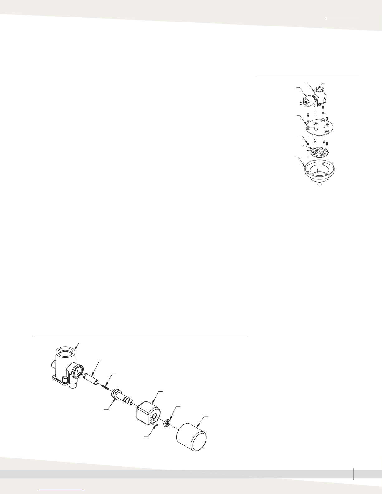
Drain valve
MAINTENANCE
If either of the following issues occur after several months of runtime, follow the
drain valve maintenance procedures below. See Figure 39-2.
• Drain valve is closed, but draining and fi lling continue.
• End of cylinder life prompt appears prematurely.
1. When steam cylinder is empty, turn humidifier off. Place all power
disconnects in OFF position, and lock in OFF position.
2. Remove cabinet front and side covers and steam cylinder (see Page 34).
3. Vacuum loose scale and debris out of the drain valve port.
4. Disconnect quick connect from 24 VAC drain valve coil.
5. Slide cap (A) off of drain valve coil (C).
6. Turn hex nut (B) counter-clockwise. Loctite on nut will cause drain valve
coil assembly to turn out of drain valve body (G). Remove coil/actuator
assembly from drain valve body. Make sure spring (E) and plunger (F) do
not fall out of actuator (D).
7. Clean plunger (F), spring (E), actuator (D), and plastic drain valve body
(G) with clean water.
8. Reassemble drain valve.
Note: When threading actuator (D) into drain valve body (G), make sure
it is not cross threaded. Torque actuator into drain valve body to 18
in-lb (2.0 N·m).
9. Connect drain valve coil quick connect, and slide cap (A) onto drain valve
coil (C).
10. See “Start-up procedure” on Page 32 if returning humidifier to operation.
Note: If this procedure does not resolve valve issues, perform the drain
valve assembly maintenance procedure in Figure 39-1.
FIGURE 39-2: DRAIN VALVE BODY MAINTENANCE
Drain valve body (G)
Plunger (F)
Spring (E)
Drain valve coil (C)
FIGURE 39-1: DRAIN VALVE ASSEMBLY
MAINTENANCE
Drain valve body
Drain valve coil
Drain cup plate
Insert
Ground plate
Drain cup
Perform the following procedure only if the
procedure at left does not resolve drain valve
issues.
1. Perform Steps 1 through 4 at left.
2. Remove the three screws and washers
securing drain cup plate to drain cup.
3. Lift drain valve body/plate assembly off of
drain cup.
4. Vacuum loose scale and debris out of drain
cup.
5. Remove ground plate, and clean scale and
debris from ground plate and outlet of drain
valve body.
6. Reassemble drain valve assembly: Fit
mounting screws with washers, insert them
through drain cup plate, and tighten them
into drain cup.
Note:
Pay close attention to all parts shown above.
Verify that:
• Ground plate is in groove of drain cup.
• Insert is in place through ground plate
loop.
Failure to get ground plate and insert solidly
connected to frame will compromise ground
safety circuit.
7. Clean end of hose, and reconnect it to drain
valve body with hose clamp.
8. Plug Molex plug into its mating wire harness
plug.
O-ring
OM-7630
Actuator (D)
Torque to 18 in-lb (2.0 N·m)
Wires to quick connect
Nut (B)
OM-7631
Cap (A)
XTR INSTALLATION, OPERATION, AND MAINTENANCE MANUAL
39
Page 44

MAINTENANCE
Troubleshooting
The troubleshooting guide (Table 42-1) and the test procedure below are
intended to help diagnose and resolve general operational problems with the
XTR humidifi er.
If a problem persists, call DriSteem Technical Support. See inset at left.
TEST MODE
To check general function of humidifi er and components, the following Test
Mode procedure can be performed. Humidifi er must be powered, and control
must be turned to OFF position. The humidifi er should be plumbed to a water
supply and the drain line should be connected. Test Mode involves repeatedly
pressing the On-off button and listening for audible clicks as the various
components are energized and de-energized. The humidifi er will remain in
Test Mode for fi ve minutes, then automatically return to the Off state. If the
procedure is not completed in fi ve minutes, restart Test Mode. If the humidifi er
or components do not respond as indicated, investigate components being
tested.
1. Press On-off button, and hold it for 10 seconds until all control panel lights
turn on. On-off, Fill, Steam, and Drain lights will illuminate green. Service
light will illuminate red.
2. Press On-off button again. All control panel lights will turn off.
3. Press On-off button again. Fill light will illuminate red, and Steam light will
illuminate yellow.
4. Press On-off button again. Red Fill light will turn off. Steam light will remain
yellow.
WARNING
Electric shock hazard
Contact with electrical circuits can
cause property damage, personal
injury or death. Service and
troubleshooting must be performed by
qualifi ed electrician.
DriSteem Technical Support
Have the following information ready when
calling Technical Support. See phone number
inside front cover of this manual.
Humidifi er model number
_______________________________
Humidifi er serial number
_______________________________
When issue began
_______________________________
_______________________________
5. Press On-off button again. Listen for audible click as power relay is
energized. If click is not heard replace control circuit board.
6. Press On-off button again. Listen for audible click as power relay is
de-energized. If click is not heard, replace control circuit board.
7. Press On-off button again. Listen for a click as fill valve is energized.
Water should flow, filling the cylinder. If valve does not energize. measure
voltage across the CON1 FILL terminals on control circuit board. If 24
VAC is present, replace fill valve. If 24 VAC is not present, replace control
circuit board.
XTR INSTALLATION, OPERATION, AND MAINTENANCE MANUAL
40
_______________________________
Issue description
_______________________________
_______________________________
_______________________________
Continued
Page 45

Troubleshooting
TEST MODE (CONTINUED)
8. Press On-off button again. Listen for click as fill valve is de-energized.
Water should stop flowing. If valve remains energized, check for voltage
across CON! FILL terminals on control circuit board. If less than 1 VAC is
present, replace fill valve. If more than 1 VAC is present, replace control
circuit board.
9. Press On-off button again. Listen for a click as the drain valve is energized.
Water should flow down the drain. If the valve does not energize, remove
the drain valve wires from terminals J5 and J6 on the control circuit board
and measure voltage across the terminals. If 24 VAC is present, replace
drain valve. If 24 VAC is not present, replace control circuit board.
10. Press On-off button again. Listen for click as drain valve is de-energized.
Water should stop flowing down the drain. If valve remains energized,
remove the drain valve wires from terminals J5 and J6 on the control
circuit board and measure voltage across the terminals. If less than 1 VAC
is present, replace drain valve. If more than 1 VAC is present, replace
control circuit board.
MAINTENANCE
11. Press On-off button again. Listen for a faint click as the FAN PACK
terminals on the control circuit board are energized. If the terminals do not
energize, (24 VAC measured across P10 terminals) replace the control
circuit board.
12. Press On-off button again. Listen for click as FAN PACK terminals are
de-energized. If the terminals fail to energize (more than 1 VAC measured
across terminals) replace control circuit board.
Exit Test Mode by disconnecting power to humidifi er or allowing fi ve minutes to
elapse.
XTR INSTALLATION, OPERATION, AND MAINTENANCE MANUAL
41
Page 46
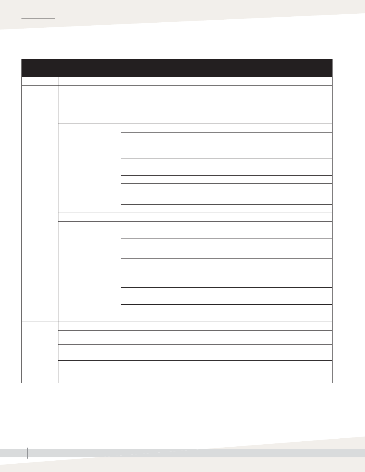
MAINTENANCE
Troubleshooting
Table 42-1:
XTR humidifier troubleshooting guide
Problem Possible cause Action
Check L1, N/L2 and Ground connections.
Check HUMIDISTAT and FAN PACK Terminal connections.
General
operating
problems.
Humidifi er will
not turn on or
turn off.
Steam light does
not turn on.
Water leaking
from humidifi er.
Water constantly
runs down drain.
Field-wired terminal
connections
Internal connections
No power to humidifi er
Humidifi er not turned on Make sure front cover is attached to engage safety interlock switch. Press On-off button.
No power to 24 volt control
circuit
Call for humidity not being
received
Loose plumbing connections
Malfunctioning drain valve Check valve function using Test Mode.
Debris in drain valve
preventing it from closing
O-ring in drain valve is not
properly seated in groove
Water is fl owing from fi ll cup
overfl ow port
HUMIDISTAT terminals must be connected to an on/off or modulating device. Control circuit board
will be damaged if 24 volts are connected to HUMIDISTAT terminals.
Check wiring connections and settings on accessory items such as high limit switch and airfl ow
proving switch.
Check electrode and high water probe connections on the top of the cylinder.
Check to make sure two sets of blue/white wire jumpers from control circuit board to current sensing
circuit board are secure and have the proper polarity. Blue wire on jumper set towards front of
humidifi er should be on top on both plugs. Blue wire on jumper set towards back of humidifi er should
be on bottom of both plugs.
Make sure ribbon cable from membrane switch is securely plugged into control circuit board.
Check that terminals from internal components are securely attached to proper tabs on circuit boards.
Make sure one of the electrode wires extends through toroid ring on current sensing circuit board.
Make sure Black/white wire from L1 is attached to terminal that matches input voltage.
Check main power supply and switch.
Check for proper voltage across L1 and N/L2 terminals.
Make sure ribbon cable from membrane switch is securely plugged into control circuit board.
Check reset switch on transformer.
With humidifi er energized, check for 24± 6 volts AC across J2 & J5 terminals. If okay, check for 5
Volts DC across +5V and GND test points on control circuit board. If okay, replace membrane switch.
If not, replace control circuit board.
If 5 volts DC are not present between +5V and GND test points, remove blue/white wire jumpers
and check DC voltage across +5V and GRD points. If 5 Volts DC are present, replace current sensing
circuit board. If 5 volts DC are not present, replace control circuit board.
Check control wiring and setting.
Check wiring and settings of high RH limit switch and airfl ow proving switch, if installed.
Check water supply connection at fi ll valve inlet. Tighten as needed.
Check internal hose clamp connections. Reposition clamps and tighten as needed.
Check steam hose connection on top of cylinder. Tighten clamp as needed.
Remove cylinder and clean debris from drain valve.
Remove cylinder and reposition O-ring.
Check internal hoses and remove kinks or blockage.
Disassemble brass fi tting in feed line between inlet valve and fi ll cup. Make sure small rubber fl ow
orifi ce is in place in brass fi tting.
Continued
XTR INSTALLATION, OPERATION, AND MAINTENANCE MANUAL
42
Page 47
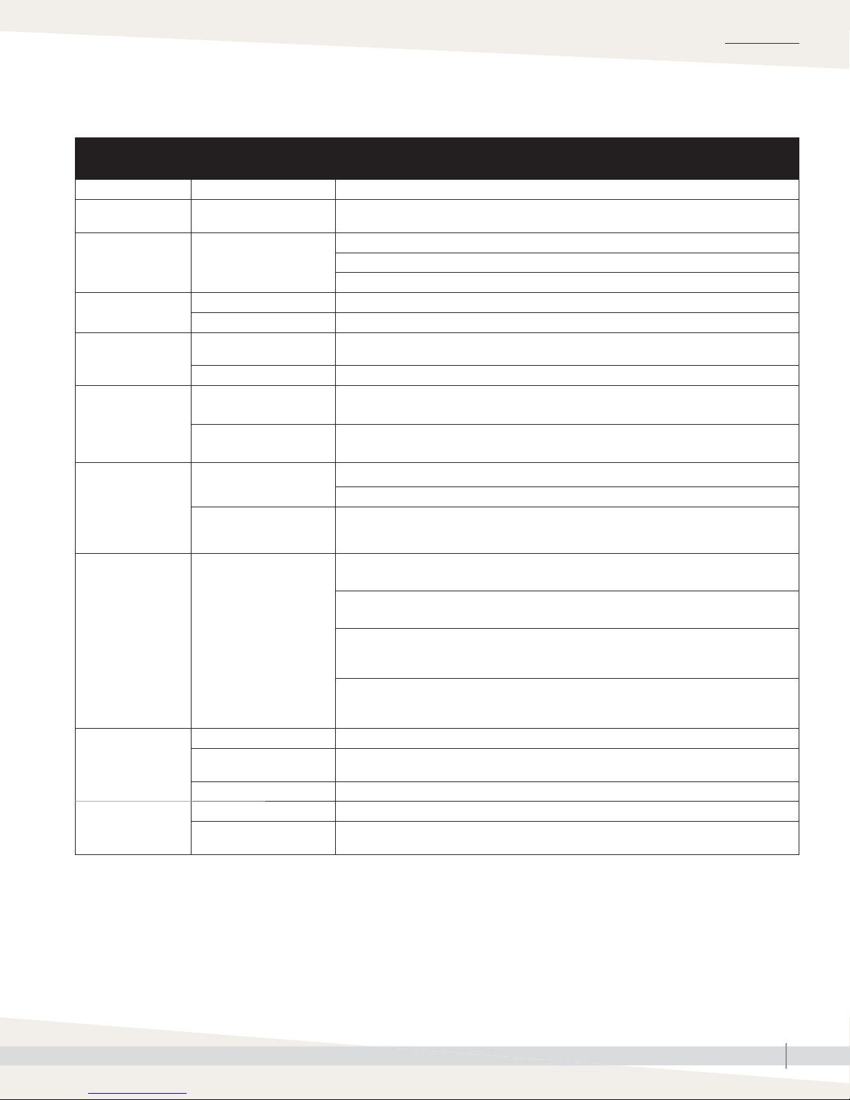
Troubleshooting
Table 42-1:
XTR humidifier troubleshooting guide (continued)
Problem Possible cause Action
Humidifi er makes
gurgling sound.
Fill valve makes
banging sound.
Humidifi er will not fi ll.
Humidifi er will not
drain.
Water in duct from
dispersion tube.
Excess condensation in
steam hose
Water hammer from line
pressure
Saddle valve not open Open saddle valve.
Malfunctioning fi ll valve Check valve function using Test Mode.
Debris in drain valve
blocking outlet port
Malfunctioning drain valve Check valve function using Test Mode.
Dispersion tube installed
incorrectly
Impurities in steam hose or
tubing causing foaming
Make sure steam hose has constant downward slope to humidifi er or to tees and traps in low
spots of hose.
Make sure water supply line does not contact ductwork.
Install shock arrestor.
Install section of 1/4" braided fi ll line. Conform to local codes.
Remove cylinder and clean debris from drain valve.
Install dispersion tube with tubelets facing straight up.
Rinse cylinder and hose in clean water.
MAINTENANCE
Service light fl ashing
red before end of
humidifi cation season.
Yellow Steam light.
Humidifi er is not
satisfying demand.
Excess humidity.
Cylinder full of mineral
deposits
Humidifi er runs in short
cycles (does not reach
capacity)
Humidifi er operating below
rated capacity.
Notes:
• Normal for systems
plumbed to lowconductivity water and
systems that operate for
short cycles.
• Recommended fi ll water
conductivity is 125 to
1250 μS/cm.
Control setting is too low Adjust control to higher setting.
Control mounted in wrong
location
Short run times Use blower activation relay, or run constant HVAC fan.
Control setting is too high Adjust control to lower setting.
Control mounted in wrong
location
Plumb humidifi er to fi ltered water.
Plumb humidifi er to softened water.
Use blower activation relay, or run constant HVAC fan.
Plumb humidifi er to softened water.
Use blower activation relay, or run constant HVAC fan.
To determine operating current, attach clamp-on ammeter to one of the electrode wires on top
of cylinder.
Add add 1/4 to 1/2 tab sodium bicarbonate (i.e., Alka Seltzer) to water in cylinder increase
water conductivity. Consult DriSteem for further advice.
See Installation Instructions with control for correct mounting location.
See Installation Instructions with control for correct mounting location.
Continued
XTR INSTALLATION, OPERATION, AND MAINTENANCE MANUAL
43
Page 48
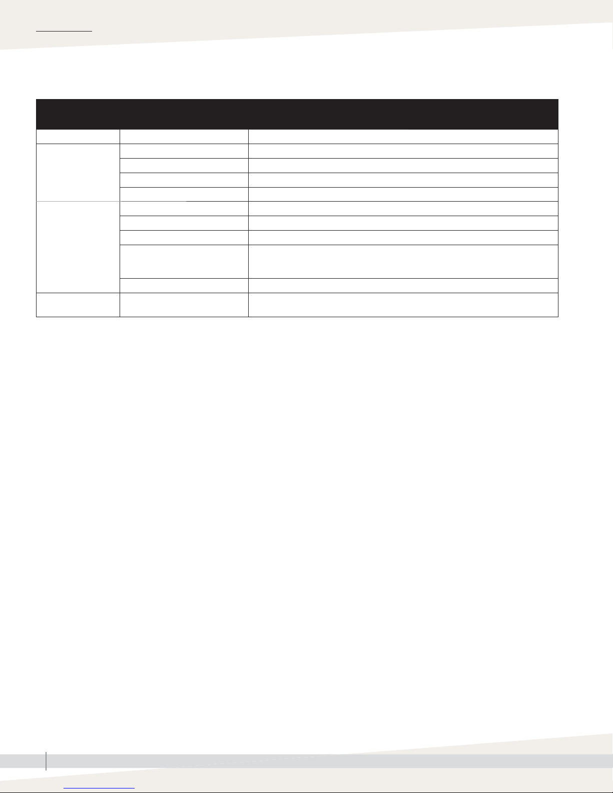
MAINTENANCE
Troubleshooting
Table 42-1:
XTR humidifier troubleshooting guide (continued)
Problem Possible cause Action
Tubing connection Check all connections.
Water dripping from
fan pack or steam
blower
Fan pack or steam
blower fan does not
operate
Fan noise in fan pack
or steam blower
Fan not operating See “Fan does not operate” in Problem column below.
Steam outlet blocked Clean steam dispersion manifold outlet.
Foaming in cylinder or steam hose Rinse components with clean water.
Wiring Check wiring.
XTR humidifi er power Check that humidifi er is powered and on.
No call for humidity Adjust humidistat setting. Check location of humidistat.
During a call for humidity, confi rm 24 VAC output from humidifi er terminals for steam
Circuit board output
Motor failure Replace fan motor.
Obstructed or damaged fan Clear and clear obstructions, or replace fan motor.
blower or fan pack. See steam blower wiring on Page 22. See fan pack wiring on Page
27.
XTR INSTALLATION, OPERATION, AND MAINTENANCE MANUAL
44
Page 49
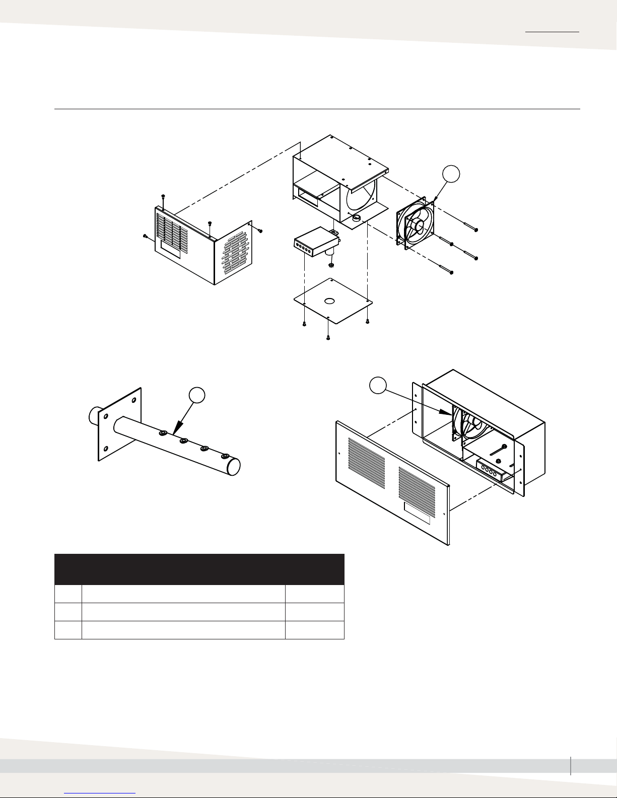
MAINTENANCE
Replacement parts:
FIGURE 45-1: REPLACEMENT PARTS, XTR DISPERSION
XTR dispersion tube XTR fan pack SDU-003F
Dispersion devices
XTR steam blower SDU-003E
OM-7727
1
OM-7511
2
Table 45-1:
Replacement parts, XTR dispersion
Item Description Part No.
1 Fan, SDU-003E steam blower and SDU-003F fan pack 407109-004
2 XTR dispersion tube, with screws 162728-001
1
OM-7728
XTR INSTALLATION, OPERATION, AND MAINTENANCE MANUAL
45
Page 50
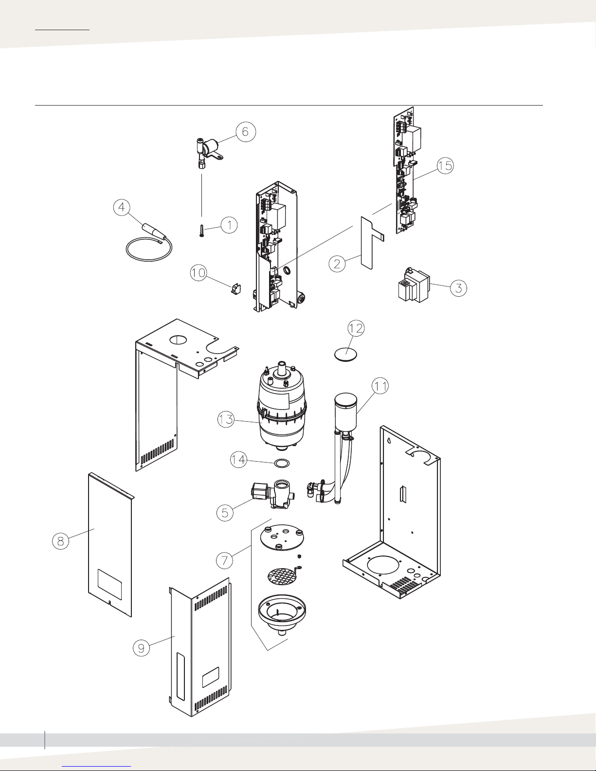
MAINTENANCE
Replacement parts:
FIGURE 46-1: XTR HUMIDIFIER REPLACEMENT PARTS
XTR humidifier
XTR INSTALLATION, OPERATION, AND MAINTENANCE MANUAL
46
OM-7803
Page 51
Replacement parts: XTR humidifi er
MAINTENANCE
Table 47-1:
XTR humidifier replacement parts
Item Description Part No.
1 Strainer, in-line, fi ll valve 300051-100
2 Switch, membrane 408638-001
3 Transformer 408965-003
4 Wire, electrode 531008-101
5 Valve, drain 405900-003
6 Inlet valve, supply water 505096-100
7 Drain cup assembly 194610-101
8 Cover front, with screw 531013-401
9 Cover, side, with screws 531013-402
10 Switch, safety interlock 530010-103
11 Fill cup, with hoses 531004-002
12 Cap, fi ll cup 530010-064
Kit, cylinder, XTR, XT-5/10, XT-002/003,
13
120-277V, IP
14 O-Ring, cylinder 530001-044
194601-001
Table 47-2:
Accessories
Description Part No.
XTR fan pack (see Figure 41-1) SDU-003F
XTR steam blower (see Figure 41-1) SDU-003E
XTR dispersion tube (see Figure 41-1) 162728-001
Relay, blower activation 530010-153
Switch, airfl ow proving (electric) 406190
Switch, airfl ow proving, sail 406192
Switch, limit, high humidity 4594
Pump, condensate, rated for 160 °F (65 °C) 400283
Hose, steam, 6' (1.8 m), with clamps 305400-100
Hose, drain, 10' (3 m), with clamps 530005-010
Humidistat, duct, on-off 405842-030
Humidistat, room, on-off 405842-035
Humidistat, duct, modulating 405875
Humidistat, room, modulating 405840
15 Control board
XTR INSTALLATION, OPERATION, AND MAINTENANCE MANUAL
47
Page 52

W
ARRANTY
Expect quality from the industry leader
For more than 45 years, DriSteem has been
leading the industry with creative and reliable
humidifi cation solutions. Our focus on quality is
evident in the construction of the XTR humidifi er.
DriSteem also leads the industry with a Twoyear Limited Warranty and optional extended
warranty.
For more information
www.dristeem.com
[email protected]
For the most recent product information
visit our Web site: www.dristeem.com
DRI-STEEM Corporation
An ISO 9001:2000 certifi ed company
U.S. Headquarters:
14949 Technology Drive
Eden Prairie, MN 55344
800-328-4447 or 952-949-2415
952-229-3200 (fax)
Two-year Limited Warranty
DriSteem Corporation (“DriSteem”) warrants to the original user that its products will be free from
defects in materials and workmanship for a period of two (2) years after installation or twentyseven (27) months from the date DriSteem ships such product, whichever date is the earlier.
If any DriSteem product is found to be defective in material or workmanship during the applicable
warranty period, DriSteem’s entire liability, and the purchaser’s sole and exclusive remedy, shall
be the repair or replacement of the defective product, or the refund of the purchase price, at
DriSteem’s election. DriSteem shall not be liable for any costs or expenses, whether direct or
indirect, associated with the installation, removal or reinstallation of any defective product. The
Limited Warranty does not include cylinder replacement for electrode steam humidifi ers.
DriSteem’s Limited Warranty shall not be effective or actionable unless there is compliance with
all installation and operating instructions furnished by DriSteem, or if the products have been
modifi ed or altered without the written consent of DriSteem, or if such products have been subject
to accident, misuse, mishandling, tampering, negligence or improper maintenance. Any warranty
claim must be submitted to DriSteem in writing within the stated warranty period. Defective parts
may be required to be returned to DriSteem.
DriSteem’s Limited Warranty is made in lieu of, and DriSteem disclaims all other warranties,
whether express or implied, including but not limited to any IMPLIED WARRANTY OF
MERCHANTABILITY, ANY IMPLIED WARRANTY OF FITNESS FOR A PARTICULAR PURPOSE, any
implied warranty arising out of a course of dealing or of performance, custom or usage of trade.
DriSteem SHALL NOT, UNDER ANY CIRCUMSTANCES BE LIABLE FOR ANY DIRECT, INDIRECT,
INCIDENTAL, SPECIAL OR CONSEQUENTIAL DAMAGES (INCLUDING, BUT NOT LIMITED
TO, LOSS OF PROFITS, REVENUE OR BUSINESS) OR DAMAGE OR INJURY TO PERSONS OR
PROPERTY IN ANY WAY RELATED TO THE MANUFACTURE OR THE USE OF ITS PRODUCTS. The
exclusion applies regardless of whether such damages are sought based on breach of warranty,
breach of contract, negligence, strict liability in tort, or any other legal theory, even if DriSteem has
notice of the possibility of such damages.
By purchasing DriSteem’s products, the purchaser agrees to the terms and conditions of this Limited
Warranty.
European offi ce:
Marc Briers
Grote Hellekensstraat 54 b
B-3520 Zonhoven
Belgium
+3211823595 (voice)
+3211817948 (fax)
E-mail: [email protected]
Continuous product improvement is a policy of
DriSteem Corporation; therefore, product
features and specifi cations are subject to
change without notice.
DriSteem is a registered trademark of Research
Products Corporation and is fi led for trademark
registration in Canada and the European
community.
Product and corporate names used in this
document may be trademarks or registered
trademarks. They are used for explanation only
without intent to infringe.
© 2015 Research Products Corporation
Extended warranty
The original user may extend the term of the DriSteem Limited Warranty for a limited number of
months past the initial applicable warranty period and term provided in the fi rst paragraph of this
Limited Warranty. All the terms and conditions of the Limited Warranty during the initial applicable
warranty period and term shall apply during any extended term. An extended warranty term of
an additional twelve (12) months or twenty four (24) months of coverage may be purchased. The
extended warranty term may be purchased until eighteen (18) months after the product is shipped,
after which time no extended warranties are available.
Any extension of the Limited Warranty under this program must be in writing, signed by DriSteem,
and paid for in full by the purchaser.
mc_051308_0630
Form No. XTR-IOM-EN-0515
Part No. 10010628 B2206355A
 Loading...