

DriSteem XT Series, XTP 002, XTP 003, XTP 006, XTP 010 Installation, Operation And Maintenance Manual
...
READ AND SAVE THESE INSTRUCTIONS
XT SERIES
Electrode Steam Humidifiers
Installation, Operation,
and Maintenance Manual
Warnings and cautions
WARNINGS AND CAUTIONS
WARNING
Indicates a hazardous situation that could result in death or
serious injury if instructions are not followed.
CAUTION
Indicates a hazardous situation that could result in damage to or
destruction of property if instructions are not followed.
WARNING
Attention installer
Read this manual before installing, and leave this manual with product owner. This product must be installed by qualifi ed
HVAC and electrical contractors. Installation must be code approved. Improper installation can cause property damage,
severe personal injury, or death as a result of electric shock, burns, or fi re.
DriSteem
Europe: +3211823595
Read all warnings and instructions
Read this manual before performing service or maintenance procedures on any part of the system. Failure to follow all
warnings and instructions could produce the hazardous situations described, resulting in property damage, personal injury,
or death.
Failure to follow the instructions in this manual can cause moisture to accumulate, which can cause bacteria and mold
growth or dripping water into building spaces. Dripping water can cause property damage; bacteria and mold growth can
cause illness.
Hot surfaces and hot water
This steam humidifi cation system has extremely hot surfaces. Water in steam cylinders, steam tubing, and dispersion
assemblies can be as hot as 212 °F (100 °C). Discharged steam is not visible. Contact with hot surfaces, discharged hot
water, or air into which steam has been discharged can cause severe personal injury. To avoid severe burns, follow the
cool-down procedure in this manual before performing service or maintenance procedures on any part of the system.
®
Technical Support: North America: 800-328-4447
Disconnect electrical power
Disconnect electrical power before installing supply wiring or performing service or maintenance procedures on any part of
the humidifi cation system. Failure to disconnect electrical power could result in fi re, electrical shock, and other hazardous
conditions. These hazardous conditions could cause property damage, personal injury, or death.
Contact with energized circuits can cause property damage, severe personal injury, or death as a result of electrical shock
or fi re. Do not remove cabinet doors until electrical power is disconnected.
Follow the shutdown procedure on Page 49 before performing service or maintenance procedures on any part of the
system.
XT SERIES INSTALLATION, OPERATION, AND MAINTENANCE MANUAL
ii
Warnings and cautions
WARNING
Electrical shock hazard
If the humidifi er starts up responding to a call for humidity during maintenance, severe personal injury or death from
electrical shock could occur. To prevent such start-up, follow the shutdown procedure on Page 49.
CAUTION
Follow steam piping recommendations
Controlling condensate fl ow and collection in an XT Series humidifi er system is critical to maximize performance. Failure to follow
the steam piping recommendations in this manual can cause system pressure fl uctuations and increase cylinder pressure, steam
velocity, and condensate noise.
Hot discharge water
Discharge water can be as hot as 212 °F (100 °C) and can damage some drain plumbing materials not rated for hot drain
water. To prevent such damage, make sure drain water tempering is selected, and supply water is not heated. Do not shut off
supply water to the cylinder before it is drained.
Excessive supply water pressure
Supply water pressure greater than 80 psi (550 kPa) can cause the humidifi er to overfl ow.
XT SERIES INSTALLATION, OPERATION, AND MAINTENANCE MANUAL
iii

Table of contents
ATTENTION INSTALLER
Original Instructions
Read this manual before installing. Leave
manual with product owner.
DriSteem Technical Support
800-328-4447
Website:
Documents can be viewed, printed or ordered
from our website, www.dristeem.com.
DriCalc sizing and selection software:
®
DriCalc
is our humidifi cation system sizing
and selection software, which can be accessed
from dristeem.com.
WARNINGS AND CAUTIONS . . . . . . . . . . . . . . . . . . . . . . . . . . . . . . . . . . . . . . . . . . . . . . . . . . . ii
PRODUCT OVERVIEW . . . . . . . . . . . . . . . . . . . . . . . . . . . . . . . . . . . . . . . . . . . . . . . . . . . . . . . .2
Capacities, line currents, and fusing . . . . . . . . . . . . . . . . . . . . . . . . . . . 4
Dimensional drawings . . . . . . . . . . . . . . . . . . . . . . . . . . . . . . . . . . . . . 5
Dimensions and weights . . . . . . . . . . . . . . . . . . . . . . . . . . . . . . . . . . . 6
Dispersion options . . . . . . . . . . . . . . . . . . . . . . . . . . . . . . . . . . . . . . . 7
INSTALLATION . . . . . . . . . . . . . . . . . . . . . . . . . . . . . . . . . . . . . . . . . . . . . . . . . . . . . . . . . . . . . .8
Selecting a location . . . . . . . . . . . . . . . . . . . . . . . . . . . . . . . . . . . . . . 8
Mounting . . . . . . . . . . . . . . . . . . . . . . . . . . . . . . . . . . . . . . . . . . . . . . 9
Fill cup extension kit . . . . . . . . . . . . . . . . . . . . . . . . . . . . . . . . . . . . . 11
Steam cylinder . . . . . . . . . . . . . . . . . . . . . . . . . . . . . . . . . . . . . . . . . 12
Piping: . . . . . . . . . . . . . . . . . . . . . . . . . . . . . . . . . . . . . . . . . . . . . . . 13
Supply water and drain . . . . . . . . . . . . . . . . . . . . . . . . . . . . . . . . 13
Field piping overview. . . . . . . . . . . . . . . . . . . . . . . . . . . . . . . . . . 14
XT steam blowers. . . . . . . . . . . . . . . . . . . . . . . . . . . . . . . . . . . . . 15
Humidifier wiring. . . . . . . . . . . . . . . . . . . . . . . . . . . . . . . . . . . . . . . . 17
Sensor placement . . . . . . . . . . . . . . . . . . . . . . . . . . . . . . . . . . . . . . . 19
Dispersion: . . . . . . . . . . . . . . . . . . . . . . . . . . . . . . . . . . . . . . . . . . . . 20
Selecting the dispersion assembly location . . . . . . . . . . . . . . . . . . . 20
Returning condensate to steam cylinder . . . . . . . . . . . . . . . . . . . . . 22
Steam outlet connections . . . . . . . . . . . . . . . . . . . . . . . . . . . . . . . 23
Steam outlet connections with hose . . . . . . . . . . . . . . . . . . . . . . . . 24
Single dispersion tube . . . . . . . . . . . . . . . . . . . . . . . . . . . . . . . . . 28
Drip tee installation . . . . . . . . . . . . . . . . . . . . . . . . . . . . . . . . . . . 31
Connecting to humidifier with tubing . . . . . . . . . . . . . . . . . . . . . . . 32
Rapid-sorb . . . . . . . . . . . . . . . . . . . . . . . . . . . . . . . . . . . . . . . . . 33
XT steam blowers. . . . . . . . . . . . . . . . . . . . . . . . . . . . . . . . . . . . . 40
Principle of operation . . . . . . . . . . . . . . . . . . . . . . . . . . . . . . . . . . . . 45
XT SERIES INSTALLATION, OPERATION, AND MAINTENANCE MANUAL
iv

Table of contents
OPERATION . . . . . . . . . . . . . . . . . . . . . . . . . . . . . . . . . . . . . . . . . . . . . . . . . . . . . . . . . . . . . . 45
Start-up checklist . . . . . . . . . . . . . . . . . . . . . . . . . . . . . . . . . . . . . . . . 47
Model XTP . . . . . . . . . . . . . . . . . . . . . . . . . . . . . . . . . . . . . . . . . . . . 48
Shutdown and cool-down procedures . . . . . . . . . . . . . . . . . . . . . . . . . 49
MAINTENANCE . . . . . . . . . . . . . . . . . . . . . . . . . . . . . . . . . . . . . . . . . . . . . . . . . . . . . . . . . . . 49
Replacing steam cylinder . . . . . . . . . . . . . . . . . . . . . . . . . . . . . . . . . . 50
Drain valve . . . . . . . . . . . . . . . . . . . . . . . . . . . . . . . . . . . . . . . . . . . . 51
Troubleshooting . . . . . . . . . . . . . . . . . . . . . . . . . . . . . . . . . . . . . . . . 52
Replacement parts . . . . . . . . . . . . . . . . . . . . . . . . . . . . . . . . . . . . . . . 56
Accessories . . . . . . . . . . . . . . . . . . . . . . . . . . . . . . . . . . . . . . . . . . . . 61
WARRANTY . . . . . . . . . . . . . . . . . . . . . . . . . . . . . . . . . . . . . . . . . . . . . . . . . . . . . . . . . . . . . . 64
XT SERIES INSTALLATION, OPERATION, AND MAINTENANCE MANUAL
1
Product overview
PRODUCT OVERVIEW
DriSteem XT Series electrode steam humidifi ers use heat caused by electrical
resistance in their fi ll water to boil the fi ll water into humidifi cation steam.
Steam output and water conductivity are managed via automatic draining and
fi lling. See Figure 2-1.
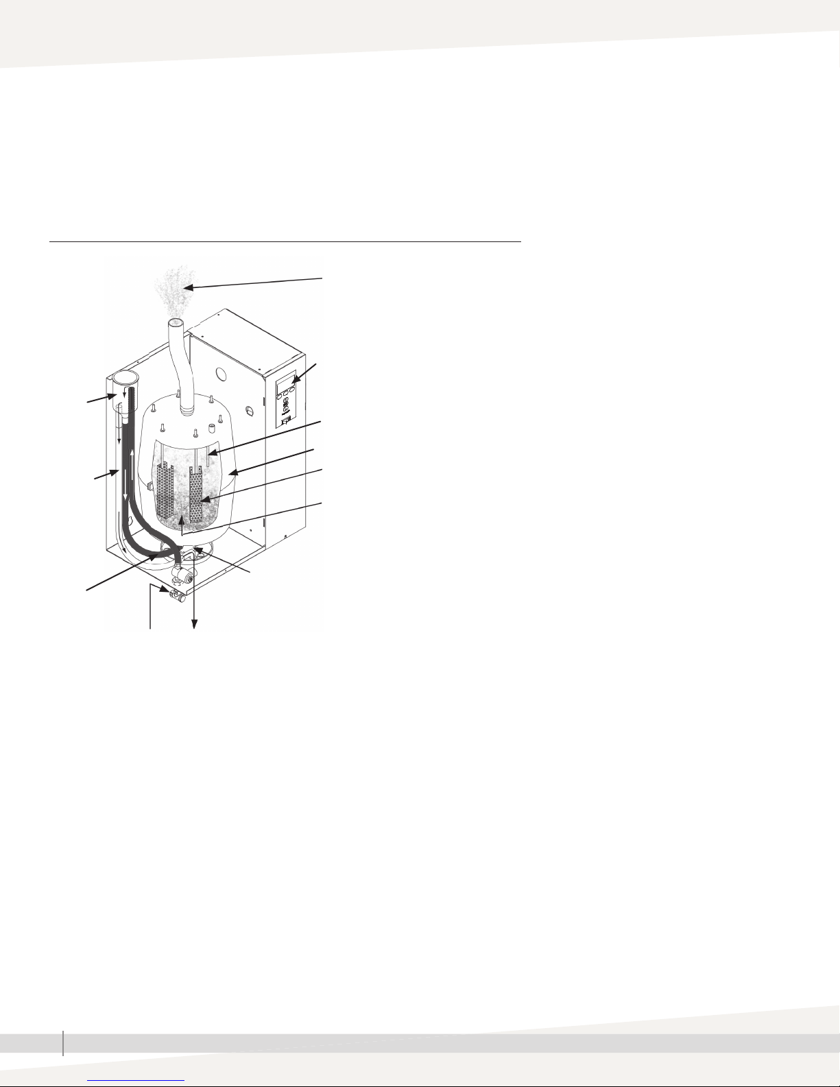
FIGURE 2-1: XT SERIES HUMIDIFIER COMPONENTS
Steam to duct or XT steam blower
(see dispersion options on Page 8)
Control panel for on-board controller
(see Figure 3-1)
Fill cup
High water sensor
Steam cylinder
Overfl ow
hose
Electrodes
Electrical resistance in fi ll water
OM-7661_aa
Download DriSteem literature
DriSteem product manuals can be
downloaded, printed, and ordered from our
website: www.dristeem.com
The Vapor-logic Installation and Operation
Manual ships with Model XTP humidifi ers.
It is a comprehensive manual. Refer to it
for information about the keypad/display
and Web interface, and for troubleshooting
information.
Cylinder drain
Fill hose
Supply water connection
Note: See detailed installation drawing on Page 14 and principle of operation on Page 45.
Overfl ow to drain
XT SERIES INSTALLATION, OPERATION, AND MAINTENANCE MANUAL
2
Product overview
SUPPLY WATER
There are benefi ts and trade-offs to consider when the application allows a
choice between hard and softened water:
Hard water: The benefi t of hard water is less frequent draining and fi lling
than with softened water, which results in better energy and water effi ciency
and more consistent steam output. However, cylinder replacement could
be more frequent with hard water, because hard water scale coats the
electrodes. The harder the water, the more frequent the need for a new
cylinder.
Softened water may be used in the XT series electrode humidifi er. However,
softened water ions stay in solution to much higher concentrations than
hard water ions. The result can be more frequent draining and fi lling, which
results in less energy and water effi ciency, and less consistent steam output.
While softened water can reduce scale build-up in the cylinder, it can also
shorten cylinder electrode life.
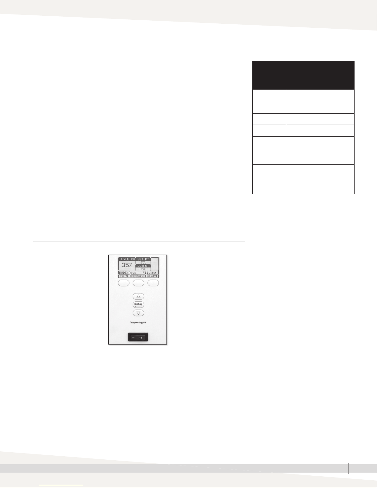
CONTROLLER
The Model XTP humidifi er Vapor-logic® controller features menus for all
humidifi er functions, with a Web interface for access to all functions via
Ethernet. See "Operations" beginning on page 45 for details.
FIGURE 3-1: XT SERIES HUMIDIFIER CONTROL PANEL
Table 3-1:
DriSteem supply water guidelines for
XT series electrode humidifiers
Supply water
conductivity
Chlorides Not limited
pH 6.5 to 8.5
Silica < 15 ppm
Demineralized, deionized, and reverseosmosis water cannot be used.
Supply water outside of these guidelines may
void your DriSteem warranty. Please contact
your DriSteem Representative or DriSteem
Technical Support if you need advice.
350 to 1250 μS/cm (roughly
comparable to water hardness
of 10 to 36 grains per gallon).
XTP Vapor-logic keypad/display
Status display and
menu selection
Softkeys for direct
menu access
Navigation buttons
for item selection
Controller on-off switch*
* On-off switch for control board — not a safety shut-off to humidifi er power wiring.
XT SERIES INSTALLATION, OPERATION, AND MAINTENANCE MANUAL
3

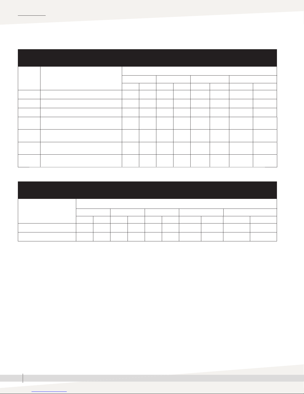
SPECIFICATIONS
Capacities, line currents, and fusing
Table 4-1:
Line currents and recommended fusing for XT Series humidifiers
Model Nominal steam capacity
XTP lbs/hr kg/h
002 5 2 1.7 1
003 10 5 3.3
006 18 8 6.0
010 30 14 10.0 3
017 50 22 16.5 3
025 75 34 25.0 3
033 100 45 33.3 3
042 125 57 41.7 3
048 143 65 47.8 3
050* 150 68 50.0 3
067* 198 90 66.7 3
083* 250 113 83.3 3
096* 287 130 95.7 3
* These models have two steam cylinders and require independent service connections.
kW Phase Volts Maximum line current (amps) Recommended fusing (amps)
120 17 25
208 10 15
230 8 15
240 8 15
208 19 25
230 17 25
1
3
1
3
240 17 25
277 14 20
400 10 13
480 8 15
600 7 10
208 11 15
240 10 15
400 6 10
480 5 10
600 4 10
208 35 45
230 31 40
240 30 40
277 26 35
400 18 25
480 15 20
600 12 15
208 20 25
240 17 25
400 10 13
480 9 15
600 7 10
208 33 45
240 29 40
400 17 25
480 14 20
600 12 15
208 55 70
240 48 60
400 29 40
480 24 35
600 19 25
400 43 63
480 36 50
600 29 40
400 58 80
480 48 70
600 39 50
400 72 100
480 60 80
600 48 70
400 80 100
480 69 90
600 55 70
400 2 x 43 2 x 63
480 2 x 36 2 x 50
600 2 x 29 2 x 40
400 2 x 58 2 x 80
480 2 x 48 2 x 70
600 2 x 39 2 x 50
400 2 x 72 2 x 100
480 2 x 60 2 x 80
600 2 x 48 2 x 70
400 2 x 80 2 x 100
480 2 x 69 2 x 90
600 2 x 55 2 x 70
XT SERIES INSTALLATION, OPERATION, AND MAINTENANCE MANUAL
4
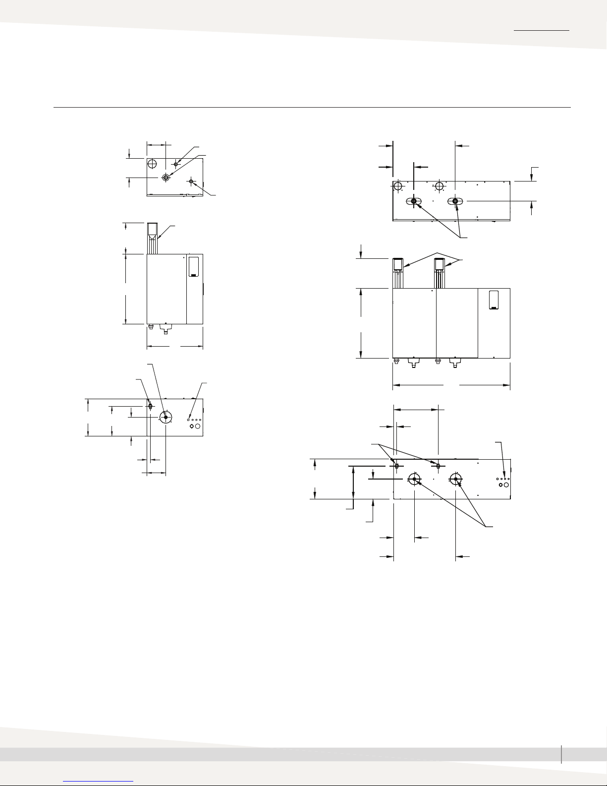
Dimensional drawings
FIGURE 5-1: XT SERIES HUMIDIFIER DIMENSIONAL DRAWINGS
SPECIFICATIONS
Top
Front
Bottom
Models XTP 002 through 048
E
Electrical knockout
D
Fill cup extension kit*
10.0 (254)
B
A
Drain outlet
Supply water
connection
C
F
D
G
E
Dispersion outlet
Electrical knockout
Electrical
knockouts
OM-7672
Top
Front
10.0 (254)
B
Bottom
Supply water connections
C
Models XTP 050 through 096
21.0 (533)
E
Dispersion outlets
Fill cup extension kits*
A
15.1 (384)
G
Electrical
knockouts
D
Notes:
* Fill cup extension (Figure 5-1) is required for the following:
- All XT Series humidifi ers using Ultra-sorb or Rapid-sorb
- When developed length of steam tubing is more than 20' (6 m)
and duct static pressure exceeds 2" wc (498 Pa)
• Labeled dimensions: inches (millimeters).
• See mounting dimensions in Figure 9-1.
OM-7673
F
D
E
21.0 (533)
XT SERIES INSTALLATION, OPERATION, AND MAINTENANCE MANUAL
Drain outlets
5
SPECIFICATIONS
Dimensions and weights
Table 6-1:
XT Series humidifier dimensions by model number
Model XTP
Dimension Description
A Cabinet width 14.6 370 17.7 450 19.9 504 39.6 1005
B Cabinet height 20.6 523 24.1 612 25.6 650 25.6 650
C Cabinet depth 8.7 221 11.8 300 13.4 340 13.4 340
Cabinet back edge to steam/drain outlet
D
centers
E Cabinet left edge to steam/drain outlet centers 4.4 112 6.0 152 7.0 178 7.0 178
Cabinet back edge to supply water connection
F
center
Cabinet left edge to supply water connection
G
center
002, 003, 006 010, 017 025, 033, 042, 048 050, 067, 083, 096
inches mm inches mm inches mm inches mm
4.5 114 6.0 152 6.7 170 6.7 170
6.7 170 9.5 241 11.1 282 11.1 282
1.0 25 1.0 25 1.1 28 1.1 28
Table 6-2:
XT Series humidifier weights by model number
Model XTP
002, 003 006 010, 017 025, 033, 042, 048 050, 067, 083, 096
lbs kg lbs kg lbs kg lbs kg lbs kg
Shipping weight 37 17 37 17 50 23 64 29 139 63
Maximum operating weight 38 17 46 21 79 36 115 52 219 99
XT SERIES INSTALLATION, OPERATION, AND MAINTENANCE MANUAL
6
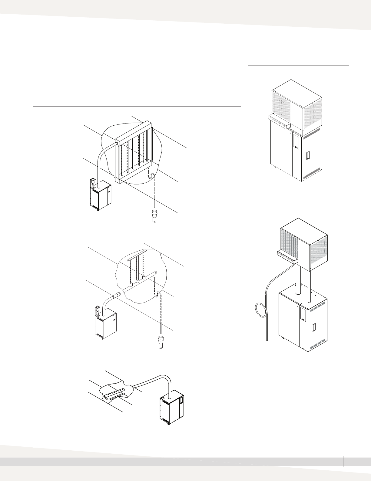
Dispersion options
SPECIFICATIONS
The duct dispersion options in Figure 7-1 and the open space dispersion
options in Figure 7-2 are available for XT Series humidifi ers. For
installation details, see “Dispersion” beginning on Page 20.
FIGURE 7-1: XT SERIES HUMIDIFIER DUCT DISPERSION OPTIONS
Ultra-sorb
OM-7667
FIGURE 7-2: XT STEAM BLOWERS
Mounted on top of humidifi er
OM-7670
Mounted up to 10' (3 m) away from
humidifi er
Rapid-sorb
Single dispersion tube
OM-7668
OM-7698
OM-7669
Notes:
• Models XTP 010 and larger require condensate drain. See Page 32.
• XT steam blowers (SDU) shipped with fuses to be installed in connected XT series humidifi ers.
XT SERIES INSTALLATION, OPERATION, AND MAINTENANCE MANUAL
7
INSTALLATION
Selecting a location
HUMIDIFIER
When selecting a location for the humidifi er, consider the following:
• Proximity to the duct
Install the humidifi er near the air duct system where the dispersion assembly
will be located. The maximum recommended length for steam hose
connecting a single humidifi er to a dispersion assembly is 10' (3 m). The
maximum recommended developed length for tubing connecting a single
humidifi er to a dispersion assembly is 20' (6 m).
For more information about installing dispersion assemblies, see
“Dispersion” beginning on Page 20.
• Elevation of the installed dispersion assembly
The recommended installation location for the dispersion assembly is at an
elevation higher than the humidifi er. However, if the dispersion assembly
must be installed at an elevation lower than the humidifi er, install a drip tee
and drain. See “Drip tee installation” on Page 29.
Before installing a dispersion assembly or interconnecting piping, review all
pitch requirements in the “Dispersion” section of this manual.
• Temperature and relative humidity (RH):
Install humidifi er only in locations that meet the following temperature and
RH requirements:
- Maximum ambient temperature: 104 °F (40 °C)
- Minimum ambient temperature: 41 °F (5 °C)
- Maximum ambient humidity: 80% RH (non-condensing)
Staging multiple humidifiers
Up to four Model XTP humidifi ers can be
staged to operate in sequence. In a sequenced
application, one control input signal is divided
into user-selectable control input signals for
the connected humidifi ers. See the Vapor-logic
In stal la tion and Op er a tion Man u al for
instructions on staging multiple humidifi ers.
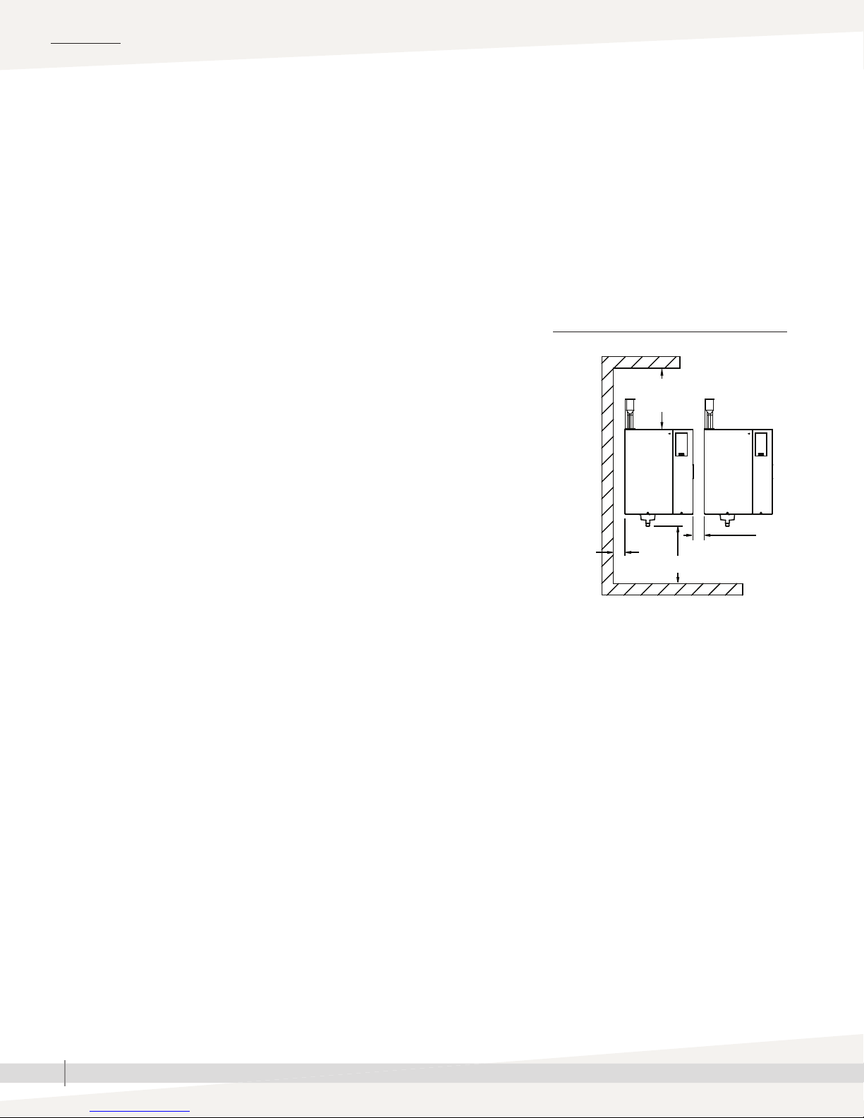
FIGURE 8-1: XT SERIES HUMIDIFIER
RECOMMENDED MINIMUM CLEARANCES
36" (914 mm)
front clearance
16"
(400 mm)
3"
(76 mm)
15" (380 mm)
3" (76 mm)
between
units
OM-7664
• Required clearances (see Figure 8-1)
• Electrical connections
Electrical power supply connections are at the lower or upper right rear
corner of the unit. See “Humidifi er wiring” on Pages 17 and 18.
• Supply water and drain piping connections
Water supply piping and drain connections are at the bottom of the
cabinet. See “Piping” on Page 13.
• Exterior wall insulation
Install the humidifi er on an exterior wall only if the wall is properly
insulated.
DISPERSION CONTROL DEVICES
See page 20 for recommended installation locations for the dispersion
assembly and associated control devices.
XT SERIES INSTALLATION, OPERATION, AND MAINTENANCE MANUAL
8
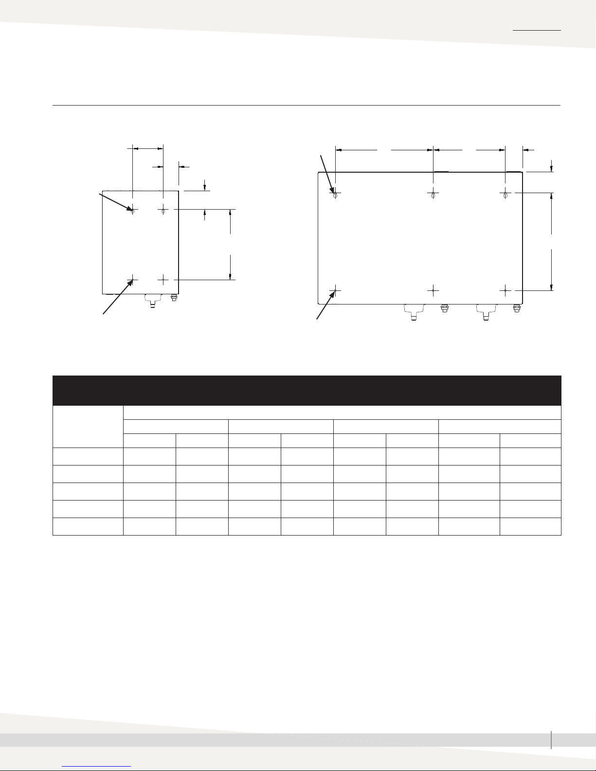
Mounting
FIGURE 9-1: XT SERIES HUMIDIFIER MOUNTING KEYHOLE LOCATIONS
INSTALLATION
Models XTP 002 through 048
A
0.390" x 0.719"
(9.9 x 18.3 mm)
dia. keyholes
0.390" (9.9 mm)
dia. holes
B
C
D
OM-7969
Table 9-1:
XT Series humidifier mounting keyhole dimensions
Dimension
A 3.9 100 7.1 180 7.5 190 14.0 356
002, 003, 006 010, 017 025, 033, 042, 048 050, 067, 083, 096
inches mm inches mm inches mm inches mm
0.390" x 0.719"
(9.9 x 18.3 mm)
dia. keyholes
0.390" (9.9 mm)
dia. holes
Model XTP
Models XTP 050 through 096
E
A
B
C
D
OM-7970
B 3.0 75 3.6 92 3.4 86 3.3 84
C 3.2 81 4.4 112 4.1 104 4.1 104
D 14.0 355 16.3 414 18.9 480 18.9 480
E ——————19.0 483
XT SERIES INSTALLATION, OPERATION, AND MAINTENANCE MANUAL
9
INSTALLATION
Mounting
Unpack the humidifi er from the shipping carton, and remove the cabinet doors
and steam cylinder (see removing steam cylinder instructions below).
WARNING
Note: When fi rst unpacking the humidifi er, cut and remove the shipping strap
that goes around the cylinder and through the cylinder guides. This strap
does not need to be replaced.
REMOVING STEAM CYLINDER
If sent to this page from the “Maintenance” section, and the humidifi er has
been operating, make sure the cylinder is empty and cooled before removing
it. See the shutdown and cool-down procedures on Page 49.
1. Carefully pull the electrode plugs straight up off the cylinder to ensure no
damage to the plug boot occurs.
2. Disconnect the high water sensor wire.
3. Place hands palms-down below cylinder on both sides of drain outlet.
4. Press up against bottom of cylinder with backs of hands while pressing
down against cabinet floor with fingers.
5. Raise cylinder until drain outlet clears drain valve body and the side tabs
on the cylinder have cleared the cylinder guides. Remove cylinder from
cabinet.
WALL MOUNTING HUMIDIFIER
Mount the humidifi er level and plumb using the lag bolts provided. Follow the
instructions below for mounting on a wood stud wall.
Mounting hazard
Mount humidifi er per the instructions
in this manual and to a structurally
stable surface. Improper mounting of
the humidifi er can cause it to fall or tip,
resulting in severe personal injury or
death.
1. Mount spanner boards on wall, spanning at least two studs. Position one
board at top of cabinet (for the lag bolts), and other board at bottom of
cabinet.
2. Predrill pilot holes in spanner boards, and secure humidifier to spanner
boards with lag bolts.
Note: Use the appropriate mounting methods and mounting hardware for other
wall types.
XT SERIES INSTALLATION, OPERATION, AND MAINTENANCE MANUAL
10
Fill cup extension kit
INSTALLATION
A fi ll cup extension (Figure 11-1) is required for the following:
• All XT Series humidifi ers using Ultra-sorb or Rapid-sorb
• When developed length of steam tubing is more than 20' (6 m) and duct
static pressure exceeds 2" wc (498 Pa)
REMOVING EXISTING FILL CUP
Remove the existing fi ll cup as follows:
1. Remove steam cylinder from XT cabinet (if not already out).
2. Expand spring clamps and slide them up cylinder fill hose and supply
water hose, and disconnect hoses from cylinder fill hose connection and
fill valve adapter.
3. Disconnect overflow hose from overflow elbow.
4. Remove fill cup and hoses (fill cup is press fit into top of XT cabinet).
INSTALLING FILL CUP EXTENSION KIT
1. Remove steam cylinder(s) from XT cabinet (if not already out).
2. Route fill cup extension kit hoses into cabinet through fill cup hole, and
fasten extension bracket as shown with two screws provided.
3. Route hoses along back of cabinet interior to provide clearance for
cylinder.
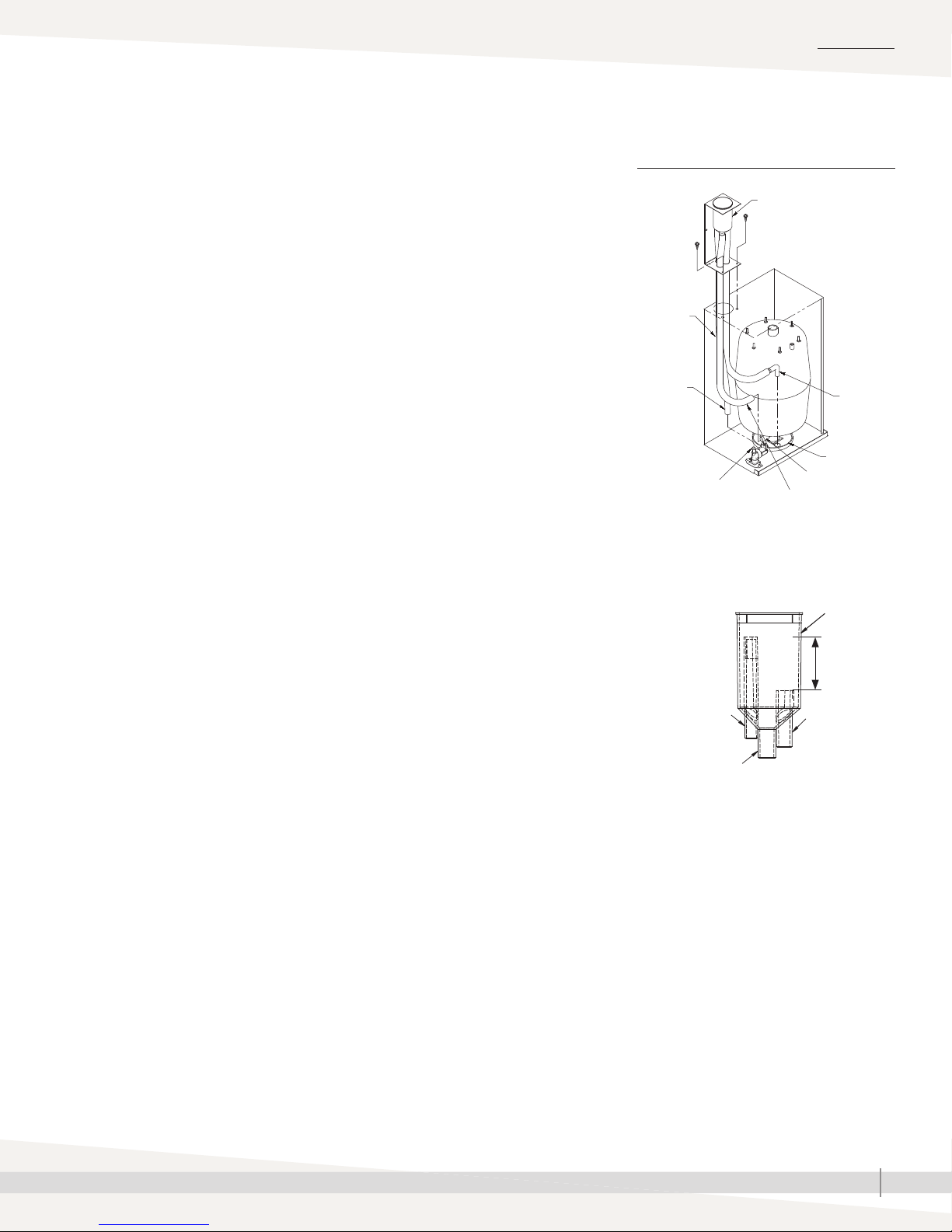
FIGURE 11-1: FILL CUP EXTENSION KIT
Fill cup
(see inset below)
Overfl ow
hose (C)
Supply
water
hose (A)
Fill valve adapter
Cylinder fi ll
hose (B)
Overfl ow
elbow
Drain cup
plate
Cylinder fi ll hose
connection
OM-7971-XT
Fill cup
4. Cut supply water hose (small-diameter hose) (A) to length so it can attach
to fill valve adapter without kinking.
5. Expand spring clamp and slide it onto supply water hose (A) far enough
so it will not interfere, then push hose onto fill valve adapter. Expand and
slide spring clamp into place.
6. Cut cylinder fill hose (bottom, center hose) (B) to length so it can attach to
cylinder fill hose connection without kinking.
7. Expand spring clamp and slide it onto cylinder fill hose (B) far enough
so it will not interfere, then push hose onto cylinder fill hose connection.
Expand and slide spring clamp into place.
8. Cut overflow hose (C) to length so it can attach to overflow elbow
without kinking.
9. Push overflow hose onto overflow elbow. Spring clamp is not required on
this connection.
Supply water (A)
Cylinder fi ll (B)
1" air gap
Overfl ow (C)
OM-7629
XT SERIES INSTALLATION, OPERATION, AND MAINTENANCE MANUAL
11
INSTALLATION
Steam cylinder
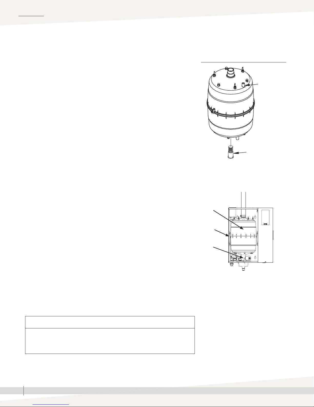
INSTALLING STEAM CYLINDER
1. Make sure strainer is pressed into steam cylinder drain outlet and strainer
flange is flush with bottom of cylinder outlet. See Figure 12-1.
2. Use water to lubricate drain outlet on bottom of cylinder and O-ring in
drain valve body. See Figure 12-1.
Note: Because of tight clearances, perform Steps 3 through 4 only if servicing
Models XTP 002 through 017 with top-mounted steam blower. For all
other models, skip to Step 5.
3. Slide steam hose that connects to cylinder and steam blower up
until it is engaged on steam inlet of steam blower and tight against
bottom of steam blower.
4. Slide steam outlet of new cylinder all the way up into open end of
steam hose from Step 3.
5. With Warning label on cylinder facing you, lower cylinder drain outlet into
drain valve body, and rotate cylinder so side tabs line up with cylinder
guides inside cabinet. Push down on cylinder until drain outlet is fully
seated in drain valve body.
6. Slide steam hose down so it is fully engaged on cylinder steam outlet.
Re-install hose clamp(s).
FIGURE 12-1: STEAM CYLINDER
INSTALLATION
High water
sensor pin
OM-7632
Strainer
7. Connect high water sensor (yellow) wire to single pin surrounded by
plastic shoulder on cylinder.
8. Connect electrode wires to pins on top of cylinder. Make sure all plugs fit
snugly and are fully engaged on pins.
Important: Three phase cylinders have color-coded dots on the cylinder
and color bands on the electrode plugs. When connecting the plugs, match
the band colors on the plugs with the dot colors on the cylinder. Refer to the
wiring diagram shipped with the humidifi er if necessary.
CAUTION
If cylinder plugs become loose, damage to the humidifi er may occur. Obtain
replacement plugs from DriSteem. See “Replacement parts” on Pages 57 and
59 for part numbers.
Warning
label
Cylinder
guide
Drain valve
body
OM-7972-XT
XT SERIES INSTALLATION, OPERATION, AND MAINTENANCE MANUAL
12
INSTALLATION
Piping:
SUPPLY WATER PIPING
Supply water and drain
Use only copper for supply water piping; do not use rubber or plastic. The
standard supply water connection before the fi ll valve is a 1/4" FIP.
Note: The supply water connection size is 3/8"BSP [DN10] in Europe.
In cases where water hammer may be a possibility, consider installing a shock
arrestor. Water pressure must be 25 to 80 psi (175 to 550 kPa).
DRAIN PIPING
Drain piping must be code-approved, 3/4" (DN 20) ID material rated for
212 °F (100°C) minimum.
The drain cup has an integral grounding plate and requires a fi eld-installed
1" (25 mm) air gap to a drain funnel to prevent conduction of electricity in the
drain line.
The XT Series humidifi er features user-selectable drain water tempering. When
drain water tempering is selected, the humidifi er tempers drain water by
opening the fi ll valve whenever the drain valve is energized to cool drain water
before it enters the drain. Drain water tempering keeps water entering the
drain line less than 140°F (60°C). Manually energizing the drain valve when
the supply water is shut off can allow 212 °F (100 °C) water to enter the drain
line.
Important: Thoroughly fl ush supply
water piping to remove pipe residue and
stagnant water before connecting piping to
humidifi er. Pipe residue and stagnant water
in water supply piping can cause foaming,
preventing humidifi er from reaching required
steam capacity.
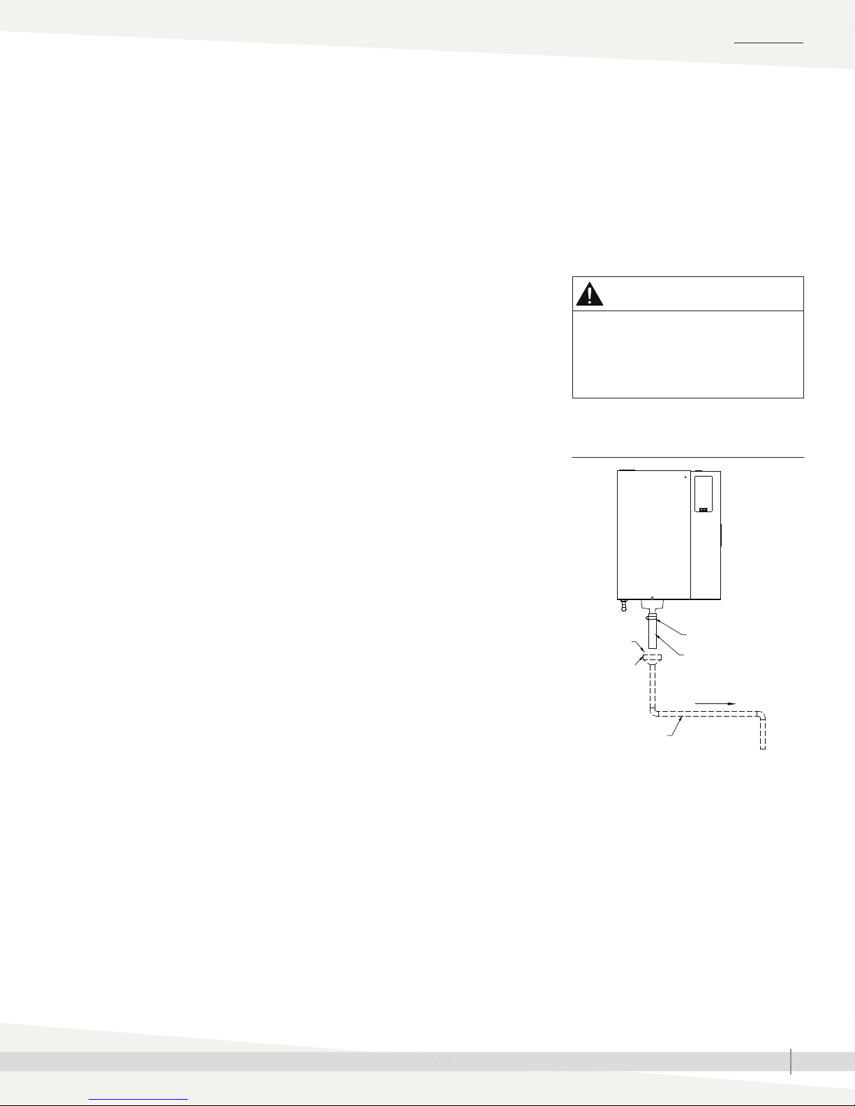
WARNING
Hot drain pipes
Drain piping surface may be hot.
Touching or contact with hot pipe may
cause severe personal injury.
FIGURE 13-1: DRAIN PIPING DETAIL
Observe the following precautions when selecting and installing drain piping
to ensure personal safety and material integrity:
• When using copper or other metallic drain piping, ground the drain piping
to the earth ground lug in the XT Series humidifi er.
• Chlorinated polyvinyl chloride (CPVC) piping is a non-metallic alternative
for drain piping. It is rated up to 212°F (100°C) for intermittent-use, lowpressure applications.
The connection size for the steam cylinder drain is 1" (DN25) hose. Do not
reduce this connection size. If drainage by gravity is not possible, use a
reservoir pump rated for 212 °F (100 °C) water.
The open drain must be at least 12” (300 mm) below the bottom of the XT
humidifi er, to help prevent steam condensation on the humidifi er. Use the 12”
(300 mm) drain hose provided and position above fi eld-installed open drain.
Alternately, route drain line away from beneath humidifi er to open drain. See
Figure 13-1.
AUTOMATIC DRAIN WATER TEMPERING
XT Series humidifi ers are shipped with drain water tempering set to ON for
North America (OFF for Europe). To activate automatic drain water tempering
see the Vapor-logic Installation and Operation Manual.
OM-7591
1" (25 mm)
air gap
Open drain
3/4" (DN20) I.D.
* Ships with humidifi er
• Dashed lines indicate provided by installer
• The open drain must be at least 12”
(300 mm) below the bottom of the
XT humidifier, to help prevent steam
condensation on the humidifier.
Hose clamp*
Drain hose*
Pitch 1/8"/ft (1%)
toward drain
To drain
XT SERIES INSTALLATION, OPERATION, AND MAINTENANCE MANUAL
13

INSTALLATION
Piping:
FIGURE 14-1: XT SERIES HUMIDIFIER FIELD PIPING OVERVIEW
Drain hose and clamp*
Fill valve with 1/4" FIP
(3/8"BSP [DN10] in
Europe) supply water
connection
Shock arrester
(by installer)
recommended
to reduce water
hammer
Metallic water
supply line
Field piping overview
Steam hose or tubing. DriSteem
recommends tubing for runs longer than
10' (3 m). See Table 26-1 for maximum
tubing lengths. Tubing must be grounded.
Install
plumb
Pitch 1/8"/ft (1%) toward drain
1¼" (DN32) drain piping after
second drain connection, or if
piping run is over 10’ (3 m).
Floor
drain
3/4" (DN20) drain piping up to
second drain connection
1" (25 mm) air gap required to
isolate unit drain piping from sanitary
drain piping. Locate air gap only in
spaces with adequate temperature
and air movement to absorb fl ash
steam, or condensing on nearby
surfaces could occur.
Open drains required directly
below humidifi er drains to prevent
downstream drain line blockage
from causing water to back up into
cylinder. Refer to governing codes
for drain pipe size and maximum
discharge water temperature. Install
spill funnels plumb to fl oor drain.
Notes:
• Dashed lines indicate provided by installer.
• Two-cylinder model shown.
* Ships with humidifi er
3/8" (DN10) copper water supply line; water
pressure must be 25 to 80 psi (175 to 550 kPa).
Inlet strainer, by installer
Supply valve, by installer
OM-7973
XT SERIES INSTALLATION, OPERATION, AND MAINTENANCE MANUAL
14
INSTALLATION
Piping:
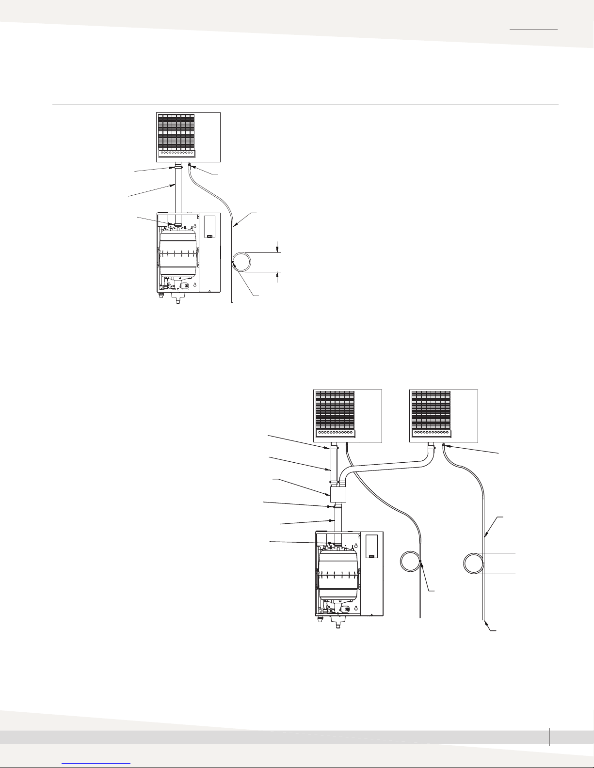
FIGURE 15-1: PIPING FROM XT SERIES HUMIDIFIER TO REMOTE XT STEAM BLOWER
Hose clamp (provided)
Steam hose
(purchased separately
from DriSteem)
Hose clamp (provided)
XT steam blowers
Plastic tie
OM-7974
To open drain or humidifi er fi ll cup.
Water seal is required, whether condensate is piped to
open drain or returned to humidifi er fi ll cup.
Notes:
• Maximum recommended distance between humidifi er
and XT steam blower is 10’ (3 m).
• Models XTP 042 through 096 are not intended for use
with a steam blower.
Condensate hose (purchased
separately from DriSteem)
7” (178 mm) water seal
Plastic tie
Hose clamps
(provided)
Steam hose
(purchased separately from DriSteem)
Stainless steel Y connector*
Hose clamp*
Steam hose*
Hose clamp*
* Provided in optional connector
kit Part No. 191070-102
OM-7975
Model XTP 025 only
Plastic tie
Condensate
hose
(purchased
separately
from DriSteem)
7” (178 mm)
water seal
Plastic tie
To open drain or
humidifi er fi ll cup.
Water seal is
required, whether
condensate is
piped to open
drain or returned
to humidifi er fi ll
cup.
XT SERIES INSTALLATION, OPERATION, AND MAINTENANCE MANUAL
15
INSTALLATION
Piping: XT steam blowers
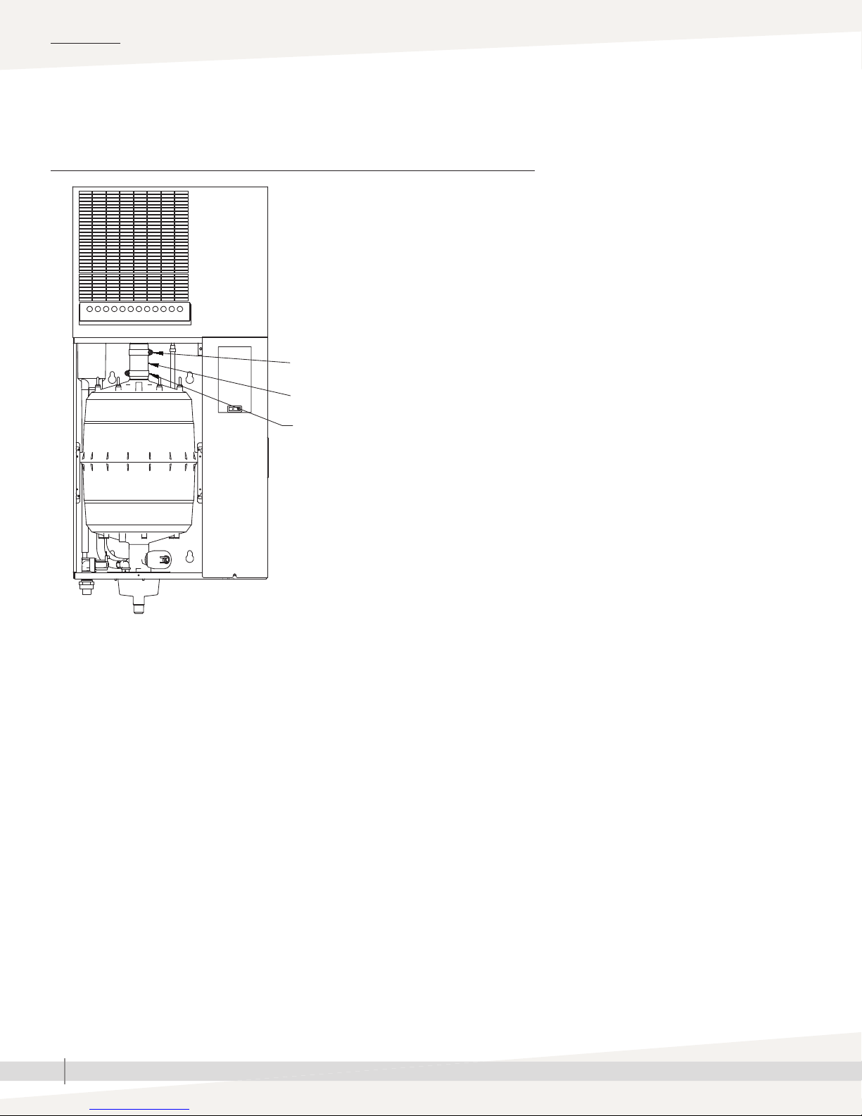
FIGURE 16-1: PIPING FROM XT SERIES HUMIDIFIER TO TOP-MOUNTED XT STEAM
BLOWER
Hose clamp (provided)
Steam hose (provided)
Hose clamp (provided)
OM-7976
Notes:
• Maximum recommended distance between humidifi er and XT steam blower is 10’ (3 m).
• Models XTP 025 and 033 are not intended for use with a direct-mounted steam blower.
• Models XTP 042 through 096 are not intended for use with a steam blower.
XT SERIES INSTALLATION, OPERATION, AND MAINTENANCE MANUAL
16
Humidifi er wiring
All wiring must be code approved and in accordance with the unit wiring
diagram. Power supply wiring must be rated for 105 °C. See Figure 17-1
for the humidifi er wiring diagram locations.
When selecting a location for installing the humidifi er:
• Avoid areas close to sources of electromagnetic emissions such as power
distribution transformers.
• Do not loop power wiring.
• Do not use aluminum wire.
CONDUIT KNOCKOUTS
Conduit and control wiring knockouts are provided on the XT Series humidifi er
cabinet. See Figure 5-1.
INSTALLATION
WARNING
Electric shock hazard
Only qualifi ed electrical personnel
should perform fi eld wiring installation
procedures. Improper wiring or contact
with energized circuits may cause
property damage, severe personal
injury, or death as a result of electric
shock and/or fi re.
CONTROL COMPONENT PLACEMENT
Follow the guidelines on Page 19 for placing humidistats, transmitters, and
airfl ow proving switches.
CAUTION
Adding conduit connections not recommended
Adding alternate conduit connections is not recommended. If you must make
additional holes in the humidifi er cabinet, protect all internal components from
debris, and vacuum out the cabinet when fi nished. Failure to follow these precautions
can damage sensitive electronic components and void the DriSteem warranty.
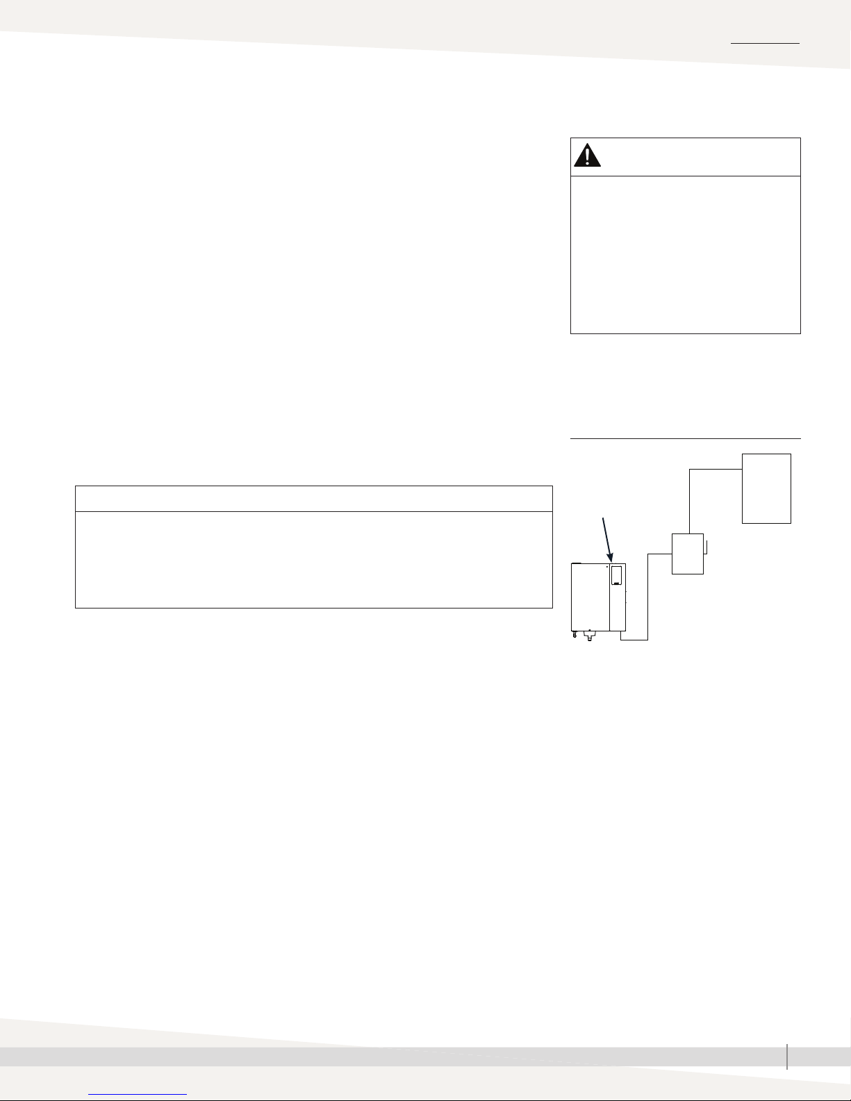
FIGURE 17-1: FIELD WIRING
REQUIREMENTS
Wiring
diagram
inside of
humidifi er
cabinet
Power supply
Fused disconnect
OM-7692
XT Series humidifi er
Notes:
• Control wiring and power wiring must be
run in dedicated or separate earthed metal
conduit, cable trays, or trunking.
• Separate the line voltage wiring from low
voltage control circuit wiring when routing
electrical wiring inside the humidifi er
cabinet.
• Do not use chassis or safety grounds as
current-carrying commons. Never use a
safety ground as a conductor or neutral to
return circuit current.
• For circuit protection requirements, see
recommended fusing in Table 4-1.
XT SERIES INSTALLATION, OPERATION, AND MAINTENANCE MANUAL
17
 Loading...