

DriSteem XT-10, XT-20, XT-100, XT-30, XT-150 Installation, Operation And Maintenance Manual
...
XT Series
Electrode Steam Humidifier
Installation, Operation,
and Maintenance Manual

Safety precautions
ATTENTION INSTALLER
Read this manual before installing
humidifier.
Leave manual with product owner.
DRI-STEEM technical support
800-328-4447
WARNING!
is product must be installed by qualied HVAC and electrical
contractors and in compliance with local, state, and federal codes.
Improper installation may cause property damage, severe personal
injury, or death as a result of electric shock, burns, and/or re.
Page ii • DRI-STEEM XT Series Electrode Steam Humidifier Installation, Operation, and Maintenance Manual

Table of contents
Installation
Specifications ........................................... 2
Dimensions ............................................ 3
Choosing a location .....................................4
Mounting the humidifier .................................5
Fill cup extension installation ............................. 7
Supply water and drain piping ............................8
Field wiring ...........................................11
Humidistat and transmitter placement ....................13
Wiring diagrams ....................................... 14
Dispersion ............................................20
General instructions
Selecting the dispersion assembly location .............20
Interconnecting piping requirements ..................21
Drip tee installation ................................24
Single Tube and Multiple Tube .......................25
Rapid-sorb
........................................29
XT Steam Blower
................................20
................................... 36
Operation
Principle of operation ..................................44
End-of-season drain ....................................45
Extended shutdown ....................................45
Safety functions ........................................45
Display panel operation .................................46
Operating modes ......................................47
Sequenced application ..................................54
Humidifier start-up ....................................54
System messages .......................................56
Maintenance
Maintenance procedures
................................58
Troubleshooting .......................................61
Replacement parts .....................................65
Two-year limited warranty .......................Back cover
DRI-STEEM XT Series Electrode Steam Humidifier Installation, Operation, and Maintenance Manual • Page 1
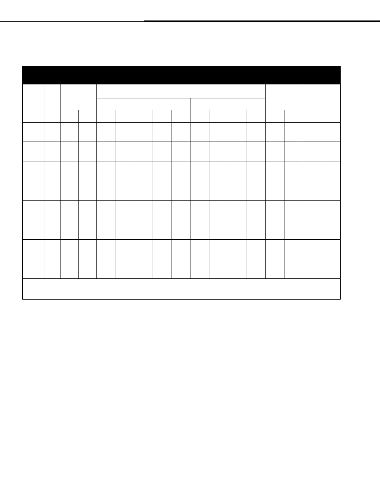
Table 2-1:
XT Series humidifier specifications
Installation: Specifications
Model
number kW
XT-10 3.4 10 4.5 16.2 14.0 12.2 7.0 5.6 9.4 8.1 4.1 3.2 27.6 12.5 29.8 13.5
XT-20 6.7 20 9.1 32.2* 27.9* 24.2 14.0 11.2 18.6 16.1 8.1 6.4 29.8 13.5 38.6 17.5
XT-30 10.1 30 13.6 —————28.0 24.3 12.1 9.7 43.0 19.5 70.5 32
XT-50 16.8 50 22.7 —————46.6 40.4 20.2 16.2 43.0 19.5 70.5 32
XT-75 25.1 75 34.0 ———————30.3 24.2 65.0 29.5 114.6 52
XT-100 33.5 100 45.4 ———————40.4 32.3 67.2 30.5 116.8 53
XT-150 50.3 150 68.0 ———————
XT-200 67.0 200 90.7 ———————
Maximum
steam capacity
lbs/hr kg/h 208V 240V 277V 480V 600V 208V 240V 480V 600V lbs kg lbs kg
Single-phase Three-phase
Current draw (amps)
2 ×
30.3**
2 ×
40.4**
2 ×
24.2**
2 ×
32.3**
Shipping
weight
137.8 62.5 242.5 110
142.2 64.5 246.9 112
Maximum
operating
weight
Note:
* For these models, shipping weight = 43 lbs (19.5 kg) and maximum operating weight = 70.5 lbs (32 kg)
** Double units require two circuits.
Page 2 • DRI-STEEM XT Series Electrode Steam Humidifier Installation, Operation, and Maintenance Manual
Installation: Dimensions
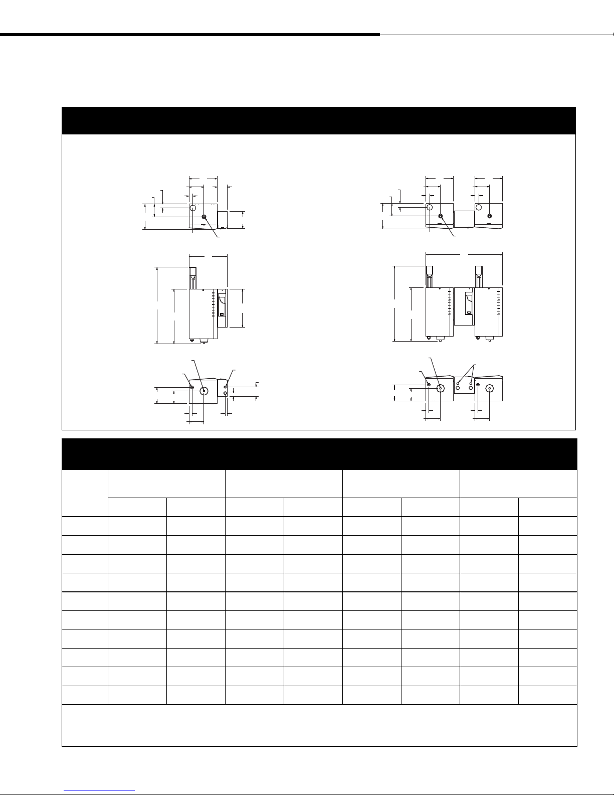
Figure 3-1:
Dimensions
Models XT-10, XT-20, XT-30, XT-50, XT-75, XT-100 Models XT-150, XT-200
Top view
1.8"
F
C
Front view
Bottom view
Water fill line connection
E
1.8"
K*
B
Drain
J
H
1.4"
G
Table 3-1:
Dimensions by model number
D
Dispersion outlet
A
4.5"
7.8"
17.4"
Electrical knockouts
4.3"
1.5"
1"
OM-7374
Top view
Front view
Bottom view
1.8"
1.8"
F
C
K*
B
Drain
Water fill line
connection
J
H
1.4" 1.4"
D
E
Dispersion outlet
G
D
E
1.8"
A
Electrical knockouts
G
OM-7419
XT-10
Callout
A 14.5 368 17.4 442 18.9 480 38.9 988
B 22.9 581 24.9 632 26.9 683 26.9 683
C 8.4 213 11.7 297 14.3 363 14.3 363
D 10.0 254 12.8 325 14.4 366 14.4 366
E 5.5 140 6.9 175 7.3 185 7.3 185
F 4.0 102 5.8 147 6.8 173 6.8 173
G 5.5 140 6.9 175 7.3 185 7.3 185
H 4.0 102 5.8 147 6.8 173 6.8 173
J 4.0 102 7.5 191 8.8 224 8.8 224
K 32.9 836 34.9 886 36.9 937 36.9 937
Note:
* Dimension K includes 10" (254 mm) for a fill cup extension. A fill cup extension is a required component when the humidifier is connected to a Rapid-sorb or Ultra-sorb dispersion
assembly or when the maximum developed length of piping/hose from humidifier to dispersion assembly/blower is more than 20' (6 m).
** XT-20 models using 208V single-phase power or 240V single-phase power have dimensions equal to Models XT-30 and XT-50.
XT-20**
inches mm inches mm inches mm inches mm
DRI-STEEM XT Series Electrode Steam Humidifier Installation, Operation, and Maintenance Manual • Page 3
XT-30
XT-50
XT-75
XT-100
XT-150
XT-200
Choosing a location
Important:
Install humidifier only in locations that meet
the following temperature and relative
humidity (RH) requirements:
Maximum ambient temperature:
104
Minimum ambient temperature:
41
Maximum ambient humidity:
80% RH (non-condensing)
Note:
To open the humidifier electrical access door,
rotate the screw counter-clockwise ¼ turn.
The door pivots toward the front of the unit
from the bottom of the door. To close the
electrical access door, position screw slot so
that it is horizontal and then push the door
shut. Make sure sides of painted door go
outside stainless steel enclosure.
To open the humidifier steam cylinder access
door, rotate the screw counter-clockwise ¼
turn, lift door out of position, and remove
ground wire. Replace door in reverse order
of these instructions.
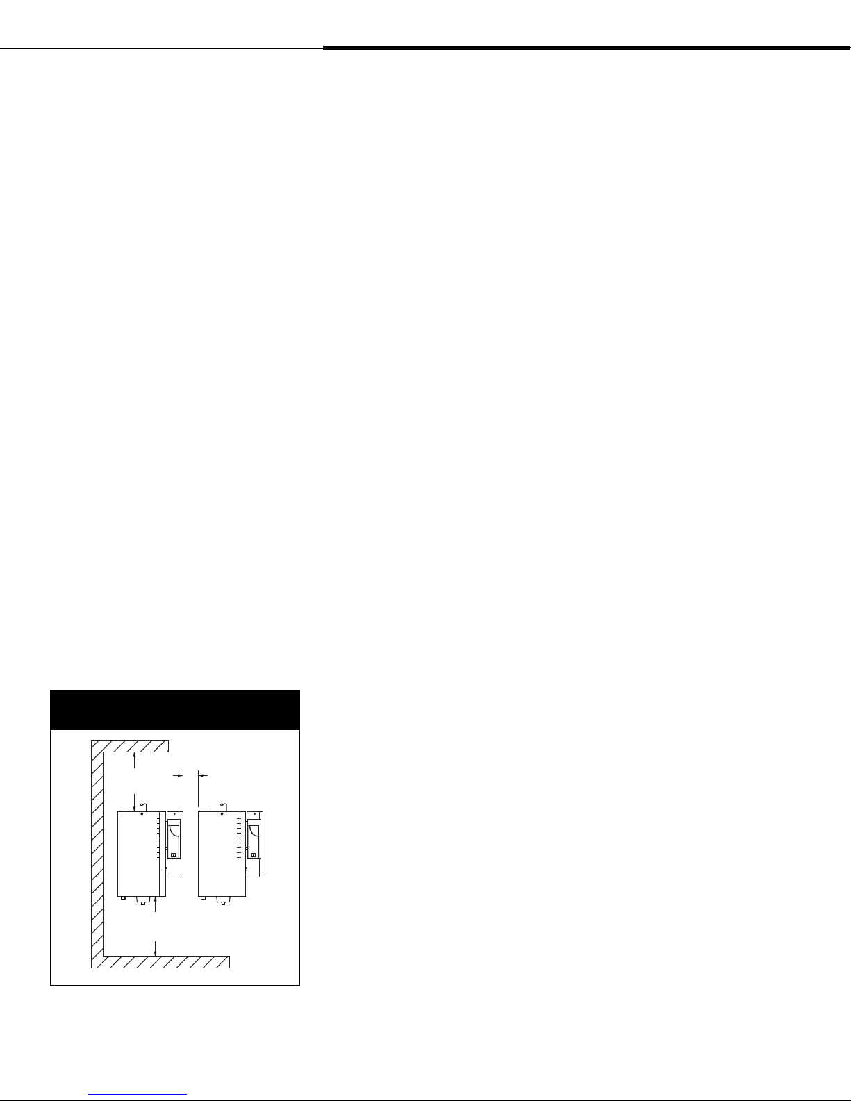
Figure 4-1:
Recommended minimum clearances
°F (40 °C)
°F (5 °C)
Choosing a location for the humidifier
When selecting a location for the humidifier, consider the following:
•
Proximity to duct
Install the humidifier near the air duct system where the
dispersion assembly will be located. The maximum recommended
length for vapor hose connecting a single humidifier to a
dispersion assembly is 10' (3 m). The maximum recommended
developed length for tubing or pipe connecting a single
humidifier to a dispersion assembly is 20' (6 m). See the
dispersion section of this manual for more information about
installing dispersion assemblies.
• Elevation of the installed dispersion assembly
The recommended installation location for the dispersion
assembly is at an elevation higher than the humidifier. However,
if the dispersion assembly must be installed at an elevation
lower than the humidifier, install a drip tee and drain as shown
in Figure 24-1. Before installing a dispersion assembly or
interconnecting piping, review all pitch requirements in the
dispersion section of this manual.
•
Required clearances (see Figure 4-1)
•
Electrical connections
Electrical power supply connections are made at the bottom panel
corner of the electrical enclosure. The system wiring is inside
the cover of the control cabinet. See the field wiring instructions
starting on Page 11.
• Supply water and drain piping connections
Water supply piping connections are made on the bottom left
side of the unit. Drain piping connections are made at the bottom
center of unit. See the field piping illustration and instructions
starting on Page 8.
• Exterior wall insulation
Do not install the humidifier on an exterior wall unless that wall
is properly insulated.
Top: 16"
(400 mm)
Side: 4" (100 mm)
Floor: 16" (400 mm)
Page 4 • DRI-STEEM XT Series Electrode Steam Humidifier Installation, Operation, and Maintenance Manual
Between units:
4" (100 mm)
Front:
36"
(914 mm)
OM-7359
Choosing a location for the dispersion assembly and control
devices
See Page 20 for recommended installation locations for the
dispersion assembly. See Page 13 for recommended installation
locations for control devices such as humidistats and transmitters.

Mounting the humidifier
Figure 5-1:
Mounting keyhole locations by model number
Models XT-10, XT-20, XT-30, XT-50, XT-75, XT-100 Models XT-150, XT-200
A
WARNING!
Mount humidifier per the instructions in this
manual and to a structurally stable surface.
Improper mounting of humidifier may cause
the humidifier to fall off the wall resulting in
severe personal injury or death.
A
G
D
A
D
C
E
B
F
OM-7360
D
Table 5-1:
Mounting dimensions
XT-10
XT-20*
inches mm inches mm inches mm inches mm
A 3.9 99 7.1 180 7.5 191 7.5 191
XT-30
XT-50
XT-75
XT-100
XT-150
XT-200
C
C
E
B
F
OM-7420
B 14 356 16.3 414 19.1 485 19.1 485
C 3.1 79 3.6 91 3.4 86 3.4 86
D 3 76 2.1 53 3.4 86 3.4 86
E 2.8 71 3 76 2.8 71 2.8 71
F 3.8 97 3.2 81 2.6 66 2.6 66
G — — — — — — 17.1 434
Note:
* XT-20 models using 208V single-phase power or 240V single-phase power have
dimensions equal to Models XT-30 and XT-50.
DRI-STEEM XT Series Electrode Steam Humidifier Installation, Operation, and Maintenance Manual • Page 5

WARNING!
Mount humidifier per the instructions in this
manual and to a structurally stable surface.
Improper mounting of humidifier may cause
the humidifier to fall off the wall resulting in
severe personal injury or death.
Mounting the humidifier (continued)
Prepare humidifier for mounting
Unpack unit from shipping carton and remove steam cylinder door.
Disconnect electrode and high water sensor connectors from steam
cylinder. Pull pins from brackets that retain steam cylinder. Remove
steam cylinder from drain valve body.
Mount humidifier
Mount the humidifier so that it is plumb. See Figures 8-1 and 9-1
for an installation overview.
When mounting on a wood stud wall (studs 16" [406 mm] on
center), locate studs and attach spanner board so that each of the
screws centers on a stud. Mark hole locations per Table 5-1 and
predrill 1/8" (3 mm) diameter pilot holes. Secure cabinet to spanner
board with screws provided.
When mounting on a metal stud wall, locate the studs (16"
[406 mm] on center) and drill a ¼" (6 mm) hole through the studs
and wall. Mount spanner board with ¼" (6 mm) bolts through the
wall, studs, and a backing plate on the backside of the wall and
secure with a nut and washer.
If 16" (406 mm) on-center studs are not available, mount spanner
boards on the wall, spanning two studs. If two horizontal boards
are used, locate one at the top of the cabinet for the mounting
screws and the other board located 3.5" (89 mm) on center from the
bottom of the cabinet.
For hollow block or poured concrete wall mounting, mark
mounting holes per Table 5-1. Drill pilot holes sized for the proper
concrete anchors. Secure cabinet in place using four screws.
Page 6 • DRI-STEEM XT Series Electrode Steam Humidifier Installation, Operation, and Maintenance Manual
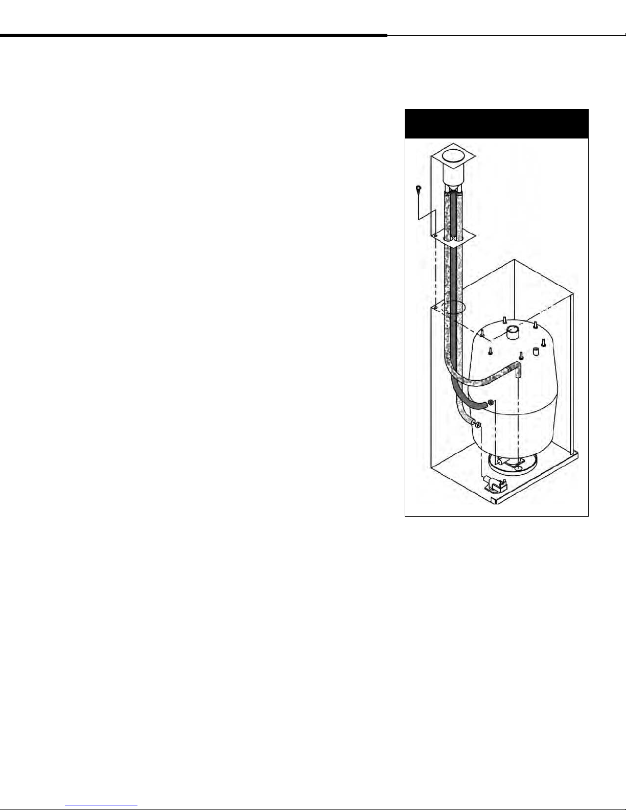
Fill cup extension installation
Install fill cup extension kit (if applicable)
A fill cup extension kit is required with all Rapid-sorb and
Ultra-sorb dispersion assemblies or when the maximum developed
length of piping/hose from humidifier to dispersion assembly/
blower is more than 20' (6 m).
1. Remove hose clamps attached to fill cup extension bracket.
2. Remove Phillips screw near large opening on top enclosure and
retain for use in Step 4.
3. Feed tubes through left rear opening on top of steam cylinder
enclosure.
4. Mount bracket with screw from Step 2 (see Figure 7-1).
5. Slip smaller hose clamp (D18) from Step 1 over smaller diameter
hose and slide open end of hose onto fill valve body connection.
Tighten hose clamp.
6. Slip larger hose clamp (D21) from Step 1 over larger diameter
hose (the one attached to cone bottom of fill cup) and slide open
end of hose onto drain valve body connection. Tighten hose
clamp.
7. Place overflow tube with elbow into hole of drain cup plate.
Replace steam cylinder
1. Slide steam cylinder (with warning label facing toward operator)
into drain valve body while making sure side tabs engage
brackets.
2. Reconnect electrode and high water sensor connectors to steam
cylinder (refer to unit wiring diagram located in electrical
enclosure).
Figure 7-1:
Fill cup extension installation
DRI-STEEM XT Series Electrode Steam Humidifier Installation, Operation, and Maintenance Manual • Page 7
OM-7385
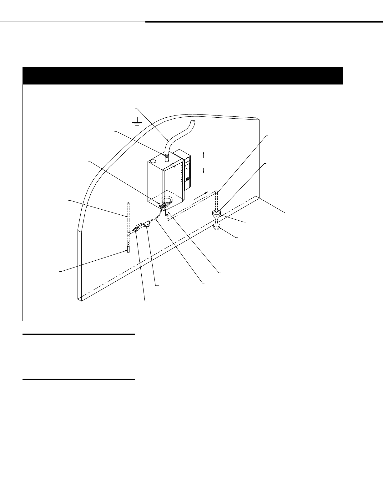
Supply water and drain piping
Figure 8-1:
Field piping overview for models XT-10, XT-20, XT-30, XT-50, XT-75, and XT-100
Steam vapor hose; may also use tubing or
pipe. See Table 22-1 for maximum piping
lengths. Tubing or pipe must be grounded.
Fill valve (with screen)
Continuous copper
water supply line;
water pressure must
be between 25 psi
and 80 psi (175 kPa
and 550 kPa)
Shock arrester
recommended
to reduce water
hammer, by installer
Adapter
Pitch 1/8”/ft (1%)
Inlet strainer,
by installer
Supply valve, by installer
¾" (DN20) metallic drain piping. If
piping run is over 10' (3 m) increase
pipe to 1¼" (DN32).
Install plumb
towards drain
Spill funnel. Plumb to floor drain
Refer to governing codes for drain pipe size and
maximum discharge water temperature. Offset
humidifier from spill funnel to prevent flash steam
from rising into the humidifier.
Hose and clamps
3/8" (DN10) O.D. copper; compression fitting on fill valve
1" (25 mm) air gap required
WARNING!
Drain piping surface may be hot. Touching
or contact with hot pipe may cause severe
personal injury.
Page 8 • DRI-STEEM XT Series Electrode Steam Humidifier Installation, Operation, and Maintenance Manual
OM-7362
Supply water quality
XT Series humidifiers use normal tap water or softened water to
generate humidification steam. Water conductivity must be within
the range of 125 to 1250 μS/cm (which, in many cases, is roughly
equivalent to 3.4 to 36.3 grains/gallon). Demineralized water cannot
be used because it is not conductive. Do not use heated supply water
because unheated supply water is required for drain water tempering.
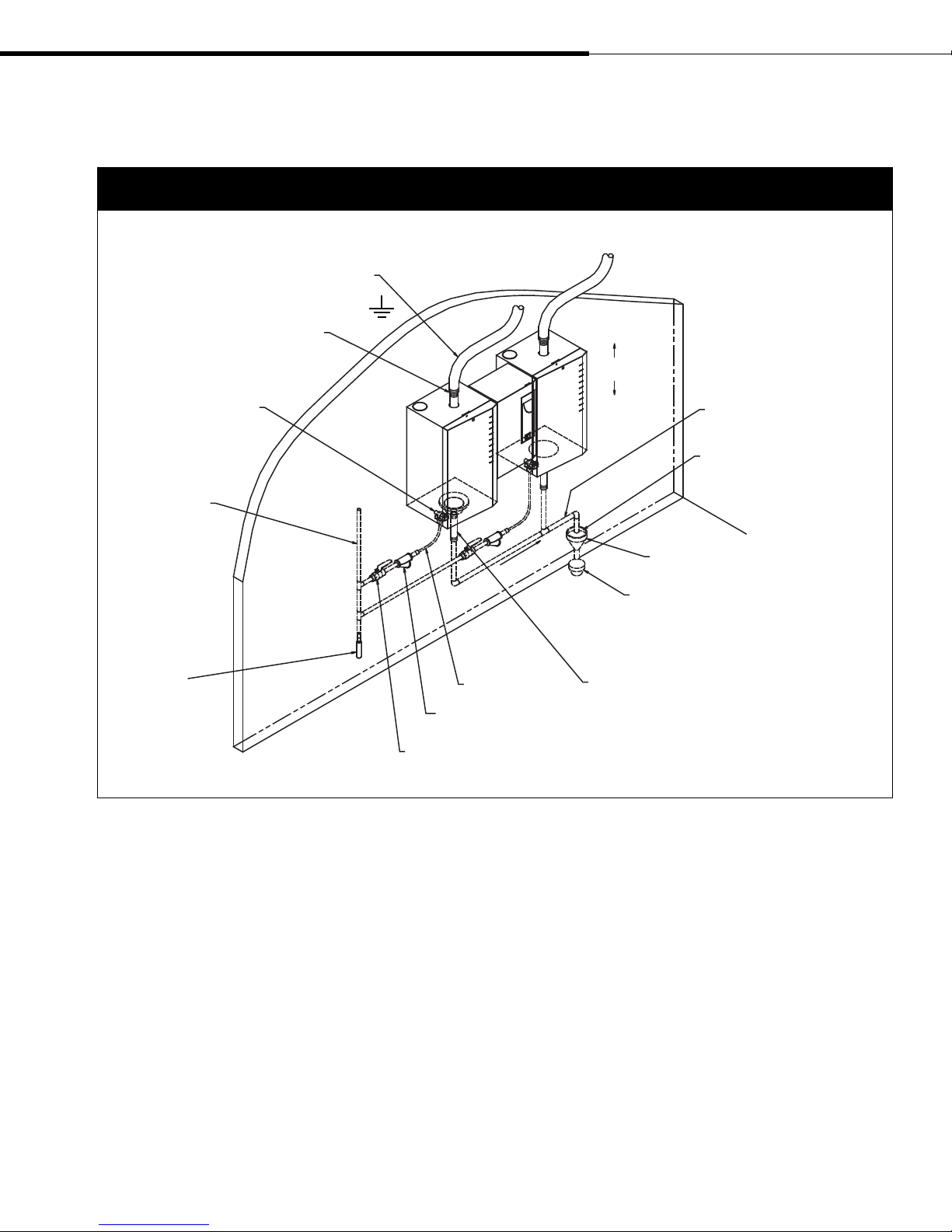
Supply water and drain piping
(continued)
Figure 9-1:
Field piping overview for Models XT-150 and XT-200
Steam vapor hose; may also use tubing or
pipe. See Table 22-1 for maximum piping
lengths. Tubing or pipe must be grounded.
Adapter
Install plumb
Fill valve (with screen)
Continuous copper
water supply line;
water pressure must
be between 25 psi
and 80 psi (175 kPa
and 550 kPa)
Shock arrester
recommended
to reduce water
hammer, by installer
Inlet strainer,
by installer
Supply valve, by installer
Pitch 1/8”/ft (1%)
towards drain
3/8" (DN10) O.D.
copper; compression fitting
on fill valve
Supply water piping
Use only copper for supply water piping—do not use rubber or
plastic. A strainer is recommended to be installed in the supply
piping before the fill valve. The fill valve connection size is a 3/8"
(DN10) compression fitting. In cases where water hammer may be a
possibility, consider installing a shock arrestor. Water pressure must
be between 25 psi and 80 psi (175 kPa and 550 kPa).
¾" (DN20) metallic drain piping up
to second drain connection, then
increase pipe to 1¼" (DN32)
1" (25 mm) air gap required
Spill funnel. Plumb to floor drain
Refer to governing codes for drain pipe size and
maximum discharge water temperature. Offset
humidifier from spill funnel to prevent flash steam
from rising into the humidifier.
Hose and clamps
OM-7362
Important: Thoroughly flush the
supply water piping to remove pipe residue
and stagnant water before connecting
piping to the humidifier. Pipe residue and
stagnant water in the water supply piping
can cause the humidifier to not reach
required steam capacity.
DRI-STEEM XT Series Electrode Steam Humidifier Installation, Operation, and Maintenance Manual • Page 9
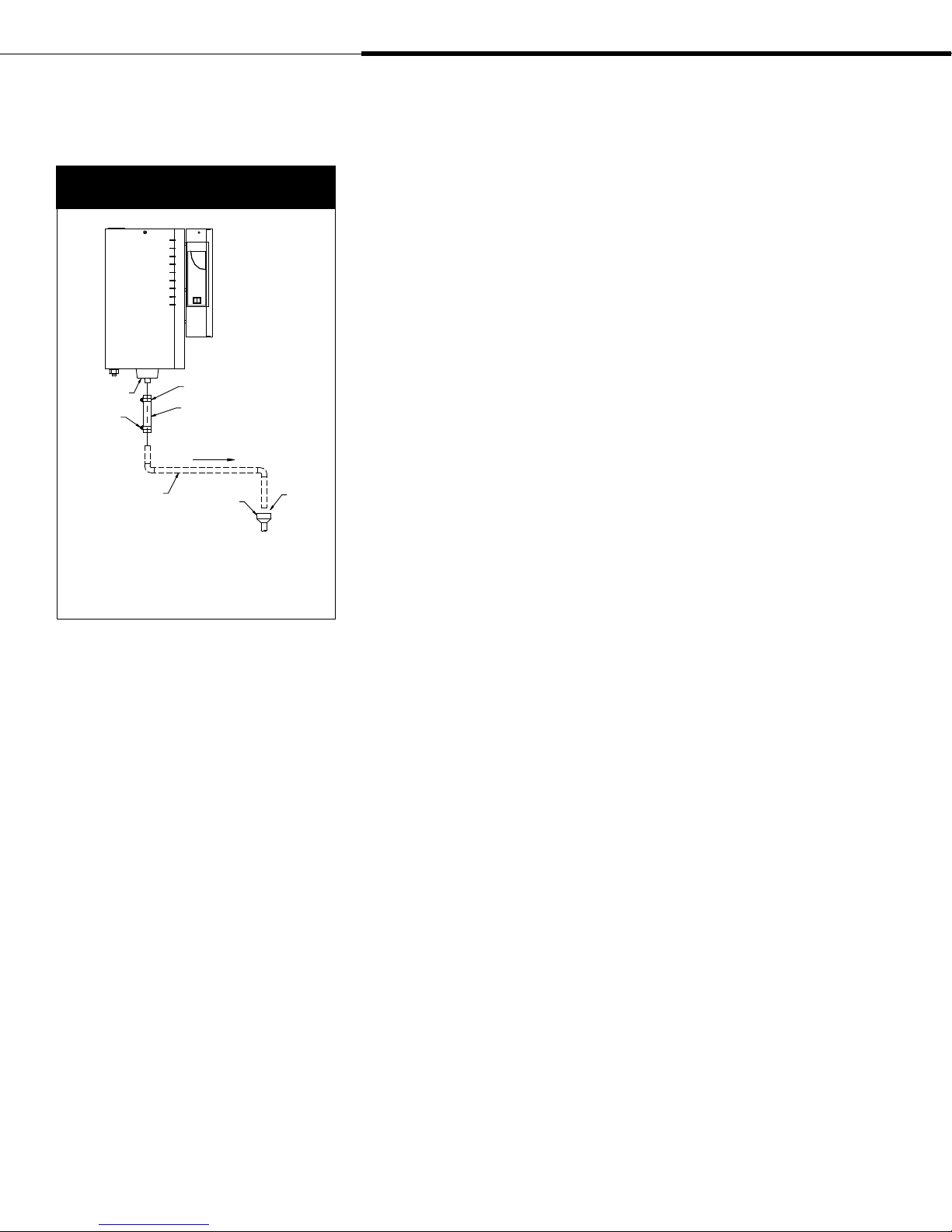
Supply water and drain piping
(continued)
Figure 10-1:
Drain piping detail
Drain cup
Hose clamp
(field supplied)
¾" (DN20) copper
Note:
* A D29 bolt hose clamp and black rubber hose
ship with each humidifier. These parts can also be
ordered from DRI-STEEM. See the replacement parts
section of this manual for part numbers.
D29 bolt hose clamp
Black rubber hose
Pitch 1/8”/ft (1%)
towards drain
Open drain
1"
(25 mm)
air gap
OM-7379
Humidifier drain piping
Drain piping must be code-approved copper or steel rated for 212 °F
(100 °C) minimum. The final connection size is ¾" (DN20) copper
for the steam cylinder drain. Do not reduce this connection size.
See Figures 8-1 and 9-1 for typical installation dimensions and
requirements.
If drainage by gravity is not possible, use a reservoir pump rated for
212 °F (100 °C) water.
A 10" (254 mm) piece of hose is provided to function as the flexible
connection from the drain cup to the field installed drain plumbing.
A D29 hose clamp is provided to secure the drain hose to the drain
cup.
See Figure 10-1 for drain piping detail.
If the equivalent length of pipe from the humidifier drain to the
plumbing system drain is more than 10' (3 m), increase the pipe size
to 1¼" (DN32).
Page 10 • DRI-STEEM XT Series Electrode Steam Humidifier Installation, Operation, and Maintenance Manual
Field wiring
Humidifier field wiring
All wiring must be in accordance with all governing codes and
with the unit wiring diagram. The unit wiring diagram is inside the
electrical control cabinet. Power supply wiring must be rated for
105 °C.
When selecting a location for installing the humidifier, avoid
areas close to sources of electromagnetic emissions such as power
distribution transformers.
Do not loop power wiring.
Do not use aluminum wire.
Field wiring connections and requirements
Conduit knockouts are provided on the bottom of the electrical
control cabinet. Control wiring knockouts are on the bottom front;
power wiring knockouts are on the bottom rear.
CAUTION! Adding alternate conduit connections is not
recommended; however, if making holes and knockouts in the
humidifier cabinet, protect all internal components from debris
and vacuum out cabinet when finished. Failure to comply with this
caution can damage sensitive electronic components and void the
DRI-STEEM warranty.
WARNING!
Only qualified electrical personnel should
perform field wiring installation procedures.
Improper wiring or contact with energized
circuits may cause property damage, severe
personal injury, or death as a result of
electric shock and/or fire.
d
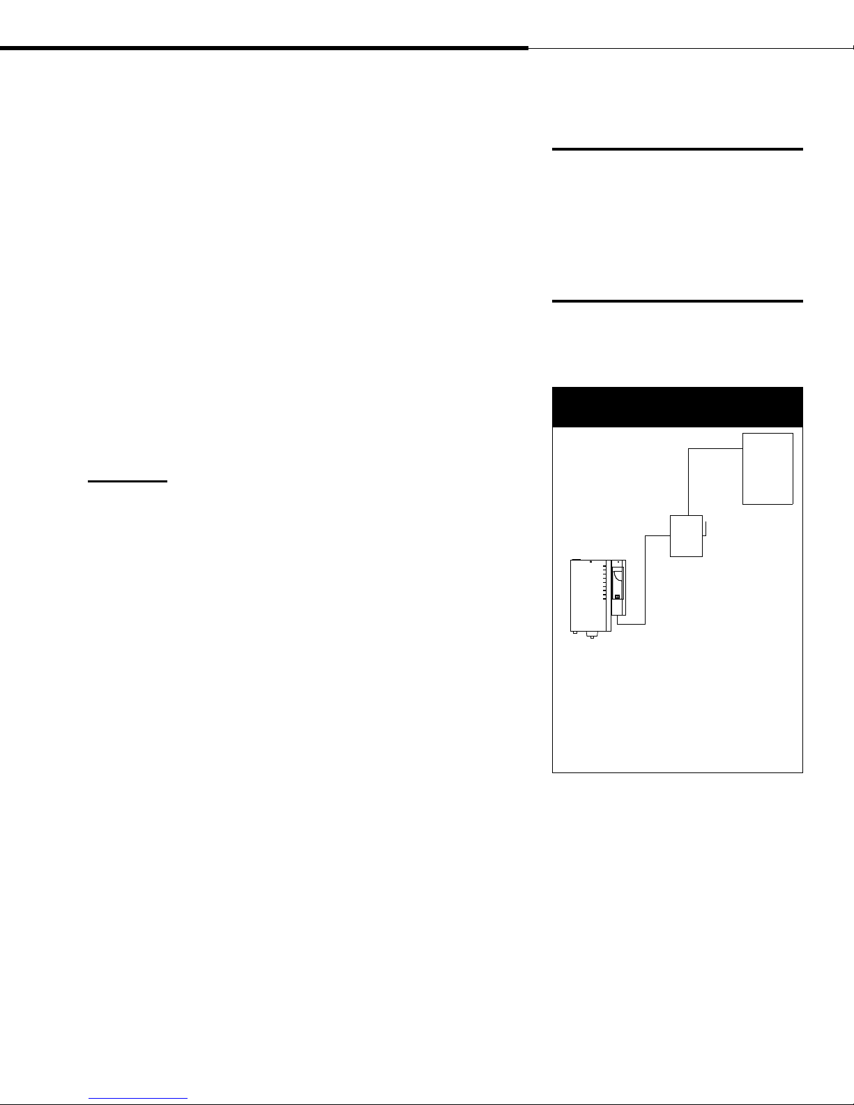
Figure 11-1:
Field wiring requirements
Power
supply
Fused
disconnect
Humidifier
Control component placement
Follow the guidelines on Page 13 for placing humidistats,
transmitters, and airflow proving switches.
More on the next page ▶
OM-7363
Notes:
• Control wiring and power wiring must be run
in dedicated or separate earthed metal conduit,
cable trays, or trunking.
• Separate the line voltage wiring from low voltage
control circuit wiring when routing electrical
wiring inside the humidifier cabinet.
• Do not use chassis or safety grounds as currentcarrying commons. Never use a safety ground as a
conductor or neutral to return circuit current.
DRI-STEEM XT Series Electrode Steam Humidifier Installation, Operation, and Maintenance Manual • Page 11

Field wiring (continued)
Proper wiring prevents electrical noise.
Electrical noise can produce undesirable
effects on electronic control circuits, which
affects controllability. Electrical noise is
generated by electrical equipment such as
inductive loads, electric motors, solenoid
coils, welding machinery, or fluorescent light
circuits. The electrical noise or interference
generated from these sources (and the
effect on controllers) is difficult to define,
but the most common symptoms are erratic
control or intermittent operational problems.
Important:
• For maximum EMC effectiveness, wire all
humidity, high limit, and airflow controls
using multicolored shielded/screened
plenum-rated cable with a drain wire for
the shield/screen. Connect the drain wire
to the shield/screen ground terminal with
wire less than 2" (50 mm) in length.
• Do not ground shield at the device end.
Below are field wiring connection instructions:
•
Connect to line power.
Refer to the wiring diagram or the data plate on the outside of the
cabinet for wire sizing amperage.
•
Connect to control signal wiring
from a humidistat, transmitter, or signal by others. See the control
wiring diagrams on pages 14-19.
•
Connect remote signal wiring.
When wired to a remote signaling device, two relays indicate
if there is a fault with draining, filling, or water level control
functions of the humidifier, or if a required maintenance interval
has been reached. See the control wiring diagrams on pages
14-19. To enable the remote signaling device, connect wiring
to control terminals 9 (N.O.), 10 (N.C.), 11 (C) for Relay 1, and
connect wiring to control terminals 26 (N.O.), 27 (N.C.), and 28
(C) for Relay 2.
•
Connect to the duct airflow proving switch and duct high limit
humidistat wiring (recommended optional devices). If not used,
jumper H-H terminals unless on/off humidistat is installed.
WARNING!
DRI-STEEM strongly recommends installing a duct airflow proving
switch and a duct high limit humidistat. These devices prevent the
humidifier from making steam when there is no airflow in the duct or
when the RH level in the duct is too high. Failure to install these devices
can result in excessive moisture in the duct, which can cause bacteria
and mold growth or dripping through the duct.
Grounding requirements
A safety grounding system that meets national, state, and local
electrical codes is required. The ground connection must be made
with solid metal to metal connections. Ground wire should be the
same size as power wiring.
Control input wiring
XT Series humidifiers accept RH or demand signals from
DRI-STEEM control components or from a signal by others. For
wiring connection requirements, first determine which control
scenario applies. Then, refer to the corresponding control input
wiring diagram shown on the following pages, or located inside the
accessory box.
Page 12 • DRI-STEEM XT Series Electrode Steam Humidifier Installation, Operation, and Maintenance Manual
Humidistat and transmitter
placement
Humidistat and transmitter locations are critical
Humidistat or transmitter location has a significant impact on
humidifier performance. In most cases, it is recommended that you
do not interchange duct and room humidity devices. Room humidity
devices are calibrated with zero or little airflow; whereas duct humidity
devices require air passing across them. Recommended humidistat and
transmitter locations (see Figure 13-1):
A This is the ideal sensing location because this placement ensures the
best uniform mix of dry and moist air with stable temperature control.
B This location is acceptable, but the room environment may affect
controllability such as when the humidistat or transmitter is too close
to air grilles, registers, or heat radiation from room lighting.
C This location is acceptable because it provides a good uniform
mixture of dry and moist air, but if an extended time lag exists
between moisture generation and sensing, make sure the control
contractor extends the sampling time.
D This location behind a wall or partition is acceptable for sampling
the entire room if the sensor is near an air exhaust return outlet. This
location is also typical of humidistat or transmitter placement for
sampling a critical area.
E These locations are not acceptable because they may not represent
actual overall conditions in the space.
F These locations are not acceptable. Do not place humidistats or
transmitters near windows, door passageways, or areas of stagnant
airflow.
G This is the best location for a duct high limit humidistat or humidity
transmitter.
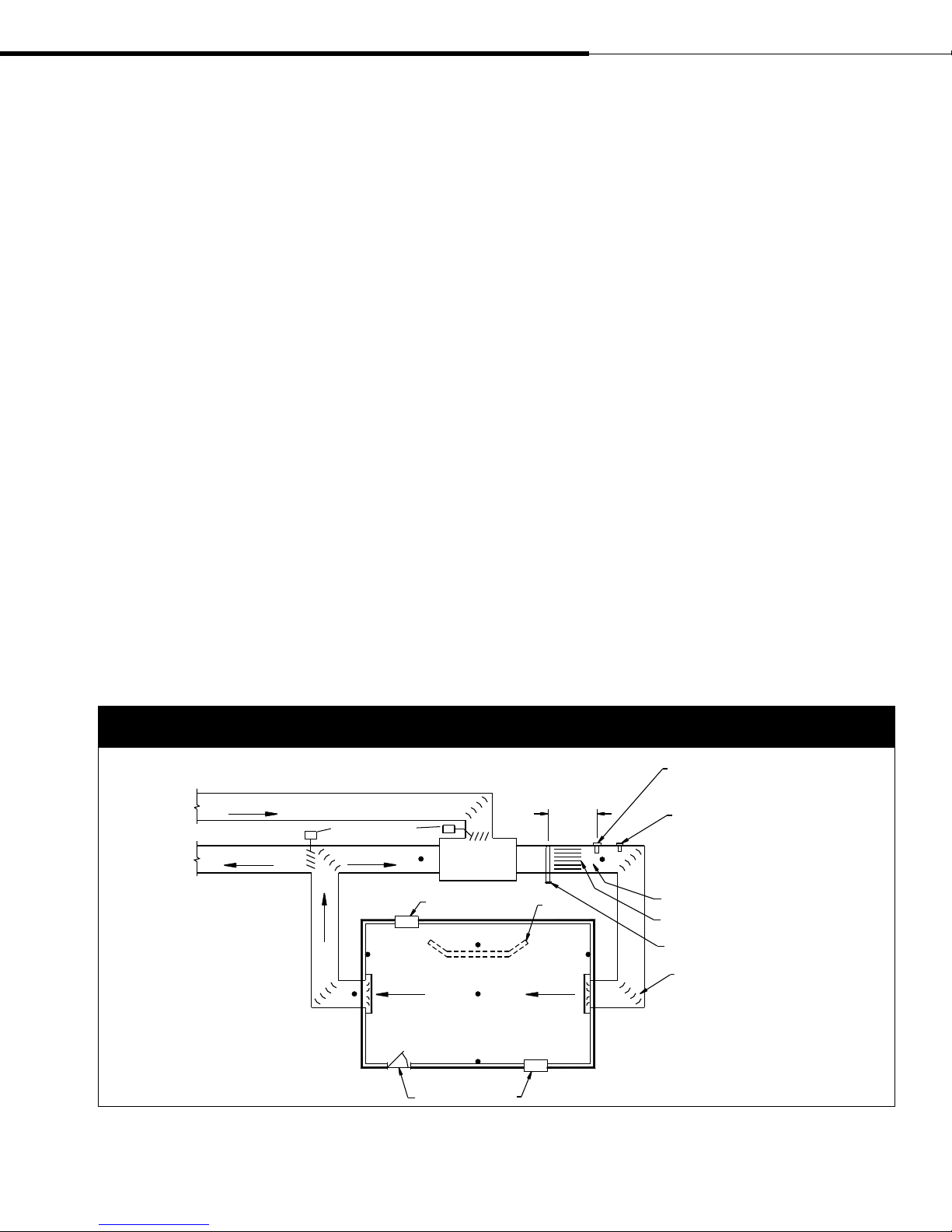
Figure 13-1:
Recommended humidistat and transmitter locations
Outside air
Damper control
Relief air
Return air
A
C
Window
E
F
Doorway
(2.4 m to 3.7 m)
minimum
AHU
Wall or
partition
D
B
EF
Window
8' to 12'
F
High limit humidistat or high limit transmitter
(set at 90% RH maximum) for VAV applications
Airflow switch or differential pressure
switch (sail type recommended for VAV
applications)
G
Vapor absorption has taken place
Point of vapor absorption
Humidifier dispersion assembly
Turning vanes
DC-1084M
DRI-STEEM XT Series Electrode Steam Humidifier Installation, Operation, and Maintenance Manual • Page 13
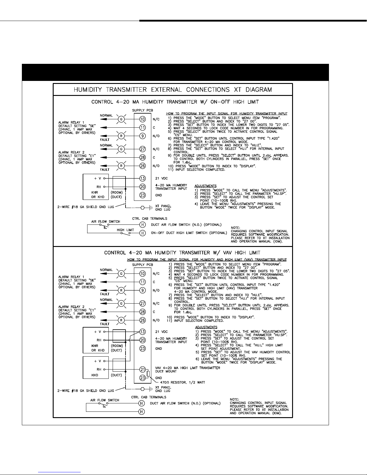
Wiring diagrams
Figure 14-1:
Control wiring diagrams for humidity transmitter external connections to XT Series humidifiers
Page 14 • DRI-STEEM XT Series Electrode Steam Humidifier Installation, Operation, and Maintenance Manual
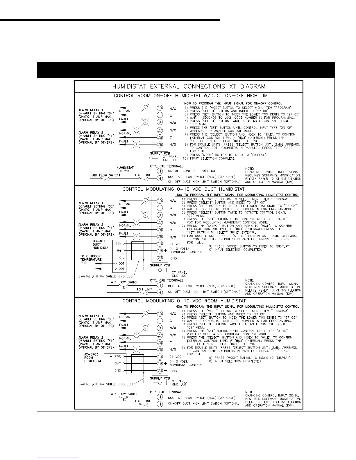
Wiring diagrams (continued)
Figure 15-1:
Control wiring diagrams for humidistat external connections to XT Series humidifiers
DRI-STEEM XT Series Electrode Steam Humidifier Installation, Operation, and Maintenance Manual • Page 15
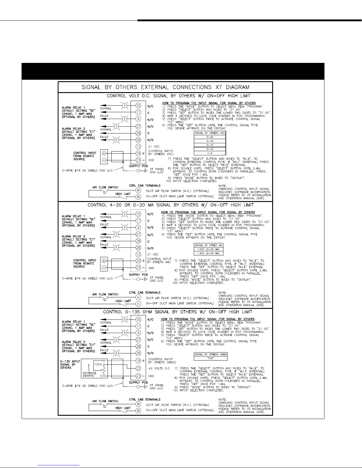
Wiring diagrams (continued)
Figure 16-1:
Control wiring diagrams for signal by others external connections to XT Series humidifiers
Page 16 • DRI-STEEM XT Series Electrode Steam Humidifier Installation, Operation, and Maintenance Manual
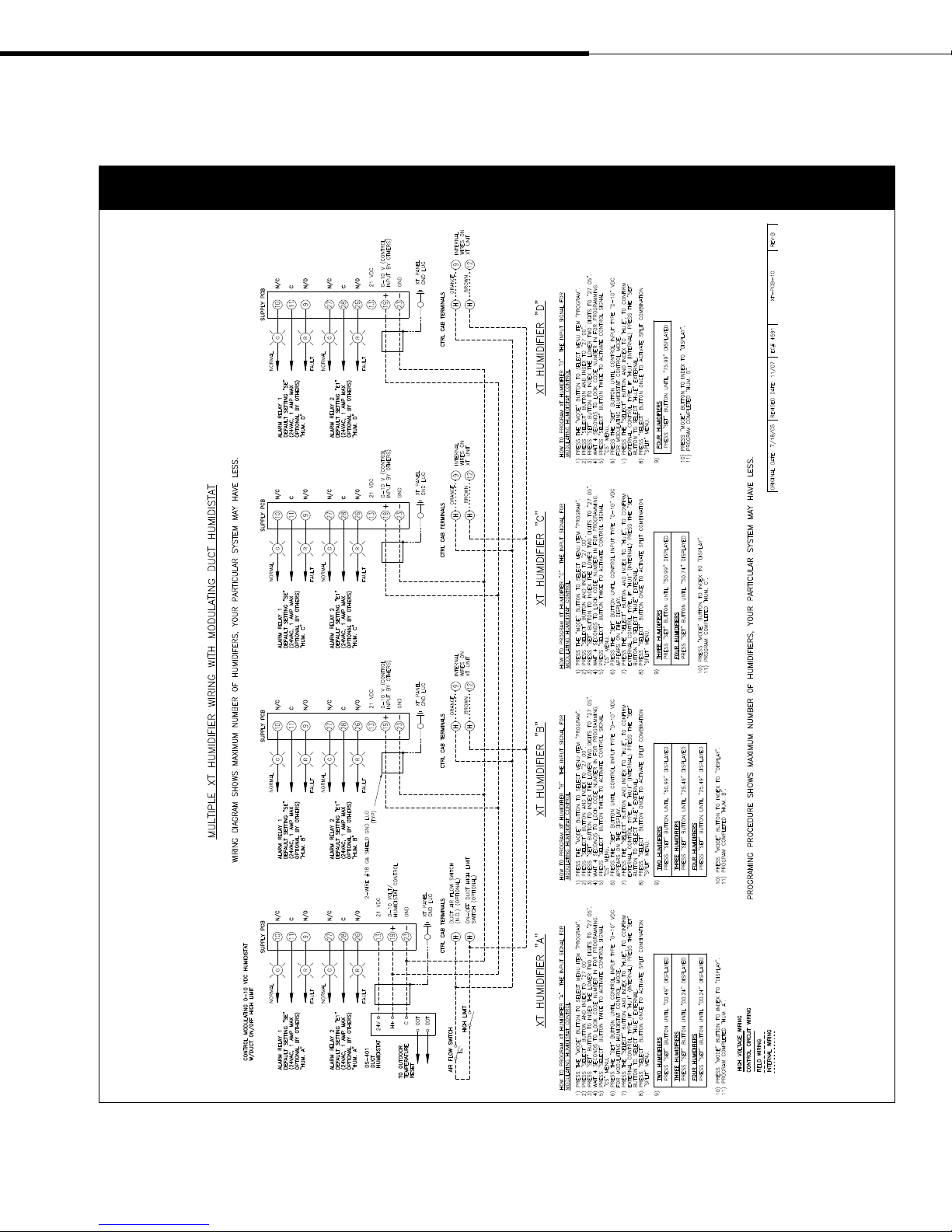
Wiring diagrams (continued)
Figure 17-1:
Wiring diagram for sequenced XT Series humidifiers with a modulating duct humidistat
DRI-STEEM XT Series Electrode Steam Humidifier Installation, Operation, and Maintenance Manual • Page 17
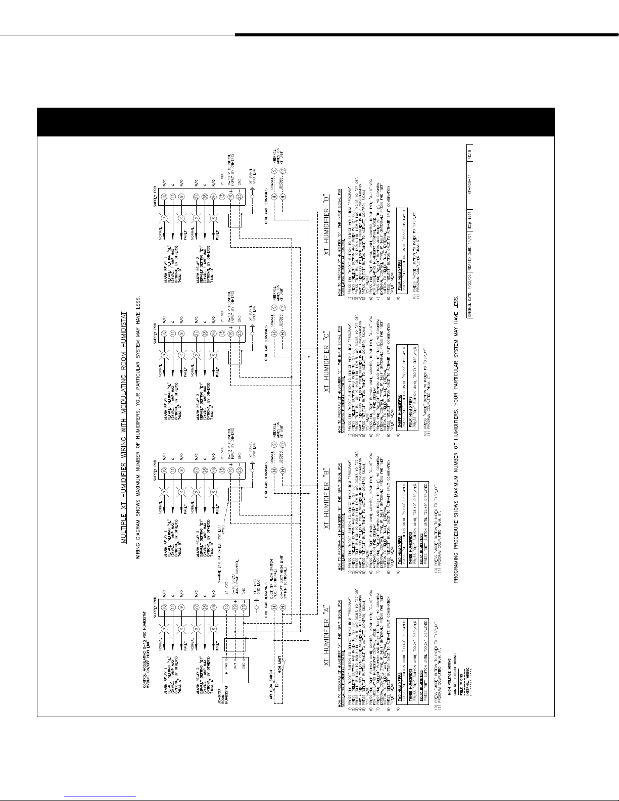
Wiring diagrams (continued)
Figure 18-1:
Wiring diagram for sequenced XT Series humidifiers with a modulating room humidistat
Page 18 • DRI-STEEM XT Series Electrode Steam Humidifier Installation, Operation, and Maintenance Manual

Wiring diagrams (continued)
Figure 19-1:
Wiring diagram for sequenced XT Series humidifiers with a modulating 0-10 VDC signal by others
DRI-STEEM XT Series Electrode Steam Humidifier Installation, Operation, and Maintenance Manual • Page 19

Dispersion: General instructions
Where to find more dispersion
information
In this document:
• Interconnecting piping and drip tee
installation, pages 21-24
• Single Tube and Multiple Tube installation
instructions, pages 25-28
• Rapid-sorb
pages 29-35
• XT Steam Blowers, pages 36-43
On our web site:
The following documents can be viewed,
printed or ordered from our web site,
www.dristeem.com
• Catalogs (which include dispersion
nonwetting distance graphs):
– XT Series Humidifier
– Ultra-sorb
• Installation, Operation, and Maintenance
manuals:
– Ultra-sorb
DRI-STEEM Design Guide
•
loss tables and general humidification
information)
On Dri-calc:
Dri-calc
sizing and selection software, and may be
ordered at our web site, www.dristeem.com.
Included in Dri-calc:
®
installation instructions,
®
(includes steam
®
is our humidification system
Selecting the dispersion assembly location
• For each dispersion device, DRI-STEEM documents distances
required for absorption to occur. If you have questions about
absorption distances, see the absorption tables in the XT Series
catalog, available for viewing, printing or ordering at
www.dristeem.com
• It is important that the dispersion assembly be positioned where
the water vapor being discharged is carried off with the airstream
and is absorbed before it can cause condensation or dripping in
the duct.
• In general, the dispersion assembly is best placed where the
air can most readily absorb the moisture being added without
causing condensation at or after the unit. This normally will be
after the heating coil or where the air temperature is highest.
• Place the dispersion assembly such that absorption will occur
before the intake of a high efficiency filter. The filter can remove
the visible moisture and become waterlogged.
• Place the dispersion assembly such that absorption will occur
before coming in contact with any metal surface.
• Place the dispersion assembly such that absorption will occur
before fire or smoke detection devices.
• Place the dispersion assembly such that absorption will occur
before a split in the duct. Otherwise, the dispersion assembly may
direct more moisture into one duct than the other.
• When draining dispersion condensate to an open drain, provide
a 1" (25 mm) gap between the condensate drain piping and the
drain. Locate air gap only in spaces with adequate temperature
and air movement to absorb flash steam, or condensing on nearby
surfaces may occur.
• A comprehensive library of installation
guide documents, including:
– Rapid-sorb installation instructions
for vertical airflows
– Recommended dispersion placement
within a duct or air handler
Or call us at 800-328-4447
While obtaining documents from our web
site or from Dri-calc is the quickest way to
review our literature, we'd also be happy to
mail to you any literature you need.
Page 20 • DRI-STEEM XT Series Electrode Steam Humidifier Installation, Operation, and Maintenance Manual
IMPORTANT:
Failure to follow the recommendations in this section can result
in excessive back pressures on the humidifier. This will result in
unacceptable humidification system performance such as water
siphoning from the steam cylinder, blown water seals, erratic water
level control, and spitting condensate from the dispersion tube(s).
 Loading...