

DriSteem XT-10, XT-20, XT-100, XT-30, XT-150 Installation, Operation And Maintenance Manual
...Page 1
XT Series
Electrode Steam Humidifier
Installation, Operation,
and Maintenance Manual
Page 2

Safety precautions
ATTENTION INSTALLER
Read this manual before installing
humidifier.
Leave manual with product owner.
DRI-STEEM technical support
800-328-4447
WARNING!
is product must be installed by qualied HVAC and electrical
contractors and in compliance with local, state, and federal codes.
Improper installation may cause property damage, severe personal
injury, or death as a result of electric shock, burns, and/or re.
Page ii • DRI-STEEM XT Series Electrode Steam Humidifier Installation, Operation, and Maintenance Manual
Page 3

Table of contents
Installation
Specifications ........................................... 2
Dimensions ............................................ 3
Choosing a location .....................................4
Mounting the humidifier .................................5
Fill cup extension installation ............................. 7
Supply water and drain piping ............................8
Field wiring ...........................................11
Humidistat and transmitter placement ....................13
Wiring diagrams ....................................... 14
Dispersion ............................................20
General instructions
Selecting the dispersion assembly location .............20
Interconnecting piping requirements ..................21
Drip tee installation ................................24
Single Tube and Multiple Tube .......................25
Rapid-sorb
........................................29
XT Steam Blower
................................20
................................... 36
Operation
Principle of operation ..................................44
End-of-season drain ....................................45
Extended shutdown ....................................45
Safety functions ........................................45
Display panel operation .................................46
Operating modes ......................................47
Sequenced application ..................................54
Humidifier start-up ....................................54
System messages .......................................56
Maintenance
Maintenance procedures
................................58
Troubleshooting .......................................61
Replacement parts .....................................65
Two-year limited warranty .......................Back cover
DRI-STEEM XT Series Electrode Steam Humidifier Installation, Operation, and Maintenance Manual • Page 1
Page 4
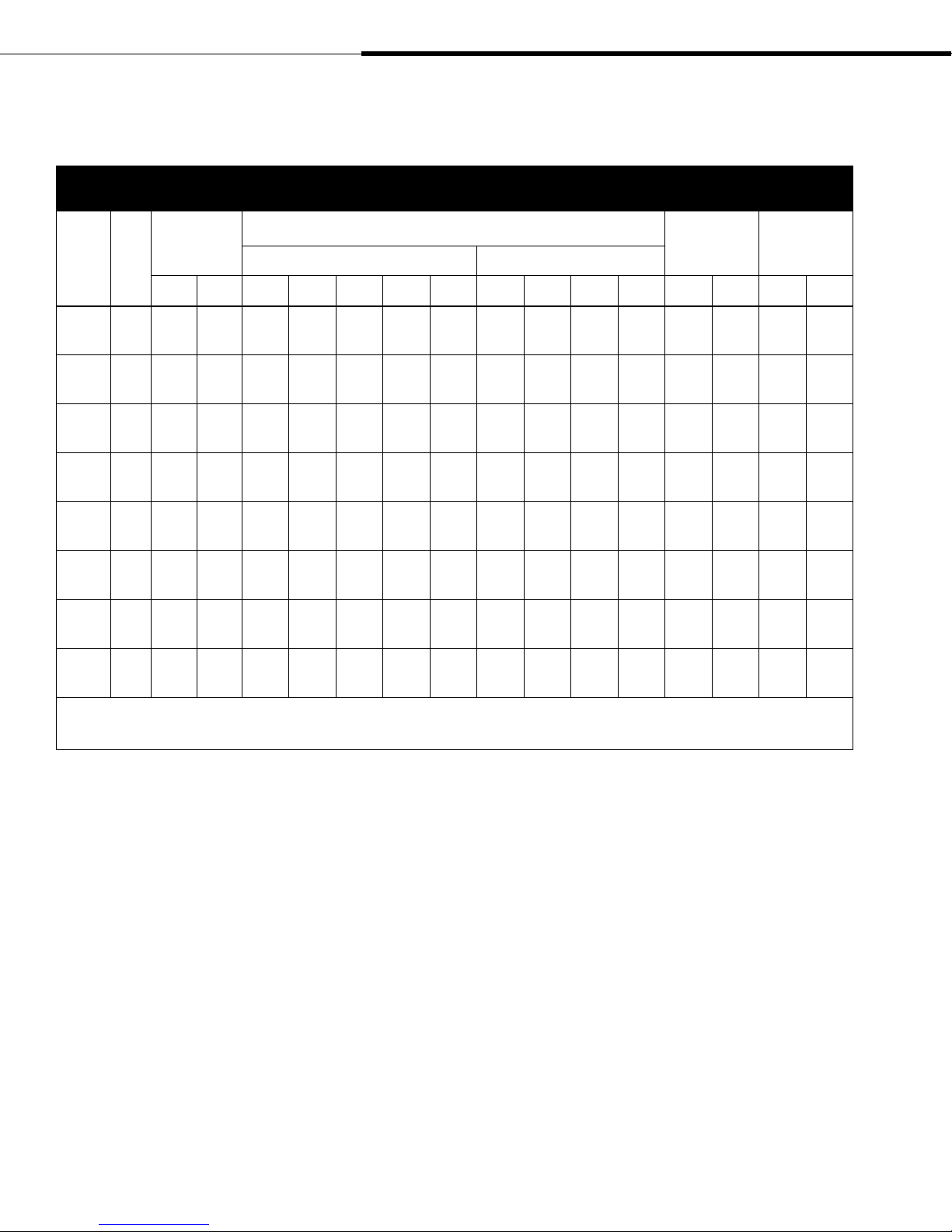
Table 2-1:
XT Series humidifier specifications
Installation: Specifications
Model
number kW
XT-10 3.4 10 4.5 16.2 14.0 12.2 7.0 5.6 9.4 8.1 4.1 3.2 27.6 12.5 29.8 13.5
XT-20 6.7 20 9.1 32.2* 27.9* 24.2 14.0 11.2 18.6 16.1 8.1 6.4 29.8 13.5 38.6 17.5
XT-30 10.1 30 13.6 —————28.0 24.3 12.1 9.7 43.0 19.5 70.5 32
XT-50 16.8 50 22.7 —————46.6 40.4 20.2 16.2 43.0 19.5 70.5 32
XT-75 25.1 75 34.0 ———————30.3 24.2 65.0 29.5 114.6 52
XT-100 33.5 100 45.4 ———————40.4 32.3 67.2 30.5 116.8 53
XT-150 50.3 150 68.0 ———————
XT-200 67.0 200 90.7 ———————
Maximum
steam capacity
lbs/hr kg/h 208V 240V 277V 480V 600V 208V 240V 480V 600V lbs kg lbs kg
Single-phase Three-phase
Current draw (amps)
2 ×
30.3**
2 ×
40.4**
2 ×
24.2**
2 ×
32.3**
Shipping
weight
137.8 62.5 242.5 110
142.2 64.5 246.9 112
Maximum
operating
weight
Note:
* For these models, shipping weight = 43 lbs (19.5 kg) and maximum operating weight = 70.5 lbs (32 kg)
** Double units require two circuits.
Page 2 • DRI-STEEM XT Series Electrode Steam Humidifier Installation, Operation, and Maintenance Manual
Page 5
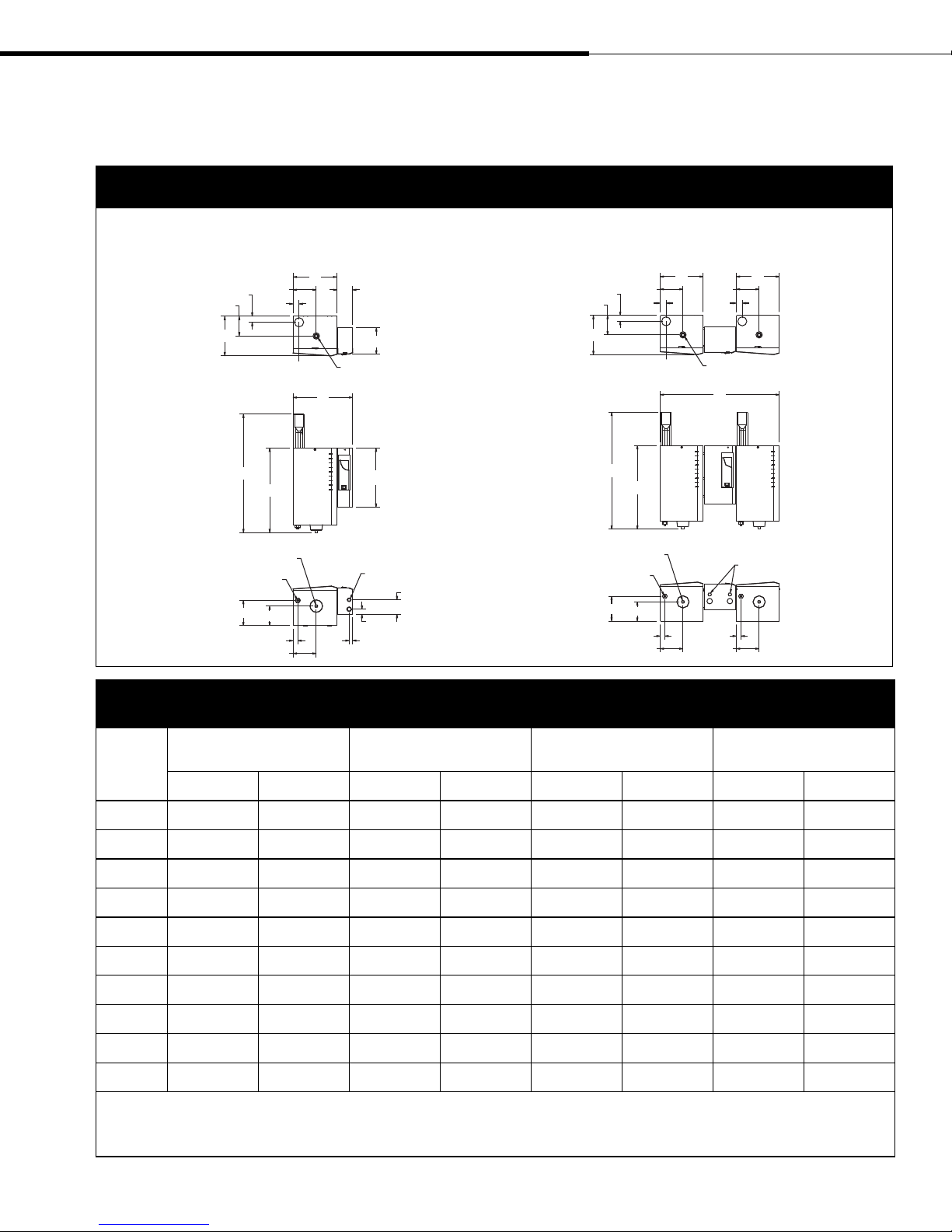
Installation: Dimensions
Figure 3-1:
Dimensions
Models XT-10, XT-20, XT-30, XT-50, XT-75, XT-100 Models XT-150, XT-200
Top view
1.8"
F
C
Front view
Bottom view
Water fill line connection
E
1.8"
K*
B
Drain
J
H
1.4"
G
Table 3-1:
Dimensions by model number
D
Dispersion outlet
A
4.5"
7.8"
17.4"
Electrical knockouts
4.3"
1.5"
1"
OM-7374
Top view
Front view
Bottom view
1.8"
1.8"
F
C
K*
B
Drain
Water fill line
connection
J
H
1.4" 1.4"
D
E
Dispersion outlet
G
D
E
1.8"
A
Electrical knockouts
G
OM-7419
XT-10
Callout
A 14.5 368 17.4 442 18.9 480 38.9 988
B 22.9 581 24.9 632 26.9 683 26.9 683
C 8.4 213 11.7 297 14.3 363 14.3 363
D 10.0 254 12.8 325 14.4 366 14.4 366
E 5.5 140 6.9 175 7.3 185 7.3 185
F 4.0 102 5.8 147 6.8 173 6.8 173
G 5.5 140 6.9 175 7.3 185 7.3 185
H 4.0 102 5.8 147 6.8 173 6.8 173
J 4.0 102 7.5 191 8.8 224 8.8 224
K 32.9 836 34.9 886 36.9 937 36.9 937
Note:
* Dimension K includes 10" (254 mm) for a fill cup extension. A fill cup extension is a required component when the humidifier is connected to a Rapid-sorb or Ultra-sorb dispersion
assembly or when the maximum developed length of piping/hose from humidifier to dispersion assembly/blower is more than 20' (6 m).
** XT-20 models using 208V single-phase power or 240V single-phase power have dimensions equal to Models XT-30 and XT-50.
XT-20**
inches mm inches mm inches mm inches mm
DRI-STEEM XT Series Electrode Steam Humidifier Installation, Operation, and Maintenance Manual • Page 3
XT-30
XT-50
XT-75
XT-100
XT-150
XT-200
Page 6
Choosing a location
Important:
Install humidifier only in locations that meet
the following temperature and relative
humidity (RH) requirements:
Maximum ambient temperature:
104
Minimum ambient temperature:
41
Maximum ambient humidity:
80% RH (non-condensing)
Note:
To open the humidifier electrical access door,
rotate the screw counter-clockwise ¼ turn.
The door pivots toward the front of the unit
from the bottom of the door. To close the
electrical access door, position screw slot so
that it is horizontal and then push the door
shut. Make sure sides of painted door go
outside stainless steel enclosure.
To open the humidifier steam cylinder access
door, rotate the screw counter-clockwise ¼
turn, lift door out of position, and remove
ground wire. Replace door in reverse order
of these instructions.
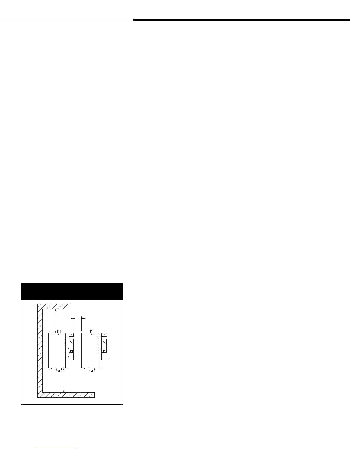
Figure 4-1:
Recommended minimum clearances
°F (40 °C)
°F (5 °C)
Choosing a location for the humidifier
When selecting a location for the humidifier, consider the following:
•
Proximity to duct
Install the humidifier near the air duct system where the
dispersion assembly will be located. The maximum recommended
length for vapor hose connecting a single humidifier to a
dispersion assembly is 10' (3 m). The maximum recommended
developed length for tubing or pipe connecting a single
humidifier to a dispersion assembly is 20' (6 m). See the
dispersion section of this manual for more information about
installing dispersion assemblies.
• Elevation of the installed dispersion assembly
The recommended installation location for the dispersion
assembly is at an elevation higher than the humidifier. However,
if the dispersion assembly must be installed at an elevation
lower than the humidifier, install a drip tee and drain as shown
in Figure 24-1. Before installing a dispersion assembly or
interconnecting piping, review all pitch requirements in the
dispersion section of this manual.
•
Required clearances (see Figure 4-1)
•
Electrical connections
Electrical power supply connections are made at the bottom panel
corner of the electrical enclosure. The system wiring is inside
the cover of the control cabinet. See the field wiring instructions
starting on Page 11.
• Supply water and drain piping connections
Water supply piping connections are made on the bottom left
side of the unit. Drain piping connections are made at the bottom
center of unit. See the field piping illustration and instructions
starting on Page 8.
• Exterior wall insulation
Do not install the humidifier on an exterior wall unless that wall
is properly insulated.
Top: 16"
(400 mm)
Side: 4" (100 mm)
Floor: 16" (400 mm)
Page 4 • DRI-STEEM XT Series Electrode Steam Humidifier Installation, Operation, and Maintenance Manual
Between units:
4" (100 mm)
Front:
36"
(914 mm)
OM-7359
Choosing a location for the dispersion assembly and control
devices
See Page 20 for recommended installation locations for the
dispersion assembly. See Page 13 for recommended installation
locations for control devices such as humidistats and transmitters.
Page 7

Mounting the humidifier
Figure 5-1:
Mounting keyhole locations by model number
Models XT-10, XT-20, XT-30, XT-50, XT-75, XT-100 Models XT-150, XT-200
A
WARNING!
Mount humidifier per the instructions in this
manual and to a structurally stable surface.
Improper mounting of humidifier may cause
the humidifier to fall off the wall resulting in
severe personal injury or death.
A
G
D
A
D
C
E
B
F
OM-7360
D
Table 5-1:
Mounting dimensions
XT-10
XT-20*
inches mm inches mm inches mm inches mm
A 3.9 99 7.1 180 7.5 191 7.5 191
XT-30
XT-50
XT-75
XT-100
XT-150
XT-200
C
C
E
B
F
OM-7420
B 14 356 16.3 414 19.1 485 19.1 485
C 3.1 79 3.6 91 3.4 86 3.4 86
D 3 76 2.1 53 3.4 86 3.4 86
E 2.8 71 3 76 2.8 71 2.8 71
F 3.8 97 3.2 81 2.6 66 2.6 66
G — — — — — — 17.1 434
Note:
* XT-20 models using 208V single-phase power or 240V single-phase power have
dimensions equal to Models XT-30 and XT-50.
DRI-STEEM XT Series Electrode Steam Humidifier Installation, Operation, and Maintenance Manual • Page 5
Page 8

WARNING!
Mount humidifier per the instructions in this
manual and to a structurally stable surface.
Improper mounting of humidifier may cause
the humidifier to fall off the wall resulting in
severe personal injury or death.
Mounting the humidifier (continued)
Prepare humidifier for mounting
Unpack unit from shipping carton and remove steam cylinder door.
Disconnect electrode and high water sensor connectors from steam
cylinder. Pull pins from brackets that retain steam cylinder. Remove
steam cylinder from drain valve body.
Mount humidifier
Mount the humidifier so that it is plumb. See Figures 8-1 and 9-1
for an installation overview.
When mounting on a wood stud wall (studs 16" [406 mm] on
center), locate studs and attach spanner board so that each of the
screws centers on a stud. Mark hole locations per Table 5-1 and
predrill 1/8" (3 mm) diameter pilot holes. Secure cabinet to spanner
board with screws provided.
When mounting on a metal stud wall, locate the studs (16"
[406 mm] on center) and drill a ¼" (6 mm) hole through the studs
and wall. Mount spanner board with ¼" (6 mm) bolts through the
wall, studs, and a backing plate on the backside of the wall and
secure with a nut and washer.
If 16" (406 mm) on-center studs are not available, mount spanner
boards on the wall, spanning two studs. If two horizontal boards
are used, locate one at the top of the cabinet for the mounting
screws and the other board located 3.5" (89 mm) on center from the
bottom of the cabinet.
For hollow block or poured concrete wall mounting, mark
mounting holes per Table 5-1. Drill pilot holes sized for the proper
concrete anchors. Secure cabinet in place using four screws.
Page 6 • DRI-STEEM XT Series Electrode Steam Humidifier Installation, Operation, and Maintenance Manual
Page 9
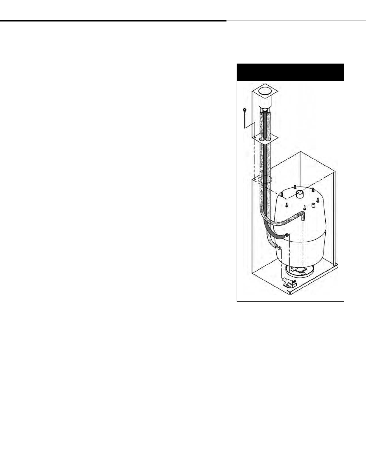
Fill cup extension installation
Install fill cup extension kit (if applicable)
A fill cup extension kit is required with all Rapid-sorb and
Ultra-sorb dispersion assemblies or when the maximum developed
length of piping/hose from humidifier to dispersion assembly/
blower is more than 20' (6 m).
1. Remove hose clamps attached to fill cup extension bracket.
2. Remove Phillips screw near large opening on top enclosure and
retain for use in Step 4.
3. Feed tubes through left rear opening on top of steam cylinder
enclosure.
4. Mount bracket with screw from Step 2 (see Figure 7-1).
5. Slip smaller hose clamp (D18) from Step 1 over smaller diameter
hose and slide open end of hose onto fill valve body connection.
Tighten hose clamp.
6. Slip larger hose clamp (D21) from Step 1 over larger diameter
hose (the one attached to cone bottom of fill cup) and slide open
end of hose onto drain valve body connection. Tighten hose
clamp.
7. Place overflow tube with elbow into hole of drain cup plate.
Replace steam cylinder
1. Slide steam cylinder (with warning label facing toward operator)
into drain valve body while making sure side tabs engage
brackets.
2. Reconnect electrode and high water sensor connectors to steam
cylinder (refer to unit wiring diagram located in electrical
enclosure).
Figure 7-1:
Fill cup extension installation
DRI-STEEM XT Series Electrode Steam Humidifier Installation, Operation, and Maintenance Manual • Page 7
OM-7385
Page 10
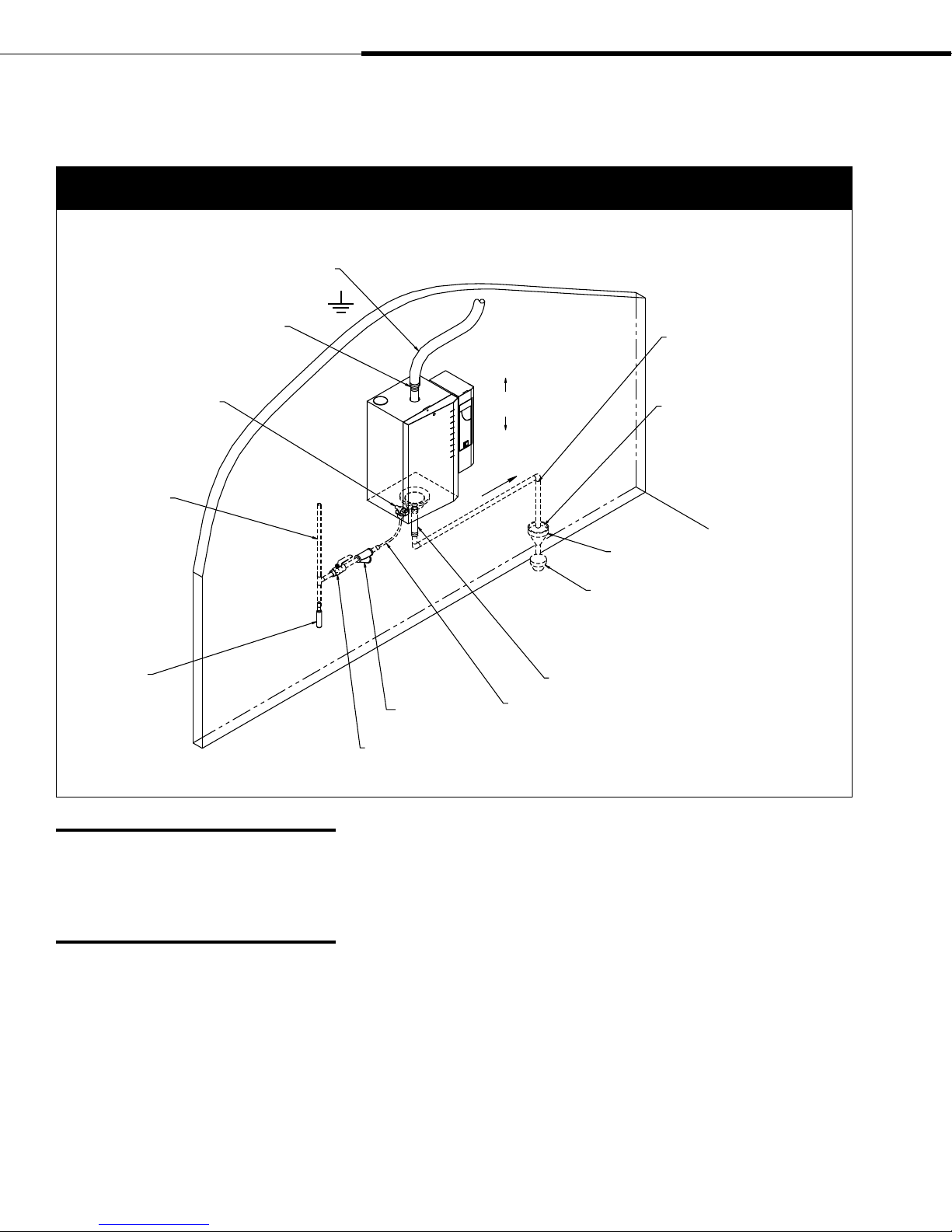
Supply water and drain piping
Figure 8-1:
Field piping overview for models XT-10, XT-20, XT-30, XT-50, XT-75, and XT-100
Steam vapor hose; may also use tubing or
pipe. See Table 22-1 for maximum piping
lengths. Tubing or pipe must be grounded.
Fill valve (with screen)
Continuous copper
water supply line;
water pressure must
be between 25 psi
and 80 psi (175 kPa
and 550 kPa)
Shock arrester
recommended
to reduce water
hammer, by installer
Adapter
Pitch 1/8”/ft (1%)
Inlet strainer,
by installer
Supply valve, by installer
¾" (DN20) metallic drain piping. If
piping run is over 10' (3 m) increase
pipe to 1¼" (DN32).
Install plumb
towards drain
Spill funnel. Plumb to floor drain
Refer to governing codes for drain pipe size and
maximum discharge water temperature. Offset
humidifier from spill funnel to prevent flash steam
from rising into the humidifier.
Hose and clamps
3/8" (DN10) O.D. copper; compression fitting on fill valve
1" (25 mm) air gap required
WARNING!
Drain piping surface may be hot. Touching
or contact with hot pipe may cause severe
personal injury.
Page 8 • DRI-STEEM XT Series Electrode Steam Humidifier Installation, Operation, and Maintenance Manual
OM-7362
Supply water quality
XT Series humidifiers use normal tap water or softened water to
generate humidification steam. Water conductivity must be within
the range of 125 to 1250 μS/cm (which, in many cases, is roughly
equivalent to 3.4 to 36.3 grains/gallon). Demineralized water cannot
be used because it is not conductive. Do not use heated supply water
because unheated supply water is required for drain water tempering.
Page 11
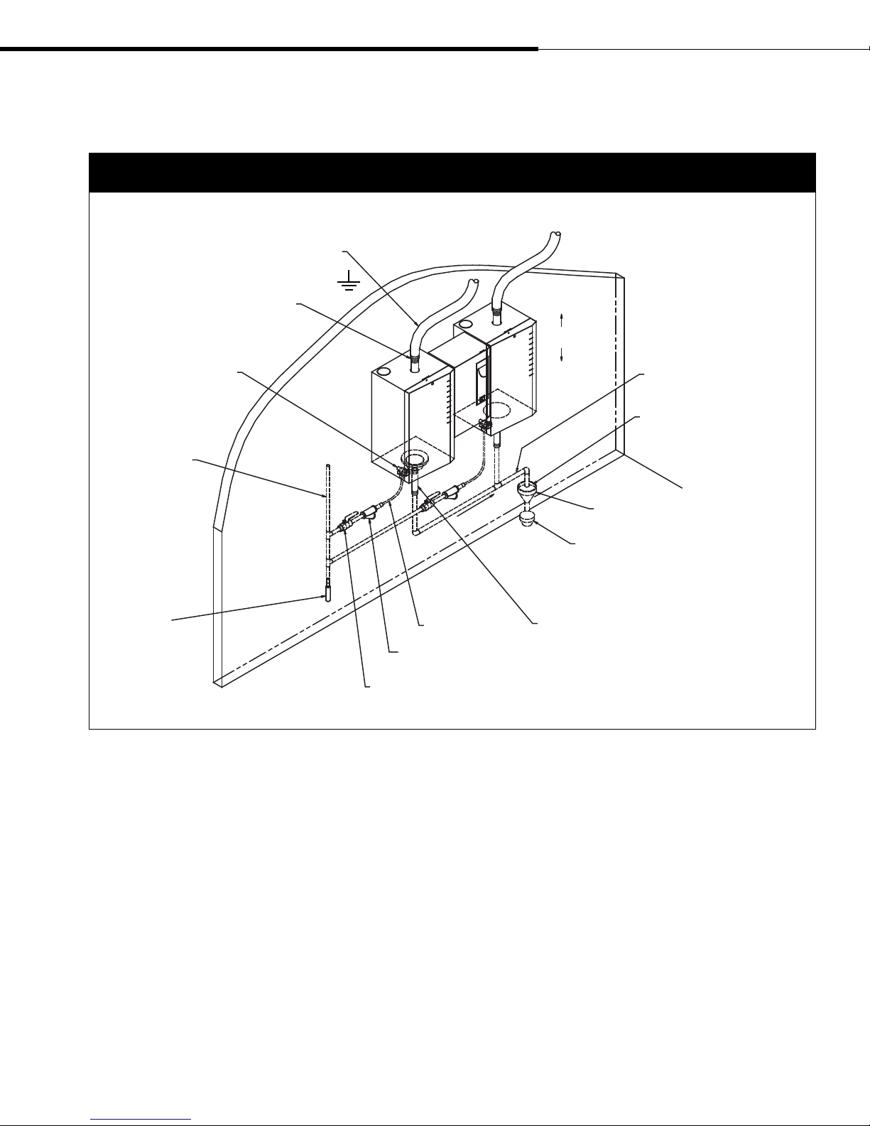
Supply water and drain piping
(continued)
Figure 9-1:
Field piping overview for Models XT-150 and XT-200
Steam vapor hose; may also use tubing or
pipe. See Table 22-1 for maximum piping
lengths. Tubing or pipe must be grounded.
Adapter
Install plumb
Fill valve (with screen)
Continuous copper
water supply line;
water pressure must
be between 25 psi
and 80 psi (175 kPa
and 550 kPa)
Shock arrester
recommended
to reduce water
hammer, by installer
Inlet strainer,
by installer
Supply valve, by installer
Pitch 1/8”/ft (1%)
towards drain
3/8" (DN10) O.D.
copper; compression fitting
on fill valve
Supply water piping
Use only copper for supply water piping—do not use rubber or
plastic. A strainer is recommended to be installed in the supply
piping before the fill valve. The fill valve connection size is a 3/8"
(DN10) compression fitting. In cases where water hammer may be a
possibility, consider installing a shock arrestor. Water pressure must
be between 25 psi and 80 psi (175 kPa and 550 kPa).
¾" (DN20) metallic drain piping up
to second drain connection, then
increase pipe to 1¼" (DN32)
1" (25 mm) air gap required
Spill funnel. Plumb to floor drain
Refer to governing codes for drain pipe size and
maximum discharge water temperature. Offset
humidifier from spill funnel to prevent flash steam
from rising into the humidifier.
Hose and clamps
OM-7362
Important: Thoroughly flush the
supply water piping to remove pipe residue
and stagnant water before connecting
piping to the humidifier. Pipe residue and
stagnant water in the water supply piping
can cause the humidifier to not reach
required steam capacity.
DRI-STEEM XT Series Electrode Steam Humidifier Installation, Operation, and Maintenance Manual • Page 9
Page 12
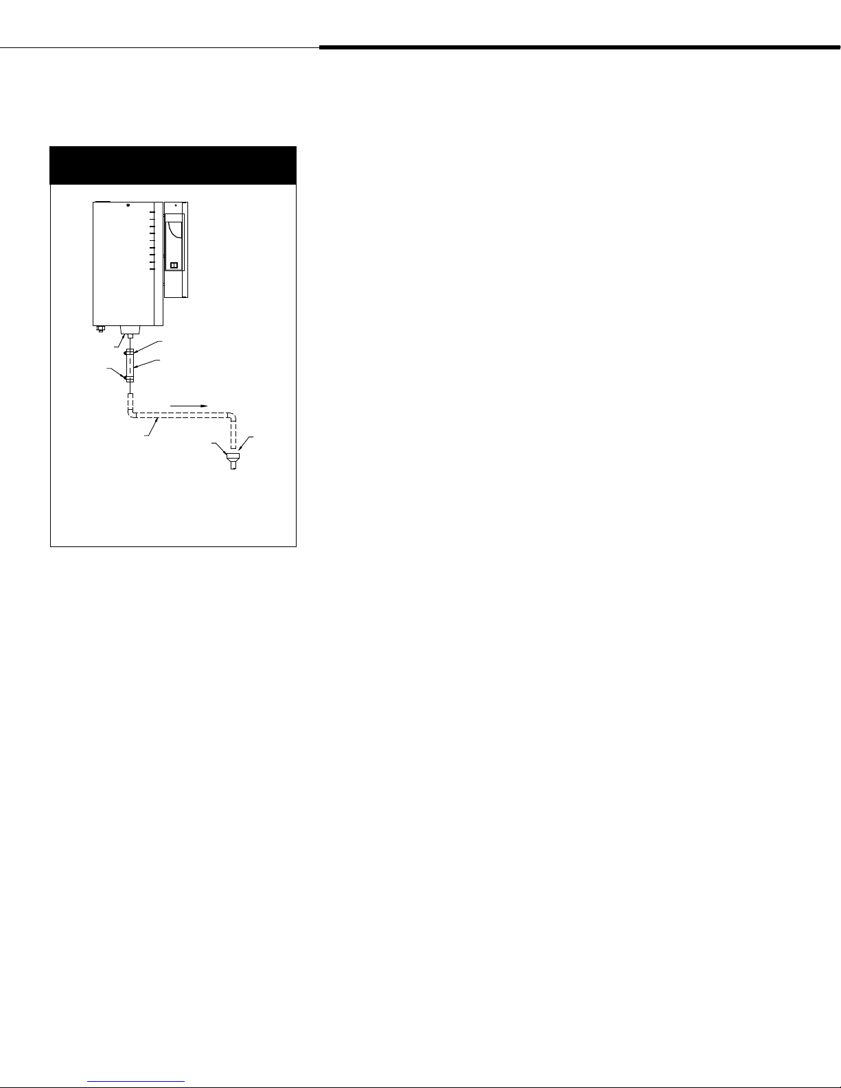
Supply water and drain piping
(continued)
Figure 10-1:
Drain piping detail
Drain cup
Hose clamp
(field supplied)
¾" (DN20) copper
Note:
* A D29 bolt hose clamp and black rubber hose
ship with each humidifier. These parts can also be
ordered from DRI-STEEM. See the replacement parts
section of this manual for part numbers.
D29 bolt hose clamp
Black rubber hose
Pitch 1/8”/ft (1%)
towards drain
Open drain
1"
(25 mm)
air gap
OM-7379
Humidifier drain piping
Drain piping must be code-approved copper or steel rated for 212 °F
(100 °C) minimum. The final connection size is ¾" (DN20) copper
for the steam cylinder drain. Do not reduce this connection size.
See Figures 8-1 and 9-1 for typical installation dimensions and
requirements.
If drainage by gravity is not possible, use a reservoir pump rated for
212 °F (100 °C) water.
A 10" (254 mm) piece of hose is provided to function as the flexible
connection from the drain cup to the field installed drain plumbing.
A D29 hose clamp is provided to secure the drain hose to the drain
cup.
See Figure 10-1 for drain piping detail.
If the equivalent length of pipe from the humidifier drain to the
plumbing system drain is more than 10' (3 m), increase the pipe size
to 1¼" (DN32).
Page 10 • DRI-STEEM XT Series Electrode Steam Humidifier Installation, Operation, and Maintenance Manual
Page 13
Field wiring
Humidifier field wiring
All wiring must be in accordance with all governing codes and
with the unit wiring diagram. The unit wiring diagram is inside the
electrical control cabinet. Power supply wiring must be rated for
105 °C.
When selecting a location for installing the humidifier, avoid
areas close to sources of electromagnetic emissions such as power
distribution transformers.
Do not loop power wiring.
Do not use aluminum wire.
Field wiring connections and requirements
Conduit knockouts are provided on the bottom of the electrical
control cabinet. Control wiring knockouts are on the bottom front;
power wiring knockouts are on the bottom rear.
CAUTION! Adding alternate conduit connections is not
recommended; however, if making holes and knockouts in the
humidifier cabinet, protect all internal components from debris
and vacuum out cabinet when finished. Failure to comply with this
caution can damage sensitive electronic components and void the
DRI-STEEM warranty.
WARNING!
Only qualified electrical personnel should
perform field wiring installation procedures.
Improper wiring or contact with energized
circuits may cause property damage, severe
personal injury, or death as a result of
electric shock and/or fire.
d
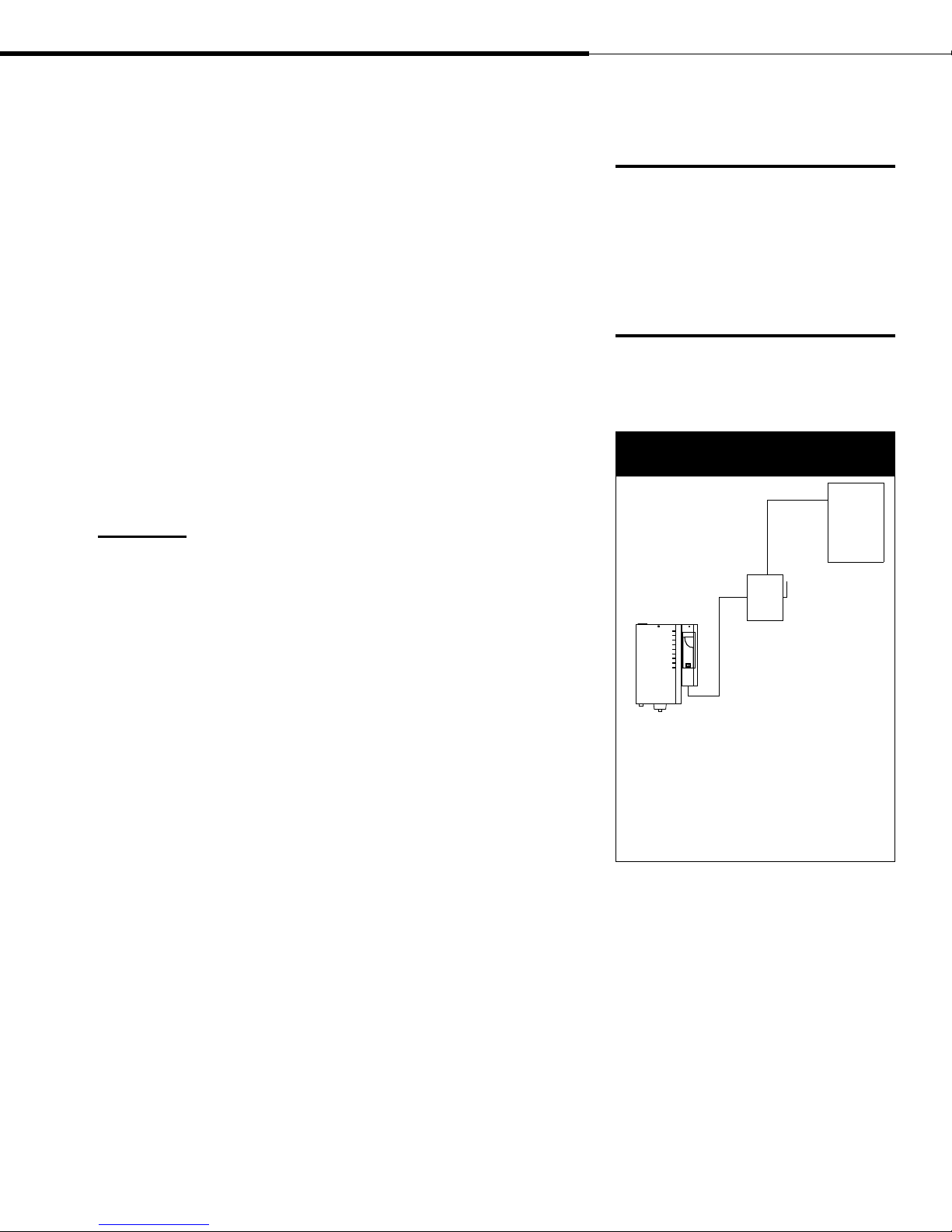
Figure 11-1:
Field wiring requirements
Power
supply
Fused
disconnect
Humidifier
Control component placement
Follow the guidelines on Page 13 for placing humidistats,
transmitters, and airflow proving switches.
More on the next page ▶
OM-7363
Notes:
• Control wiring and power wiring must be run
in dedicated or separate earthed metal conduit,
cable trays, or trunking.
• Separate the line voltage wiring from low voltage
control circuit wiring when routing electrical
wiring inside the humidifier cabinet.
• Do not use chassis or safety grounds as currentcarrying commons. Never use a safety ground as a
conductor or neutral to return circuit current.
DRI-STEEM XT Series Electrode Steam Humidifier Installation, Operation, and Maintenance Manual • Page 11
Page 14

Field wiring (continued)
Proper wiring prevents electrical noise.
Electrical noise can produce undesirable
effects on electronic control circuits, which
affects controllability. Electrical noise is
generated by electrical equipment such as
inductive loads, electric motors, solenoid
coils, welding machinery, or fluorescent light
circuits. The electrical noise or interference
generated from these sources (and the
effect on controllers) is difficult to define,
but the most common symptoms are erratic
control or intermittent operational problems.
Important:
• For maximum EMC effectiveness, wire all
humidity, high limit, and airflow controls
using multicolored shielded/screened
plenum-rated cable with a drain wire for
the shield/screen. Connect the drain wire
to the shield/screen ground terminal with
wire less than 2" (50 mm) in length.
• Do not ground shield at the device end.
Below are field wiring connection instructions:
•
Connect to line power.
Refer to the wiring diagram or the data plate on the outside of the
cabinet for wire sizing amperage.
•
Connect to control signal wiring
from a humidistat, transmitter, or signal by others. See the control
wiring diagrams on pages 14-19.
•
Connect remote signal wiring.
When wired to a remote signaling device, two relays indicate
if there is a fault with draining, filling, or water level control
functions of the humidifier, or if a required maintenance interval
has been reached. See the control wiring diagrams on pages
14-19. To enable the remote signaling device, connect wiring
to control terminals 9 (N.O.), 10 (N.C.), 11 (C) for Relay 1, and
connect wiring to control terminals 26 (N.O.), 27 (N.C.), and 28
(C) for Relay 2.
•
Connect to the duct airflow proving switch and duct high limit
humidistat wiring (recommended optional devices). If not used,
jumper H-H terminals unless on/off humidistat is installed.
WARNING!
DRI-STEEM strongly recommends installing a duct airflow proving
switch and a duct high limit humidistat. These devices prevent the
humidifier from making steam when there is no airflow in the duct or
when the RH level in the duct is too high. Failure to install these devices
can result in excessive moisture in the duct, which can cause bacteria
and mold growth or dripping through the duct.
Grounding requirements
A safety grounding system that meets national, state, and local
electrical codes is required. The ground connection must be made
with solid metal to metal connections. Ground wire should be the
same size as power wiring.
Control input wiring
XT Series humidifiers accept RH or demand signals from
DRI-STEEM control components or from a signal by others. For
wiring connection requirements, first determine which control
scenario applies. Then, refer to the corresponding control input
wiring diagram shown on the following pages, or located inside the
accessory box.
Page 12 • DRI-STEEM XT Series Electrode Steam Humidifier Installation, Operation, and Maintenance Manual
Page 15
Humidistat and transmitter
placement
Humidistat and transmitter locations are critical
Humidistat or transmitter location has a significant impact on
humidifier performance. In most cases, it is recommended that you
do not interchange duct and room humidity devices. Room humidity
devices are calibrated with zero or little airflow; whereas duct humidity
devices require air passing across them. Recommended humidistat and
transmitter locations (see Figure 13-1):
A This is the ideal sensing location because this placement ensures the
best uniform mix of dry and moist air with stable temperature control.
B This location is acceptable, but the room environment may affect
controllability such as when the humidistat or transmitter is too close
to air grilles, registers, or heat radiation from room lighting.
C This location is acceptable because it provides a good uniform
mixture of dry and moist air, but if an extended time lag exists
between moisture generation and sensing, make sure the control
contractor extends the sampling time.
D This location behind a wall or partition is acceptable for sampling
the entire room if the sensor is near an air exhaust return outlet. This
location is also typical of humidistat or transmitter placement for
sampling a critical area.
E These locations are not acceptable because they may not represent
actual overall conditions in the space.
F These locations are not acceptable. Do not place humidistats or
transmitters near windows, door passageways, or areas of stagnant
airflow.
G This is the best location for a duct high limit humidistat or humidity
transmitter.
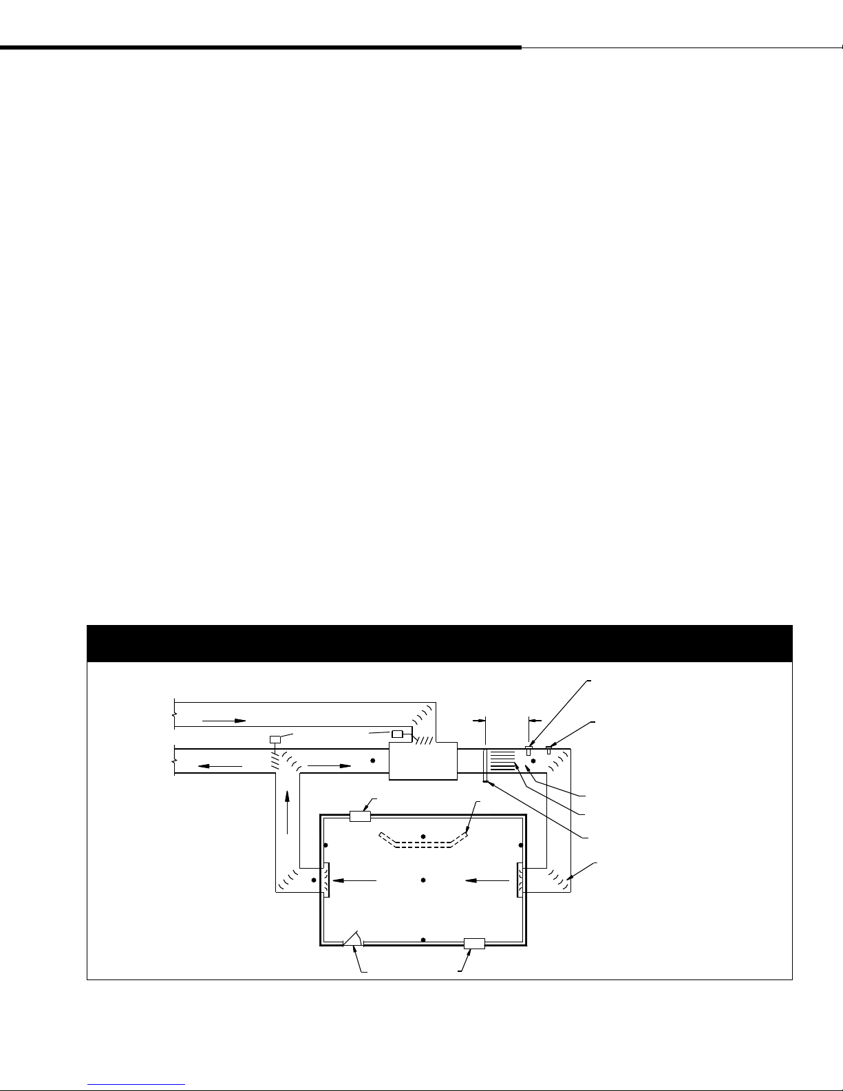
Figure 13-1:
Recommended humidistat and transmitter locations
Outside air
Damper control
Relief air
Return air
A
C
Window
E
F
Doorway
(2.4 m to 3.7 m)
minimum
AHU
Wall or
partition
D
B
EF
Window
8' to 12'
F
High limit humidistat or high limit transmitter
(set at 90% RH maximum) for VAV applications
Airflow switch or differential pressure
switch (sail type recommended for VAV
applications)
G
Vapor absorption has taken place
Point of vapor absorption
Humidifier dispersion assembly
Turning vanes
DC-1084M
DRI-STEEM XT Series Electrode Steam Humidifier Installation, Operation, and Maintenance Manual • Page 13
Page 16
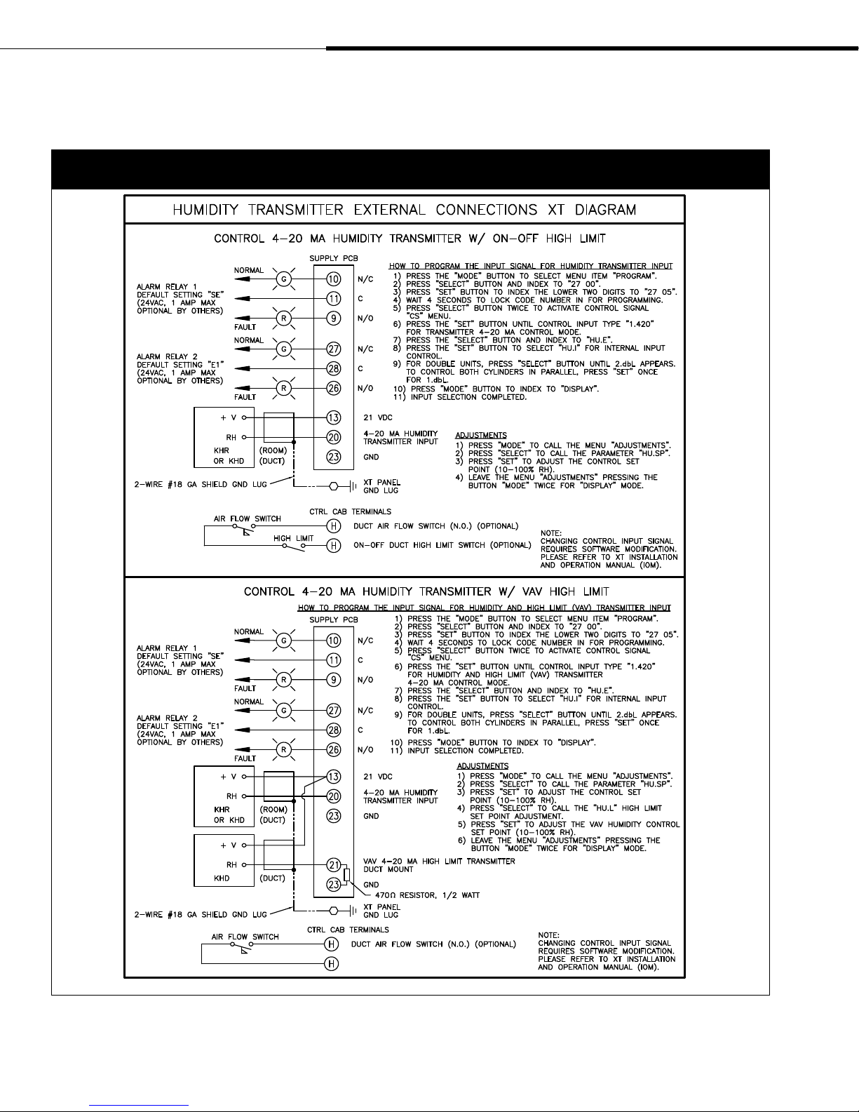
Wiring diagrams
Figure 14-1:
Control wiring diagrams for humidity transmitter external connections to XT Series humidifiers
Page 14 • DRI-STEEM XT Series Electrode Steam Humidifier Installation, Operation, and Maintenance Manual
Page 17
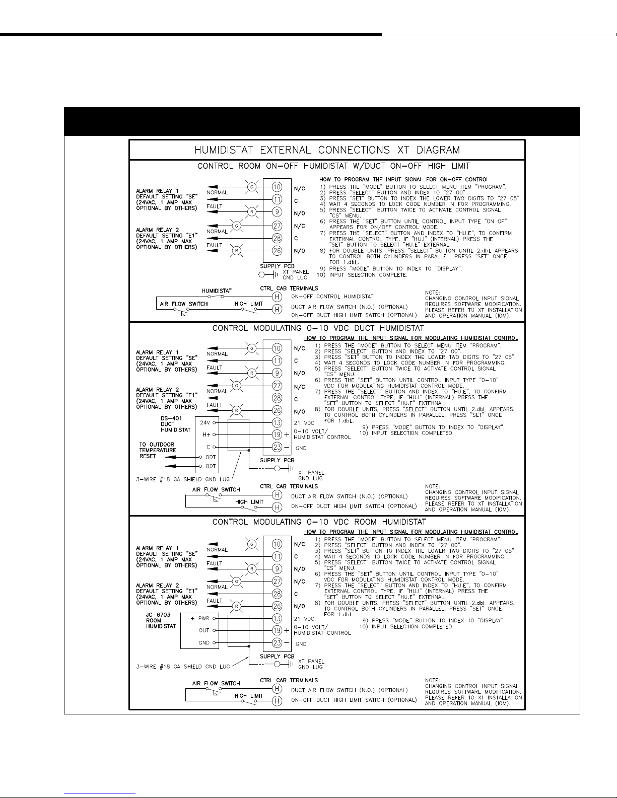
Wiring diagrams (continued)
Figure 15-1:
Control wiring diagrams for humidistat external connections to XT Series humidifiers
DRI-STEEM XT Series Electrode Steam Humidifier Installation, Operation, and Maintenance Manual • Page 15
Page 18
Wiring diagrams (continued)
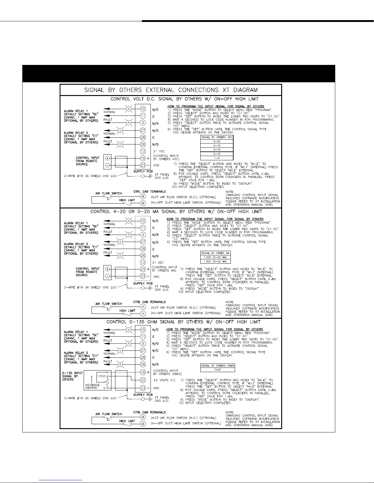
Figure 16-1:
Control wiring diagrams for signal by others external connections to XT Series humidifiers
Page 16 • DRI-STEEM XT Series Electrode Steam Humidifier Installation, Operation, and Maintenance Manual
Page 19
Wiring diagrams (continued)
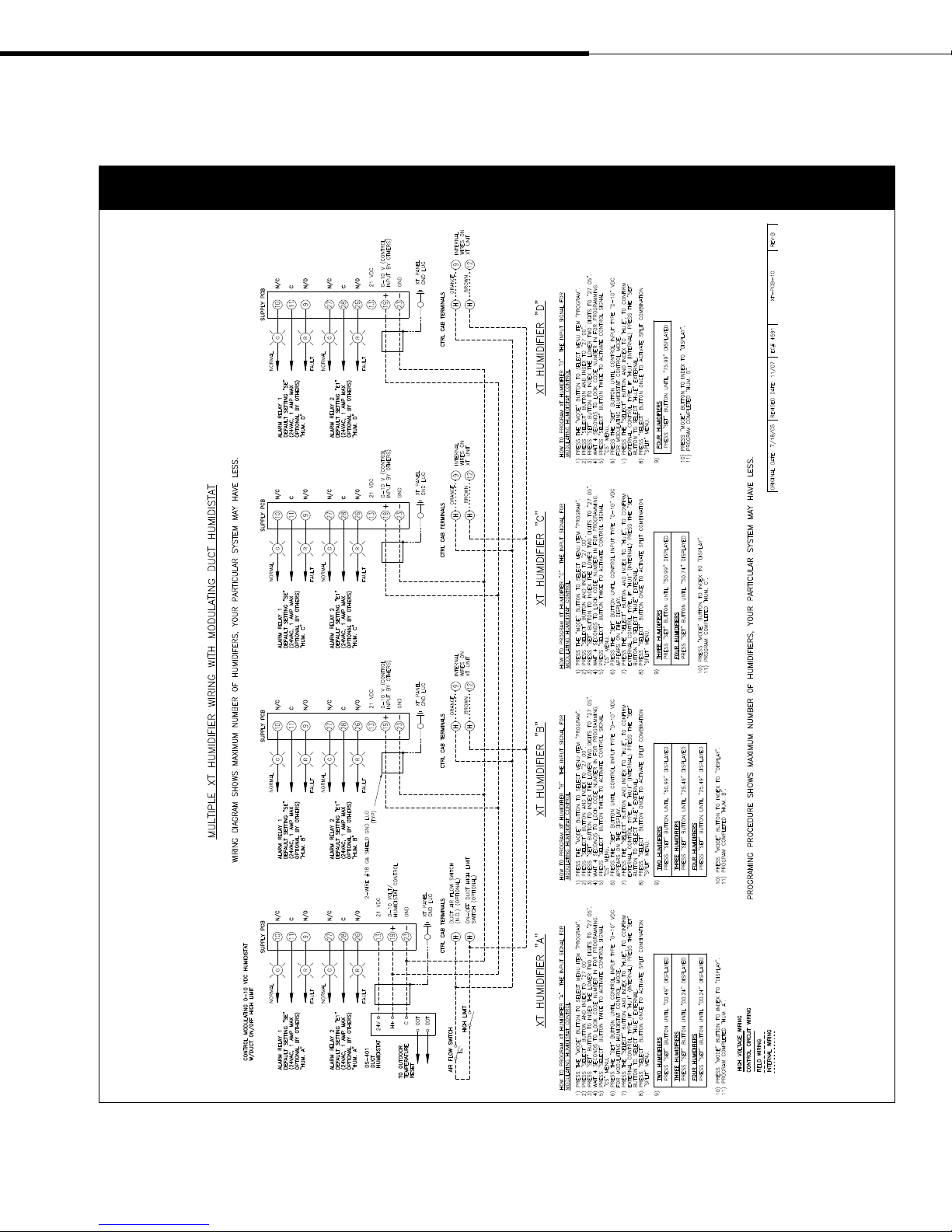
Figure 17-1:
Wiring diagram for sequenced XT Series humidifiers with a modulating duct humidistat
DRI-STEEM XT Series Electrode Steam Humidifier Installation, Operation, and Maintenance Manual • Page 17
Page 20
Wiring diagrams (continued)
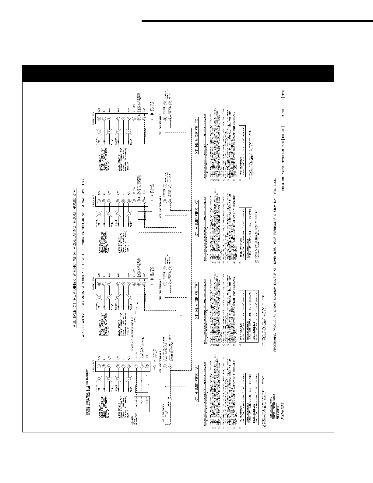
Figure 18-1:
Wiring diagram for sequenced XT Series humidifiers with a modulating room humidistat
Page 18 • DRI-STEEM XT Series Electrode Steam Humidifier Installation, Operation, and Maintenance Manual
Page 21

Wiring diagrams (continued)
Figure 19-1:
Wiring diagram for sequenced XT Series humidifiers with a modulating 0-10 VDC signal by others
DRI-STEEM XT Series Electrode Steam Humidifier Installation, Operation, and Maintenance Manual • Page 19
Page 22

Dispersion: General instructions
Where to find more dispersion
information
In this document:
• Interconnecting piping and drip tee
installation, pages 21-24
• Single Tube and Multiple Tube installation
instructions, pages 25-28
• Rapid-sorb
pages 29-35
• XT Steam Blowers, pages 36-43
On our web site:
The following documents can be viewed,
printed or ordered from our web site,
www.dristeem.com
• Catalogs (which include dispersion
nonwetting distance graphs):
– XT Series Humidifier
– Ultra-sorb
• Installation, Operation, and Maintenance
manuals:
– Ultra-sorb
DRI-STEEM Design Guide
•
loss tables and general humidification
information)
On Dri-calc:
Dri-calc
sizing and selection software, and may be
ordered at our web site, www.dristeem.com.
Included in Dri-calc:
®
installation instructions,
®
(includes steam
®
is our humidification system
Selecting the dispersion assembly location
• For each dispersion device, DRI-STEEM documents distances
required for absorption to occur. If you have questions about
absorption distances, see the absorption tables in the XT Series
catalog, available for viewing, printing or ordering at
www.dristeem.com
• It is important that the dispersion assembly be positioned where
the water vapor being discharged is carried off with the airstream
and is absorbed before it can cause condensation or dripping in
the duct.
• In general, the dispersion assembly is best placed where the
air can most readily absorb the moisture being added without
causing condensation at or after the unit. This normally will be
after the heating coil or where the air temperature is highest.
• Place the dispersion assembly such that absorption will occur
before the intake of a high efficiency filter. The filter can remove
the visible moisture and become waterlogged.
• Place the dispersion assembly such that absorption will occur
before coming in contact with any metal surface.
• Place the dispersion assembly such that absorption will occur
before fire or smoke detection devices.
• Place the dispersion assembly such that absorption will occur
before a split in the duct. Otherwise, the dispersion assembly may
direct more moisture into one duct than the other.
• When draining dispersion condensate to an open drain, provide
a 1" (25 mm) gap between the condensate drain piping and the
drain. Locate air gap only in spaces with adequate temperature
and air movement to absorb flash steam, or condensing on nearby
surfaces may occur.
• A comprehensive library of installation
guide documents, including:
– Rapid-sorb installation instructions
for vertical airflows
– Recommended dispersion placement
within a duct or air handler
Or call us at 800-328-4447
While obtaining documents from our web
site or from Dri-calc is the quickest way to
review our literature, we'd also be happy to
mail to you any literature you need.
Page 20 • DRI-STEEM XT Series Electrode Steam Humidifier Installation, Operation, and Maintenance Manual
IMPORTANT:
Failure to follow the recommendations in this section can result
in excessive back pressures on the humidifier. This will result in
unacceptable humidification system performance such as water
siphoning from the steam cylinder, blown water seals, erratic water
level control, and spitting condensate from the dispersion tube(s).
Page 23

Dispersion: Interconnecting piping
requirements
Connecting humidifier to dispersion assembly with vapor hose
• Always support vapor hose to prevent sags or low spots.
• See the table on Page 26 for interconnecting tubing and pipe pitch
requirements for single tube and multiple tube applications. See
the table on Page 30 for interconnecting tubing and pipe pitch
requirements for Rapid-sorb applications.
• See the maximum steam carrying capacity table on the next page.
• Use DRI-STEEM vapor hose. Other manufacturers of vapor hose
may use unacceptable release agents or material mixes that can
affect humidifier system performance adversely. Using hose from
alternative manufacturers increases the possibility of foaming
in the steam cylinder. Foaming can cause water level control
inaccuracies and reduced steam production.
• Do not use vapor hose in outdoor applications.
• Do not insulate vapor hose. Insulation causes accelerated heat
aging, causing the vapor hose to become hard and susceptible to
failure due to cracks.
• The steam outlet on the humidifier is sized to the output of the
humidifier. DO NOT use hose with an inside diameter (ID)
smaller than the steam outlet.
• If the humidifier must be located above the dispersion assembly,
use the recommend installation as shown on Page 24.
• For Single Tube applications, see the hose kit sizing chart on
Page 25.
•
To avoid cracking the steam cylinder outlet, use the bolt hose
clamp when attaching white braided hose to the steam cylinder
(see Figure 21-1). Use the worm-drive hose clamp for clamping
white braided hose to the stainless steel adapter.
Connecting humidifier to dispersion assembly
with tubing or pipe
• See the table on Page 26 for interconnecting tubing and pipe pitch
requirements for single tube and multiple tube applications. See
the table on Page 30 for interconnecting tubing and pipe pitch
requirements for Rapid-sorb applications.
• The steam outlet on the humidifier is sized to the output of the
humidifier. DO NOT use interconnecting tubing or pipe with
an inside diameter (ID) smaller than 1½" (DN40). REDUCING
THE INSIDE DIAMETER OF THE INTERCONNECTING
PIPING WILL RESULT IN THE INTERNAL HUMIDIFIER
SYSTEM PRESSURE EXCEEDING THE PARAMETERS FOR
ACCEPTABLE PERFORMANCE.
• Hose cuff kits are available from DRI-STEEM to connect tubing
or pipe to the stainless steel adapter and the dispersion assembly.
• 90° elbows are not recommended; use two 45° elbows, 1' (0.3 m)
apart.
• Thin wall tubing heats up faster and causes less start-up loss than
heavy wall pipe.
More on the next page ▶
Figure 21-1:
Steam outlet connections
Vapor hose connection
Hose clamp
on vapor hose
(supplied with
hose kit)
Worm-drive
hose clamp*
Bolt hose
clamp*
Tubing or pipe connection
Tubing or pipe;
must ground
Hose cuff **
Worm-drive
hose clamp*
Bolt hose
clamp*
Notes:
* A stainless steel adapter, white braided hose, and
two hose clamps ship with each humidifier using
duct dispersion. Hose clamps shipped, by model:
– XT-10 and XT-20 (except XT-20 208/240/1-Ph):
¾" worm-drive clamp and D29 bolt clamp
– XT-20 208/240/1-Ph , XT-30, XT-50, and XT-75:
1¼" worm-drive clamp and D43 bolt clamp
See the replacement parts section of this manual for
part numbers.
** Hose cuffs and hose clamps can be ordered from
DRI-STEEM. One cuff and two clamps connect tubing
or pipe to the stainless steel adapter shown above,
and one cuff and two clamps connect tubing or pipe
to the dispersion assembly (not shown). Use 1.5"
× 6" cuffs (Part No. 305390-006) with 1.5" clamps
(Part No. 700560-150).
Stainless steel
adapter*
White braided hose*
Steam
cylinder
OM-7377
Hose clamp**
Hose clamp**
Stainless steel
adapter*
White braided
hose*
Steam
cylinder
OM-7378
DRI-STEEM XT Series Electrode Steam Humidifier Installation, Operation, and Maintenance Manual • Page 21
Page 24

Dispersion: Interconnecting piping
requirements (continued)
Connecting humidifier to dispersion assembly with tubing or
pipe (continued)
• Insulating hard pipe reduces the loss in output caused by
condensation.
• When using hard pipe, take care to remove ALL traces of residual
materials used to assemble the pipe. This will minimize the
possibility of foaming in the steam cylinder. Denatured alcohol or
mineral spirits work best for removing residual materials.
• If the humidifier must be located above the dispersion assembly,
use the recommend installation as shown on Page 24.
• See the maximum steam carrying capacity table below.
Table 22-1:
Maximum steam carrying capacity and length of interconnecting vapor hose, tubing, and pipe*
†††
Hose
Hose I.D. Maximum capacity Maximum length** Tube or pipe size*** Maximum capacity
Copper or stainless steel tubing
and Schedule 40 steel pipe
Maximum developed
length
†
inches DN lbs/hr kg/h ft m inches DN lbs/hr kg/h ft m
DRI-STEEM white braided hose ——————
7/82220 9 10 3 ——————
1-3/8 35 75 34 10 3 ——————
DRI-STEEM black vapor hose ——————
1½ 40 150 68 10 3 1½ 40 150 68 20 6
2 50 250 113 10 3 2 50 220 100 30 9
††
80
3
4†† 100
††
5
††
6
* Based on total maximum pressure drop in hose, tubing, or piping of 5" wc (1244 Pa)
** Maximum recommended length for vapor hose is 10' (3 m). Longer distances can cause kinking or low spots.
*** To minimize loss of capacity and efficiency, insulate tubing and piping.
†
Developed length equals measured length plus 50% of measured length to account for pipe fittings. If maximum developed length is more than 20' (6 m), a fill
cup extension kit is required.
††
Requires flange connection
†††
When using vapor hose, use DRI-STEEM vapor hose for best results. Field-supplied hose may have shorter life and may cause foaming in the evaporating
chamber resulting in condensate discharge at the dispersion assembly. Do not use vapor hose for outdoor applications.
125
150
††
††
††
††
450 204 80 24
750 340 100 30
1400 635 100 30
2300 1043 100 30
Page 22 • DRI-STEEM XT Series Electrode Steam Humidifier Installation, Operation, and Maintenance Manual
Page 25

Dispersion: Interconnecting piping
requirements (continued)
Figure 23-1:
Piping from steam cylinders to ducted dispersion assembly
Pitch 2"/ft (15% min.)
To dispersion
assembly
Worm-drive hose
clamp*
Bolt hose
clamp*
XT-100
Humidifier
Note:
* A stainless steel Y connector, two white braided hoses, and four
hose clamps ship with each XT-100 with duct dispersion.
Stainless steel Y connector*
White braided hose*
Stainless steel tube
connector, DRI-STEEM
part number 162820
Worm-drive
hose clamp*
Bolt hose
clamp*
XT-150
Humidifier
Note:
* Two stainless steel adaptors, two white braided hoses, and four hose
clamps ship with each XT-150 Humidifier with duct dispersion.
To dispersion
assembly
Stainless
steel
adaptor*
Stainless steel tube
connector, DRI-STEEM
part number 162820
Worm-drive
hose clamp*
Bolt hose
clamp*
XT-200
Humidifier
Note:
* Two stainless steel Y connectors, four white braided hoses, and eight
hose clamps ship with each XT-200 Humidifier with duct dispersion.
To dispersion
assembly
Stainless steel
Y connector*
White braided
hose*
OM-7442, OM-7443, OM-7444
DRI-STEEM XT Series Electrode Steam Humidifier Installation, Operation, and Maintenance Manual • Page 23
Page 26

Figure 24-1:
Drip tee installation (piping over an obstruction)
90° long sweep or
two 45° elbows
Obstruction
Dispersion: Drip tee installation
Install a drip tee as shown below when the humidifier is mounted
higher than the dispersion assembly, when interconnecting hose or
piping needs to go over an obstruction, or when interconnecting
piping runs are long.
IMPORTANT: Vapor hose must be supported to prevent sagging or
low spots.
Pitch
Adapter
Insulate tubing and hard pipe
to reduce steam loss
To dispersion assembly
Tubing or pipe drip tee, by installer.
6" (150 mm) minimum
8" (200 mm) minimum
1" (25 mm) air gap
Open drain required. See first note below.
Notes:
• Locate air gap only in spaces with adequate temperature and air movement to absorb flash steam; otherwise, condensation may form on nearby surfaces. Refer
to governing codes for drain pipe size and maximum discharge water temperature.
• Support vapor hose so there are no sags or low spots
• Dashed lines indicate provided by installer
DRI-STEEM part numbers for 304 stainless steel in-line tees:
• 1½" diameter (DN40): No. 162710
¾" (DN20)
OM-7364
Page 24 • DRI-STEEM XT Series Electrode Steam Humidifier Installation, Operation, and Maintenance Manual
Page 27

Dispersion: Single Tube and
Multiple Tube
Installation
• See the following pages for detailed drawings and notes for
installing Single Tube and Multiple Tube dispersion assemblies.
• See the hose kit sizing table on this page for Single Tube
applications.
Dispersion tube mounting
• Orient dispersion tube(s) so that tubelets (steam orifices)
point up.
• See the table on the next page for dispersion tube pitch
requirements.
• When mounting the humidifier above the level of the dispersion
tube(s), see the drip tee installation drawing on Page 24.
Condensate drain piping
• Minimum diameter (ID) for draining from one or two dispersion
tubes: ¾" (DN20)
• Minimum diameter (ID) for draining from three or more
dispersion tubes: 1¼" (DN32)
• Condensate drain piping must be rated for 212 °F (100 °C)
continuous operating temperature.
• Condensate drain line must be piped as shown in the figures
on the following pages. Provide a 6" (152 mm) drop prior to a
5" (127 mm) water seal to:
− Ensure drainage of condensate from the header
− Keep steam from blowing out of the drain line
• After the water seal, run the drain line to an open drain with a 1"
(25 mm) vertical air gap. Cut the drain line at a 45° angle on the
end above the drain to permit a direct stream of water into the
drain pipe while maintaining a 1" (25 mm) air gap. Locate air gap
only in spaces with adequate temperature and air movement to
absorb flash steam, or condensing on nearby surfaces may occur.
• All drain lines must be installed and sized according to governing
codes.
IMPORTANT:
Failure to follow the recommendations in
this section can result in excessive back
pressures on the humidifier. This will result
in unacceptable humidification system
performance such as water siphoning from
the steam cylinder, blown water seals,
erratic water level control, and spitting
condensate from the dispersion tube(s).
Table 25-1:
Hose kit sizing by capacity
Maximum
tube capacity
lbs/hr kg/h
28.4 12.9 1½" (DN40) without drain
56.8 25.8 1½" (DN40) with drain
> 56.8 >25.8
Hose kit
(vapor hose, dispersion tube,
and hardware)
These capacities require
multiple tube assemblies and
cannot use a single hose kit.
DRI-STEEM XT Series Electrode Steam Humidifier Installation, Operation, and Maintenance Manual • Page 25
Page 28

Figure 26-1:
Single Tube dispersion without condensate drain
Single dispersion tube
Vapor hose, tubing or
pipe. Insulate tubing
and hard pipe to reduce
steam loss. Do not
insulate vapor hose.
Adapter
without condensate drain
Pitch*
Dispersion: Single Tube and
Multiple Tube (continued)
Duct
3/8" (M10)
mounting nut
XT Series humidifier
Secure and seal duct
escutcheon plate
90° long sweep or
two 45° elbows
Dispersion tube
escutcheon plate
Maximum capacity of
dispersion tube:
• 1½" diameter (DN40):
28.4 lbs/hr (12.9 kg/h)
Table 26-1:
Tube pitch 2"/ft
(15%)
OM-7365
Dispersion tube escutcheon plate dimensions
Notes:
* Pitch vapor hose, tubing or pipe toward humidifier:
– 2"/ft (15%) when using vapor hose
– 1/8"/ft (1%) when using tubing or pipe
• Dashed lines indicate provided by installer
A
(diameter)
B
B
Callout
A 1.51 38
B 3.25 83
for 1½" tube
inches mm
Table 26-2:
Pitch of dispersion tube(s) and interconnecting piping for Single Tube or Multiple Tube evaporative dispersion units*
Condensate drain
Without drain
With drain
Note:
* When piping over an obstruction, see the drip tee installation illustration on Page 24.
Type of
interconnecting piping
Vapor hose 1½" (DN40)
Tubing or pipe 1½" (DN40)
Vapor hose 1½" (DN40)
Tubing or pipe 1½" (DN40)
Diameter of
dispersion tube and
interconnecting piping
Pitch of
interconnecting piping
2"/ft (15%)
toward humidifier
1/8"/ft (1%)
toward humidifier
2"/ft (15%)
toward dispersion tube
½"/ft (5%)
toward dispersion tube
Pitch of
dispersion tube(s)
2"/ft (15%)
toward humidifier
1/8"/ft (1%)
toward
condensate
drain
Pitch of
condensate drain
No drain
¼"/ft (2%)
toward floor drain
Page 26 • DRI-STEEM XT Series Electrode Steam Humidifier Installation, Operation, and Maintenance Manual
Page 29

Dispersion: Single Tube and
Multiple Tube (continued)
Figure 27-1:
Single Tube dispersion with condensate wasted to floor drain
Duct
Vapor hose, tubing or
pipe. Insulate tubing
and hard pipe to reduce
steam loss. Do not
insulate vapor hose.
90° long sweep or
two 45° elbows
Adapter
XT Series
humidifier
Notes:
1 Locate air gap only in spaces with adequate temperature and air movement to absorb flash steam; otherwise, condensation may form on nearby
surfaces. Refer to governing codes for drain pipe size and maximum discharge water temperature.
2 Pitch vapor hose, tubing or pipe toward dispersion tube:
– 2"/ft (15%) when using vapor hose
– ½"/ft (5%) when using 1½" tubing or pipe
3 Dashed lines indicate provided by installer
(see Note 2 below)
Water seal
5" (127 mm)
1" (25 mm)
air gap
Secure and seal
escutcheon plates
Pitch
6" (152 mm)
recommended
¼" (DN8) pipe thread
Condensate drain tube,
by installer, minimum ¾"
(DN20); must be suitable
for 212 °F (100 °C) water
Open drain required. See Note 1 below.
Maximum capacity of dispersion tube:
• 1½" dia. (DN40): 56.8 lbs/hr
(25.8 kg/h)
Pitch tube toward
drain 1/8"/ft (1%)
½" (DN15) O.D. condensate drain
tube; pitch ¼"/ft (2%)
3/8" (M10)
mounting nut
OM-7366
Table 27-1:
Dispersion tube and condensate drain
escutcheon plate dimensions
Callout
inches mm
A 1.51 38
B 3.25 83
C 0.75 19
D 3.25 83
DRI-STEEM XT Series Electrode Steam Humidifier Installation, Operation, and Maintenance Manual • Page 27
for 1½" tube
Figure 27-2:
Dispersion tube and condensate drain
escutcheon plates
Dispersion tube plate
A
(diameter)
Condensate drain plate
C
(diameter)
B
B
D
D
OM-351c
Page 30

Figure 28-1:
Multiple Tube with condensate wasted to floor drain
Dispersion: Single Tube and
Multiple Tube (continued)
Secure and seal
escutcheon plates
Vapor hose, tubing,
or pipe
90° long sweep or
two 45° elbows
Adapter
XT Series
humidifier
1" (25 mm)
air gap
Notes:
* Pitch vapor hose, tubing or pipe toward dispersion tube:
– 2"/ft (15%) when using vapor hose
– ½"/ft (5%) when using 1½" tubing or pipe
• Dashed lines indicate provided by installer
Pitch*
(152 mm)
Water seal
5" (127 mm)
6"
Duct
¼" (DN8)
pipe thread
Condensate drain tube provided by installer,
¾" (DN20) minimum
Open drain required.
Locate air gap only in spaces with adequate
temperature and air movement to absorb flash
steam; otherwise, condensation may form on
nearby surfaces. Refer to governing codes for
drain pipe size and maximum discharge water
temperature.
Maximum capacity of dispersion tube:
• 1½" dia. (DN40): 56.8 lbs/hr (25.8 kg/h)
Mounting
nut, 3/8"
(M10)
Pitch tube toward drain
1/8"/ft (1%)
½" (DN15) O.D. condensate
drain tube, pitch ¼"/ft (2%)
OM-7368
Figure 28-2:
Single Tube dispersion with condensate drain
Thermal-resin tubelets
(steam orifice inserts)
Mounting
bracket
½" O.D. (DN15) condensate drain
¼" (DN8)
pipe thread
end
Page 28 • DRI-STEEM XT Series Electrode Steam Humidifier Installation, Operation, and Maintenance Manual
Movable escutcheon plate.
Plate can be mounted within
limits of 2.5" (64 mm).
OM-351b
Page 31

Dispersion: Rapid-sorb
General Rapid-sorb installation instructions
• Before you begin installation, read all dispersion instructions in
this manual.
• Before you begin installation, unpack shipment and verify receipt
of all Rapid-sorb components with packing list. Report any
shortages to DRI-STEEM factory immediately. The components
typically include the following:
– Multiple dispersion tubes
– Header
– ¾" × 2" (19 mm × 51 mm) L-bracket
– A single duct escutcheon plate the size of the header
– Slip couplings or hose cuffs and clamps.
– Accessories such as duct plates, slip couplings, or hose cuffs are
in a plastic bag.
– The bolts and washers for mounting the dispersion tubes to the
bracket will be in the end of the tubes or packaged in a bag with
the other accessories.
– The tubes, header, and L-bracket are tagged with the customer
requested identification number written on each component.
• When choosing a location for installation, select a location that
provides necessary access in and around the ductwork or air
handler.
• The Rapid-sorb typically is installed centered side to side in a
duct, or is installed across the face of a coil in an air handler.
• The center line of the outer dispersion tubes should never be
closer than 4.5" (114 mm) from the side of the ductwork or air
handler wall.
• Rapid-sorbs are provided with an L-bracket for installation:
– L-brackets that are 50" (1270 mm) or less in length have a hole
4" (102 mm) in from each end to mount the L-bracket to the
duct or air handler wall.
– L-brackets that are greater than 50" (1270 mm) in length have
an additional hole in the center of the L-bracket.
–
Important: Before marking and drilling holes in the
duct or air handler, refer to ALL pitch requirements for the
Rapid-sorb assembly you received (see the table on Page 30).
The size, quantity, and location of penetrations are determined
by the specific dimensions and configuration of the Rapid-sorb
assembly you received.
–
Note: The hardware for mounting the L-bracket to the duct
or air handler wall and the hardware for the header support
bracket is not provided.
• The Rapid-sorb instructions that follow are for the most typical
Rapid-sorb installations — installed in a duct horizontal
airflow with Rapid-sorb header either inside or outside the
duct. See the Dri-calc Installation Guides library or contact
your representative/distributor or DRI-STEEM for installation
instructions for air handler or vertical airflow applications.
IMPORTANT:
Failure to follow the recommendations in
this section can result in excessive back
pressures on the humidifier. This will result
in unacceptable humidification system
performance such as water siphoning from
the steam cylinder, blown water seals,
erratic water level control, and spitting
condensate from the dispersion tube(s).
Table 29-1:
Rapid-sorb dispersion tube capacities
Tube capacity Tube diameter
lbs/hr kg/h inches DN
≤ 35 ≤ 16 1½ 40
Table 29-2:
Rapid-sorb header capacities
Header capacity Header diameter
lbs/hr kg/h inches DN
≤ 250 ≤ 113 2 50
DRI-STEEM XT Series Electrode Steam Humidifier Installation, Operation, and Maintenance Manual • Page 29
Page 32

Dispersion: Rapid-sorb (continued)
Rapid-sorb pitch requirements
• When installing Rapid-sorb with the header outside a horizontal
airflow duct, consider the following pitch issues:
– For 1½" (DN40) dispersion tubes, use a fastener of sufficient
length to accommodate the 1/8"/ft (1%) pitch requirements
toward the ¾" pipe thread (DN20) header drain fitting.
– For 2" (DN50) dispersion tubes, the bracket can be mounted
flush to the ductwork. The 1/8"/ft (1%) pitch typically can be
accomplished in the length of the hose cuffs used to connect
the tubes to the header.
• See the table below and the drawings on the following pages for
pitch requirements.
Table 30-1:
Pitch of interconnecting piping, dispersion tubes, and headers for Rapid-sorb evaporative dispersion units
Airflow
Horizontal
Vertical
Type of
interconnecting piping
Vapor hose 1½" (DN40)
Tubing or pipe 1½" (DN40)
Vapor hose 1½" (DN40)
Tubing or pipe 1½" (DN40)
interconnecting piping
Diameter of
Pitch of
interconnecting piping
2"/ft (15%)
toward
Rapid-sorb
1/8"/ft (1%)
toward
Rapid-sorb
2"/ft (15%)
toward
Rapid-sorb 2"/ft
1/8"/ft (1%)
toward
Rapid-sorb
Pitch of
dispersion tubes
Vertically
plumb
toward
header
Pitch of
header
1/8"/ft (1%)
toward
condensate
drain
1/8"/ft (1%)
toward
condensate
drain
Page 30 • DRI-STEEM XT Series Electrode Steam Humidifier Installation, Operation, and Maintenance Manual
Page 33

Dispersion: Rapid-sorb (continued)
Figure 31-1:
Rapid-sorb installed in a horizontal airflow with header outside the duct
Position L-bracket so that flange is upstream of
dispersion tubes. This drawing shows the L-bracket
positioned for airflow back to front
Dispersion tube
Point tubelets (steam orifices)
perpendicular to airflow
90° long sweep or
two 45° elbows
Vapor hose,
tubing, or pipe
Adapter
Note:
* Pitch vapor hose, tubing, or
pipe toward Rapid-sorb:
– 2"/ft (15%) when using
vapor hose
– 1/8"/ft (1%) when using
tubing or pipe
Slip coupling or hose cuff
Pitch*
Pitch header toward drain
1/8"/ft (1%)
XT Series humidifier
Assembly and installation instructions for a Rapid-sorb installed
with header outside the duct (horizontal airflow)
1. Locate and cut the holes in the ductwork for the dispersion tubes.
Use the L-bracket as a template to locate the holes on the duct
floor.
Airflow
Duct
Support bracket
¾" pipe thread
(DN20) condensate drain
¾" (DN20) copper
1" (25 mm) air gap
Open drain required.
Locate air gap only in spaces with adequate
temperature and air movement to absorb flash
steam; otherwise, condensation may form on
nearby surfaces. Refer to governing codes for
drain pipe size and maximum discharge water
temperature.
5" (127 mm)
6" (152 mm)
Secure and seal
escutcheon plates
OM-7369
2. Temporarily, loosely suspend or support the header below the final
location — the vertical balance point of the dispersion tube length
dictates where the header should be suspended or supported
temporarily.
3. Mount the dispersion tubes to the header with the provided
connector, either a slip coupling or a hose cuff.
• When installing slip couplings for 1½" (DN40) dispersion tubes,
take care not to shear the O-rings.
• Set the slip coupling on the header stub or dispersion tube so
the O-ring is resting on the face of the tubing.
• Rotate the slip coupling as you push it on to the tubing.
• The O-rings are lubricated at the factory. If additional
lubrication is necessary, DO NOT use a petroleum-based
lubricant.
4. Position the flange of the L-bracket so it is upstream of the tubes
when the assembly is raised and fastened into position. Fasten the
DRI-STEEM XT Series Electrode Steam Humidifier Installation, Operation, and Maintenance Manual • Page 31
Page 34

Dispersion: Rapid-sorb (continued)
Assembly and installation instructions for a Rapid-sorb installed
with header outside the duct (continued)
L-bracket to the end of the dispersion tubes with the provided
bolt, lock washer, and flat washer.
5. Before tightening the L-bracket bolts to the dispersion tubes
follow these instructions:
• For 1½" (DN40) dispersion tubes:
– The dispersion tube will rotate in the slip
coupling. Verify that the dispersion tube orifices are
directed perpendicular to the airflow.
– The dispersion tube and slip coupling must be fully engaged
on to the header stub for the O-rings to provide a seal.
• For 2" (DN50) dispersion tubes:
– Before securing the hose cuff in place with the hose clamps
on the dispersion tube and the header stub, verify that the
dispersion tube orifices are directed perpendicular to the
airflow.
6. Slide the assembly up until the L-bracket aligns with the
mounting holes in the duct.
• For 1½" (DN40) dispersion tubes:
– The header pitch is duplicated in the L-bracket.
– The dispersion tube and slip coupling must be fully engaged
on to the header stub for the O-rings to provide a seal.
– The high end of the L-bracket can be fastened tight to the
duct or air handler.
– On the low end of the L-bracket, the fastener must be long
enough to compensate for the pitch, and a nut should be
provided and secured on both sides of the L-bracket and the
duct or air handler for stability.
• For 2" (DN50) dispersion tubes:
– Fasten the bracket to the top of the duct and use the hose
cuffs to compensate for the pitch of the header.
– Before securing the hose cuff in place with the hose clamps
on the dispersion tube and the header stub, verify that the
header pitch, 1/8"/ft (1%) toward drain, is maintained.
7. Permanently secure both ends of the header and verify that the
header pitch, 1/8"/ft (1%) toward drain, is maintained.
8. Verify that all fasteners are secure:
• L-bracket to duct
• Dispersion tubes to L-bracket
• Hose clamps on 2" (DN50) tubes
Page 32 • DRI-STEEM XT Series Electrode Steam Humidifier Installation, Operation, and Maintenance Manual
9. Secure and seal the dispersion tube escutcheon plate and
condensate drain tube escutcheon plate around the respective
tubes, if applicable.
Page 35

Dispersion: Rapid-sorb (continued)
Figure 33-1:
Rapid-sorb installed in a horizontal airflow with header inside the duct
Position L-bracket so that flange is upstream of
dispersion tubes. This drawing shows the L-bracket
positioned for airflow back to front
Dispersion tube
Point tubelets (steam orifices)
perpendicular to airflow
90° long sweep or
two 45° elbows
Vapor hose,
tubing, or pipe
Adapter
Note:
* Pitch vapor hose, tubing, or
pipe toward Rapid-sorb:
– 2"/ft (15%) when
using vapor hose
– 1/8"/ft (1%) when
using tubing or pipe
Slip coupling or hose cuff
Pitch*
Secure and seal
escutcheon plate
Pitch header
toward drain
1/8"/ft (1%)
XT Series humidifier
Airflow
Duct
¾" pipe thread
(DN20) drain
¾" (DN20) copper
1" (25 mm) air gap
Open drain required.
Locate air gap only in spaces with adequate
temperature and air movement to absorb flash
steam; otherwise, condensation may form on
nearby surfaces. Refer to governing codes for
drain pipe size and maximum discharge water
temperature.
5" (127 mm)
Support bracket
6" (152 mm)
OM-7370
Assembly and installation instructions for a Rapid-sorb installed
with header inside the duct (horizontal airflow)
1. Locate and cut the holes in ductwork or air handler for steam
header penetration, condensate drain piping, and header support
bracket fastener. Allow 1/8"/ft (1%) header pitch toward the
support bracket when you drill the hole for the header support
bracket fastener.
2. Loosely fasten the header in place.
3. Rotate the header 90° so the header stubs point horizontally in
the duct.
• When installing in an air handler, the rotation of the header
is often less than 90°. Typically, due to the condensate drain
piping requirements, the header can be set on the floor of the
air handler, assembled in the vertical position, and then raised
and mounted in place.
4. Mount the dispersion tubes on the header with the slip couplings
or hose cuffs.
• When installing slip couplings for 1½" (DN40) dispersion
tubes, take care not to shear the O-rings.
• Set the slip coupling on the header stub or dispersion tube so
the O-ring is resting on the face of the tubing.
More on next page ▶
DRI-STEEM XT Series Electrode Steam Humidifier Installation, Operation, and Maintenance Manual • Page 33
Page 36

Dispersion: Rapid-sorb (continued)
Assembly and installation instructions for a Rapid-sorb installed
with header inside the duct (continued)
• Rotate the slip coupling as you push it on to the tubing.
• The O-rings are lubricated at the factory. If additional
lubrication is necessary, DO NOT use a petroleum-based
lubricant.
5. Allow the dispersion tubes to rest against the bottom of the duct.
6. Position the flange of the L-bracket so it is upstream of the tubes
when the assembly is rotated into position. Fasten the L-bracket
to the end of the dispersion tubes with the provided bolt, lock
washer, and flat washer.
7. Rotate the assembly up until the L-bracket aligns with the
mounting holes in the duct or air handler.
• 1½'' (DN40) dispersion tubes
– The header pitch is duplicated in the L-bracket.
– The dispersion tube and slip coupling must be fully engaged
on to the header stub for the O-rings to provide a seal.
– The high end of the L-bracket can be fastened tight to the
duct or air handler.
– On the low end of the L-bracket, the fastener must be long
enough to compensate for the pitch, and a nut should be
provided and secured on both sides of the L-bracket and the
duct or air handler for stability.
• 2" (DN50) dispersion tubes
– Fasten the bracket to the top of the duct or air handler and
use the hose cuffs to compensate for the pitch of the header.
– Before securing the hose cuff in place, with the hose clamps
on the dispersion tube and the header stub, verify that the
dispersion tube orifices are directed perpendicular to the
airflow.
Page 34 • DRI-STEEM XT Series Electrode Steam Humidifier Installation, Operation, and Maintenance Manual
8. Verify that all fasteners are secure:
• L-bracket to duct
• Dispersion tubes to L-bracket
• Hose clamps on 2" (DN50) tubes
• Header support bracket fastener
9. Secure and seal the header escutcheon plate around the header.
Page 37

Dispersion: Rapid-sorb (continued)
Steam supply connections to the Rapid-sorb header
1. Connect the steam supply interconnecting piping from the
humidifier to the Rapid-sorb. The steam supply piping requires a
minimum of 1/8"/ft (1%) pitch toward the header.
2. If multiple humidifiers are supplying one Rapid-sorb, a multiple
steam supply connector is provided.
• Typically, the multiple steam supply connector attaches to the
Rapid-sorb header supply end with hose cuff and clamps.
• Route the necessary number of steam supplies from the
humidifier steam cylinders to the steam supply connector.
• Position the steam supply connector to accept the steam
supplies while maintaining the necessary pitch.
• Make sure the hose clamps on the steam supply connector and
header are tight.
Condensate drain connections to the Rapid-sorb header
1. Piping must be minimum ¾" I.D. (DN20) and rated for 212 °F
(100 °C) minimum continuous operating temperature.
2. Condensate drain line must be piped as shown in the figures
on the previous pages. Provide a 6" (152 mm) drop prior to a
5" (127 mm) water seal to:
• Ensure drainage of condensate from the header
• Keep steam from blowing out of the drain line
3. After the water seal, run the drain line to an open drain with a
1" (25 mm) vertical air gap. Cut the drain line at a 45° angle on
the end above the drain to permit a direct stream of water into
the drain pipe while maintaining a 1" (25 mm) air gap. Locate air
gap only in spaces with adequate temperature and air movement
to absorb flash steam, or condensing on nearby surfaces may
occur.
4. All drain lines must be installed and sized according to
governing codes.
DRI-STEEM XT Series Electrode Steam Humidifier Installation, Operation, and Maintenance Manual • Page 35
Page 38

Figure 36-1:
XT Steam Blower dispersion
Mounted on top of the humidifier Mounted remotely from the humidifier
Dispersion: XT Steam Blowers
XT Steam Blower
XT Series
humidifier
OM-7422
Table 36-1:
Number of XT Steam Blowers required,
by humidifier model*
Humidifier
model
XT-10 1 —
XTSB-20
units/kit
XTSB-50
units/kit
XT Steam Blower
XT Series
humidifier
OM-7423
XT Steam Blowers
XT Steam Blowers (XTSB), designed for use in finished spaces,
disperse steam into large open spaces and are particularly useful
where there are no air-handling ducts.
There are two XTSB models: XTSB-20, for capacities up to 20 lbs/hr
(9.1 kg/hr), and XTSB-50, for capacities up to 50 lbs/hr (22.7 kg/hr).
XT-20** 1 —
XT-30 — 1
XT-50 — 1
XT-75 — 2
XT-100 — 2
XT-150 — 4
XT-200 — 4
Notes:
* XT Steam Blowers are sold as kits to match the
associated XT Series humidifier. The number of XT
Steam Blower units per kit are shown in this table.
** XT-20 models using 208V single-phase power or
240V single-phase power require one XTSB-50
steam blower.
Page 36 • DRI-STEEM XT Series Electrode Steam Humidifier Installation, Operation, and Maintenance Manual
XT Series humidifiers can be configured to operate with one or more
XT Steam Blowers. See Table 36-1 for configuration information.
Multiple XTSB-50 Steam Blowers are used with XT-75 and larger
units in a remote configuration.
Page 39

Dispersion: XT Steam Blowers
(continued)
As steam is discharged from the XT Steam blower (XTSB) it quickly
cools and turns to a visible fog that is lighter than air. As this fog is
carried away from the XTSB by the airstream, it tends to rise toward
the ceiling. If this fog contacts solid surfaces (columns, beams,
ceiling, pipes, etc.) before it disappears, it can collect and drip as
water. The greater the space relative humidity, the more the fog will
rise, spread, and throw.
The table below lists the maximum rise, spread, and throw nonwetting distances for XT Series humidifiers with an XTSB at 40%,
50%, and 60% RH in the space. Surfaces cooler than ambient
temperature, or objects located within this minimum dimension,
can cause condensation and dripping. To avoid steam impingement
on surrounding areas, observe the minimum non-wetting distances
in the table below.
3
The XTSB-20 contains an 63 cfm (1.8 m
/min) blower (115V,
single-phase, 50/60 Hz) and the XTSB-50 contains a 500 cfm
3
(14.2 m
/min) blower (115V, single-phase, 50/60 Hz) field wired to
the XT Series humidifier blower terminals. A wiring diagram of the
XTSB is included with each unit.
On a call for humidity, the humidifier begins producing steam
and the contactor energizes the XTSB blower. When the call for
humidity is satisfied, the contactor opens and the blower is deenergized.
Steam outlet
Figure 37-1:
XT Steam Blower rise, spread, throw
Air intake
grille
Steam outlet
Rise
Spread
Throw
Air intake
grille
OM-7424
Table 37-1:
XT Steam Blower minimum non-wetting distances
Maximum
steam
Model
XT-10 10 4.5 1.5 0.5 2.0 0.6 6.0 1.8 2.0 0.6 2.5 0.8 7.0 2.1 2.5 0.8 3.0 0.9 8.0 2.4
XT-20 20 9.1 2.0 0.6 2.5 0.8 6.5 2.0 2.5 0.8 3.0 0.9 7.5 2.3 3.0 0.9 3.5 1.1 8.5 2.6
XT-30 30 13.6 2.5 0.8 3.0 0.9 7.0 2.1 3.0 0.9 3.5 1.1 8.0 2.4 3.5 1.1 4.0 1.2 9.0 2.7
XT-50 50 22.7 3.0 0.9 3.5 1.1 8.0 2.4 3.5 1.1 4.0 1.2 9.0 2.7 4.0 1.2 4.5 1.4 10.0 3.0
XT-75 75 34.0 3.0 0.9 3.5 1.1 8.0 2.4 3.5 1.1 4.0 1.2 9.0 2.7 4.0 1.2 4.5 1.4 10.0 3.0
XT-100 100 45.4 3.0 0.9 3.5 1.1 8.0 2.4 3.5 1.1 4.0 1.2 9.0 2.7 4.0 1.2 4.5 1.4 10.0 3.0
XT-150 150 68.0 3.0 0.9 3.5 1.1 8.0 2.4 3.5 1.1 4.0 1.2 9.0 2.7 4.0 1.2 4.5 1.4 10.0 3.0
XT-200 200 90.7 3.0 0.9 3.5 1.1 8.0 2.4 3.5 1.1 4.0 1.2 9.0 2.7 4.0 1.2 4.5 1.4 10.0 3.0
Notes:
Rise: Minimum non-wetting height above the steam outlet of the XTSB
Spread: Minimum non-wetting width from the steam outlet of the XTSB
Throw: Minimum non-wetting horizontal distance from the steam outlet of the XTSB
capacity
lbs/hr kg/h ft m ft m ft m ft m ft m ft m ft m ft m ft m
40% RH @ 70 ºF (21 ºC) 50% RH @ 70 ºF (21 ºC) 60% RH @ 70 ºF (21 ºC)
Rise Spread Throw Rise Spread Throw Rise Spread Throw
DRI-STEEM XT Series Electrode Steam Humidifier Installation, Operation, and Maintenance Manual • Page 37
Page 40

Dispersion: XT Steam Blowers
(continued)
Table 38-1:
XT Steam Blower dimensions
Dimen-
sion
A 10.0 254 12.75 324
B 6.0 152 11.38 289
C 8.25 210 11.63 295
D 3.0 76 2.88 73
E 3.94 100 7.06 179
F 2.0 51 5.88 149
XTSB-20 XTSB-50
inches mm inches mm
Figure 38-1:
XT Steam Blower dimensions
Front view Side view Back view
E
A
B
C
D
F
OM-7428
Mounting the XT Steam Blower
The XT Steam Blower can be mounted directly on top of an XT
Series humidifier cabinet or remotely from the humidifier.
Installation must comply with governing codes.
Mount the steam blower so that it is plumb.
When mounting on a wood stud wall (studs 16" [406 mm] on
center), locate studs and attach spanner board so that each of the
screws centers on a stud. Mark hole locations per Table 38-1 and
predrill 1/8" (3 mm) diameter pilot holes. Secure cabinet to spanner
board with screws provided.
When mounting on a metal stud wall, locate the studs (16" [406
mm] on center) and drill a ¼" (6 mm) hole through the studs and
wall. Mount spanner board with ¼" (6 mm) bolts through the wall,
studs, and a backing plate on the backside of the wall and secure
with a nut and washer.
If 16" (406 mm) on-center studs are not available, mount spanner
boards on the wall, spanning two studs. If two horizontal boards
are used, locate one at the top of the cabinet for the mounting
screws and the other board located 3.5" (89 mm) on center from the
bottom of the cabinet.
For hollow block or poured concrete wall mounting, mark holes per
Table 38-1. Drill pilot holes sized for the supplied anchors. Secure
cabinet in place using the two supplied screws and anchors.
More on next page ▶
Page 38 • DRI-STEEM XT Series Electrode Steam Humidifier Installation, Operation, and Maintenance Manual
Page 41

Dispersion: XT Steam Blowers
(continued)
To determine steam blower mounting clearance dimensions, see
Table 37-1 on Page 37 to determine minimum rise, spread, and
throw non-wetting distances for your application. Make sure
walls, ceilings, or other obstructions are not within this region, or
condensation and dripping could occur (see instructions on Page
37). Provide at least 4" (102 mm) clearance on each side of the XT
Steam Blower for air intake.
Field wiring is required to connect the XT Steam Blower fan to
the humidifier blower terminals. Refer to the external connections
diagram in the package shipped with the unit.
For mounting the XT Steam Blower remotely from the humidifier,
see the tables in this document for interconnecting piping
requirements.
Figure 39-1:
Piping connections to XT Steam Blowers
XT Steam Blower mounted remotely
Plastic tie
Condensate hose
(purchased separately
from DRI-STEEM)
Water seal
Plastic tie
OM-7426
To open drain
Bolt hose clamp
(supplied with steam blower)
White braided hose
(purchased separately
from DRI-STEEM)
Bolt hose clamp
(supplied with humidifier)
XT Steam Blower mounted directly on top of XT Humidifier
Bolt hose clamp
(supplied with
steam blower)
Condensate hose
(attached to steam
blower)
Bolt hose
clamp (supplied
with humidifier)
White braided hose
(supplied with
humidifier)
OM-7427
DRI-STEEM XT Series Electrode Steam Humidifier Installation, Operation, and Maintenance Manual • Page 39
Page 42

Figure 40-1:
Piping from steam cylinders to XT Steam Blowers
Plastic tie
Dispersion: XT Steam Blowers
(continued)
XT Steam Blower
1-3/8" O.D. steam hose
by DRI-STEEM
XT-100 Humidifier
7" (178 mm) water seal (typ.)
Plastic tie
To open drain
Pitch 2"/ft (15%) min.
To open drain
Bolt hose clamp
(supplied with blower)
Bolt hose clamp
(supplied with humidifier)
Condensate hose
by DRI-STEEM
Plastic tie
OM-7438
XT Steam Blower
1-3/8" O.D. steam hose
by DRI-STEEM
XT-200 Humidifier
7" (178 mm) water seal (typ.)
To open drain
Page 40 • DRI-STEEM XT Series Electrode Steam Humidifier Installation, Operation, and Maintenance Manual
To open drain
Pitch 2"/ft (15%) min.
To open drain
Bolt hose clamp
(supplied with blower)
Bolt hose clamp
(supplied with humidifier)
Condensate hose
by DRI-STEEM
Plastic tie
To open drain
OM-7439
Page 43

Dispersion: XT Steam Blowers
(continued)
Figure 41-1:
Piping from steam cylinders to XT Steam Blowers
Plastic tie
XT Steam Blower
1-3/8" O.D. steam hose
by DRI-STEEM
Adaptor (supplied
by DRI-STEEM)
XT-75 Humidifier
7" (178 mm) water seal (typ.)
Plastic tie
1-3/8" O.D. steam hose
by DRI-STEEM
Adaptor (supplied
by DRI-STEEM)
Worm-drive
hose clamp
XT-150 Humidifier
Worm-drive
hose clamp
To open drain
Pitch 2"/ft (15%) min.
To open drain
Bolt hose clamp
(supplied with blower)
Bolt hose clamp
(supplied with humidifier)
Condensate hose
by DRI-STEEM
Plastic tie
Pitch 2"/ft
(15%) min.
OM-7440
XT Steam Blower
Bolt hose clamp
(supplied with blower)
Bolt hose clamp
(supplied with humidifier)
Condensate hose
by DRI-STEEM
7" (178 mm) water seal (typ.)
To open drain
DRI-STEEM XT Series Electrode Steam Humidifier Installation, Operation, and Maintenance Manual • Page 41
To open drain
To open drain
Plastic tie
To open drain
OM-7441
Page 44

Dispersion: XT Steam Blowers
(continued)
Steam outlet
Figure 42-1:
XT Steam Blower drain line
Condensate
hose
Plastic tie
1" (25 mm)
air gap
OM-7425
Water seal
7" (178 mm)
Spill funnel
(plumb to floor
drain
Open floor
drain. Refer
to governing
codes for drain
pipe size and
maximum
temperature
requirements.
Condensate drain connection to XT Steam Blower
1. Drain line must be routed as shown in the drawing to the left.
Provide a 7" (178 mm) water seal to:
• Ensure drainage of condensate from the steam blower
• Keep steam from blowing out of the drain line
2. After the water seal, run the drain line to an open drain
with a 1" (25 mm) vertical air gap. Cut the drain line at a 45
degree angle on the end above the drain to permit a direct
stream of water into the drain pipe while maintaining a 1"
(25 mm) air gap.
3. All drain lines must be installed and sized according to
governing codes.
4. The XT Steam Blower is constructed with a pitch toward the
drain; however, the XT Steam Blower frame must be installed
plumb and level for proper drainage.
WARNING!
Make sure the XT Steam Blower is installed plumb. If it is not installed
plumb then standing water can accumulate in the steam blower, which
can:
• Cause bacteria and mold growth, which can cause illness.
• Affect unit performance and cause hot water at 212 °F (100 °C)
to discharge from the XT Steam Blower, which can cause severe
personal injury.
Page 42 • DRI-STEEM XT Series Electrode Steam Humidifier Installation, Operation, and Maintenance Manual
Page 45

Dispersion: XT Steam Blowers
(continued)
Wiring the XT Steam Blower
Power is provided to the XT Steam Blower from the humidifier
blower terminals. Connect the L1 line from the steam blower to
the L1 humidifier blower terminal; and connect L2 from the steam
blower to the L2 humidifier blower terminal. Connect ground to the
ground terminal. Be sure to tighten terminals securely.
Table 43-1:
XT Steam Blower specifications
Steam
blower
model
XTSB-20 20 9.1 12 5.4 10 4.5 0.25 29 63 1.8 49
XTSB-50 50 22.7 25.5 11.6 23.2 10.5 0.74 85 500 14.2 53
Notes:
* Measurement taken 6.5 ft (2 m) in front of steam blower cabinet
Steam blowers ship separately from XT humidifiers.
Maximum capacity Shipping weight Operating weight
lbs/hr kg/h lbs kg lbs kg A W cfm m3/min dBA*
Amps at
115V
(50/60 Hz)
Input
power
Volume airflow Noise
DRI-STEEM XT Series Electrode Steam Humidifier Installation, Operation, and Maintenance Manual • Page 43
Page 46

Figure 44-1:
XT Series principle of operation
Fill cup
Operation
Steam travels through vapor
hose, tubing, or pipe to the
dispersion assembly.
Steam outlet
Replaceable steam cylinder
Overflow prevents
humidifier from over filling
Overflow
Fill
Fill
Fill
Fill
See the field piping
overview illustration on
Pages 8-9 for fill and drain
connection details.
High water sensor.
The humidifier stops filling if
water reaches this sensor.
Electrode.
Electric current flows between
electrodes, heating water into steam.
Operating water level varies with
changes in demand for humidity and
changes in water conductivity.
Fill
Cutaway of steam cylinder
Overflow
drain
Fill
Cylinder drain
OM-7376
Page 44 • DRI-STEEM XT Series Electrode Steam Humidifier Installation, Operation, and Maintenance Manual
Principle of operation
When the relative humidity level in the space being humidified
drops below set point, the microprocessor controller in the XT
Series humidifier receives a call for humidity and calculates a
corresponding amperage value. The controller closes the contactor,
which energizes the electrodes. If there is no water or not enough
water in the steam cylinder, the fill valve opens and water enters the
steam cylinder.
As soon as water rises to touch the electrodes, current flows
through the conductive water from one electrode to another. The
conductive water provides resistance to current flow, producing
heat, and causing water in the steam cylinder to boil and produce
More on next page ▶
Page 47

Operation (continued)
steam. As the amount of water covering the electrodes increases,
or as water conductivity increases, current flow increases. The fill
valve remains open until the current flow increases to the amperage
corresponding to the demand signal. When this amperage is met,
the fill valve closes and water continues to boil off into steam. As
the water level decreases, current flow decreases. When current
flow becomes less than the amperage corresponding to the demand
signal, the fill valve opens to increase the water level in the cylinder
to increase current flow, increasing steam production. Steam created
in the cylinder flows through the steam outlet via vapor hose or
piping to the dispersion assembly, where it is discharged into the
airstream.
The humidifier has integral drain water tempering. Water
automatically cools to 140 °F (60 °C) or cooler when draining.
End-of-season drain
If there is no call for humidity for 72 hours, the humidifier is placed
in End-of-Season (EOS) mode. When the unit enters EOS mode,
the drain valve remains open for five minutes to allow the steam
cylinder to drain, and then closes. When the humidifier receives a
call for humidity after the end-of-season drain, the steam cylinder
refills and the humidifier resumes normal operation. Draining the
steam cylinder after 72 hours reduces the possibility of electrode
corrosion and microbial growth in the cylinder.
Extended shutdown
To prepare the unit for an extended shutdown:
1. Drain the steam cylinder to reduce possibility of electrode
corrosion. Open the drain valve by pressing the MODE button to
illuminate the Service LED. Press the SELECT button repeatedly
until dr.of appears on the display. Press the SET button to
display dr.on and the drain valve opens. Check to make sure the
steam cylinder is drained.
2. Turn the unit off by toggling the on-off switch.
3. Open the main external fused disconnect to stop power to the
humidifier.
4. Close the water supply shut-off valve to the humidifier.
5. After shutdown, limit unit access to qualified service personnel
only.
Safety functions
XT Series humidifiers are protected against running dry — current
does not flow when the electrodes in the steam cylinder are no
longer submerged in water. After 30 minutes of no current, an E3
message is displayed (see Page 56).
More on next page ▶
DRI-STEEM XT Series Electrode Steam Humidifier Installation, Operation, and Maintenance Manual • Page 45
Page 48

Operation (continued)
Should the current rating exceed 125% of nominal current, the
drain valve opens automatically. As the water level drops, the
current rating drops back to the nominal value.
Control panel
Alphanumeric LED
display
MODE button
provides access
to over 20
programmable
functions in these
categories:
• Display
• Service
• System Data
• Adjustments
• Program
Press the SELECT
button to choose
system functions
Should the current rating exceed 140% of the nominal current
after several drainage operations, the humidifier will shut down
automatically and display an E2 message (see Page 56).
To prevent duct saturation, installing a high limit humidistat and
airflow proving switch is recommended.
Display panel operation
Press the MODE button on the display panel to access five
operating modes: Display, Service, System Data, Adjustments,
and Program. Press MODE until the LED of the chosen mode
illuminates. Press SELECT to enter the mode submenu.
Press the SELECT button to view information and parameters of
the chosen menu. In some cases, parameter labels and parameter
values alternate on the display. For example, when the unit type for
model number XT-30 is displayed, typ alternates with 30.
If a parameter is selected, press the SET button to enter or change
the parameter value. Press MODE to leave the accessed mode and
select the next mode.
Press the SET
button to set
system functions
On/Off toggle
switch
Page 46 • DRI-STEEM XT Series Electrode Steam Humidifier Installation, Operation, and Maintenance Manual
Page 49

Operating modes
Display operating mode
Press the MODE button until the LED next to Display illuminates.
Press the SELECT button to view the following:
• Steam production rate in lbs/hr
• Output limit as a percentage of maximum unit capacity
• Heating current in amps
Table 47-1:
Display operating mode
Mode
Display
Program
variable
<Default>
lbs/hr Steam production rate in lbs/hr
~%
Amps Heating current in Amps 0.0-max. 0.1 Indicator
Definition
Default display: Four dashed lines for external control;
%RH for internal control.
Output limit as a percentage of maximum unit
capacity. Varies with demand for internal humidity
controller.
Default
display
- - - - <%RH> 0-100 1 Indicator
100
Alternate
display
Range Increment Variable type
0.0 -
max. capacity
20.SP: 20-100
10.SP: 10-100
0.1 Indicator
1 Indicator
DRI-STEEM XT Series Electrode Steam Humidifier Installation, Operation, and Maintenance Manual • Page 47
Page 50

Operating modes
Service operating mode
In the Service operating mode, components can be tested by
manually switching them on or off using the SET button. To do this,
press the MODE button until the LED next to Service illuminates.
The LED next to the SELECT button is now flashing. This indicates
that it is selectable. Press the SELECT button to view the Service
submenu. Press the SELECT button repeatedly to scroll through
the submenu. To modify parameter status, press the SET button if
the LED is flashing. The table below shows the Service submenu
parameters that may be switched on or off.
Table 48-1:
Service operating mode
Mode
Service <Default> Default display: Four dashed lines - - - - Indicator
Note:
* Unit will stop steam production for the FL, dr, Co, r1, and r2 program variables.
Program
variable
SE High water Sensor status: off (oF) or on
HU Humidistat status: off (oF) or on
FL*
dr*
Co*
r1*
r2*
Definition
Power. Use SET button to switch unit on/off
P
manually.
Fill valve. Use SET button to switch fill valve on/off
manually.
Drain valve. Use SET button to switch drain valve
on/off manually.
Contactor. Use SET button to switch contactor on/off
manually.
Remote indication relay 1. Use SET button to switch
remote indication relay 1 (terminals 9, 10, 11) on/off
manually.
Remote indication relay 2. Use SET button to switch
remote indication relay 2 (terminals 26, 27, 28) on/off
manually.
Default
display
SE.oF or
SE.on
HU.oF or
HU.on
P .oF or
P .on
FL.oF FL.on
dr.oF dr.on
Co.oF Co.on
r1.oF r1.on
r2.oF r2.on
Alternate
display
Range Increment Variable type
Indicator
Indicator
Cycles
component
Cycles
component
Cycles
component
Cycles
component
Cycles
component
Cycles
component
Page 48 • DRI-STEEM XT Series Electrode Steam Humidifier Installation, Operation, and Maintenance Manual
Page 51

Operating modes (continued)
System Data operating mode
The System Data operating mode provides a quick way to review
(but not change) current system parameters. To review System
Data, press the MODE button until the LED next to System Data
illuminates. The LED next to the SELECT button is now flashing,
which indicates that it is selectable. Press the SELECT button
to view the System Data submenu. Press the SELECT button
repeatedly to scroll through the submenu. The table below and on
the next page shows the parameters available for review.
Note: For most displayed information, the parameter label
alternates with the parameter value. For example, when the unit
type for model number XT-30 is displayed, typ alternates with 30.
Table 49-1:
System Data operating mode
Mode
System
Data
Program
variable
<Default> Default display: Four dashed lines - - - - Indicator
vErS Firmware version Indicator
tYP
voLt Unit voltage Indicator
PHSE
OL
HU.SP Humidity set point (%RH) for internal controller 35 10-100 1 Indicator
HU.Pr Internal controller humidity proportional range 10 05-15 1 Indicator
HU External or internal humidity controller HU. E HU. I Indicator
CS
SPLt
1.dbL
2.dbL
20.SP
Definition
Model type 10, 20, 30, 50, 75, or 100
(corresponds to maximum unit capacity)
Unit phase Single phase
Three phase
Output limit setting as a percentage of maximum unit
capacity
Control signal:
on oF on-off humidistat
0-20 0-20 volt
0-16 0-16 volt
0-10 0-10 volt
2-10 2-10 volt
1-5 1-5 volt
1.020 0-20 mA
1.420 4-20 mA
Pot potentiometer, 0-135 ohm
Split combination for sequencing units:
See Page 48 for an explanation of settings.
Both cylinders are controlled parallel.
Each cylinder is controlled separately.
Signal for turn-on point using internal humidity
controller
20.SP signal for turn-on at 20% demand
10.SP signal for turn-on at 10% demand
Default
display
1
3
100
on oF
00.99
20.SP 10.SP Indicator
Alternate
display
0-20
0-16
0-10
2-10
1-5
1.020
1.420
Pot
00.49
50.99
00.24
25.49
50.74
75.99
Range Increment Variable type
Indicator
Indicator
20.SP: 20-100
10.SP: 10-100
1 Indicator
Indicator
Indicator
More on the next page ▶
DRI-STEEM XT Series Electrode Steam Humidifier Installation, Operation, and Maintenance Manual • Page 49
Page 52

Table 50-1:
System data operating mode (continued)
Mode
System
Data
(continued)
Program
variable
d.PLU
d.Int
d.Add
d.HU
d.H.Ad
FL.dL
FL.PU
noE1
SErv
LIFE
totL
FOAM
1.CyL
2.Cyl
H.L. A
AdrS Address of unit to be controlled by a PC. 01 00-29 01 Indicator
Definition
Drain plus. Adds drain time (in seconds) to the
calculated drainage duration.
Drain interval. Time (in minutes) between automatic
drains.
Drain additional. If the function is active, a drain
will occur at regular intervals independent of the
automatic drain:
oF function not active
on regular drainage active
Drain humidistat. If the function is active, the
automatic drain will only occur after the humidistat
switches off:
oF function not active
on function active
Drain humidistat additional. This function activates
the drain valve (in seconds) after the humidistat
switches off.
Fill valve delay. Function is active (fill valve opening
delayed, in seconds) if current is sensed in the
monitored electrode wire upon call for humidity.
Fill valve pulsed. If function is active, fill valve will
open for 3 seconds and close for 7 seconds repeatedly,
until water level in steam cylinder is adequate:
oF function not active
on function active
Relay 1 or Relay 2:
SE Collective message without E1
b Relay switches during steam operation
S Collective message (displayed if any E1-E5)
E1 Cylinder service message (displays at end of
r1
r2
cylinder life)
E2 Over current (displays if unit exceeds 140% of
nominal current and shuts unit down)
E3 No water (displays after 30 minutes if no water in
cylinder and shuts unit down)
E4 Uncoded replacement processor board
E5 Service setpoint reached
No E1 message:
oF E1 message will be displayed
on E1 message is suppressed
Service set-point. Counter (in hours) for maintenance
interval.
Life of steam cylinder, Counter of steam cylinder
operating hours.
Total operating hours on the unit. Hours are counted
to 9999 then every 10 hours.
Setting of the anti-foam program:
oF function not active
on function active
Control setting of single units (XT-10/20/30/50/75/100)
Control setting of double units (XT-150/200)
High limit actual. Displays relative humidity measured
by the high limit VAV transmitter.
Operating modes (continued)
Default
display
00 00-99 1 Indicator
20 10-20 1 Indicator
oF on Indicator
oF on Indicator
Varies by
model
55 01-70 1 Indicator
oF on Indicator
r1.SE
r2.E1
oF on Indicator
00 Indicator
oF on Indicator
0% <%RH> Indicator
Alternate
display
r1. b
r1. S
r1.E1
r1.E2
r1.E3
r1.E4
r1.E5
Range Increment Variable type
00-30 1 Indicator
Indicator
Indicator
Indicator
Page 50 • DRI-STEEM XT Series Electrode Steam Humidifier Installation, Operation, and Maintenance Manual
Page 53

Operating modes (continued)
Adjustments operating mode
The Adjustments operating mode provides access to values that
require frequent adjustment. To make adjustments, press the
MODE button until the LED next to Adjustments illuminates.
Press the SELECT button to index to the first variable. The LEDs
near the SELECT and SET buttons flash indicating that they are
selectable. Press the SELECT button repeatedly to scroll through
the Adjustments submenu. Press the SET button to change the
parameter. The table below shows the parameters available for
adjustment.
Table 51-1:
Adjustments operating mode
Mode
Adjustments
Program
variable
<Default>
HU.SP Humidity set point for internal controller 35 10-100 1 Variable
HU. L Humidity limitation for high limit VAV transmitter 80 10-100 1 Variable
SErv
LIFE
Definition
Default display: Four dashed lines for external
control; %RH for internal control
Service set-point. Use the SET button to set counter
for maintenance interval.
Life of cylinder (reset code: 37). Counter of steam
cylinder operating hours. After replacing the steam
cylinder, reset Life to 00. Enter the code number 37
with the SET button and wait until counter is reset
to 00.
Default
display
- - - - Indicator
00 00-9900 100 Variable
Alternate
display
Range Increment Variable type
Reset with
cylinder
change
Program operating mode
The Program operating mode provides access to values that require
infrequent adjustment. To make adjustments, press the MODE
button until the LED next to Program illuminates. The LEDs
near the SELECT and SET buttons flash indicating that they are
selectable. Press the SELECT button until the first two digits read
27 (27 00 is displayed). Press the SET button until the second two
digits are 05 (27 05 is displayed). This code is used to access the
program variables. Wait four seconds. Press the SELECT button
repeatedly to scroll through the submenu. Press the SET button
to change the parameter. The table on the next page shows the
parameters available for adjustment
DRI-STEEM XT Series Electrode Steam Humidifier Installation, Operation, and Maintenance Manual • Page 51
Page 54

Operating modes (continued)
Table 52-1:
Program operating mode
Mode
Program <Default> Default display: Four dashed lines - - - - Indicator
Program
variable
OL
CS
HU.Pr Internal controller humidity proportional range 10 05-15 1 Variable
HL.Pr High limit VAV transmitter proportional range 10 05-15 1 Variable
HU External or internal humidity controller HU. E HU. I Variable
SPLt
1.dbL
2.dbL
20.SP
d.PLU
d.Int
d.Add
d.HU
d.H.Ad
FL.dL
Definition
Output limit setting as a percentage of maximum
unit capacity
Control signal:
on oF on-off humidistat
0-20 0-20 volt
0-16 0-16 volt
0-10 0-10 volt
2-10 2-10 volt
1-5 1-5 volt
1.020 0-20 mA
1.420 4-20 mA
Pot potentiometer, 0-135 ohm
Split combination for sequencing units:
See Page 48 for an explanation of settings.
Both cylinders are controlled parallel.
Each cylinder is controlled separately.
Signal for turn-on point:
20.SP signal for turn-on at 20%
10.SP signal for turn-on at 10%
Double check OL setting after changing
Drain plus. Adds drain time (in seconds) to the
calculated drainage duration.
Drain interval. Time (in minutes) between automatic
drains.
Drain additional. If the function is active, a drain
will occur at regular intervals independent of the
automatic drain:
oF function not active
on regular drainage active
Drain humidistat. If the function is active, the
automatic drain will only occur after the humidistat
switches off:
oF function not active
on function active
Drain humidistat additional. This function activates
the drain valve (in seconds) after the humidistat
switches off.
Fill valve delay. Function is active (fill valve opening
delayed, in seconds) if current is sensed in the
monitored electrode wire upon call for humidity.
Default
display
100
on oF
00.99
20.SP 10.SP Variable
00 00-99 1 Variable
20 10-20 1 Variable
oF on Variable
oF on Variable
Varies by
model
55 01-70 1 Variable
Alternate
display
0-20
0-16
0-10
2-10
1-5
1.020
1.420
Pot
00.49
50.99
00.24
25.49
50.74
75.99
Range Increment Variable type
20.SP: 20-100
10.SP: 10-100
00-30 1 Variable
1 Variable
Variable
Variable
Page 52 • DRI-STEEM XT Series Electrode Steam Humidifier Installation, Operation, and Maintenance Manual
Page 55

Operating modes (continued)
Table 53-1:
Program operating mode (continued)
Mode
Program
(continued)
Program
variable
FL.PU
noE1
FOAM
AdrS Address of unit to be controlled by a PC 01 00-29 01 Variable
o.SEt
Definition
Fill valve pulsed. If function is active, fill valve
will open for 3 seconds and close for 7 seconds
repeatedly, until water level in steam cylinder is
adequate:
oF function not active
on function active
Relay 1 or Relay 2:
SE Collective message without E1
b Relay switches during steam operation
S Collective message (displayed if any E1-E5)
E1 Cylinder service message (displays at end of
r1
r2
cylinder life)
E2 Over current (displays if unit exceeds 140% of
nominal current and shuts unit down)
E3 No water (displays after 30 minutes if no water in
cylinder and shuts unit down)
E4 Uncoded replacement processor board
E5 Service setpoint reached
No E1 message:
oF E1 message will be displayed
on E1 message is suppressed
Setting of the anti-foam program:
oF function not active
on function active
Original settings (reset code: 91). All programmed
parameters are reset to factory default settings. While
in o.SEt, press the SET button until 91 is displayed.
Factory default settings when o.SEt is displayed
again.
Default
display
oF on Variable
r1.SE
r2.E1
oF on Variable
oF on Variable
Alternate
display
r1. b
r1. S
r1.E1
r1.E2
r1.E3
r1.E4
r1.E5
Range Increment Variable type
Variable
Program reset
DRI-STEEM XT Series Electrode Steam Humidifier Installation, Operation, and Maintenance Manual • Page 53
Page 56

Sequenced application; humidifier
start-up
Sequenced application
Up to four XT Series humidifiers can be connected to operate in
sequence. In a sequenced application, one control input signal is
divided in a pre-determined range of settings, depending on how
many humidifiers are connected in sequence. These settings, shown
in Table 54-1, are entered while in Program mode by changing
the variable SPLt (see Table 52-1). See also the wiring diagrams on
pages 17-19 for wiring sequenced humidifiers.
Table 54-1:
Settings for sequencing multiple humidifiers
Number of
humidifiers
connected in
sequence
1 00. 99 — — —
2 00. 49 50. 99 — —
3 00. 49 50.74 75. 99
4 00. 24 25. 49 50. 74 75. 99
Setting for
humidifier No. 1
Setting for
humidifier No. 2
Setting for
humidifier No. 3
Setting for
humidifier No. 4
Sequence application example
Two units are operated with one 0-10 VDC controller signal.
The first unit is set to 00. 49. The second unit is set to 50. 99.
With these settings, the first unit operates between 0 and 100% of
maximum capacity with a controller output of 0-5 V, and the second
unit operates between 0 and 100% of maximum capacity with a
controller output of 5-10 V.
Humidifier start-up
After connecting the steam hose, water supply, drain piping, and
power per the instructions in this manual, open the water supply
and turn on the humidifier's on-off control switch.
When there is a call for humidification with the airflow proving
switch and high limit humidistat contacts closed, the contactor
closes, the inlet valve opens, and water flows into the steam
cylinder. When the water reaches the electrodes, electric current
flows, heats up the water, and steam is produced after a short time.
The nominal steam capacity will be reached after a start-up time
dependent on the supply water conductivity.
It is possible that the maximum fill level or SE.on (see Table 48-1)
is reached during start up or after the installation of a replacement
cylinder. When SE.on is reached, the inlet valve closes momentarily.
This is quite normal during this water conductivity verification
Page 54 • DRI-STEEM XT Series Electrode Steam Humidifier Installation, Operation, and Maintenance Manual
More on next page ▶
Page 57

Humidifier start-up (continued)
phase of operation. The duration of this phase varies and lasts until
the cylinder has achieved the nominal output. In the first stage of
Service mode it can be checked whether the maximum fill level
(SE.on) has been reached (see Page 48).
Start-up checklist
Your humidification system may not have all of the options listed
below. If an item does not apply to your system, skip to the next
item and continue the process.
☐ Before you start, read this manual and other information sent
with your humidifier.
☐ Verify that the field wiring is done per the instructions in this
manual and per the unit wiring diagram.
☐ Your humidifier uses cold potable or softened water. Do not use
water treated by reverse osmosis (RO) or deionization (DI).
☐ Confirm that all wiring is correct per the wiring diagram.
☐ Confirm that proper grounding and an approved earth ground
are provided.
☐ Turn water supply on and confirm that the drain valve is closed.
☐ Turn power on and confirm that the display is illuminated.
☐ Confirm that the airflow switch is closed.
☐ Confirm that the high limit humidistat input is closed or that the
variable air volume (VAV) control system high limit transmitter
is connected.
☐ If airflow switch or high limit humidistat is not included, jumper
H-H terminals unless on/off humidistat is installed.
☐ With sufficient water in the steam cylinder, the airflow switch
closed, the high limit humidistat closed, the door interlock safety
switch closed, and a call for humidity, verify that the heat outputs
are activated.
☐ If you experience difficulties, have the above information
available with the model and serial number of the humidifier
and firmware version and call DRI-STEEM for assistance.
DRI-STEEM XT Series Electrode Steam Humidifier Installation, Operation, and Maintenance Manual • Page 55
Page 58

System messages
E messages
The humidifier is factory programmed to display five system
messages: E1, E2, E3, E4, and E5. These messages may also be
programmed to provide remote indication using two relays, r1 and
r2. The E messages indicate the following:
E1: Check the steam cylinder
An E1 message indicates the steam cylinder can no longer meet
demand. Inspect the cylinder to determine if it needs to be
cleaned or replaced. An E1 message is a service message only; the
humidifier will continue to operate with a reduced output. Press the
SET button to acknowledge the message.
An E1 message can also occur during start-up or after installing a
new cylinder if the supply water has low conductivity.
E2: Over current
An E2 message indicates the humidifier has been switched off
due to an over current condition (140% of the nominal current).
Resolve the over current condition by clearing the drain if clogged,
or by cleaning or replacing the cylinder if there is excessive mineral
buildup, and then press the SET button to restart the humidifier.
E3: No water
An E3 message indicates there is no water in the steam cylinder.
The humidifier shuts down automatically after 30 minutes if no
current is sensed. Press the SET button to restart the humidifier.
Check the water supply (supply valve, in-line water strainer, inlet
valve) for water flow. Next, look for constant water flow out of the
drain cup (may indicate drain valve stuck open). Try to clear the
drain valve by going to the Service operating mode to cycle the
drain valve on and off. If this doesn't help, resolve the condition by
manually clearing the drain valve if it is stuck open (see Cleaning
the drain valve in Maintenance procedures section on page 59).
E4: Uncoded processor board
An E4 message indicates a replacement processor board has
been installed uncoded (slide switches in off position). Switch
unit off. Code the processor board switches per the instruction
sheet included with the replacement board to enable humidifier
operation.
More on next page ▶
Page 56 • DRI-STEEM XT Series Electrode Steam Humidifier Installation, Operation, and Maintenance Manual
Page 59

System messages (continued)
E5: Service setpoint reached
An E5 message indicates service setpoint SErv has been reached.
This is a service message only; the humidifier will continue to
operate. Press the SET button to acknowledge the message. This
message will occur when the counter of steam cylinder operating
hours LIFE exceeds the service setpoint SErv.
For example, the user may decide to check the steam cylinder when
LIFE reaches 500 hours. Go to Adjustments operating mode and
press the SELECT button until the program variable SErv can be
viewed. Press the SET button until 500 is displayed. This means
an E5 message will occur when LIFE goes beyond 500 hours. This
is a service message only; the humidifier will continue to operate.
Press the SET button to acknowledge the message. Perform the
desired maintenance. If a new cylinder is installed, be sure to reset
the steam cylinder operating hours counter LIFE to 00 (see step
17 on page 57) and decide if service set-point SErv at 500 hours is
sufficient. Adjust as necessary. If cylinder is not replace, user must
add hours to SErv in order to avoid nuisance E5 messages.
DRI-STEEM XT Series Electrode Steam Humidifier Installation, Operation, and Maintenance Manual • Page 57
Page 60

Maintenance procedures
WARNING!
When performing maintenance on the XT
Series humidifier:
• Close the field installed manual supply
water shut-off valve.
• Turn the humidifier off.
• Place all power disconnects in OFF position
and lock in OFF position.
Failure to follow these instruction can result
in property damage, severe personal injury,
or death as a result of electric shock, burns,
and/or fire.
Note:
It is advisable to keep a spare steam
cylinder in stock during humidification
season. See the replacement parts section of
this manual for part numbers.
Inspect unit every 500 hours of operation
At 500 hour intervals, inspect the steam cylinder, fill and drain
valves, vapor hose, condensate piping, water supply piping, drain,
drain piping, and all other parts for proper operation and/or
cleaning requirements. Verify proper operation of high limit
humidistat, relays, and airflow proving switch.
Clean and/or replace the steam cylinder
Steam cylinder service life depends on operating hours and water
hardness. Replace the steam cylinder when the electrodes become
insulated with mineral deposits to a degree that output demand can
no longer be achieved (when the maximum water level sensor is
repeatedly triggered).
To clean and/or replace the steam cylinder:
1. Close the field installed manual supply water shut-off valve.
2. Drain water from the steam cylinder.
Open the drain valve by pressing the
MODE button to
illuminate the Service LED. Press the SELECT button
repeatedly until dr.of appears on the display. Press the SET
button to display dr.on and the drain valve opens.
3. When the steam cylinder is completely empty, turn the
humidifier off. Place all power disconnects in the OFF position
and lock in the OFF position.
4. Open the steam cylinder door.
CAUTION! Cylinder and any undrained water may be hot. To
avoid injury from hot water, make sure cylinder and humidifier
components have cooled before proceeding with maintenance.
5. Disconnect the steam hose.
After the cylinder and humidifier components have cooled,
loosen the steam hose clamp and disconnect the steam hose
from the cylinder.
6. Disconnect the electrode plugs and high water sensor wire.
7. Remove the cylinder.
8. Check the drain valve.
If the drain valve port is dirty, clean per the instructions on
Page 59.
9. Check O-ring.
Ensure that the O-ring of the drain valve body is correctly
placed. Change the O-ring if necessary. Dampen the Oring seals with water before replacing cylinder. Do not use
lubricant or other substance.
Page 58 • DRI-STEEM XT Series Electrode Steam Humidifier Installation, Operation, and Maintenance Manual
Page 61

Maintenance procedures (continued)
10. Clean the cylinder if mineral buildup is minimal.
To clean the cylinder,
strainer and flush. Do not use chemicals, acids, or soap to clean
the cylinder because they can cause foaming.
11. Ensure strainer is in place.
12. Insert the cleaned or new cylinder.
Ensure that cylinder is secured properly by the mounting
brackets within the unit.
13. Connect electrode plugs to cylinder electrode pins.
The electrode plug wires are color-coded. See the unit wiring
diagram for a color-coded connection diagram. This colorcoding must be followed when connecting electrode plugs to
cylinder electrode pins. On cylinders with six electrode pins,
note that there are two electrode plug wires per color. Make
sure that electrode plug wires of the same color are always
directly opposite each other when connected to the cylinder
electrode pins. Ensure that cylinder plugs fit snugly on the pins.
If cylinder plugs become loose, obtain a new replacement plug
from DRI-STEEM. See the replacement parts section of this
manual.
flush with fresh water only. Remove the
14. Connect the high water sensor wire.
Connect the yellow wire to the single pin surrounded by a
plastic shoulder.
15. Connect the steam hose.
16. Start up the humidifier per the instructions on Page 54.
17. If a new cylinder was installed, reset the steam cylinder
operating hours counter (LIFE) to 00.
To reset the
LIFE counter, go to the Adjustments menu using
the MODE button and choose LIFE with the SELECT button.
Enter the code number 37 with the SET button and wait until
the counter is reset to 00. Reset the steam cylinder operating
hours counter every time a new cylinder is installed. If the
counter is not reset to 00, the steam cylinder operating hours
will continue to accumulate.
Cleaning the drain valve
Always check the drain valve for need to clean before installing a
new steam cylinder. Typically, the drain valve port is as dirty as the
used steam cylinder.
1. Remove the steam cylinder as instructed on Page 58.
2. Remove the three screws and washers securing the drain cup
plate to the drain cup.
DRI-STEEM XT Series Electrode Steam Humidifier Installation, Operation, and Maintenance Manual • Page 59
Page 62

Maintenance procedures (continued)
3. Disconnect the three slip-on terminals from the three tabs on
the 24 VAC drain valve coil. Note locations for reassembly.
4. Remove the hose clamp and hose from the drain valve body.
Take the drain valve assembly to a sink for disassembly and
cleaning.
5. Remove the snap-fit black cap, nut, and washers from the coil
assembly. Slide coil off the actuator.
6. Loosen the actuator with a wrench and unscrew from the
plastic valve body.
7. Clean the exposed plunger, spring, actuator, and plastic drain
valve body with clean water.
8. Reassemble. Tighten actuator 1/8 turn past being hand-tight.
9. Clean out the end of the hose. Reconnect it to the drain valve
body with the hose clamp.
10. Fit mounting screws with washers through the drain cup plate.
11. Push the ground wire terminal (green/yellow) onto the center
tab. Push the two female terminals back onto the two opposing
tabs on the coil.
Figure 60-1:
Drain valve assembly
Drain valve body
Plunger
Spring
Actuator
Flat washer
Coil
Spring washer
Cap
Nut
OM-7386
Page 60 • DRI-STEEM XT Series Electrode Steam Humidifier Installation, Operation, and Maintenance Manual
Page 63

Troubleshooting
1. Review possible causes and recommended actions.
If you have a problem with your XT Series Humidifier, review
the troubleshooting guide on the following pages for possible
causes and recommended actions for typical problems. If you
have a problem with an Ultra-sorb humidifier, refer to the
Ultra-sorb manual.
2. If you’re still having problems, call us.
If the troubleshooting guide does not help you solve your
problem, call us with the following information available:
• Product name, firmware version, and serial number
You’ll find this information on the wiring diagram, on the
outside of the control cabinet door, and/or in the System Data
operating mode.
• Problem definition
Example: water leaking, low humidity, high humidity, etc.
• Time problem began
Example: Always, after remodel, after a change in weather, etc.
• System changes
Example: Pressure, new service, new controller, relocation,
change in maintenance, etc.
Calling DRI-STEEM technical support: 800-328-4447
Have the following information ready before calling technical
support.
Humidifier model number _________________________________
Humidifier serial number _________________________________
Firmware version ________________________________________
Problem definition _______________________________________
Time problem began _____________________________________
DRI-STEEM XT Series Electrode Steam Humidifier Installation, Operation, and Maintenance Manual • Page 61
Page 64

Troubleshooting (continued)
Table 62-1:
Problem/possible cause/action
Problem Possible cause Action
No readable information
on display
Humidifier does not
energize; steam cylinder
does not heat up
Reduced or no output
(even though water
level is correct)
Steam cylinder failure Improper wiring • Verify proper voltage applied to steam cylinder.
No power or incorrect
voltage to processor board
Modular communication
cable is disconnected.
Non-existent supply voltage
to humidifier
Non-existent control voltage • Check for proper supply voltage per wiring diagram.
H-H terminals are open. • Check if auxiliary limit controls are not allowing system to operate, e.g., high limit humidistat, airflow
Transmitter or humidistat
faults:
• Open, shorted, or incorrect
wiring of transmitter or
humidistat
• Signal is incorrect, out of
range, or miswired.
• Ground loop
• Control signal exceeded
the range limits. Correct
signals are 4 to 20 mA, 0
to 135 ohms, or 0 to 10
VDC.
Malfunctioning control
system
Steam cylinder
malfunctioning
Mineral buildup on steam
cylinder electrodes
Steam cylinder electrode
corrosion
• Check main power supply.
• Reset control transformer circuit breaker if tripped.
• Connect modular cable.
• Check main line fuse.
• Check main line safety switch.
• Verify terminal block electrical connections.
• Verify contactor electrical connections.
• Verify proper wiring of multi-tap transformer.
• Verify terminal block electrical connections.
• Check for control circuit voltage, 24 VAC. If voltage is not present, check transformer circuit breaker.
• Reset if needed by pressing On/Off switch on display panel.
• Check door interlock switch continuity.
proving switch, etc. Reset, replace, or calibrate as needed. Jumper H-H if auxiliary limit controls are
not used.
• Check DC supply voltage terminals of RH transmitter, VAV humidity transmitter, or humidistat:
– Terminal 13: 21 VDC; Terminal 23: GND
• If there is no output 4 to 20 mA, replace transmitter. Transmitter by others may not be compatible.
Consult DRI-STEEM.
• Isolation control board by others may not be compatible. Consult DRI-STEEM.
• Recalibrate if there is a calibration error: Normal range 4 to 20 mA = 0 to 100% RH;
12 mA = 50% RH
• Measure for normal 0 to 10 VDC or 4 to 20 mA control signal.
• Check if auxiliary limit controls are not allowing system to operate, e.g., high limit humidistat, airflow
proving switch, etc. Reset, replace, or calibrate as needed. Jumper H-H if auxiliary limit controls are
not used.
• Check fuse in power circuit. If open, replace fuse with equal fuse.
• Verify that proper voltage is being applied to the steam cylinder.
• Check current through electrode wires.
• If power components are not functioning, replace.
• Verify proper electrical connections.
• Inspect steam cylinder for severe mineral buildup on or around electrodes. If present, increase
cleaning frequency or replace steam cylinder.
• Inspect electrodes for surface corrosion or pitting. This is usually caused by a high chloride level in the
supply water. Test water and consult DRI-STEEM for advice.
More on the next page
▶
Page 62 • DRI-STEEM XT Series Electrode Steam Humidifier Installation, Operation, and Maintenance Manual
Page 65

Troubleshooting (continued)
Table 63-1:
Problem/possible cause/action
Problem Possible cause Action
Unit does not fill with
water.
Fill valve does not close. Malfunctioning level control
Fill valve cycles on and
off frequently (several
times per minute)
Unit does not perform
autodrain sequence
Unit does not perform
end-of-season drain
No water supply to fill valve • Verify that manual water supply valve is open and that pressure exists.
Unit control is not on • Press On/Off switch on display panel.
Malfunctioning fill valve • Cycle fill valve while in Service mode. If fill valve does not open:
Humidifier is in end-ofseason drain mode.
system
Fill valve is stuck. • Check for control voltage across fill valve coil (terminals 2 and 5 on control terminal strip).
Drain valve is open. • Clean or replace drain valve if an obstruction in the valve does not allow complete closure.
Malfunctioning level control
system
Drain valve not fully closed • If an obstruction does not allow drain valve to fully close, clean valve.
No power to automatic drain
valve
Drain fault, plugged drain
valve, or plugged drain pipe
Defective automatic drain
valve
Input signal always has a
demand
Drain valve • Verify drain valve electrical connections.
• Check if water supply line strainer is plugged. Clean strainer or replace.
• Verify fill valve electrical connections.
• Clean or replace fill valve strainer if plugged.
• Verify transformer electrical connections.
– Verify fill valve electrical connections.
– Verify proper 24 VAC (terminals 2 and 5) to fill valve. If voltage is present and valve does
not open, replace valve.
• Check for humidification demand signal at control board. See control wiring diagrams for terminal
check points.
• Check that high water sensor electrical plug is fully engaged.
• Check water conductivity. Water conductivity must be at least 125 μS/cm
through steam outlet on top of steam cylinder to increase. Start with ¼ tablet. Consult DRI-STEEM for
further advice.
• Check if there is an obstruction that does not allow valve to seat properly. Clean or replace valve as
needed.
• Replace broken or weak return spring on drain valve.
• Check water conductivity. Water conductivity must be at least 125 μS/cm . Add sodium bicarbonate
through steam outlet on top of the steam cylinder to increase. Start with ¼ tablet.
Consult DRI-STEEM for further advice.
• Replace broken or weak return spring on drain valve.
• Verify drain valve electrical connections.
• Check if 24 VAC is present at the internal controller board terminals 3 and 6 for drain valve.
• Check drain valve piping.
• If voltage is present at valve and it still does not open, replace valve.
• Reduce demand signal.
• Verify drain valve is wired correctly to control board.
• Check 24 VAC across valve coil during test cycle (terminals 3 and 6 on control terminal strip).
. Add sodium bicarbonate
More on the next page
▶
DRI-STEEM XT Series Electrode Steam Humidifier Installation, Operation, and Maintenance Manual • Page 63
Page 66

Table 64-1:
Problem/possible cause/action
Problem Possible cause Action
Humidity below desired
level
No humidity demand signal
from humidistat
Unit is operating but fails
to meet required humidity
output
Steam cylinder not heating • Verify that humidistat is calling for humidity.
Humidity control input
type not the same as the
operating mode.
Excessive outside air volume • Verify proper operation of fans and dampers.
• Low or no signal strength from humidistat. Check for proper wiring.
• No demand signal by others.
• If water is siphoning from the steam cylinder to the overflow drain, check if there is excessive internal
steam pressure, determine the cause of the high pressure (e.g., high duct static pressure, undersized
orifices in dispersion tube, or crushed vapor hose) and repair as required.
• If drain valve does not close fully, determine the cause and clean, repair, or replace as needed.
• If fill valve is stuck open, repair or replace.
• Recalibrate if controls are out of calibration.
• Replace leaking vapor hose.
• Unit is undersized; replace with a larger unit or add additional humidifier.
• Check for control voltage if limit controls (airflow proving switch, etc.) are not allowing unit to
operate.
• Check power fuse. If open, replace fuse with equal fuse.
• Verify contactor and transformer electrical connections.
• Check water conductivity. Water conductivity must be at least 125 μS/cm
through steam outlet on top of the steam cylinder to increase. Start with ¼ tablet.
Consult DRI-STEEM for further advice.
• Check the internal control board connections and the CS program variable in Program mode. See
Pages 52-53 for more information.
Troubleshooting (continued)
. Add sodium bicarbonate
Humidity above set
point
Hunting (humidity
swings above and below
desired set point)
Noisy operation Contactor noise • Verify contactor and transformer electrical connections.
No remote fault
indication
Improperly located
humidistat
Reduced airflow • Check fans and dampers.
Malfunctioning controls • Check for incorrect supply voltage.
Unit oversized • Reduce output limit (OL) setting (see Table 52-1 on page 52).
High entering relative
humidity
Malfunctioning control
system
Fill valve noise • A clicking sound as the fill valve opens or closes, and a hissing sound during fill are normal. A
Field wiring not installed • Provide field wiring to a remote fault indicator from supply board (see Pages 14-19).
Field-supplied remote fault
indicator lamp is burned out
Remote fault relay is not
switching
• Relocate, using guidelines described on Page 13.
• Check for incorrect control signal.
• Check for improper wiring hookup.
• If humidity controller is out of calibration or malfunctioning, repair or recalibrate.
• Check if contactor shorted. Repair or replace as needed.
• Dehumidify.
• If there is a faulty or inaccurate humidity controller repair or replace.
• Relocate poorly located control components. See humidity control placement information on Page 13.
• Verify 24 VAC on internal control board terminal strip.
• Contactor normally makes a "clunk" sound as it pulls in. A continuous chattering noise is not
normal and is symptomatic of a failing contactor or malfunctioning controls. Replace contactor or
troubleshoot the control system.
slamming sound as fill valve closes is "water hammer" and can be minimized by installing a shock
arrestor.
• A loud buzzing sound indicates poor alignment or valve stem. Replace valve.
• Check if lamp by others is burned out; replace if needed.
• Check relay continuity for contact closure (see Pages 14-19).
Page 64 • DRI-STEEM XT Series Electrode Steam Humidifier Installation, Operation, and Maintenance Manual
Page 67

Replacement parts
Figure 65-1:
XT Series replacement parts
DRI-STEEM XT Series Electrode Steam Humidifier Installation, Operation, and Maintenance Manual • Page 65
OM-7372
Page 68

Replacement parts (cont.)
Table 66-1:
XT Series replacement parts
No. Description Part no.
Hoses, adaptors, and clamps
Hose, steam 22/29 mm × 12.00 (XT-10/20 except XT-20 208/240V/1-Ph) 530002-012
1
Hose, steam 35/43 mm × 12.00 (XT-20 208/240V/1-Ph, XT-30/50/75/100/150/200) 530003-012
Adaptor, 7/8" to 1-1/2" (XT-10/20 except XT-20 208/240V/1-Ph) 162774-005
2
Adaptor, 1-3/8" to 1-1/2" (XT-20 208/240V/1-Ph, XT-30/50/75/150) 162774-010
Adaptor, 1-3/8" to 1-1/2" (XT-100/200) 162715-002
Hose clamp, steam hose to adaptor (XT-10/20 except XT-20 208/240V/1-Ph) 700560-075
3
Hose clamp, steam hose to adaptor (XT-20 208/240V/1-Ph, XT-30/50/75/100/150/200) 700560-125
4 Hose, drain 22/29 mm × 10.00 530005-010
Hose clamp D29, drain cup, and steam cylinder to steam hose (XT-10/20 except XT-20 208/240V/1-Ph)
5
Hose clamp D43, steam cylinder to steam hose (XT-20 208/240V/1-Ph, XT-30/50/75/100/150/200) 530001-052
Electrical
6 Switch, main on-off 530010-001
7 Switch, door interlock 530010-002
Transformer, 208/240/480 to 24 VAC 408965-001
8
Transformer 277 to 24 VAC 408982
Transformer, 600 to 24 VAC 408986
Contactor, type 3RT1023 (except XT-20 208/240V/1-Ph) 530010-004
9
Contactor, type 3RT1035 (XT-20 208/240V/1-Ph) 530010-024
9A Rectifier (XT-20 208/240V/1-Ph) 530010-025
10 Plug, max. water level sensor 530010-005
11 Plug, electrode 530010-006
12 Fuse, 6.3 A 530010-007
Terminal 4 mm2 (XT-10, XT-20 480-600V/1-Ph, XT-20 208/240/480/600V/3-Ph, XT-30 600V/3-Ph) 530010-010
Terminal 6 mm2 (XT-30 480V/3-Ph) 530010-011
13
Terminal 10 mm2 (XT-20 277V/1-Ph, XT-30 208-240V/3-Ph, XT-50 480-600V/3-Ph, XT-75, XT-150) 530010-012
Terminal 16 mm2 (XT-20 208-240V/1-Ph, XT-50 208-240V/3-Ph, XT-100, XT-200) 530010-018
Ground terminal 4 mm2 (XT-10, XT-20 480-600V/1-Ph, XT-20 208/240/480/600V/3-Ph, XT-30 600V/3-Ph) 530010-013
Ground terminal 6 mm2 (XT-30 480V/3-Ph) 530010-014
14
Ground terminal 10 mm2 (XT-20 277V/1-Ph, XT-30 208-240V/3-Ph, XT-50 480-600V/3-Ph, XT-75, XT-150) 530010-015
Ground terminal 16 mm2 (XT-20 208-240V/1-Ph, XT-50 208-240V/3-Ph, XT-100, XT-200) 530010-019
15 Terminal, safety and optional blower 530010-017
Transformer, current sensing (208/240/277V units, except XT-20 208/240V/1-Ph) 530010-021
16
Transformer, current sensing (XT-20 208/240V/1-Ph) 530010-023
Transformer, current sensing (480/600V units) 530010-022
17 Board, supply 24V 530010-030
Board, processor 24V (XT-10/20/30/50/75/100) 530010-031
18
Board, processor 24V (XT-150/200) 530010-034
530001-051
More on next page ▶
Page 66 • DRI-STEEM XT Series Electrode Steam Humidifier Installation, Operation, and Maintenance Manual
Page 69

Replacement parts (cont.)
Table 67-1:
XT Series replacement parts
No. Description Part no.
Wiring kit (XT-10 208/240/480/600V/3-Ph, XT-20 208/240/480/600V/3-Ph) 530010-041
Wiring kit (XT-10 208/240/277/480/600V/1-Ph, XT-20 277/480/600V/1-Ph) 530010-042
Wiring kit (XT-20 208/240V/1-Ph) 530010-045
19
Wiring kit (XT-30 480/600V/3-Ph) 530010-043
Wiring kit (XT-30, 208/240V/3-Ph, XT-50 208/240/480/600V/3-Ph) 530010-044
Wiring kit (XT-75/100/150/200) 530010-046
Steam cylinders
Steam cylinder (XT-10 208/240/277V/1-ph) 530011-001
Steam cylinder (XT-10 480V/1-ph) 530011-008
Steam cylinder (XT-10 600V/1-ph) 530011-009
Steam cylinder (XT-10 208-240V/3-ph) 530011-002
Steam cylinder (XT-10 480V/3-ph) 530011-010
Steam cylinder (XT-10 600V/3-ph) 530011-011
Steam cylinder (XT-20 208-240V/1-ph) 530011-012
Steam cylinder (XT-20 277V/1-ph) 530011-013
Steam cylinder (XT-20 480V/1-ph) 530011-014
Steam cylinder (XT-20 600V/1-ph) 530011-015
Steam cylinder (XT-20 208-240V/3-ph) 530011-003
Steam cylinder (XT-20 480V/3-ph) 530011-004
20
Steam cylinder (XT-20 600V/3-ph) 530011-016
Steam cylinder (XT-30 208-240V/3-ph) 530011-006
Steam cylinder (XT-30 480V/3-ph) 530011-005
Steam cylinder (XT-30 600V/3-ph) 530011-017
Steam cylinder (XT-50 208-240V/3-ph) 530011-018
Steam cylinder (XT-50 480V/3-ph) 530011-007
Steam cylinder (XT-50 600V/3-ph) 530011-019
Steam cylinder (XT-75/150* 480V/3-ph) 530011-020
Steam cylinder (XT-75/150* 600V/3-ph) 530011-021
Steam cylinder (XT-100/200* 480V/3-ph) 530011-022
Steam cylinder (XT-100/200* 600V/3-ph) 530011-023
* XT-150 and XT-200 Models require (2) steam cylinders per unit
21 Strainer, steam cylinder 530001-047
Drain
22 Drain valve assembly, 24 V 530001-041
23 Drain valve, with operator 24 V 530001-042
24 Drain valve body 530001-043
25 O-ring, drain valve body 530001-044
26 Drain cup with screws 530001-045
27 Drain cup plate 530001-046
More on next page ▶
DRI-STEEM XT Series Electrode Steam Humidifier Installation, Operation, and Maintenance Manual • Page 67
Page 70

Replacement parts (cont.)
Table 68-1:
XT Series replacement parts
No. Description Part no.
Inlet
28 Fill adaptor assy, 3/8" 180994-038
29 Fill adaptor, 3/8" O.D. tubing 530001-002
30 Washer, 5/8" hose 530001-003
31 Compression nut, 3/8" 530001-006
32 Compression sleeve, 3/8" 530001-008
33 Strainer, inlet valve 530001-004
Valve, inlet yellow (XT-10) 530001-011
Valve, inlet green (XT-20 except XT-20 208/240V/1-Ph) 530001-012
34
Valve, inlet red (XT-20 208/240V/1-Ph, XT-30/50) 530001-013
Valve, inlet white (XT-75/100/150/200) 530001-014
Fill cup with cap (XT-10/20 except XT-20 208/240V/1-Ph) 530001-021
35
Fill cup with cap (XT-20 208/240V/1-Ph, XT-30/50) 530001-022
Fill cup with cap (XT-75/100/150/200) 530001-025
Fill kit, high pressure (XT-10/20 except XT-20 208/240V/1-Ph) 530001-031
36
Fill kit, high pressure (XT-20 208/240V/1-Ph, XT-30/50) 530001-032
Fill kit, high pressure (XT-75/100/150/200) 530001-033
Exterior
37 Door fastener 530001-054
Door assy, cylinder (XT-10/20 except XT-20 208/240V/1-Ph) 530012-001
38
Door assy, cylinder (XT-20 208/240V/1-Ph, XT-30/50) 530012-002
Door assy, cylinder (XT-75/100/150/200) 530012-006
Door assy, electrical (XT-10/20/30/50/75/100) 530012-005
39
Door assy, electrical (XT-150/200) 530012-007
Page 68 • DRI-STEEM XT Series Electrode Steam Humidifier Installation, Operation, and Maintenance Manual
Page 71

Replacement parts (cont.)
Figure 69-1:
XT Steam Blower replacement parts
OM-7448
Table 69-1:
XT Steam Blower replacement parts
No. Description Part no.
1 Capacitor (XTSB-50 only) 406772-001
2 Fuse holder, 2-pole 406750-006
Fuse, time delay, 6/10 Amp 406740-012
3
Fuse, time delay, 1¼ Amp 406740-013
4 Lug, wire 409250-003
Transformer (XTSB-20, 208/240/277 to 120VAC) 408963-001
Transformer (XTSB-20, 480 to 120VAC) 408963-002
Transformer (XTSB-20, 600 to 120VAC) 408963-003
5
Transformer (XTSB-50, 208/240/277 to 120VAC) 408963-011
Transformer (XTSB-50, 480 to 120VAC) 408963-012
Transformer (XTSB-50, 600 to 120VAC) 408963-013
DRI-STEEM XT Series Electrode Steam Humidifier Installation, Operation, and Maintenance Manual • Page 69
Page 72

Expect quality from the industry leader
For more than 40 years, DRI-STEEM has
been leading the industry with creative and
reliable humidification solutions. Our focus
on quality is evident in the construction of
this humidifier, which features a two year
limited warranty.
For more information
www.dristeem.com
sales@dristeem.com
For the most recent production information,
visit our web site, www.dristeem.com
DRI-STEEM Corporation
An ISO 9001: 2000 certified corporation
U.S. Headquarters:
14949 Technology Drive
Eden Prairie, MN 55344
800-328-4447 or 952-949-2415
952-229-3200 (fax)
E-mail: sales@dristeem.com
European office:
Marc Briers
Grote Hellekensstraat 54 b
B-3520 Zonhoven
Belgium
+3211823595 (voice)
+3211817948 (fax)
E-mail: marc.briers@dristeem.com
Continuous product improvement is a
policy of DRI-STEEM Corporation; therefore,
product features and specifications are
subject to change without notice.
DRI-STEEM, Rapid-sorb, and Ultra-sorb
are registered trademarks of DRI-STEEM
Corporation and are filed for trademark
registration in Canada and the European
community.
Two-year limited warranty
DRI-STEEM Corporation (“DRI-STEEM”) warrants to the original
user that its products (with the exception of the electrode cylinder)
will be free from defects in materials and workmanship for a period
of two (2) years after installation or twenty-seven (27) months from
the date DRI-STEEM ships such product, whichever date is the
earlier.
If any DRI-STEEM product is found to be defective in material or
workmanship during the applicable warranty period, DRI-STEEM’s
entire liability, and the purchaser’s sole and exclusive remedy, shall
be the repair or replacement of the defective product, or the refund
of the purchase price, at DRI-STEEM’s election. DRI-STEEM shall
not be liable for any costs or expenses, whether direct or indirect,
associated with the installation, removal or reinstallation of any
defective product.
DRI-STEEM’s limited warranty shall not be effective or actionable
unless there is compliance with all installation and operating
instructions furnished by DRI-STEEM, or if the products have been
modified or altered without the written consent of DRI-STEEM, or
if such products have been subject to accident, misuse, mishandling,
tampering, negligence or improper maintenance. Any warranty
claim must be submitted to DRI-STEEM in writing within the
stated warranty period.
DRI-STEEM’s limited warranty is made in lieu of, and
DRI-STEEM disclaims all other warranties, whether express or
implied, including but not limited to any IMPLIED WARRANTY
OF MERCHANTABILITY, ANY IMPLIED WARRANTY OF
FITNESS FOR A PARTICULAR PURPOSE, any implied warranty
arising out of a course of dealing or of performance, custom or
usage of trade.
DRI-STEEM SHALL NOT, UNDER ANY CIRCUMSTANCES BE
LIABLE FOR ANY DIRECT, INDIRECT, INCIDENTAL, SPECIAL
OR CONSEQUENTIAL DAMAGES (INCLUDING, BUT NOT
LIMITED TO, LOSS OF PROFITS, REVENUE OR BUSINESS) OR
DAMAGE OR INJURY TO PERSONS OR PROPERTY IN ANY
WAY RELATED TO THE MANUFACTURE OR THE USE OF
ITS PRODUCTS. The exclusion applies regardless of whether such
damages are sought based on breach of warranty, breach of contract,
negligence, strict liability in tort, or any other legal theory, even if
DRI-STEEM has notice of the possibility of such damages.
By purchasing DRI-STEEM’s products, the purchaser agrees to the
terms and conditions of this limited warranty.
© 2008 DRI-STEEM Corporation
Form No. XT-IOM-0108
Part No. 890000-140 Rev A
Page 70 • DRI-STEEM XT Series Electrode Steam Humidifier Installation, Operation, and Maintenance Manual
 Loading...