

Page 1
XT
Electrode Steam Humidifier
Installation, Operation,
and Maintenance Manual
Page 2
Warnings and cautions
Warnings and cautions
WARNING
Indicates a hazardous situation that could result in death or
serious injury if instructions are not followed.
mc_051508_1145
WARNING
Attention installer
Read this manual before installing, and leave this manual with product owner. This product must be installed by
qualified HVAC and electrical contractors and in compliance with local, state, federal, and governing codes. Improper
installation can cause property damage, severe personal injury, or death as a result of electric shock, burns, or fire.
®
DRI-STEEM
technical support: 800-328-4447
Read all warnings and instructions
Read this manual before performing service or maintenance procedures on any part of the system. Failure to follow all
warnings and instructions could produce the hazardous situations described, resulting in property damage, personal
injury, or death.
Failure to follow the instructions in this manual can cause moisture to accumulate, which can cause bacteria and mold
growth or dripping water into building spaces. Dripping water can cause property damage; bacteria and mold growth
can cause illness.
mc_011909_1215
Hot surfaces and hot water
This steam humidification system has extremely hot surfaces. Water in steam cylinders, steam pipes, and dispersion
assemblies can be as hot as 212 °F (100 °C). Discharged steam is not visible. Contact with hot surfaces, discharged
hot water, or air into which steam has been discharged can cause severe personal injury. To avoid severe burns,
follow the cool-down procedure in this manual before performing service or maintenance procedures on any part of
the system.
CAUTION
Indicates a hazardous situation that could result in damage to
or destruction of property if instructions are not followed.
Page ii • DRI-STEEM XT Electrode Steam Humidifier Installation, Operation, and Maintenance Manual
Page 3
Warnings and cautions
WARNING
Disconnect electrical power
Disconnect electrical power before installing supply wiring or performing service or maintenance procedures on any
part of the humidification system. Failure to disconnect electrical power could result in fire, electrical shock, and other
hazardous conditions. These hazardous conditions could cause property damage, personal injury, or death.
Contact with energized circuits can cause property damage, severe personal injury, or death as a result of electrical
shock or fire. Do not open control cabinet or remove heater terminal or subpanel access panels until electrical power
is disconnected.
Follow the shutdown procedure in this manual before performing service or maintenance procedures on any part of
the system.
mc_011909_1135
Electrical shock hazard
If the humidifier starts up responding to a call for humidity during maintenance, severe bodily injury or death from
electrical shock could occur. To prevent such start-up, follow the procedure below before performing service or
maintenance procedures on this humidifier:
®
1. Use Vapor-logic
2. Use Vapor-logic
4 keypad/display to drain the cylinder.
®
4 keypad/display to change control mode to Standby.
3. Shut off all electrical power to humidifier using field-installed fused disconnect, and lock all power disconnect
switches in OFF position.
4. Close field-installed manual water supply shut-off valve.
mc_050808_1540
CAUTION
Hot discharge water
Discharge water can be as hot as 212 °F (100 °C) and can damage the drain plumbing.
Humidifiers equipped with a water tempering device need fresh make-up water in order to function properly. Make sure the
water supply to the water tempering device remains open during draining.
If the humidifier is not equipped with a water tempering device, allow the tank to cool before opening the drain valve.
Excessive supply water pressure
Supply water pressure greater than 80 psi (550 kPa) can cause the humidifier to overflow.
DRI-STEEM XT Electrode Steam Humidifier Installation, Operation, and Maintenance Manual • Page iii
Page 4

Table of contents
Warnings and cautions ................................ii
Overview
Product overview .......................................2
Specifications, capacities and weights .....................4
Fusing and line currents ................................. 5
Dimensions ............................................6
Installation
Selecting a location .....................................7
Mounting:
Keyhole locations and dimensions ...................... 8
Clearances ...........................................9
Opening and closing cabinet doors .....................10
Removing cabinet doors ..............................10
Removing steam cylinder .............................10
Wall mounting humidifier ............................10
Fill cup extension kit ...................................11
Steam cylinder .........................................12
Condensate return guidelines ............................12
Piping:
Supply water and drain ...............................13
XT models 5 through 100 ............................14
XT models 150 and 200 ..............................15
XT steam blowers ....................................16
Humidifier wiring .....................................19
Humidistat and transmitter placement
Dispersion:
Selecting the dispersion assembly location ..............23
Interconnecting piping requirements
Connecting to humidifier with steam hose ...........24
Connecting to humidifier with tubing or pipe ........25
Drip tee installation ..................................28
Single dispersion tube ................................29
Rapid-sorb
Pitch requirements ................................33
Header outside of duct, horizontal airflow ...........34
Header inside of duct, horizontal airflow ............36
Steam supply connections to Rapid-sorb header ......38
Condensate drain connections to Rapid-sorb header . . 38
Ultra-sorb Model LV or LH ...........................38
XT steam blowers
Mounting XTSB on top of humidifier ...............41
Wiring top-mounted XTSB ........................41
Wall mounting XTSB .............................42
Wiring wall-mounted XTSB .......................43
Installing base plate ...............................43
Piping condensate to XT humidifier fill cup cap ......43
Piping condensate to drain .........................43
....................22
Page iv • DRI-STEEM XT Electrode Steam Humidifier Installation, Operation, and Maintenance Manual
Page 5

Table of contents
Operation
Supply water considerations .............................44
Principle of operation ..................................46
Staging multiple XT humidifiers .........................46
Components ..........................................47
Start-up procedure .....................................48
Start-up checklist ......................................49
Maintenance
Scheduled maintenance ................................50
Steam cylinder .........................................50
Drain valve ............................................52
Troubleshooting ......................................53
DRI-STEEM Technical Support .........................53
Replacement parts:
XT humidifier models 5 through 100 ...................54
XT humidifier models 150 and 200 ....................56
Steam blowers XTSB-20 and XTSB-50 .................. 58
Warranty ................................... Back cover
Controller
The
Vapor-logic®4 Installation and Operation
Manual
ships with XT humidifiers. It is
a comprehensive manual. Refer to it for
information about the keypad/display and Web
interface, and for troubleshooting information.
Download DRI-STEEM literature
DRI-STEEM product manuals can be
downloaded, printed, and ordered from our
web site: www.dristeem.com
DRI-STEEM XT Electrode Steam Humidifier Installation, Operation, and Maintenance Manual • Page 1
Page 6
Overview
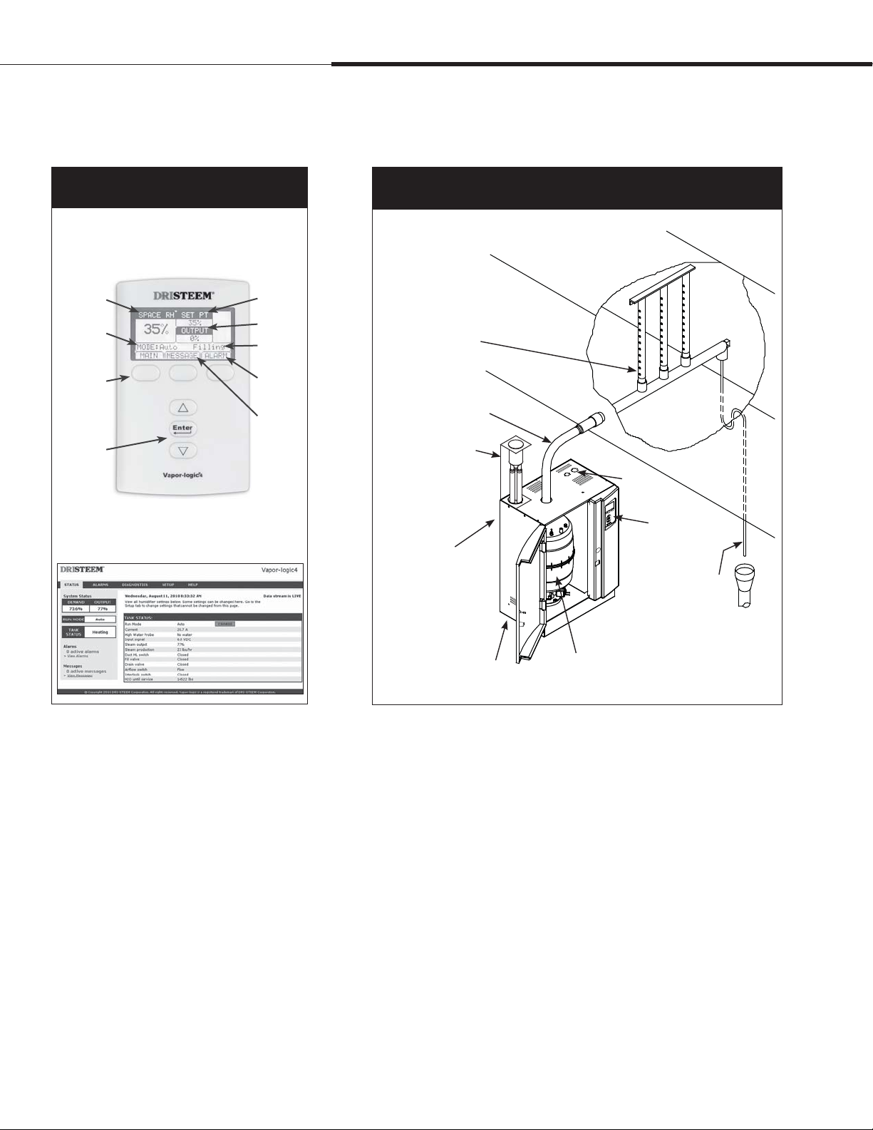
Product overview
Figure 2-1:
Vapor-logic controller interfaces
Keypad/display
Room RH
Mode
Softkeys
for direct
menu
access
Navigation
buttons
for item
selection
Web interface
Set point
Output
Cylinder
status
System
alarms
System
messages
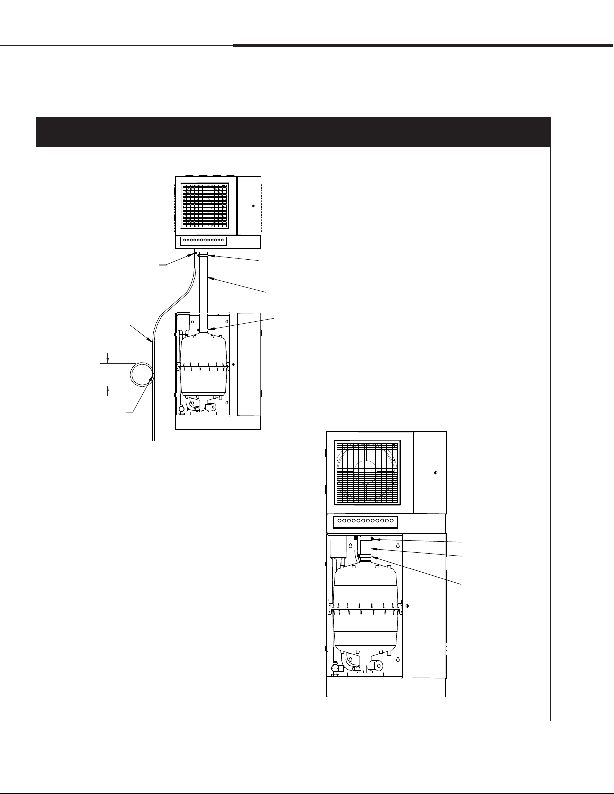
Figure 2-2:
XT humidifier installation overview
Duct
Rapid-sorb
dispersion panel
Steam hose, tubing,
or pipe to duct dispersion
or XT steam blower (XTSB)
Fill cup extension kit
required for some
models and applications
(see Page 11)
Wall mounting
keyholes
(behind cabinet)
Electrical
knockouts
Vapor-logic4
keypad/display
Condensate to drain
Notes:
See Pages 14 and 15 for detailed installation
drawings.
Damage caused by chloride corrosion is not
covered by your DRI-STEEM warranty.
Water fill line connection
(under cabinet)
Replaceable steam cylinder
OM-7586
Supply water
XT electrode steam humidifiers use hard or softened supply water.
Water conductivity must be in the range of 125 to 1250 μS/cm
(roughly equivalent to 3.4 to 36.3 grains per gallon). See “Supply
water considerations” on Page 44.
Demineralized, deionized, and reverse-osmosis water cannot be
used, because they are not conductive enough for electrode steam
humidifiers.
Heated supply water cannot be used, because unheated supply water
is required for drain water tempering.
Page 2 • DRI-STEEM XT Electrode Steam Humidifier Installation, Operation, and Maintenance Manual
Page 7
Product overview
Overview
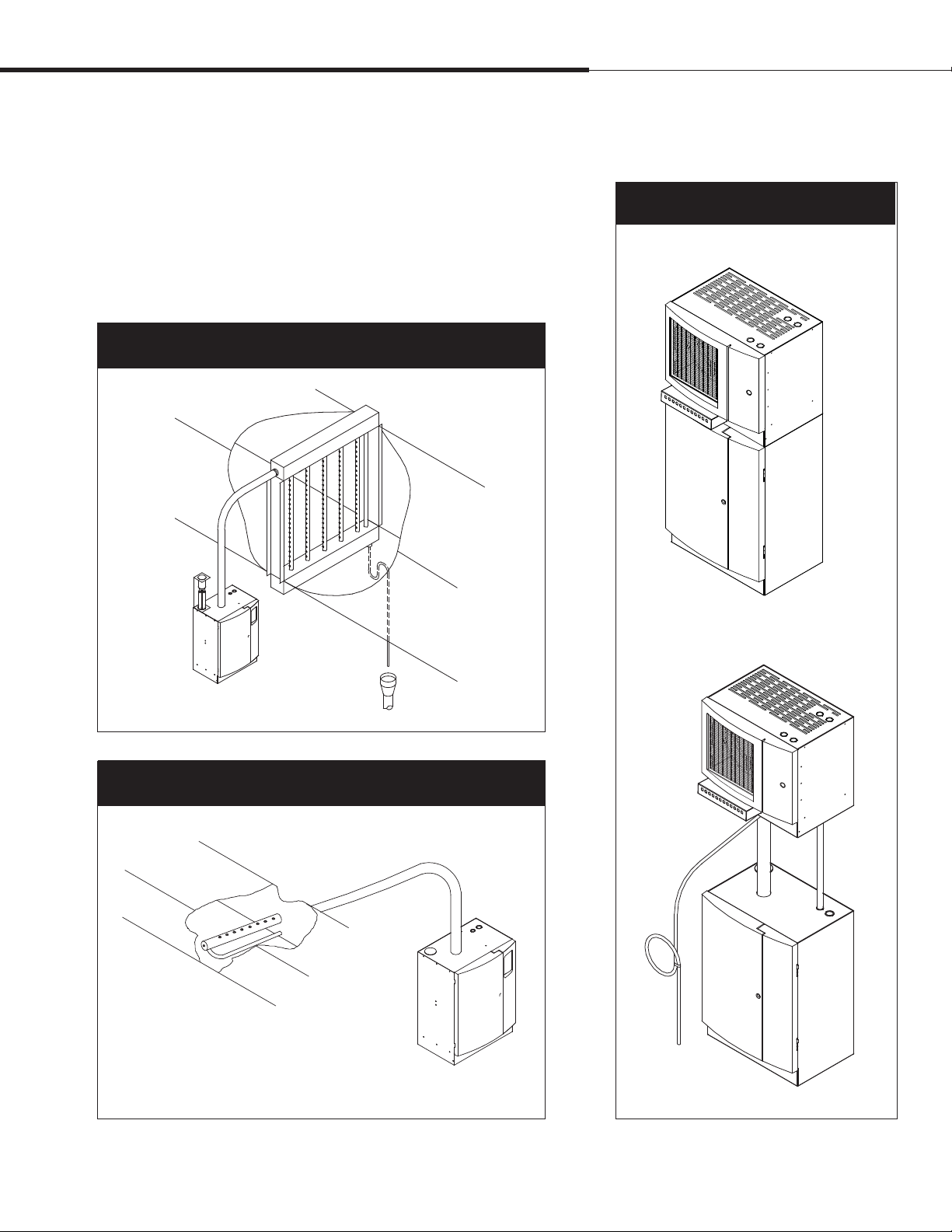
Dispersion options
In addition to Rapid-sorb dispersion shown in Figure 2-2, the duct
dispersion options below and the open space dispersion options
in Figure 3-3 are available for XT humidifiers. See “Dispersion”
beginning on Page 23.
Figure 3-1:
Ultra-sorb Model LV or LH dispersion
Model LV shown
Figure 3-3:
XT steam blowers (XTSB)
Mounted on top of humidifier
OM-7596
Mounted up to 10' (3 m) away from humidifier
Figure 3-2:
Single dispersion tube
Note: Models XT-30 and larger require condensate drain when using 1½“
(DN40) pipe or hose.
OM-7587X
OM-7585
OM-7597
DRI-STEEM XT Electrode Steam Humidifier Installation, Operation, and Maintenance Manual • Page 3
Page 8
Overview
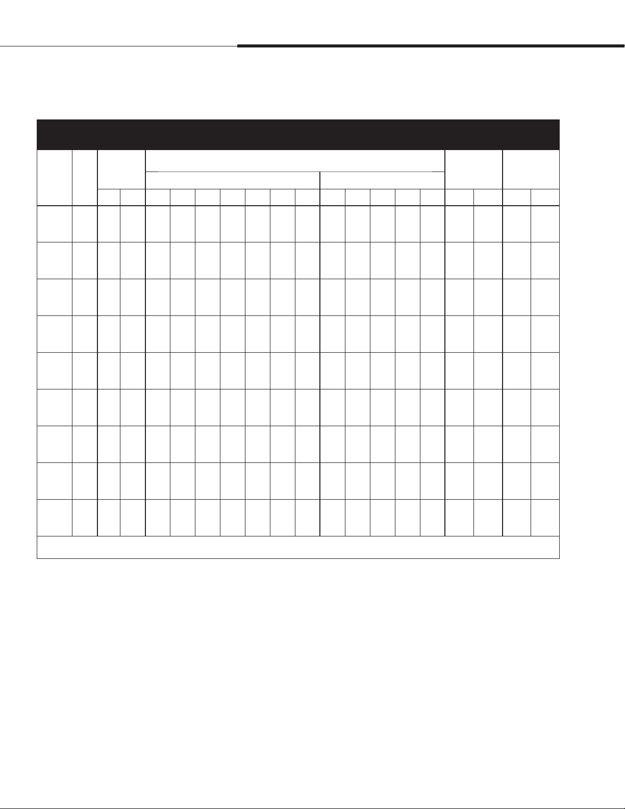
Table 4-1:
XT humidifier specifications
Specifications, capacities and
weights
Current draw (amps)
Max. steam
XT
model kW
5 1.7 5 2.3 14.2 8.2 7.4 7.1 — — — — — — — — 47.2 21.4 46.3 21.0
10 3.4 10 4.5 — 16.3 14.8 14.2 12.3 7.1 5.7 9.4 8.2 4.9 4.1 3.3 47.2 21.4 46.3 21.0
20 6.7 20 9.1 — 32.2 29.1 27.9 24.2 14.0 11.2 18.6 16.1 9.7 8.1 6.4 48.1 21.8 54.0 24.5
30 10.1 30 13.6 — ——————28.0 24.3 14.6 12.1 9.7 62.2 28.2 87.5 39.7
50 16.8 50 22.7 — ——————46.6 40.4 24.2 20.2 16.2 62.2 28.2 87.5 39.7
75 25.1 75 34.0 — ————————36.2 30.2 24.2 75.2 34.1 124.3 56.4
100 33.5 100 45.4 — ————————48.4 40.3 32.2 75.2 34.1 124.3 56.4
capacity
lbs/hr kg/h 120V 208V 230V 240V 277V 480V 600V 208V 240V 400V 480V 600V lbs kg lbs kg
Single-phase Three-phase
Shipping
weight
Max.
operating
weight
150 50.3 150 68.1 — ————————72.6 60.5 48.4 129.2 58.6 242.9 110.2
200 67.0 200 90.8 — ————————96.7 80.6 64.5 129.2 58.6 242.9 110.2
Note: For circuit protection requirements, see Table 5-1.
mc_090110_1020
Page 4 • DRI-STEEM XT Electrode Steam Humidifier Installation, Operation, and Maintenance Manual
Page 9
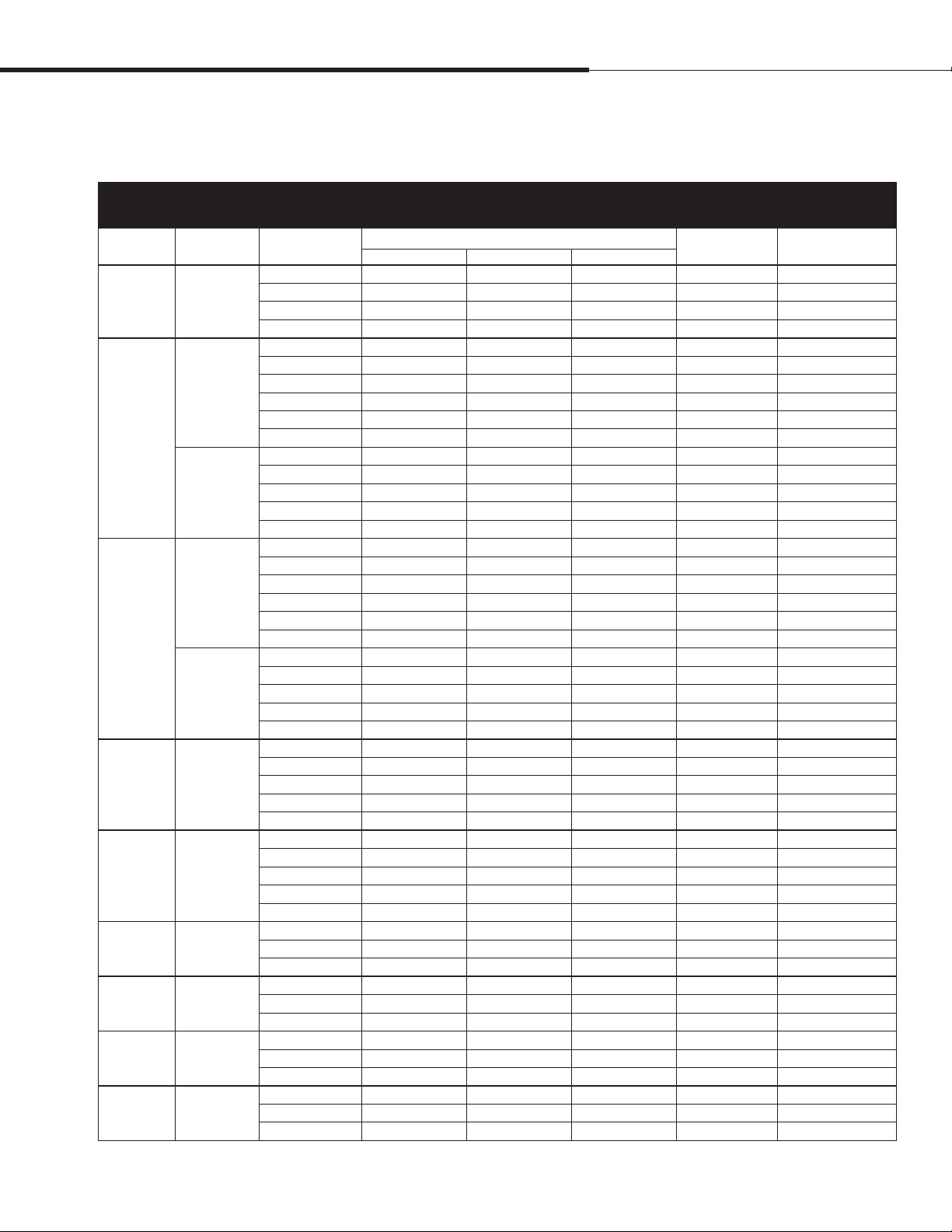
Fusing and line currents
Table 5-1:
Recommended fusing and line currents for XT humidifiers
Model Phase Volts
XT-5 1
1
XT-10
3
1
XT-20
3
XT-30 3
XT-50 3
XT-75 3
XT-100 3
XT-150 3
XT-200 3
mc_110110_1457
120 14.2 14.2 — 1.7 25
208 8.2 8.2 — 1.7 15
230 7.4 7.4 — 1.7 13
240 7.1 7.1 — 1.7 15
208 16.3 16.3 — 3.4 25
230 14.8 14.8 — 3.4 25
240 14.2 14.2 — 3.4 25
277 12.3 12.3 — 3.4 20
480 7.1 7.1 — 3.4 15
600 5.7 5.7 — 3.4 10
208 9.4 9.4 9.4 3.4 15
240 8.2 8.2 8.2 3.4 15
400 4.9 4.9 4.9 3.4 13
480 4.1 4.1 4.1 3.4 10
600 3.3 3.3 3.3 3.4 10
208 32.2 32.2 — 6.7 50
230 29.1 29.1 — 6.7 50
240 27.9 27.9 — 6.7 45
277 24.2 24.2 — 6.7 40
480 14.0 14.0 — 6.7 25
600 11.2 11.2 — 6.7 20
208 18.6 18.6 18.6 6.7 30
240 16.1 16.1 16.1 6.7 25
400 9.7 9.7 9.7 6.7 16
480 8.1 8.1 8.1 6.7 15
600 6.4 6.4 6.4 6.7 10
208 28.0 28.0 28.0 10.1 45
240 24.3 24.3 24.3 10.1 40
400 14.6 14.6 14.6 10.1 25
480 12.1 12.1 12.1 10.1 20
600 9.7 9.7 9.7 10.1 15
208 46.6 46.6 46.6 16.8 70
240 40.4 40.4 40.4 16.8 70
400 24.2 24.2 24.2 16.8 40
480 20.2 20.2 20.2 16.8 35
600 16.2 16.2 16.2 16.8 25
400 36.2 36.2 36.2 25.1 63
480 30.2 30.2 30.2 25.1 50
600 24.2 24.2 24.2 25.1 40
400 48.4 48.4 48.4 33.5 80
480 40.3 40.3 40.3 33.5 70
600 32.2 32.2 32.2 33.5 50
400 72.6 72.6 72.6 50.3 125
480 60.5 60.5 60.5 50.3 100
600 48.4 48.4 48.4 50.3 80
400 96.7 96.7 96.7 67.0 150
480 80.6 80.6 80.6 67.0 125
600 64.5 64.5 64.5 67.0 100
L1 L2 L3
Line amps
kW
Overview
Recommended
fusing amps
DRI-STEEM XT Electrode Steam Humidifier Installation, Operation, and Maintenance Manual • Page 5
Page 10
Overview
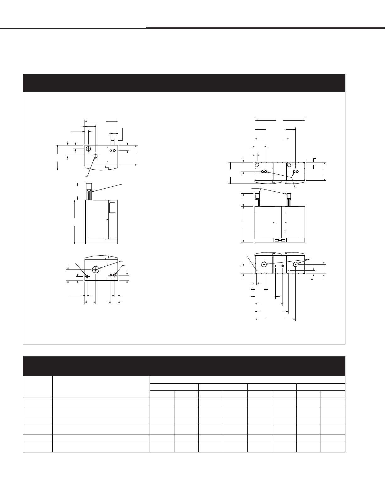
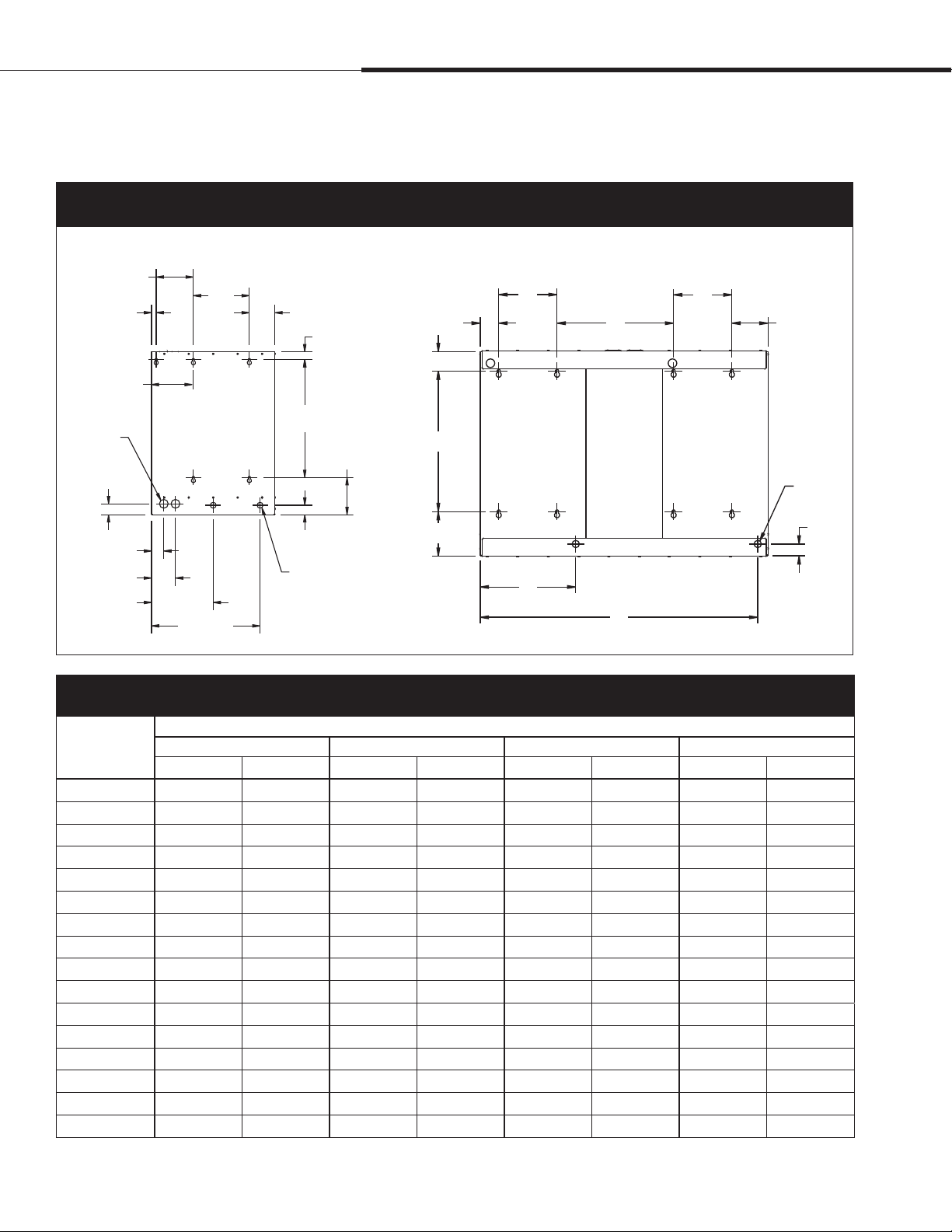
Dimensions
Figure 6-1:
XT humidifier dimensional drawings
Labeled dimensions: inches (millimeters). See mounting dimensions and electrical knockouts in Figure 8-1.
Top
Front
Bottom
2.00 (51)
C
Dispersion outlet
Water fill line
connection
1.38 (34.9)
XT models 5 through 100
E
2.00
(51)
F
10
(254)
B
F
2.38
(60.3)
(102.9)
E
XT models 150 and 200
Top
Fill cup extension kits*
Front
Bottom
E
1.85 (47)
F
C
10 (254)
B
Water fill line
connection
6.1 (155)
1.38 (35)
E
17.4 (442)
4.1
2.05
(52.1)
3.05
(77.5)
D
Fill cup extension kit*
Drain outlet
Electrical knockouts
3.05 (77.5)
2.05 (52.1)
4.05 (102.9)
OM-7581
A
32.2 (818)
26.8 (681)
22.09
(561)
26.38 (670)
32.2 (818)
A
1.85 (47)
D
Dispersion outlets
Drain outlets
F
2.36
(60)
OM-7593
* Fill cup extension kit is required for XT humidifier models 75 through 200 (ships loose with these models), for all XT humidifiers using Rapid-sorb or Ultra-sorb
dispersion, and for all XT humidifiers with more than 20' (6 m) maximum developed length of tubing/pipe from humidifier to dispersion assembly.
mc_090710_0946
Table 6-1:
Dimensions by model number
XT models
Dimension Description
A Cabinet width 16.06 408 19.21 488 21.46 545 39.76 1010
B Cabinet height 23.94 608 25.83 656 27.99 711 27.99 711
C Cabinet depth including doors 12.05 306 14.09 358 16.89 429 16.97 431
D Cabinet depth not including doors 10.00 254 11.80 300 14.40 184 14.40 184
E Cabinet left edge to steam/drain outlet centers 4.61 117 6.22 158 7.20 183 7.24 184
F Cabinet back edge to steam/drain outlet centers 6.14 156 6.18 157 7.24 184 7.24 184
mc_091010_0920
Page 6 • DRI-STEEM XT Electrode Steam Humidifier Installation, Operation, and Maintenance Manual
5, 10, and 20 30 and 50 75 and 100 150 and 200
inches mm inches mm inches mm inches mm
Page 11

Selecting a location
Installation
Humidifier
When selecting a location for the humidifier, consider the
following:
• Proximity to the duct
Install the humidifier near the air duct system where
the dispersion assembly will be located. The maximum
recommended length for steam hose connecting a single
humidifier to a dispersion assembly is 10' (3 m). The maximum
recommended developed length for tubing or pipe connecting a
single humidifier to a dispersion assembly is 20' (6 m).
For more information about installing dispersion assemblies,
see “Dispersion” beginning on Page 23.
• Elevation of the installed dispersion assembly
The recommended installation location for the dispersion
assembly is at an elevation higher than the humidifier. However,
if the dispersion assembly must be installed at an elevation
lower than the humidifier, install a drip tee and drain. See “Drip
tee installation” on Page 28.
Before installing a dispersion assembly or interconnecting
piping, review all pitch requirements in the “Dispersion” section
of this manual.
Important:
Install humidifier only in locations that meet the
following temperature and relative humidity (RH)
requirements:
Maximum ambient temperature:
104 °F (40 °C)
Minimum ambient temperature:
41 °F (5 °C)
Maximum ambient humidity:
80% RH (non-condensing)
• Required clearances (see Figure 9-1)
• Electrical connections
Electrical power supply connections are at the lower or upper
right rear corner of the unit. See “Humidifier wiring” on Pages
19 and 20.
• Supply water and drain piping connections
Water supply piping and drain connections are at the bottom of
the cabinet. See “Piping” on Pages 14 and 15.
• Exterior wall insulation
Install the humidifier on an exterior wall only if the wall is
properly insulated.
Dispersion control devices
See Figure 22-1 for recommended installation locations for the
dispersion assembly and associated control devices.
mc_062810_0928-NA
DRI-STEEM XT Electrode Steam Humidifier Installation, Operation, and Maintenance Manual • Page 7
Page 12
Installation
Figure 8-1:
XT humidifier mounting keyhole locations
XT models 5 through 100 XT models 150 and 200
D
A
G
P
Ø N
H
C
B
Mounting:
Keyhole locations and dimensions
A
E
D
E
B
F
G
A
C
Ø N
F
J
K
mc_091010_0923
J
K
L
M
I
Ø O
OM-7582
Table 8-1:
XT humidifier mounting keyhole dimensions
XT models
Dimension
A 5.00 127 8.15 207 9.62 244 8.00 203
B 16.52 420 18.12 460 20.24 514 19.27 489
C 3.60 91 3.60 91 4.39 112 4.95 126
D — — — — 6.39 162 2.54 65
E 0.97 25 1.33 34 1.33 34 2.73 69
F 6.40 163 6.40 163 6.40 163 6.19 157
G — — — — 0.80 20 16.00 406
H 1.88 48 1.88 48 1.88 48 — —
I 1.63 41 1.63 41 1.63 41 1.70 43
J 2.06 52 2.06 52 2.11 54 13.10 333
K 4.06 103 4.06 103 4.11 104 38.09 967
L 7.89 200 9.47 241 10.59 269 — —
M 14.43 367 17.44 443 18.65 474 — —
N 1.51 38 1.51 38 1.51 38 1.00 25
O 1.00 25 1.00 25 1.00 25 — —
P 7.12 181 7.12 181 7.19 183 — —
mc_091010_0925
5, 10, and 20 30 and 50 75 and 100 150 and 200
inches mm inches mm inches mm inches mm
I
OM-7594
Page 8 • DRI-STEEM XT Electrode Steam Humidifier Installation, Operation, and Maintenance Manual
Page 13
Mounting:
Clearances
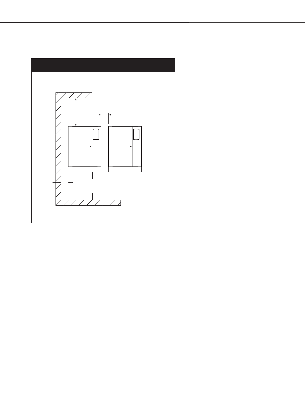
Figure 9-1:
XT humidifier recommended minimum clearances
Installation
3”
(76 mm)
mc_091010_0922
16” (400 mm)
15” (380 mm)
3” (76 mm) between units
36” (914 mm)
front clearance
OM-7583
DRI-STEEM XT Electrode Steam Humidifier Installation, Operation, and Maintenance Manual • Page 9
Page 14
Installation
Mounting
Opening and closing cabinet doors
To open the cabinet doors, use a slotted
screwdriver to rotate the quarter-turn
fastener counterclockwise so the slot is
vertical.
To close the doors, close the right then
the left door, and push the quarter-turn
fastener while turning clockwise so the slot
is horizontal.
WARNING
Mounting hazard
Mount humidifier per the instructions
in this manual and to a structurally
stable surface. Improper mounting of
the humidifier can cause it to fall or tip,
resulting in severe personal injury or
death.
mc_060110_1540
Unpack the humidifier from the shipping carton, and remove the
cabinet doors and steam cylinder.
Removing cabinet doors
XT humidifier and XTSB doors have lift-off hinges for easy removal
of open doors. The doors are captivated when closed but should be
removed when open. An upward bump could damage the door if it
jumps the hinges and falls.
Removing steam cylinder
Make sure the cylinder is empty and cooled before removing it.
1. Disconnect electrode and high water sensor connectors from
steam cylinder.
2. Place hands palms-down below cylinder on both sides of drain
outlet.
3. Press up against bottom of cylinder with backs of hands while
pressing down against cabinet floor with fingers.
4. Raise cylinder until drain outlet clears drain valve body, and
remove cylinder from cabinet.
Wall mounting humidifier
Follow the instructions below for your model and wall type, and
mount the humidifier level and plumb. See Figures 14-1 and 15-1.
• Wood studs 16" (406 mm) on center, XT models 75 through 200:
Mark hole locations at centers of studs, and predrill ¼" (6 mm)
diameter pilot holes. Secure humidifier to wall with lag bolts
(provided).
• Metal studs 16" (406 mm) on center, XT models 75 through 200:
Mark hole locations at centers of studs. Using a drill bit just large
enough to push a 3/8" (10 mm) bolt through, drill through studs
and wall, and through a backing plate on other side of wall. Push
bolts through wall, studs, and backing plate. Secure humidifier to
wall with bolts, and secure backing plate with washers and nuts.
• XT models 5 through 50, and XT models 75 through 200 if
16"-on-center (406 mm) studs are not available:
Mount spanner boards on wall, spanning at least two studs.
Position one board at top of cabinet (for the lag bolts), and the
other board at bottom of cabinet. Secure humidifier to spanner
boards with lag bolts.
• Hollow block or poured concrete wall, any XT model:
Mark hole locations, and drill appropriate pilot holes for two 3/8"
(10 mm) toggle bolts or two 3/8" (10 mm) machine bolt lead
anchors. Secure humidifier in place with bolts and anchors.
Page 10 • DRI-STEEM XT Electrode Steam Humidifier Installation, Operation, and Maintenance Manual
Page 15
Fill cup extension kit
Installation
A fill cup extension kit (Figure 11-1) is required for any of the
following:
• XT humidifier models 75 through 200 (fill cup extension kit
ships loose with these models)
• All XT humidifiers using Ultra-sorb or Rapid-sorb dispersion
• All XT humidifiers with more than 20' (6 m) maximum
developed length of tubing/pipe from humidifier to dispersion
assembly
mc_110110_1455
Removing existing fill cup: XT models 5 through 50
If installing a fill cup extension kit for XT models 5 through 50, first
remove the existing fill cup as follows:
1. Remove steam cylinder from XT cabinet (if not already out).
See “Removing steam cylinder” on Page 10.
2. Expand spring clamps and slide them up cylinder fill hose and
supply water hose, and disconnect hoses from fill connection
and fill valve adapter.
3. Disconnect overflow hose from overflow elbow.
4. Fill cup is press fit into top of XT cabinet. Rock fill cup back
and forth while pushing up until it comes out, then remove fill
cup and hoses.
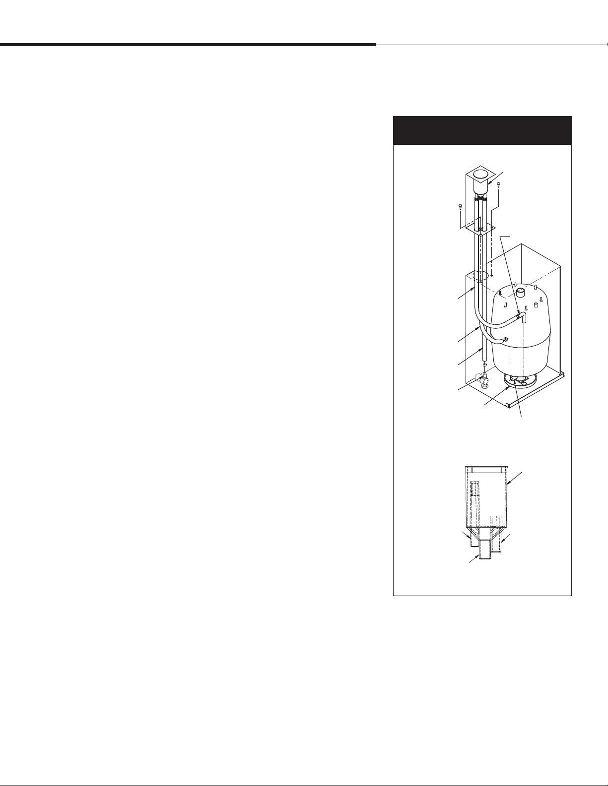
Installing fill cup extension kit: all XT models
1. Remove steam cylinder(s) from XT cabinet (if not already out).
See “Removing steam cylinder” on Page 10.
2. Route fill cup extension kit hoses into cabinet through fill cup
hole, and fasten extension bracket as shown with two screws
provided.
3. Cut supply water hose (small-diameter hose) (A) to length so it
can attach to fill valve adapter without kinking.
4. Expand spring clamp and slide it onto supply water hose (A)
far enough so it will not interfere, then push hose onto fill valve
adapter. Expand and slide spring clamp into place.
5. Cut cylinder fill hose (bottom, center hose) (B) to length so it
can attach to fill connection without kinking.
6. Expand spring clamp and slide it onto cylinder fill hose (B)
far enough so it will not interfere, then push hose onto fill
connection. Expand and slide spring clamp into place.
7. Cut overflow hose (C) to length so it can attach to overflow
elbow without kinking.
8. Push overflow hose onto overflow elbow. No spring clamp is
required on this connection.
Figure 11-1:
Fill cup extension kit
Overflow hose (C)
Cylinder fill hose (B)
Supply water hose (A)
Fill valve adapter
Drain cup plate
Supply water (A)
Cylinder fill (B)
mc_102810_1430
Fill cup
(see inset below)
Overflow elbow
OM-7588
Fill connection
Fill cup
Overflow (C)
OM-7629
DRI-STEEM XT Electrode Steam Humidifier Installation, Operation, and Maintenance Manual • Page 11
Page 16
Installation
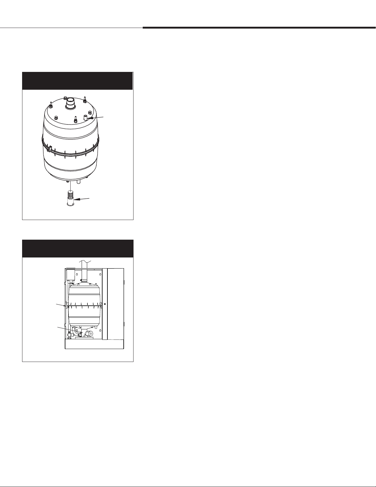
Steam cylinder
Figure 12-1:
Steam cylinder installation
Strainer
Figure 12-2:
Steam cylinder installation
High water
sensor pin
OM-7623X
Installing steam cylinder
1. Make sure strainer is pressed into steam cylinder drain outlet
and strainer flange is flush with bottom of cylinder outlet. See
Figure 12-1.
2. Use water to lubricate drain outlet on bottom of cylinder and
o-ring in drain valve body. See Figure 12-2.
3. With Warning label on cylinder facing you, lower cylinder drain
outlet into drain valve body, and rotate cylinder so side tabs line
up with cylinder guides inside cabinet. Push down on cylinder
until drain outlet is fully seated in drain valve body.
4. Connect high water sensor (yellow) wire to single pin
surrounded by plastic shoulder on cylinder.
5. Connect electrode plugs to pins on cylinder. Make sure all plugs
fit snugly and are fully engaged on pins.
Note: If cylinder plugs becomes loose, obtain replacement plugs
from DRI-STEEM. See “Replacement parts" on Pages 55
and 57 for part numbers.
Important: Cylinders with six electrodes have color-coded
dots on the cylinder and color bands on the electrode plugs.
When connecting the plugs, match the band colors on the plugs
with the dot colors on the cylinder. Refer to the wiring diagram
shipped with the humidifier if necessary.
Cylinder guide
Drain valve body
OM-7623X
Condensate return guidelines
To prevent overfilling the steam cylinder, follow the guidelines
below when returning condensate to the cylinder:
• When condensate can be returned to the steam cylinder:
– Single tube dispersion
– Less than 20 lbs/hr (9.1 kg/h) of steam production
– 20' (6 m) or less of steam hose, tubing, or pipe between
humidifier and dispersion
• When condensate should be wasted to the drain:
– Ultra-sorb or Rapid-sorb dispersion
– Single tube dispersion with condensate drain and:
- 20 lbs/hr (9.1 kg/h) or of more steam production, or
- More than 20' (6 m) of steam hose, tubing, or pipe between
humidifier and dispersion
Page 12 • DRI-STEEM XT Electrode Steam Humidifier Installation, Operation, and Maintenance Manual
Page 17
Piping:
Supply water and drain
Installation
Supply water piping
Use only copper for supply water piping; do not use rubber or
plastic. The standard supply water connection before the fill valve is
a 1/4" FIP strainer.
Note: The supply water connection size is 3/8"BSP [DN10] in Europe.
In cases where water hammer may be a possibility, consider
installing a shock arrestor. Water pressure must be 25 to 80 psi
(175 to 550 kPa).
Drain piping
Drain piping must be code-approved, ¾" (DN 20) ID material rated
for 212 °F (100°C) minimum.
The XT drain cup has an integral grounding plate and requires
a field-installed 1" (25 mm) air gap to a drain funnel to prevent
conduction of electricity in the drain line.
The XT humidifier tempers drain water by opening the fill valve
whenever the drain valve is energized, which automatically cools
drain water before it enters the drain. Drain water tempering is
intended to keep water entering the drain line no hotter than 140°F
(60°C). However, manually energizing the drain valve when the
supply water is shut off can allow 212 °F (100 °C) water to enter the
drain line.
Observe following precautions when selecting and installing drain
piping to ensure personal safety and material integrity:
• When using copper or other metallic drain piping, ground the
drain piping to the earth ground lug in the XT humidifier.
• Chlorinated polyvinyl chloride (CPVC) piping is a non-metallic
alternative for drain piping. It is rated up to 212°F (100°C) for
intermittent-use, low-pressure applications.
The connection size for the steam cylinder drain is 1" (DN25) hose.
Do not reduce this connection size.
If drainage by gravity is not possible, use a reservoir pump rated for
212 °F (100 °C) water.
A drain hose is provided to function as the flexible connection from
the drain cup to the field-installed open drain. See Figure 13-1.
Piping drawings:
See the piping drawings on Pages 14 and 15.
Important: Thoroughly flush the
supply water piping to remove pipe residue
and stagnant water before connecting piping
to the humidifier. Pipe residue and stagnant
water in the water supply piping can cause
foaming, preventing the humidifier from
reaching the required steam capacity.
WARNING
Hot drain pipes
Drain piping surface may be hot. Touching
or contact with hot pipe may cause severe
personal injury.
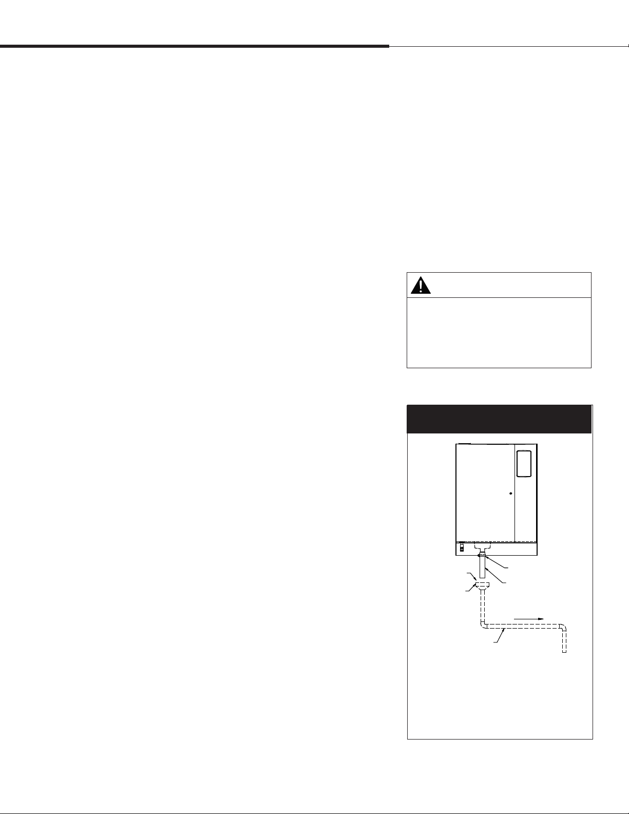
Figure 13-1:
Drain piping detail
1" (25 mm) air gap
Open drain
Hose clamp*
Black rubber hose*
Pitch 1/8”/ft (1%) towards drain
¾" (DN20) I.D.
To drain
* Hose clamp and black rubber hose ship with each humidifier;
they can also be ordered from DRI-STEEM. See the
replacement parts section of this manual for part numbers.
mc_102810_1415
DRI-STEEM XT Electrode Steam Humidifier Installation, Operation, and Maintenance Manual • Page 13
OM-7589
Page 18
Installation
Piping:
XT models 5 through 100
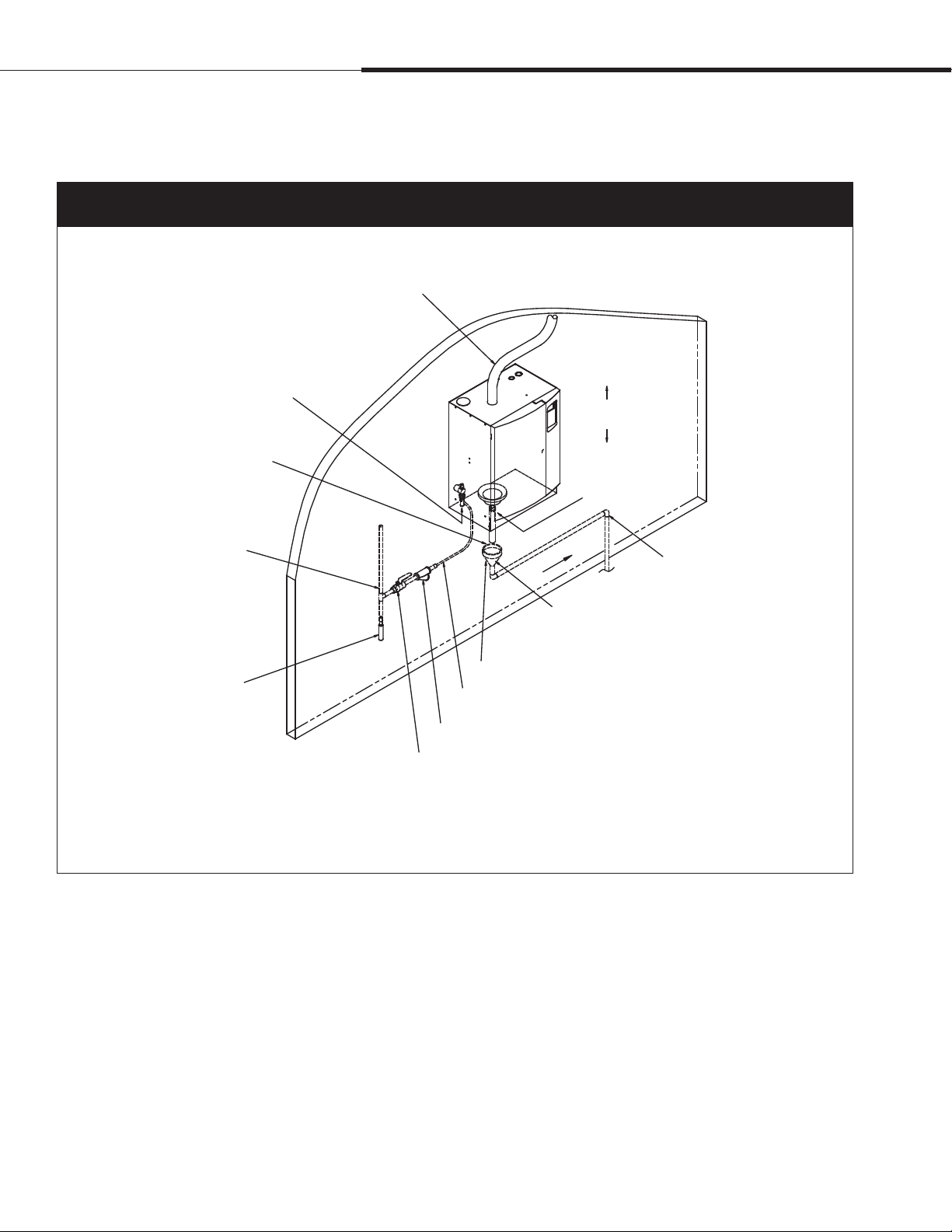
Figure 14-1:
XT humidifier field piping overview, models 5 through 100
Steam hose; may also use tubing or pipe.
See Table 24-1 for maximum piping lengths.
Tubing or pipe must be grounded.
Fill valve with 1/4” FIP strainer
(3/8"BSP [DN10] in Europe)
1” (25 mm) air gap required to isolate drain
water from cylinder water. Locate air gap
only in spaces with adequate temperature
and air movement to absorb flash steam, or
condensing on nearby surfaces could occur.
Install plumb
Hose and clamp
* Pitch 1/8”/ft (1%)
toward drain
Metallic water supply line
Shock arrester (by installer)
recommended to reduce water hammer
Dashed lines indicate provided by installer.
mc_090210_0845
Pitch*
Floor drain
Open drain required directly below humidifier drain to prevent
downstream drain line blockage from causing water to back up
into cylinder. Refer to governing codes for drain pipe size and
maximum discharge water temperature.
Plumb spill funnel to floor drain.
3/8” (DN10) copper water supply line; water pressure must be 25 to 80 psi
(175 to 550 kPa).
Inlet strainer, by installer
Supply valve, by installer
3/4” (DN20) drain piping. If piping run
is over 10’ (3 m), increase pipe to 1¼”
(DN32).
OM-7584
Page 14 • DRI-STEEM XT Electrode Steam Humidifier Installation, Operation, and Maintenance Manual
Page 19
Piping:
XT models 150 and 200
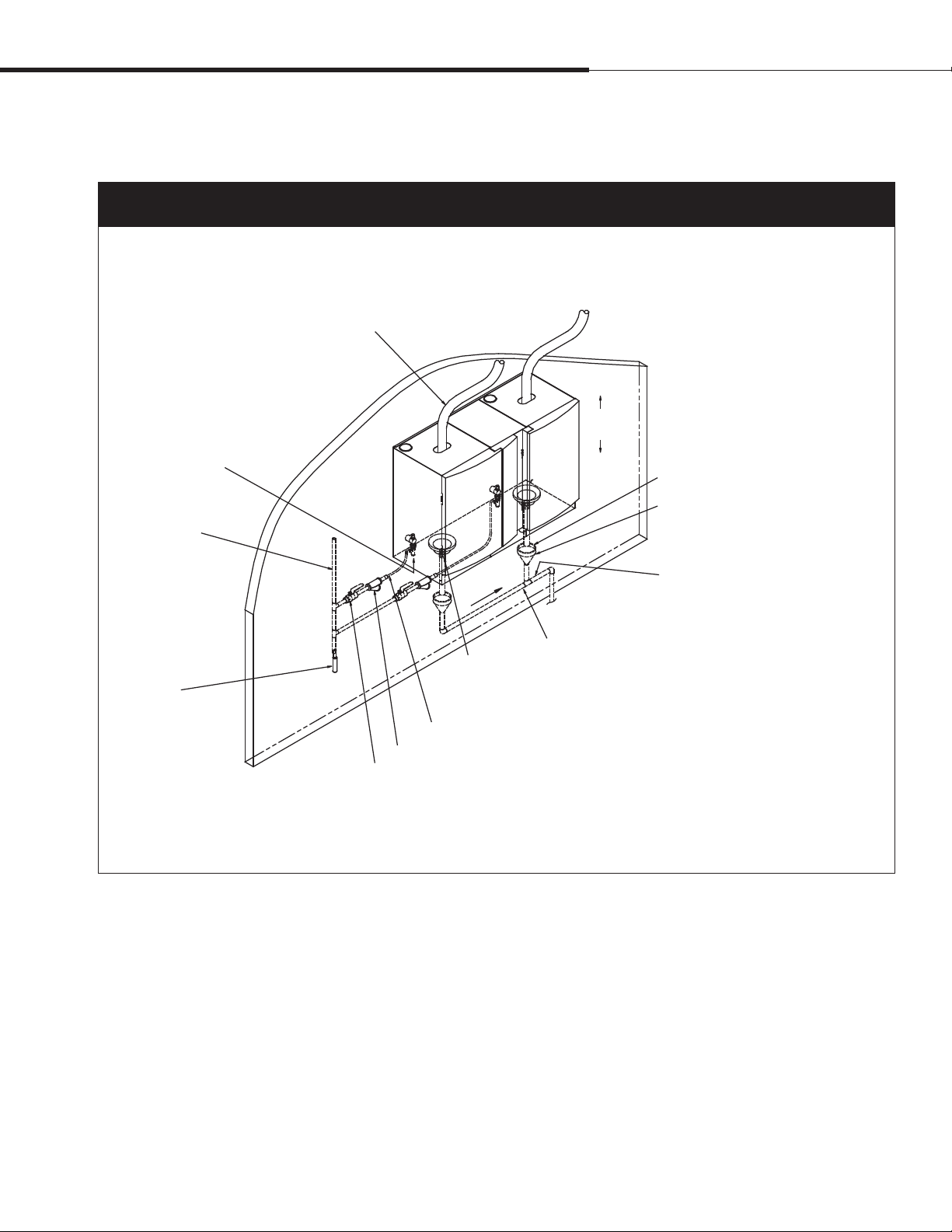
Figure 15-1:
XT humidifier field piping overview, models 150 and 200
Steam hose; may also use tubing or pipe.
See Table 24-1 for maximum piping lengths.
Tubing or pipe must be grounded.
Installation
Fill valve with 1/4”
FIP strainer
(3/8"BSP [DN10]
in Europe)
Metallic water
supply line
Shock arrester
(by installer)
recommended
to reduce water
hammer
Dashed lines indicate provided by installer.
mc_090210_0847
3/8” (DN10) copper water supply line; water pressure must be 25 to 80 psi (175 to 550 kPa).
Inlet strainer, by installer
Supply valve, by installer
Pitch*
Hose and clamp
Install
plumb
Floor drain
3/4” (DN20) drain piping up to second drain connection
* Pitch 1/8”/ft (1%) toward drain
1” (25 mm) air gap required to isolate drain water
from cylinder water. Locate air gap only in spaces
with adequate temperature and air movement
to absorb flash steam, or condensing on nearby
surfaces could occur.
Open drains required directly below humidifier
drains to prevent downstream drain line blockage
from causing water to back up into cylinder. Refer
to governing codes for drain pipe size and maximum
discharge water temperature.
1¼” (DN32) drain piping after second drain
connection
OM-7595
DRI-STEEM XT Electrode Steam Humidifier Installation, Operation, and Maintenance Manual • Page 15
Page 20
Installation
Piping:
XT steam blowers
o
Figure 16-1:
Piping from XT humidifier steam cylinders to XT steam blowers (XTSB)
XTSB mounted remotely
Maximum recommended distance between
humidifier and XTSB is 10’ (3 m).
Condensate hose
(purchased separately
from DRI-STEEM)
7” (178 mm)
water seal
Plastic tie
Plastic tie
To open drain or humidifier fill cup
Water seal is required, whether condensate is piped to open
drain or returned to humidifier fill cup.
Hose clamp (provided)
Steam hose (purchased separately from DRI-STEEM)
OM-7602
Hose clamp (provided)
XTSB mounted directly on top of
XT humidifier
Hose clamp (provided)
Steam hose (provided)
Hose clamp (provided)
OM-7603
mc_091010_0939
Page 16 • DRI-STEEM XT Electrode Steam Humidifier Installation, Operation, and Maintenance Manual
Page 21

Piping:
XT steam blowers
Figure 17-1:
Piping from XT humidifier steam cylinders to XTSBs with Y connectors
* Water seal is required, whether condensate is piped
to open drain or returned to humidifier fill cup.
Plastic tie
Pitch 2”/ft (15%) minimum
1½” (DN40) steam hose (provided)
Y connector (provided)
Installation
XTSB-50
Hose clamp (provided)
Plastic tie
1½” DN40 steam hose
(provided)
Y connector (provided)
Hose clamp
Hose clamp
7” (178 mm)
water seal
To open drain or
humidifier fill cup*
XT-75
Hose clamp (provided)
To open drain or
humidifier fill cup*
Pitch 2”/ft (15%)
minimum
Condensate hose (provided)
Plastic tie
OM-7604
Maximum recommended distance between
humidifier and XTSB is 10” (3 m).
XTSB-50
Hose clamp
(provided)
Hose clamp (provided)
mc_091010_0940
Condensate hose
(provided)
7” (178 mm)
water seal
Plastic tie
To open drain or
humidifier fill cup*
XT-150
To open drain or
humidifier fill cup*
DRI-STEEM XT Electrode Steam Humidifier Installation, Operation, and Maintenance Manual • Page 17
OM-7605
Page 22

Installation
Piping:
XT steam blowers
Figure 18-1:
Piping from XT humidifier steam cylinders with multiple outlets to XTSBs
* Water seal is required, whether condensate is piped
to open drain or returned to humidifier fill cup.
XTSB-50
1½” (DN40) steam hose (provided)
7” (178 mm)
water seal
Plastic tie
Plastic tie
To open drain or
humidifier fill cup*
Pitch 2”/ft (15%) minimum
XT-100
To open drain or
humidifier fill cup*
Hose clamp (provided)
Hose clamp (provided)
Condensate hose (provided)
Plastic tie
Maximum recommended distance between
humidifier and XTSB is 3 m.
Pitch 2”/ft (15%)
minimum
OM-7606
XTSB-50
Hose clamp (provided)
1½” (DN40) steam
hose (provided)
7” (178 mm)
water seal
mc_091410_1055
To open drain or
humidifier fill cup*
XT-200
To open drain or
humidifier fill cup*
Hose clamp (provided)
Condensate hose
(provided)
Plastic tie
Page 18 • DRI-STEEM XT Electrode Steam Humidifier Installation, Operation, and Maintenance Manual
OM-7607
Page 23

Humidifier wiring
Installation
All wiring must be in accordance with all governing codes and with
the unit wiring diagram. Power supply wiring must be rated for
105 °C. See Figure 19-1 for the humidifier wiring diagram locations
When selecting a location for installing the humidifier:
• Avoid areas close to sources of electromagnetic emissions such
as power distribution transformers.
• Do not loop power wiring.
• Do not use aluminum wire.
Conduit knockouts
Conduit and control wiring knockouts are provided on the
XT humidifier cabinet. See Figure 8-1.
CAUTION
Adding conduit connections not recommended
Adding alternate conduit connections is not recommended. If you
must make additional holes in the humidifier cabinet, protect all
internal components from debris, and vacuum out the cabinet when
finished. Failure to follow these precautions can damage sensitive
electronic components and void the DRI-STEEM warranty.
d
Figure 19-1:
Field wiring requirements
Wiring diagram
inside of electrical
control cabinet door
XT Humidifier
Notes:
• Control wiring and power wiring must be run in dedicated
or separate earthed metal conduit, cable trays, or trunking.
• Separate the line voltage wiring from low voltage control
circuit wiring when routing electrical wiring inside the
humidifier cabinet.
• Do not use chassis or safety grounds as current-carrying
commons. Never use a safety ground as a conductor or
neutral to return circuit current.
Power
supply
Fused
disconnect
OM-7363
DRI-STEEM XT Electrode Steam Humidifier Installation, Operation, and Maintenance Manual • Page 19
Page 24

Installation
WARNING
Electric shock hazard
Only qualified electrical personnel
should perform field wiring installation
procedures. Improper wiring or contact
with energized circuits may cause property
damage, severe personal injury, or death
as a result of electric shock and/or fire.
Humidifier wiring
Control component placement
Follow the guidelines on Page 22
transmitters, and airflow proving switches.
Connection instructions
Before connecting power, refer to the wiring diagram or the data
plate on the outside of the cabinet for wire sizing amperage.
For control signal wiring from a humidistat, transmitter, or signal
by others, see the wiring diagrams shipped inside the humidifier.
See “Step 1 – Field wiring” in the Vapor-logic4 Installation and
Operation Manual for detailed instructions on the following:
• Control input wiring:
See the “Control input” section.
for placing humidistats,
WARNING
Excessive moisture hazard
DRI-STEEM strongly recommends installing
a duct airflow proving switch and a duct
high limit humidistat. These devices
prevent a humidifier from making steam
when there is low airflow in the duct or
when the RH level in the duct is too high.
Failure to install these devices can result
in excessive moisture in the duct, which
can cause bacteria and mold growth or
dripping through the duct.
mc_060310_0725
• Duct airflow proving switch and duct high limit humidistat
wiring (recommended optional devices):
See the following sections:
“Airflow proving switch” and
“Duct high limit switch or transmitter”
• Remote signal wiring:
See the following sections:
“Programmable triac” and
“Programmable relay (dry contact)”
Page 20 • DRI-STEEM XT Electrode Steam Humidifier Installation, Operation, and Maintenance Manual
Page 25

Humidifier wiring
Installation
Earth grounding requirements
A safety earth grounding system that meets national, state, and
local electrical codes is required. The ground connection must be
made with solid metal-to-metal connections. Ground wire should
be the same size as power wiring.
Proper wiring prevents electrical noise.
Electrical noise can produce undesirable effects
on electronic control circuits, which affects
controllability. Electrical noise is generated
by electrical equipment such as inductive
loads, electric motors, solenoid coils, welding
machinery, or fluorescent light circuits. The
electrical noise or interference generated from
these sources (and the effect on controllers)
is difficult to define, but the most common
symptoms are erratic control or intermittent
operational problems.
Important:
• For maximum EMC effectiveness, wire all
humidity, high limit, and airflow controls
using multicolored shielded/screened plenumrated cable with a drain wire for the shield/
screen. Connect the drain wire to the shield/
screen ground terminal with wire less than
2" (50 mm) in length.
• Do not ground shield at the device end.
DRI-STEEM XT Electrode Steam Humidifier Installation, Operation, and Maintenance Manual • Page 21
Page 26

Installation
Other factors affecting humidity control
Humidity control involves more than the
controller’s ability to control the system. Other
factors that play an important role in overall
system control are:
• Size of humidification system relative to load
• Overall system dynamics associated with
moisture migration time lags
• Accuracy of humidistats and humidity
transmitters and their location
• Dry bulb temperature accuracy in space or duct
• Velocities and airflow patterns in ducts and
space environments
• Electrical noise or interference
Humidistat and transmitter placement
Humidistat and sensor locations are critical
Humidistat and sensor location have a significant impact on
humidifier performance. In most cases, do not interchanging duct
and room humidity devices. Room humidity devices are calibrated
with zero or little airflow; whereas duct humidity devices require air
passing across them.
Recommended sensor locations (see figure below):
A Ideal. Ensures the best uniform mix of dry and moist air with
stable temperature control.
B Acceptable, but room environment may affect controllability,
such as when sensor is too close to air grilles, registers, or heat
radiation from room lighting.
C Acceptable. Provides uniform mixture of dry and moist air.
If extended time lag exists between moisture generation and
sensing, extend sampling time.
D Acceptable (behind wall or partition) for sampling entire room
if sensor is near an air exhaust return outlet. Typical placement
for sampling a critical area.
E Not acceptable. These locations may not represent actual overall
conditions in the space.
F Not acceptable. Do not place sensors near windows, door
passageways, or areas of stagnant airflow.
G Best sensing location for a high-limit humidistat or humidity
transmitter and airflow proving switch.
Figure 22-1:
Recommended humidistat and transmitter locations
Outside air
Damper control
Relief air Return air
E
A
mc_060508_0750-XT
C
F
Air handling unit
Window
E
High limit humidistat or high limit transmitter (set at
8' to 12'
(2.4 m to 3.7 m)
minimum
G
Wall or
partition
D
B
WindowDoorway
F
F
90% RH maximum) for VAV applications
Airflow switch or differential pressure switch (sail
type recommended for VAV applications)
Vapor absorption has taken place
Point of vapor absorption
Humidifier dispersion assembly
Turning vanes
DC-1084
Page 22 • DRI-STEEM XT Electrode Steam Humidifier Installation, Operation, and Maintenance Manual
Page 27

Dispersion:
Selecting the dispersion assembly
location
Installation
DRI-STEEM humidifiers operate with several types of dispersion
assemblies for open spaces and for ducts and air handling units.
Dispersion assemblies in ducts and air handling units must be
positioned where the water vapor being discharged is carried off
with the airstream and is absorbed before it can cause condensation
or dripping.
• For each dispersion device, DRI-STEEM documents distances
required for non-wetting to occur. For more information about
absorption non-wetting distances, see the non-wetting tables in
this humidifier's product catalog, available for viewing, printing
or ordering at www.dristeem.com.
• In general, the dispersion assembly is best placed where the
air can absorb the moisture being added without causing
condensation at or after the unit. This normally will be after the
heating coil or where the air temperature is highest.
• Place the dispersion assembly such that absorption will occur
– before the intake of a high efficiency filter, because the filter
can remove the visible moisture and become waterlogged;
– before coming in contact with any metal surface;
– before fire or smoke detection devices;
– before a split in the duct; otherwise, the dispersion assembly
can direct more moisture into one duct than the other.
• When draining dispersion condensate to an open drain, provide
a 1" (25 mm) air gap between the condensate drain piping
and the drain. Locate the gap only in spaces with adequate
temperature and air movement to absorb flash steam; otherwise,
condensation may form on nearby surfaces.
mc_060210_0838
Figure 23-1:
Ultra-sorb with the High-efficiency Tube
option
High-efficiency Tube option
Dispersion assemblies with the High-efficiency
Tube option are designed to produce significantly
less dispersion-generated condensate and
airstream heat gain, which reduces wasted
energy by up to 85%. These improvements
are accomplished by reducing the thermal
conductivity of the tubes with 1/8" of
polyvinylidene fluoride (PVDF) insulating material
on the outside of the tubes. These assemblies
require careful unpacking, installation, and
handling. If your dispersion assembly has the
High-efficiency Tube option, be sure to read this
section carefully.
mc_060208_1320
DRI-STEEM XT Electrode Steam Humidifier Installation, Operation, and Maintenance Manual • Page 23
Page 28

Installation
Dispersion:
Interconnecting piping requirements
Important:
Failure to follow the recommendations in
this section can result in excessive back
pressure on the humidifier. This will result
in unacceptable humidification system
performance such as leaking gaskets, blown
water seals, erratic water level control, and
spitting condensate from the dispersion tube.
mc_060210_0843
Important:
Reducing the inside diameter of the
interconnecting piping will result in the
internal humidifier system pressure exceeding
the parameters for acceptable performance.
mc_060210_0847
The steam outlet on the humidifier is sized to the output of
the humidifier. DO NOT use steam hose or interconnecting
tubing/piping with an inside diameter smaller than the humidifier
steam outlet. See note at left.
• See maximum steam carrying capacities in Table 24-1.
• If the humidifier must be located higher then the dispersion
assembly, use the recommend installation shown in Figure 28-1.
Connecting to humidifier with steam hose
• Support steam hose to prevent sags, or low spots, and to
maintain a minimum pitch of 2"/ft (15%) away from the
humidifier.
• Use DRI-STEEM steam hose. Other manufacturers of steam
hose may use unacceptable release agents or material mixes
that can affect humidifier system performance adversely. Using
hose from alternative manufacturers increases the possibility of
tank foaming and accelerated aging. Foaming causes condensate
discharge at the dispersion assembly.
• Do not use steam hose in outdoor applications.
• Do not insulate steam hose. Insulation causes accelerated heat
aging, causing the steam hose to become hard and susceptible to
failure due to cracks.
• For single tube applications, see hose kit sizes in Table 25-2.
Table 24-1:
Maximum steam carrying capacity and length of interconnecting steam hose, tubing, and pipe*
DRI-STEEM black steam hose
Hose I.D. Maximum capacity Maximum length** Tube or pipe size*** Maximum capacity
inches DN lbs/hr kg/h ft m inches DN lbs/hr kg/h ft m
1½ 40 150 68 10 3 1½ 40 150 68 20 6
2 50 250 113 10 3 2 50 220 100 30 9
* Based on total maximum pressure drop in hose, tubing, or piping of 5" wc (1244 Pa).
** Maximum recommended length for steam hose is 10' (3 m). Longer distances can cause kinking or low spots.
*** To minimize loss of capacity and efficiency, insulate tubing and piping.
†
Developed length equals measured length plus 50% of measured length to account for pipe fittings. If maximum developed length is more than 20' (6 m), a fill
cup extension kit is required. See Figure 11-1.
††
Requires flange connection.
†††
When using steam hose, use DRI-STEEM steam hose for best results. Field-supplied hose may have shorter life and may cause foaming in the evaporating
chamber resulting in condensate discharge at the dispersion assembly. Do not use steam hose for outdoor applications.
mc_091410_1050-XT
†††
††
3
80
4†† 100
††
5
††
6
Copper or stainless steel tubing
and Schedule 40 steel pipe
125
150
††
††
††
††
450 204 80 24
750 340 100 30
1400 635 100 30
2300 1043 100 30
Maximum
developed length
†
Page 24 • DRI-STEEM XT Electrode Steam Humidifier Installation, Operation, and Maintenance Manual
Page 29

Dispersion:
Interconnecting piping requirements
Installation
Connecting to humidifier with tubing or pipe
• See Figures 30-1 and 31-1 for interconnecting tubing and pipe
pitch requirements for single tube applications. See Table 33-1
for interconnecting tubing and pipe pitch requirements for
Rapid-sorb applications.
• Support interconnecting piping between the humidifier steam
outlet and the dispersion system with pipe hangers. Failure
to properly support the entire steam piping weight may cause
damage to the humidifier tank and void the warranty.
• Steam supply adapters are available from DRI-STEEM. These
adapters convert a tubing outlet on the humidifier to threaded
pipe, allowing a pipe connection.
• 90° elbows are not recommended; use two 45° elbows, 1' (0.3 m)
apart.
• Thin wall tubing heats up faster and causes less start-up loss
than heavy wall pipe.
• Insulating hard pipe reduces the loss in output caused by
condensation.
• When using hard pipe, take care to remove ALL traces of
lubricants used to thread the pipe. This will minimize the
possibility of tank foaming. Denatured alcohol or mineral spirits
work best for removing lubricant.
mc_060310_1145-NA
Table 25-2:
Hose kit sizing by capacity
Maximum
tube capacity
lbs/hr kg/h
28.4 12.9 1½" (DN40) without drain
56.8 25.8 1½" (DN40) with drain
> 56.8 >25.8
Hose kit
(steam hose, dispersion tube,
and hardware)
These capacities require
multiple tube assemblies and
cannot use a single hose kit.
Grounding steam pipes
The XT humidifier has built-in functionality for detecting and
eliminating foaming in the steam cylinder. However, because brief
periods of foaming are possible, grounding metal steam pipes back
to the XT humidifier earth grounding lug is necessary. This earth
ground will prevent foam from creating an electrically conductive
path from the electrically charged cylinder water to the metal steam
pipe. The grounding lug is shown in Figures 54-1 and 56-1.
Table 25-1:
Steam loss of interconnecting steam hose, tubing and pipe
Description
Hose
Tubing
Pipe
Note: These data are based on an ambient air temperature of 80 °F (27 °C), fiberglass insulation, copper tubing, and Schedule 40 pipe.
mc_051310_1215-NA
Nominal hose, tubing or pipe size
inches DN lbs/hr/ft kg/h/m lbs/hr/ft kg/h/m inches mm
1½ 40 0.15 0.22 N/A N/A N/A N/A
2 50 0.20 0.30 N/A N/A N/A N/A
1½ 40 0.11 0.164 0.02 0.03 2 50
2 50 0.14 0.21 0.025 0.037 2 50
1½ 40 0.22 0.33 0.02 0.03 2 50
2 50 0.25 0.38 0.025 0.037 2 50
Noninsulated Insulated
Steam loss
Insulation thickness
DRI-STEEM XT Electrode Steam Humidifier Installation, Operation, and Maintenance Manual • Page 25
Page 30

Installation
Dispersion:
Interconnecting piping requirements
Figure 26-1:
Piping connections to Single dispersion tube, Rapid-sorb, and Ultra-sorb Model LV or LH dispersion assemblies
1½” (DN40) steam
hose
Connector kit
(provided)
Steam outlet connections to steam hose
(XT models 5, 10, 20 shown)
To dispersion assembly
Pitch steam hose 2”/ft (15%)
toward dispersion assembly.
Hose clamp
1” (DN25) steam hose
Steam outlet connections to tubing or pipe
(XT models 30, 50, 75 shown)
To dispersion assembly
Pitch steam hose 2”/ft (15%)
toward dispersion assembly.
1½” (DN40)
tubing or pipe
(must be grounded)
Hose clamp
1½” (DN40) I.D.
steam hose
Hose clamp
OM-7622
Steam hose and clamps are provided with these humidifiers.
mc_091010_1004
OM-7623
Page 26 • DRI-STEEM XT Electrode Steam Humidifier Installation, Operation, and Maintenance Manual
Page 31

Dispersion:
Interconnecting piping requirements
Figure 27-1:
Piping connections to Single dispersion tube, Rapid-sorb, and Ultra-sorb Model LV or LH dispersion assemblies
Installation
XT-100
Stainless steel
Y connector*
Hose
clamp*
* Stainless steel Y connector, two 1½” (DN40) hoses, and four hose
clamps ship with each XT-100 humidifier.
XT-200
Stainless steel tube
connector*
To dispersion assembly
Pitch steam hose 2”/ft (15%)
toward dispersion assembly.
2” (DN50)
steam hose
1½” (DN40)
steam hose*
OM-7619
XT-150
3” (DN80) flange connection
attached directly to dispersion
(see inset at right)
Stainless steel tube
connector*
Hose clamp*
1½” (DN40)
steam hose*
* Stainless steel tube connector, one 2" (DN50) hose, and two hose
clamps ship with each XT-150 humidifier.
2” (DN50) steam hose attached
directly to dispersion (see inset
below)
Hose clamp*
OM-7620
Connecting multiple cylinders to a dispersion assembly
2” (DN50) steam
hose
Stainless steel
Y connector*
1½” (DN40) steam
hose*
Hose
clamp*
OM-7621
* Stainless steel tube connector, two stainless steel Y-connectors, four 1½” (DN40) hoses,
and eight hose clamps ship with each XT-200 humidifier.
mc_091010_0938
steam hose connection
steam hoses from multiple cylinders
3” (DN80)
flange connection
2” (DN50) steam
hoses from multiple
cylinders
For multiple cylinders, connect the stainless steel tube connector (provided
with XT models 150 and 200; available for staged XT humidifiers) directly
to the dispersion inlet. The diameter and pitch of the tube connector
must match the inlet diameter and pitch of the dispersion unit. Connect a
maximum of two cylinders to the tube connector with steam hose, tubing,
or pipe.
2” (DN50)
1½” (DN40)
OM-7625
OM-7624
DRI-STEEM XT Electrode Steam Humidifier Installation, Operation, and Maintenance Manual • Page 27
Page 32

Installation
WARNING
Hot surface and steam hazard
Dispersion tube, steam hose, tubing, or
hard pipe can contain steam, and surfaces
can be hot. Discharged steam is not
visible. Contact with hot surfaces or air
into which steam has been discharged can
cause severe personal injury.
mc_060110_1555
Figure 28-1:
Drip tee installation
Dispersion:
Drip tee installation
Install a drip tee as shown below when the humidifier is mounted
higher than the dispersion assembly, when interconnecting hose or
piping needs to go over an obstruction, or when interconnecting
piping runs are long.
Important: Steam hose must be supported to prevent sagging
or low spots.
90° long sweep or two 45° elbows
Obstruction
Insulate tubing and hard pipe to reduce steam loss
To dispersion assembly
6" (150 mm) recommended
8" (200 mm) minimum
1" (25 mm) air gap
Pitch
Adapter
XT humidifier
Tubing or pipe drip tee, by installer. DRI-STEEM part
numbers for 304 stainless steel inline tees:
• 1½" (DN40) kit: 191071-001
• 2" (DN50) kit: 191071-002
¾" (DN20)
Open funnel or floor drain. See first note below.
Notes:
• Locate air gap only in spaces with adequate temperature and air movement to absorb flash steam; otherwise, condensation may form on nearby surfaces. Refer to governing codes for
drain pipe size and maximum discharge water temperature.
• Support steam hose so there are no sags or low spots.
• Dashed lines indicate provided by installer.
mc_062810_0645-XT
Page 28 • DRI-STEEM XT Electrode Steam Humidifier Installation, Operation, and Maintenance Manual
OM-7364X
Page 33

Dispersion:
Single dispersion tube
Installation
Installation notes
• Use DRI-STEEM’s hard pipe adapter kit to connect the steam
outlet to hard pipe. Use a hose clamp to connect the steam
outlet to steam hose. Use a hose cuff and clamps to connect the
steam outlet to tubing.
• Thin-walled tubing heats up faster than heavy-walled pipe
causing less steam loss at start-up.
• Hard pipe or tubing diameter must match XT steam outlet
connection.
• See the maximum steam carrying capacity and steam loss tables
on Pages 24 and 25.
• Maximum capacity of dispersion tube without condensate
drain:
– 1½" (DN40): 28.4 lbs/hr (13 kg/h)
– 2" (DN50): 56.8 lbs/hr (25.8 kg/h)
• Maximum capacity of dispersion tube with condensate drain:
– 1½" (DN40): 56.8 lbs/hr (25.8 kg/h)
– 2" (DN50): 85.2 lbs/hr (38.6 kg/h)
• Orient dispersion tube with tubelets (steam orifices) pointing
up.
• If mounting the humidifier above the level of dispersion tube,
see “Drip tee installation” on Page 28.
• Table 25-1 lists hose kit sizes by humidifier capacity. Note
that the capacities of Models XT-75 through XT-200 require
multiple tube assemblies and cannot use a hose kit. For multiple
tube assemblies, see “Rapid-sorb” beginning on Page 32.
mc_062810_1030-XT
See Single dispersion tube installation drawings
in Figures 30-1 and 31-1.
Important:
Failure to follow the recommendations in this
section can result in excessive back pressure on
the humidifier. This will result in unacceptable
humidification system performance such as
leaking gaskets, blown water seals, erratic water
level control, and spitting condensate from the
dispersion tube.
mc_060210_0843
DRI-STEEM XT Electrode Steam Humidifier Installation, Operation, and Maintenance Manual • Page 29
Page 34

Installation
Figure 30-1:
Single dispersion tube without condensate drain
Steam hose, tubing or pipe (tubing
or pipe must be grounded). Insulate
tubing and hard pipe to reduce
steam loss. Do not insulate steam
hose. See Table 24-1 for maximum
piping lengths.
See the first bullet in
Installation notes.
Adapter
Dispersion:
Single dispersion tube
Duct
Single dispersion tube without
condensate drain
Pitch*
Secure and seal
escutcheon plates
90° long sweep or
two 45° elbows
Mounting nut
3/8" - 16 (M10)
Tube pitch: 2"/ft (15%)
OM-7365X
* Pitch steam hose, tubing, or pipe
toward humidifier:
– 2"/ft (15%) when using steam
hose
– ½"/ft (5%) when using 1½"
tubing or pipe
Dashed lines indicate provided by installer.
mc_062810_0720-XT
XT humidifier
Dispersion tube escutcheon plate
A
Dimension A:
3.25" (82.5 mm) for 1½" tubes
A
OM-351-1
Page 30 • DRI-STEEM XT Electrode Steam Humidifier Installation, Operation, and Maintenance Manual
Page 35

Dispersion:
Single dispersion tube
Figure 31-1:
Single dispersion tube with condensate drain
Installation
Steam hose, tubing, or pipe (tubing or pipe must be
grounded). Insulate tubing and hard pipe to reduce
steam loss. Do not insulate steam hose. See Table
24-1 for maximum piping lengths.
90° long sweep
or two 45° elbows
See the first bullet in
Installation notes.
Adapter
* Pitch steam hose, tubing, or pipe toward dispersion tube:
– 2"/ft (15%) when using steam hose
– ½"/ft (5%) when using 1½" tubing or pipe
Dashed lines indicate provided by installer.
mc_062810_0725-XT
Secure and seal
escutcheon plates
Water seal
5" (125 mm)
1" (25 mm) air gap
XT humidifier
Pitch*
6" (150 mm)
recommended
Duct
¼" NPT (DN8)
¾" (DN20) (minimum) condensate drain tube by installer.
Must be suitable for 212 °F (100 °C) water.
Open drain required. Locate air gap only in spaces with adequate temperature and
air movement to absorb flash steam; otherwise, condensation may form on nearby
surfaces. Refer to governing codes for drain pipe size and maximum discharge water
temperature.
Dispersion tube
A
Dimension A:
3.25" (82.5 mm) for 1½" tubes
Single dispersion tube with condensate drain
Pitch tube toward
drain 1/8"/ft (1%)
½" O.D. (DN15) condensate drain tube.
Pitch ¼”/ft (2%) toward escutcheon plate.
Escutcheon plates
Condensate drain
A
3.25"
(82.5 mm)
Mounting nut
3/8" - 16 (M10)
OM-7366X
3.25"
(82.5 mm)
OM-351-1
DRI-STEEM XT Electrode Steam Humidifier Installation, Operation, and Maintenance Manual • Page 31
Page 36

Installation
WARNING
Hot surface and steam hazard
Dispersion tube, steam hose, tubing, or
hard pipe can contain steam, and surfaces
can be hot. Discharged steam is not
visible. Contact with hot surfaces or air
into which steam has been discharged can
cause severe personal injury.
mc_060110_1555
Important:
Before marking and drilling holes in the
duct or air handler, refer to ALL pitch
requirements for the Rapid-sorb assembly
you received (see Table 33-1). The size,
quantity, and location of penetrations
are determined by the dimensions and
configuration of the Rapid-sorb assembly
you received.
mc_060210_0937
Important:
Failure to follow the recommendations in
this section can result in excessive back
pressure on the humidifier. This will result
in unacceptable humidification system
performance such as leaking gaskets, blown
water seals, erratic water level control, and
spitting condensate from the dispersion
tube.
mc_060210_0843
Dispersion:
Rapid-sorb
Read all dispersion instructions in this manual, and follow the
installation instructions below:
• Unpack shipment and verify receipt of all Rapid-sorb
components with packing list. Report any shortages to
DRI-STEEM immediately. The components typically include the
following:
– Multiple dispersion tubes
– Header
– ¾" × 2" (19 mm × 51 mm) L-bracket
Note: Dispersion tubes, header, and L-bracket are each tagged
with the customer requested identification number.
– A single duct escutcheon plate the size of the header
– Slip couplings or hose cuffs and clamps
– Accessories such as duct plates, slip couplings, or hose cuffs
– Bolts and washers for mounting the dispersion tubes to the
bracket
• L-bracket mounting holes (see note at left):
– L-bracket 50" (1270 mm) long or shorter has a mounting hole
4" (100 mm) from each end for mounting the L-bracket to
the duct or air handler wall.
– L-bracket longer than 50" (1270 mm) has an additional
mounting hole in the center.
Note: Hardware for mounting the L-bracket to the duct or air
handler wall and the hardware for the header support
bracket is not provided.
• Select an installation location that provides necessary access in
and around the ductwork or air handler.
• The Rapid-sorb typically is installed centered side to side in a
duct, or is installed across the face of a coil in an air handler.
• The center line of the outer dispersion tubes should never be
closer than 4.5" (114 mm) from the side of the ductwork or air
handler wall.
• The following instructions are for a typical Rapid-sorb
installation — horizontal-airflow duct with Rapid-sorb header
either inside or outside the duct. See the Dri-calc Installation
Guides library or contact your representative/distributor or
DRI-STEEM for installation instructions for air handler or
vertical airflow applications.
mc_060210_0945-NA
Page 32 • DRI-STEEM XT Electrode Steam Humidifier Installation, Operation, and Maintenance Manual
Page 37

Dispersion:
Rapid-sorb
Installation
Pitch requirements
• For Rapid-sorb with the header outside a
horizontal-airflow duct, consider the following:
– 1½" (DN40) dispersion tubes: Use a fastener of sufficient
length to accommodate the 1/8"/ft (1%) pitch requirements
toward the ¾" pipe thread (DN20) header drain fitting.
– 2" (DN50) dispersion tubes: The bracket can be mounted
flush to the ductwork. The 1/8"/ft (1%) pitch typically can be
accomplished in the length of the hose cuffs used to connect
the tubes to the header.
• See Table 33-1 and the drawings on the following pages for
pitch requirements.
mc_060210_0953-NA
Table 33-2:
Rapid-sorb dispersion tube capacities
Tube capacity Tube diameter
lbs/hr kg/h inches DN
≤ 35 ≤ 16 1½ 40
36-70 17-32 2 50
mc_060210_0935
Table 33-3:
Rapid-sorb header capacities
Header capacity Header diameter
lbs/hr kg/h inches DN
≤ 250 ≤ 113 2 50
251-500 114-227 3 80
501-800 228-363 4 100
801-1300 364-591 5 125
1301-2100 592-955 6 150
mc_060210_0936
Table 33-1:
Pitch of interconnecting piping, dispersion tubes, and headers for Rapid-sorb evaporative dispersion units
Airflow
Horizontal
Vertical
mc_060310_1000
Type of
interconnecting piping
Steam hose
Tubing or pipe
Steam hose
Tubing or pipe
Diameter of
interconnecting piping
1½" (DN40)
2" (DN50)
1½" (DN40)
2" (DN50)
1½" (DN40)
2" (DN50)
1½" (DN40)
2" (DN50)
Pitch of
interconnecting piping
2"/ft (15%)
toward Rapid-sorb
1/8"/ft (1%)
toward Rapid-sorb
2”/ft (15%)
toward Rapid-sorb
1/8”/ft (1%)
toward Rapid-sorb
Pitch of
dispersion tubes
Vertically
plumb
2"/ft (15%)
toward
header
Pitch of
header
1/8”/ft (1%)
toward
condensate
drain
1/8”/ft (1%)
toward
condensate
drain
DRI-STEEM XT Electrode Steam Humidifier Installation, Operation, and Maintenance Manual • Page 33
Page 38

Installation
Dispersion:
Rapid-sorb
Figure 34-1:
Rapid-sorb in a horizontal airflow with header outside the duct
L-bracket. Install with flange facing upstream direction of airflow.
Drawing shows L-bracket correctly positioned for airflow.
90° long sweep or two
45° elbows
Steam hose, tubing, or pipe
(tubing or pipe must be
grounded). Insulate tubing
and hard pipe to reduce
steam loss. Do not insulate
steam hose. See Table 24-1 for
maximum piping lengths.
See Note 2
Notes:
1 Pitch steam hose, tubing, or pipe toward Rapid-sorb:
– 2"/ft (15%) when using steam hose
– 1/8"/ft (1%) when using tubing or pipe
2 Use DRI-STEEM’s hard pipe adapter kit to connect steam outlet to hard pipe. Use a hose clamp to
connect steam outlet to steam hose. Use a hose cuff and clamps to connect steam outlet to tubing.
mc_062810_0815-XT
Dispersion tube. Orient with
tubelets perpendicular to airflow.
Slip coupling or
hose cuff
Pitch (see Note 1)
Header pitch:
1/8"/ft (1%) minimum
XT humidifier
Condensate drain ¾" pipe
Dashed lines indicate provided by installer.
Airflow
Duct
thread (DN20)
¾" (DN20) copper
1" (25 mm) air gap
Open drain required:
Locate air gap only in spaces with adequate temperature and air
movement to absorb flash steam; otherwise, condensation may
form on nearby surfaces. Refer to governing codes for drain pipe
size and maximum discharge water temperature.
5" (125 mm) recommended
Secure and seal escutcheon plates
Support bracket
(0.421" [11 mm] mounting holes at
top, bottom, and end)
6" (150 mm) recommended
Dispersion tube escutcheon plates
A
Dimension A:
• 3.25" (82.5 mm) for 1½" tubes
• 5" (127 mm) for 2" tubes
A
OM-351-1
OM-7627
Header outside of duct, horizontal airflow
1. Mark and cut holes in the ductwork for the dispersion tubes. Use
the L-bracket as a template to mark the holes on the duct floor.
2. Temporarily, loosely suspend or support the header below
the final location. Vertical balance point of the dispersion
tube length dictates where the header should be suspended or
temporarily supported.
3. Mount the dispersion tubes to the header with the slip coupling
or hose cuff (provided).
• When installing slip couplings for 1½" (DN40) dispersion
tubes, take care not to shear the O-rings.
• Set the slip coupling on the header stub or dispersion tube so
the O-ring is resting on the face of the tubing.
• Rotate the slip coupling as you push it onto the tubing.
• The O-rings are lubricated at the factory. If additional
lubrication is necessary, DO NOT use a petroleum-based
lubricant.
Page 34 • DRI-STEEM XT Electrode Steam Humidifier Installation, Operation, and Maintenance Manual
Page 39

Dispersion:
Rapid-sorb
Installation
4. Position the flange of the L-bracket so it is upstream of the
tubes when the assembly is raised and fastened into position.
Fasten the L-bracket to the end of the dispersion tubes with the
provided bolt, lock washer, and flat washer.
5. Before tightening the L-bracket bolts to the dispersion tubes:
• For 1½" (DN40) dispersion tubes:
– Dispersion tube will rotate in slip coupling. Verify that
dispersion tube orifices are directed perpendicular to
airflow.
– Dispersion tube and slip coupling must be fully engaged
on header stub for O-rings to provide a seal.
• For 2" (DN50) dispersion tubes:
Before securing hose cuff in place with hose clamps on
dispersion tube and the header stub, verify that dispersion
tube orifices are directed perpendicular to airflow.
6. Slide the assembly up until the L-bracket aligns with the
mounting holes in the duct.
• For 1½" (DN40) dispersion tubes:
– Header pitch is duplicated in the L-bracket.
– Dispersion tube and slip coupling must be fully engaged
on header stub for O-rings to provide a seal.
– High end of L-bracket can be fastened tight to duct or air
handler.
– Fastener on low end of L-bracket must be long enough
to compensate for pitch. Use a nut on both sides of
L-bracket and duct or air handler for stability.
• For 2" (DN50) dispersion tubes:
– Fasten bracket to top of duct and use hose cuffs to
compensate for header pitch.
– Before securing hose cuffs with hose clamps on
dispersion tube and header stub, verify that header pitch,
1/8"/ft (1%) toward drain, is maintained.
7. Permanently secure both ends of header, and verify that header
pitch, 1/8"/ft (1%) toward drain, is maintained.
8. Verify that all fasteners are secure:
• L-bracket to duct
• Dispersion tubes to L-bracket
• Hose clamps on 2" (DN50) tubes
9. Secure and seal the dispersion tube escutcheon plate and
condensate drain tube escutcheon plate around the respective
tubes, if applicable.
Note:
See Page 38 for steam supply and condensate drain
line connection instructions.
mc_060210_1015-NA
DRI-STEEM XT Electrode Steam Humidifier Installation, Operation, and Maintenance Manual • Page 35
Page 40

Installation
Dispersion:
Rapid-sorb
Figure 36-1:
Rapid-sorb in a horizontal airflow with header inside the duct
L-bracket. Install with flange facing upstream
90° long sweep or two
45° elbows
Steam hose, tubing, or pipe (tubing
or pipe must be grounded).Insulate
tubing and hard pipe to reduce
steam loss. Do not insulate steam
hose. See Table 24-1 for maximum
piping lengths.
See Note 2
Notes:
1 Pitch steam hose, tubing, or pipe toward Rapid-sorb:
– 2"/ft (15%) when using steam hose
– 1/8"/ft (1%) when using tubing or pipe
2 Use DRI-STEEM’s hard pipe adapter kit to connect steam outlet to hard pipe. Use a hose clamp to connect steam outlet
to steam hose. Use a hose cuff and clamps to connect steam outlet to tubing.
direction of airflow. Drawing shows L-bracket
correctly positioned for airflow.
Dispersion tube. Orient with
tubelets perpendicular to airflow.
Slip coupling or hose cuff
Secure and seal escutcheon plates
Pitch (see Note 1)
Header pitch:
1/8"/ft (1%) minimum
XT humidifier
Airflow
Condensate drain ¾" pipe
¾" (DN20) copper
1" (25 mm) air gap
Open drain required:
Locate air gap only in spaces with adequate
temperature and air movement to absorb flash
steam; otherwise, condensation may form on
nearby surfaces. Refer to governing codes for
drain pipe size and maximum discharge water
temperature.
thread (DN20)
Dashed lines indicate provided by installer.
Duct
Support bracket
(0.421" [11 mm] mounting holes at
top, bottom, and end)
6" (150 mm) recommended
5" (125 mm) recommended
mc_062810_0820-XT
WARNING
Hot surface and steam hazard
Dispersion tube, steam hose, tubing, or
hard pipe can contain steam, and surfaces
can be hot. Discharged steam is not
visible. Contact with hot surfaces or air
into which steam has been discharged can
cause severe personal injury.
mc_060110_1555
OM-7628
Header inside of duct, horizontal airflow
1. Mark and cut holes in ductwork or air handler for steam header
penetration, condensate drain piping, and header support
bracket fastener. Allow 1/8"/ft (1%) header pitch toward the
support bracket when you drill the hole for the header support
bracket fastener.
2. Loosely fasten the header in place.
3. Rotate the header 90° so the header stubs point horizontally in
the duct.
When installing in an air handler, the rotation of the header
is often less than 90°. Typically, due to the condensate drain
piping requirements, the header can be set on the floor of the air
handler, assembled in the vertical position, and then raised and
mounted in place.
Page 36 • DRI-STEEM XT Electrode Steam Humidifier Installation, Operation, and Maintenance Manual
Page 41

Dispersion:
Rapid-sorb
Installation
4. Mount the dispersion tubes on the header with the slip
couplings or hose cuffs:
• When installing slip couplings for 1½" (DN40) dispersion
tubes, take care not to shear O-rings.
• Set slip coupling on header stub or dispersion tube so O-ring
is resting on face of tubing.
• Rotate slip coupling while pushing it onto the tubing.
• O-rings are lubricated at factory. If additional lubrication is
necessary, DO NOT use petroleum-based lubricant.
5. Allow the dispersion tubes to rest against the bottom of the
duct.
6. Position the flange of the L-bracket so it is upstream of the
tubes when the assembly is rotated into position. Fasten the
L-bracket to the end of the dispersion tubes with the provided
bolt, lock washer, and flat washer.
7. Rotate the assembly up until the L-bracket aligns with the
mounting holes in the duct or air handler.
• For 1½" (DN40) dispersion tubes:
– Header pitch is duplicated in the L-bracket.
– Dispersion tube and slip coupling must be fully engaged
on header stub for O-rings to provide a seal.
– High end of L-bracket can be fastened tight to duct or air
handler.
– Fastener on low end of L-bracket must be long enough
to compensate for pitch. Use a nut on both sides of
L-bracket and duct or air handler for stability.
• 2" (DN50) dispersion tubes
– Fasten bracket to top of duct and use hose cuffs to
compensate for header pitch.
– Before securing hose cuffs with hose clamps on
dispersion tube and header stub, verify that dispersion
tube orifices are directed perpendicular to airflow.
8. Verify that all fasteners are secure:
Note:
See Page 38 for steam supply and condensate
drain line connection instructions.
• L-bracket to duct
• Dispersion tubes to L-bracket
• Hose clamps on 2" (DN50) tubes
• Header support bracket fastener
9. Secure and seal the header escutcheon plate around the header.
mc_060210_1050 -NA
DRI-STEEM XT Electrode Steam Humidifier Installation, Operation, and Maintenance Manual • Page 37
Page 42

Installation
CAUTION
Operate Rapid-sorb within rated
steam capacity
Excessive steam flow to the Rapid-sorb
steam dispersion assembly can cause
condensate to exit the tubelets, which
can cause water damage and standing
water in the duct or air handler.
To avoid condensate exiting the tubelets,
do not operate the Rapid-sorb beyond its
rated capacity.
mc_072010_0930
Dispersion:
Rapid-sorb
Steam supply connections to Rapid-sorb header
Connect the steam supply interconnecting piping from the
humidifier to the Rapid-sorb. The steam supply piping requires a
minimum of 1/8"/ft (1%) pitch toward the header.
If multiple humidifiers are supplying one Rapid-sorb, a multiple
steam supply connector is provided. Typically, the multiple steam
supply connector attaches to the Rapid-sorb header supply end with
hose cuff and clamps:
1. Route the necessary number of steam supplies from the
humidifiers to the steam supply connector.
2. Position the steam supply connector to accept the steam
supplies while maintaining the necessary pitch.
3. Make sure the hose clamps on the steam supply connector and
header are tight.
Condensate drain connections to Rapid-sorb header
Piping must be minimum ¾" I.D. (DN20) and rated for 212 °F
(100 °C) minimum continuous operating temperature.
The condensate drain line must be piped as shown in Figures 34-1
and 36-1. Provide a 6" (152 mm) drop prior to a 5" (127 mm) water
seal to:
• Ensure drainage of condensate from the header
• Keep steam from blowing out of the drain line
After the water seal, run the drain line to an open drain with a 1"
(25 mm) vertical air gap.
• Cut the drain line at a 45° angle on the end above the drain
to permit a direct stream of water into the drain pipe while
maintaining a 1" (25 mm) air gap.
• Locate air gap only in spaces with adequate temperature and
air movement to absorb flash steam, or condensing on nearby
surfaces may occur.
All drain lines must be installed and sized according to governing
codes.
Ultra-sorb Model LV or LH
For Ultra-sorb steam dispersion panel instructions, see the
installation, operation, and maintenance manual shipped with the
Ultra-sorb.
mc_060210_1300-NA
Page 38 • DRI-STEEM XT Electrode Steam Humidifier Installation, Operation, and Maintenance Manual
Page 43

Dispersion:
XT steam blowers
Installation
On a call for humidity, the controller closes the contactors to
energize the humidifier electrodes and the fan relay to energize the
XT steam blowers (XTSB). When the call for humidity is satisfied,
the controller opens the humidifier contactor but keeps the XTSB
running for a preset amount of time, which is adjustable via the
Vapor-logic4 Setup menu.
As steam is discharged from the XTSB, it quickly cools and turns to a
visible fog that is lighter than air. As this fog is carried away from the
XTSB by the airstream, it tends to rise toward the ceiling. If the fog
contacts solid surfaces (columns, beams, ceiling, pipes, etc.) before it
disappears, it can condense and drip. The greater the space relative
humidity, the further the fog will rise, spread, and throw.
Table 39-1 lists the maximum rise, spread, and throw non-wetting
distances for XT humidifiers with XTSBs. Surfaces cooler than
ambient temperature, or objects located within this minimum
dimension, can cause condensation and dripping. To avoid steam
impingement on surrounding areas, observe the minimum nonwetting distances in the table.
XTSBs are field wired to the XT humidifier blower terminals. A
wiring diagram is included with the XTSB.
mc_091310_1741
Steam outlet
Figure 39-1:
XTSB rise, spread, throw
Air intake
Steam outlet
Rise
Spread
mc_110110_1530
Air intake
Throw
OM-7598
Table 39-1:
XTSB minimum non-wetting distances
Maximum
XT
model
5 5 2.3 0.7 0.2 0.9 0.3 1.9 0.6 0.8 0.2 1.2 0.4 2.1 0.6 1.1 0.3 1.5 0.5 2.5 0.8 1.5 0.5 1.5 0.5 3.2 1.0
10 10 4.5 1.4 0.4 1.9 0.6 3.8 1.2 1.7 0.5 2.4 0.7 4.3 1.3 2.3 0.7 3.0 0.9 5.0 1.5 3.0 0.9 3.0 0.9 6.5 2.0
20 20 9.1 2.5 0.8 2.8 0.9 6.5 2.0 3.0 0.9 3.3 1.0 7.4 2.3 3.8 1.2 4.0 1.2 8.5 2.6 4.0 1.2 4.0 1.2 10.0 3.0
30 30 13.6 3.1 0.9 3.0 0.9 7.5 2.3 3.6 1.1 3.4 1.0 8.7 2.7 4.3 1.3 4.0 1.2 9.5 2.9 4.2 1.3 3.5 1.1 11.0 3.4
50 50 22.7 3.3 1.0 3.1 0.9 9.6 2.9 3.8 1.2 3.5 1.1 10.7 3.3 4.4 1.3 4.0 1.2 12.0 3.7 4.8 1.5 4.7 1.4 14.0 4.3
75 75 34.0 3.3 1.0 3.1 0.9 9.6 2.9 3.8 1.2 3.5 1.1 10.7 3.3 4.4 1.3 4.0 1.2 12.0 3.7 4.8 1.5 4.7 1.4 14.0 4.3
100 100 45.4 3.3 1.0 3.1 0.9 9.6 2.9 3.8 1.2 3.5 1.1 10.7 3.3 4.4 1.3 4.0 1.2 12.0 3.7 4.8 1.5 4.7 1.4 14.0 4.3
150 150 68.0 3.3 1.0 3.1 0.9 9.6 2.9 3.8 1.2 3.5 1.1 10.7 3.3 4.4 1.3 4.0 1.2 12.0 3.7 4.8 1.5 4.7 1.4 14.0 4.3
200 200 90.7 3.3 1.0 3.1 0.9 9.6 2.9 3.8 1.2 3.5 1.1 10.7 3.3 4.4 1.3 4.0 1.2 12.0 3.7 4.8 1.5 4.7 1.4 14.0 4.3
Rise: Minimum non-wetting height above the steam outlet of the XTSB
Spread: Minimum non-wetting width from the steam outlet of the XTSB
Throw: Minimum non-wetting horizontal distance from the steam outlet of the XTSB
mc_091310_1740
steam
capacity
lbs/hr kg/h ft m ft m ft m ft m ft m ft m ft m ft m ft m ft m ft m ft m
30% RH @ 70 ºF (21 ºC) 40% RH @ 70 ºF (21 ºC) 50% RH @ 70 ºF (21 ºC) 60% RH @ 70 ºF (21 ºC)
Rise Spread Throw Rise Spread Throw Rise Spread Throw Rise Spread Throw
DRI-STEEM XT Electrode Steam Humidifier Installation, Operation, and Maintenance Manual • Page 39
Page 44

Installation
Dispersion:
XT steam blowers
The XTSB can be mounted on top of an XT
humidifier cabinet, or wall-mounted remotely
from the humidifier. See Figure 41-2.
XTSB-20, for capacities up to 20 lbs/hr (9.1 kg/h),
can be directly mounted on XT humidifier models
5, 10, and 20.
XTSB-50, for capacities up to 50 lbs/hr
(22.7 kg/h), can be directly mounted on XT
humidifier models 30 and 50.
XTSB installation must comply with governing
codes.
Removing XTSB doors
XT humidifier and XTSB doors have lift-off hinges
for easy removal of open doors. The doors are
captivated when closed but should be removed
when open. An upward bump could damage the
door if it jumps the hinges and falls.
Figure 40-1:
XTSB dimensions
XTSB-20 shown
Front Side Back
A
B
mc_091410_1106
C
F
Table 40-1:
XTSB dimensions
Dimension
A 15.82 402 19.09 485
XTSB-20 XTSB-50
inches mm inches mm
E
D
OM-7601
B 10.86 276 16.06 408
C 12.03 306 14.09 358
D 2.56 65 0.98 25
E 10.97 279 11.73 298
F 3.27 83 2.72 69
mc_091310_1742
Table 40-2:
XTSB specifications
XTSB model
20 20 9.1 24.0 10.9 20.9 9.5 106 3.0 0.2 A 18 W 49 dBA
50 50 22.7 41.0 18.6 38.1 17.3 665 18.8 0.23 A 23 W 53 dBA
Notes:
• XTSBs ship separately from XT humidifiers.
• Noise measurements taken 6.5’ (2 m) in front of XTSB cabinet.
mc_091310_1743
Maximum capacity Shipping weight Operating weight Volume airflow
lbs/hr kg/h lbs kg lbs kg cfm m3/min
Current draw at
115V (50/60 Hz)
Input
power
Noise
Page 40 • DRI-STEEM XT Electrode Steam Humidifier Installation, Operation, and Maintenance Manual
Page 45

Dispersion:
XT steam blowers
Installation
Mounting XTSB on top of humidifier
The condensate tee kit shipped with the XTSB returns condensate
from a top-mounted XTSB to the humidifier's cylinder fill hose. See
Figure 41-1. Install the kit as follows:
1. If humidifier is not already mounted to wall, see “Wall
mounting humidifier” on Page 10.
2. Remove steam cylinder (see “Removing steam cylinder”on
Page 10).
3. Assemble condensate hose from kit to condensate outlet at base
of steam box, and install both plastic ties (included) on hose to
ensure secure connection to steam box condensate outlet.
4. Assemble hose cuff and clamp to steam port on steam box.
5. Remove knockout at left rear corner on top of humidifier
cabinet.
6. Feeding condensate hose into humidifier cabinet through knockout hole created in Step 5, place XTSB on top of humidifier, and
secure XTSB to humidifier with screws provided.
7. Push small burr of tee into loose end of condensate hose that
was fed into cabinet in Step 6.
8. Cut midpoint of 5/8" fill hose that connects center port on fill
cup to fill connection on floor of humidifier cabinet. Avoid
kinks by leaving slack in fill hose for cylinder installation.
9. Install tee in 5/8" fill hose that was cut in Step 8.
10. Install steam cylinder (see “Installing steam cylinder” on Page 12).
Note: DRI-STEEM recommends securing top-mounted XTSB to the
wall through mounting keyholes on back of XTSB.
For wall mounting the XTSB, see Page 42.
Figure 41-1:
Condensate tee kit for top-mounted
XTSB
* Supplied with
condensate
tee kit
Steam box
Two plastic ties*
Steam port
Condensate hose*
Tee*
5/8" fill hose
(See inset below)
OM-7639
Wiring top-mounted XTSB
1. Connect humidifier terminals L1, L2, STM, C, and GRD to
matching XTSB terminals L1, L2, STM, C, and GRD. If needed,
refer to external connections diagram shipped with XTSB.
2. Tighten all terminals securely.
Figure 41-2:
Top- and remote-mounted XTSB
Mounted on top of humidifier Mounted remotely from humidifier
Condensate returned to steam
cylinder fill hose.
mc_091010_0927
DRI-STEEM XT Electrode Steam Humidifier Installation, Operation, and Maintenance Manual • Page 41
OM-7596
Condensate returned
to open drain.
Condensate can also be
returned to humidifier
fill cup.
OM-7597
5/8" fill hose
Condensate from remote XTSB returned to
humidifier fill cup
Use DRI-STEEM condensate
hose or copper tubing. To avoid
foaming, thoroughly flush copper
tubing to remove residue before
routing to fill cup.
Offset condensate return hose so
it is not above overflow outlet.
Overflow
outlet
Condensate
return
OM-7457
OM-7640
Page 46

Installation
WARNING
Standing water in XTSB
Make sure the XTSB is installed plumb. If
it is not installed plumb, standing water
can accumulate, which can:
• cause bacteria and mold growth, which
can cause illness;
• affect XTSB performance;
• cause 212 °F (100 °C) water to
discharge from the XTSB, which can
cause severe personal injury.
Dispersion:
XT steam blowers
Wall mounting XTSB
The XTSB is constructed with a pitch toward the drain; however,
it must be installed level and plumb for proper drainage. See the
Warning at left.
Follow the instructions below for your wall type:
• Wood studs 16" (406 mm) on center:
Attach a spanner board to the wall with screws centered on
the studs. Mark hole locations on the spanner board using the
dimensions in Table 40-1, and predrill 1/8" (3 mm) diameter pilot
holes. Secure the XTSB to the spanner board with the bolts
provided.
• Metal studs 16" (406 mm) on center:
Mark hole locations at centers of studs. Using a drill bit just
large enough to push a 1/4" (7 mm) bolt through, drill through
studs and wall, and through a backing plate on other side of
wall. Push bolts through wall, studs, and backing plate. Secure
XTSB spanner board with bolts provided.
• If 16" (406 mm) on-center studs are not available:
If 16" (406 mm) on-center studs are not available, mount a
spanner board on the wall, spanning two studs. If two horizontal
spanner boards are used, locate one at the top of the XTSB for
the mounting screws and the other board at the bottom of the
XTSB.
• Hollow block or poured concrete wall:
Mark hole locations on the wall using the dimensions in
Table 40-1. Drill pilot holes sized for the supplied anchors, and
mount the XTSB to the wall with the supplied screws and
anchors.
See Table 39-1 to determine clearance requirements for your
application. Make sure walls, ceilings, and other obstructions
are not within the non-wetting dimension, or condensation and
dripping could occur (read Page 39). Provide at least 3" (76 mm) of
clearance on each side of the XTSB for air intake.
Page 42 • DRI-STEEM XT Electrode Steam Humidifier Installation, Operation, and Maintenance Manual
Page 47

Dispersion:
XT steam blowers
Installation
Wiring wall-mounted XTSB
Make the following wiring connections between the humidifier and
the XTSB, and tighten all terminals securely:
Connect humidifier terminals L1, L2, STM, C, and GRD to
matching XTSB terminals L1, L2, STM, C, and GRD.
Refer to the external connections diagram shipped with the XTSB.
Installing base plate
The XTSB has a base plate for wall-mounted XTSBs to isolate
the hot steam box from contact. After the electrical connections
are made, assemble the base plate onto the XTSB with the screws
provided.
Piping condensate to XT humidifier fill cup cap
1. Remove fill cup cap from XT humidifier, and drill a ½" (13 mm)
hole in fill cup cap for XTSB-20 and XTSB-50 condensate hose
as shown in Figure 43-1.
2. Route XTSB condensate hose through hole in fill cup cap, and
secure condensate hose in place.
Note: Make sure condensate hose has a water seal, as shown
in Figure 43-2. The water seal is required to ensure
condensate drainage from the XTSB and to keep steam
from blowing out of the condensate hose.
Figure 43-1:
Field-installed hole in fill cup cap for
remote XTSB
Approximate cap orientation to
front of XT humidifier cabinet
Drill hole here for XTSB condensate hose
OM-7636X
Figure 43-2:
XTSB condensate drain hose
XTSB-50 shown
Piping condensate to drain
The XTSB condensate hose must be routed as shown in Figure
43-2. The water seal is required to ensure condensate drainage
from the XTSB and to keep steam from blowing out of the
condensate hose.
After the water seal, run the condensate hose to an open drain. Cut
the hose at a 45 degree angle on the end above the drain to permit a
direct stream of water into the drain while maintaining an air gap.
The condensate hose must be installed and sized according to
governing codes.
Additional instructions
See the following additional wall-mount XTSB instructions:
“Piping” for XTSBs, beginning on Page 16
“Interconnecting piping requirements,” beginning on Page 24.
Steam box
Condensate
hose
Plastic tie
1” (25 mm)
air gap
Note:
Shown with condensate to open drain. Condensate can also be
returned to fill cup through field-installed hole in fill cup cap.
See Figure 43-1.
mc_091410_1105
7” (178 mm)
water seal
Spill funnel
(plumb to floor drain)
Open floor drain. Refer
to governing codes
for drain pipe size and
maximum temperature
requirements.
OM-7600
DRI-STEEM XT Electrode Steam Humidifier Installation, Operation, and Maintenance Manual • Page 43
Page 48

Installation
Supply water considerations
Electrode humidifiers function very differently from other
humidifier technologies. Some of the factors to consider are steam
output consistency, efficiency, cylinder life, and start-up time.
Understanding these factors and the variables that impact them will
result in proper application of this technology.
Output consistency and efficiency
DRI-STEEM’s controller algorithm optimizes steam output
consistency, water efficiency, and energy efficiency by managing
the frequency and duration of drain and fill events for the supply
water being used. The frequency and duration of drain and fill
events is proportional to the conductivity of the supply water. Less
conductive supply water requires less frequent drain and fill events,
resulting in more consistent steam output and more efficient use of
energy and water.
Cylinder life
Hard water scale coats the electrodes and eventually requires a
cylinder replacement. The harder the water, the more frequent the
need for a new cylinder.
Softened water is an option in some facilities. Because softened
water ions stay in solution to much higher concentrations than
hard water ions, softened water does not coat the electrodes nearly
as much as hard water, potentially extending cylinder life.
There are benefits and tradeoffs to consider when the application
allows a choice between hard and softened water:
• The benefit of softened water is longer cylinder life (depending
on water chemistry), but the trade-off is more frequent drain and
fill events.
• The benefit of hard water is less frequent drain and fill events but
may result in more frequent cylinder replacement.
Start-up time
Start-up time is how long it takes the humidifier to reach output
from a given demand when first installed and after cylinder
changes. The more conductive the water, the shorter the start-up
time.
Page 44 • DRI-STEEM XT Electrode Steam Humidifier Installation, Operation, and Maintenance Manual
Page 49

Supply water considerations
Operation
Water conductivity and drain and fill events
The paragraphs below explain why steam output consistency,
efficiency, cylinder life, and start-up time are impacted by water
conductivity and by drain and fill events.
Water conductivity: In electrode humidifiers, steam output is
directly related to the resistance of the water in the steam cylinder
and, therefore, the conductivity of the water between the electrodes.
Higher water levels cover more electrode surface and result in more
steam; lower water levels cover less electrode surface and result in
less steam. Since water conductivity and water level both correlate
to steam output, DRI-STEEM’s algorithm monitors conductivity
and manages drain and fill events to optimize humidifier
performance and provide proper steam output.
Drain and fill events: As the water in the cylinder boils into steam,
the concentration of conductive ions increases until it reaches a
threshold that triggers a drain and fill event. This rids the cylinder
of highly conductive water and replaces it with less conductive
fill water. The more conductive the fill water and the higher the
demand, the more quickly the threshold is reached, and the more
frequently the cylinder automatically drains and fills to stay within
the parameters for proper steam output.
mc_091610_1630
Recommended supply water
conductivity for DRI-STEEM
electrode humidifiers is
125 to 1250 μS/cm.
DRI-STEEM XT Electrode Steam Humidifier Installation, Operation, and Maintenance Manual • Page 45
Page 50

Operation
Principle of operation
Figure 46-1:
XT humidifier principle of operation
4
1
2
3
5
(fill)
mc_111610_0455
5
(drain)
OM-7641X
Staging multiple XT humidifiers
Up to four XT humidifiers can be staged
to operate in sequence. In a sequenced
application, one control input signal is divided
into user-selectable control input signals for the
connected humidifiers. See the
Installation and Operation Manual
instructions on staging multiple XT humidifiers.
Vapor-logic4
for
1. Controller receives a call for humidity
When the RH level in the humidified space drops below set
point, the humidifier controller receives a call for humidity and
calculates a corresponding electrical current. The controller
closes the contactor, which energizes the electrodes. If there is
not enough water in the steam cylinder, the fill valve opens and
water enters the steam cylinder.
2. Energized electrodes boil water into steam
When the water level in the steam cylinder rises to touch the
electrodes, electrical current flows through the water between
the electrodes. Electrical resistance in the water causes the
water to heat up and boil into steam. The steam flows through
the steam outlet and through steam hose, tubing, or piping to
the XTSB or dispersion assembly, where it is discharged into
the airstream.
3. Electrical current increases to meet demand
As the amount of water covering the electrodes increases,
current flow increases. The fill valve remains open until
the amperage increases to 10 percent above the current
corresponding to the demand signal. Then the fill valve closes,
and the water boils into steam.
4. Water continues to boil into steam
As the water boils into steam, the amount of water covering the
electrodes decreases, and current flow decreases. When current
flow decreases to 10 percent below the current corresponding
to the demand signal, the fill valve opens to increase the water
level in the steam cylinder, which increases current flow and
steam production.
5. Controller initiates drain/fill events to flush conductive ions
As steam production continues, the concentration of
conductive ions in the water increases, eventually leading to
increased electrical current through the water. An algorithm
monitors water conductivity and auto tunes drain and fill
events to keep electrical current within demand parameters.
This optimizes humidifier performance based on water
conditions and steam production.
The humidifier has integral drain water tempering. Drain water
is automatically cooled before entering the drain.
mc_091010_1415
Page 46 • DRI-STEEM XT Electrode Steam Humidifier Installation, Operation, and Maintenance Manual
Page 51

Components
Figure 47-1:
XT humidifier components
Fill cup
Connects to inlet
at bottom of steam
cylinder via fill hose
Overflow
Prevents humidifier
from overfilling
Operation
Vapor-logic4 display
Vapor-logic4 controls all humidifier
functions and can connect to a
building automation system via
Modbus or optional BACnet MS/TP
or LonTalk. See the
Vapor-logic4
Installation and Operation Manual
for more information.
Steam outlet
Connection point for steam hose,
tubing, or pipe
mc_091010_1416
Steam cylinder
Message prompts user when time
to replace
High water sensor
Filling stops if water reaches sensor
Electrodes
Electrical current between electrodes
heats water into steam
Fill hose
Cylinder drain
Overflow to drain
Water fill line connection
(under cabinet)
OM-7641
DRI-STEEM XT Electrode Steam Humidifier Installation, Operation, and Maintenance Manual • Page 47
Page 52

Operation
Start-up procedure
XT humidifier and XTSB doors have lift-off hinges
for easy removal of open doors. The doors are
captivated when closed but should be removed
when open. An upward bump could damage the
door if it jumps the hinges and falls.
WARNING
Electric shock hazard
Only qualified electrical personnel should
perform start-up procedure.
Contact with energized circuits can cause
property damage, severe personal injury
or death as a result of electrical shock or
fire.
Make sure that all electrical covers are
in place and secure before turning on
electrical power. These include the heater
terminal cover, electrical panel cover, and
subpanel access panels.
Safety functions
XT humidifiers are protected against
running dry — current does not flow if the
electrodes in the steam cylinder are not
submerged in water.
If the current rating exceeds 120% of nominal
current, the drain valve opens automatically. As
the water level drops, the current rating drops
back to the nominal value.
If the current rating exceeds 120% of the
nominal current after several drainage
operations, the humidifier shuts down
automatically.
Capacity limitation
XT humidifier capacity can be limited to a
user-specified maximum:
Using the keypad/display or Web interface, from
the Main menu, and select Tank Setup, then
select Capacity Adjustment for menu options.
After the system is installed and connected properly:
1. Verify that the humidifier, controls, piping, electrical
connections, steam supply, and dispersion units(s) are installed
according to the following:
• Installation instructions in this manual
• Vapor-logic4 Installation and Operation Manual
– Installation section
– Installation checklist
• Ladder style wiring diagram (inside humidifier cabinet)
• External connections wiring diagram (inside humidifier
cabinet)
• All governing codes
2. Verify that all electrical connections are secure before applying
power.
3. Make sure all electrical covers are in place and secure. See
Warning at left.
4. Verify that the humidifier is mounted level and securely
supported before filling with water. See operating weights in
Table 4-1.
5. Verify that the humidifier is level front to back and side to side
after it is full of water.
6. Read the “Operation” section of the Vapor-logic4 Installation
and Operation Manual.
Note: During start-up, do not leave the humidifier unattended.
7. Perform all applicable “Start-up checklist” items. See Page 49.
8. Monitor humidifier operation through multiple fill cycles. The
humidifier operating status appears on the keypad/display.
9. Perform the cleaning procedure as follows:
a. Operate the humidifier long enough for steam to be
produced.
b. Drain the cylinder completely using the keypad/display:
– At the Main menu, select Tank Status, and press Enter.
– Select Mode Auto, and press Enter.
– Select Drain, and press Enter.
– Let the cylinder drain for 5 to 10 minutes until empty.
c. Restart the humidifier, and repeat Steps a and b.
Page 48 • DRI-STEEM XT Electrode Steam Humidifier Installation, Operation, and Maintenance Manual
Page 53

Start-up checklist
Your humidification system may not have all of the options listed
below. If an item does not apply to your system, skip to the next
item and continue the process.
☐ Before you start, read this manual and other information sent
with your humidifier.
☐ Verify that the field wiring is done per the instructions in this
manual and per the unit wiring diagram.
☐ Do not use demineralized, deionized, or reverse-osmosis water.
☐ Confirm that all wiring is correct per the wiring diagram.
☐ Confirm that proper grounding and an approved earth ground
are provided.
☐ Confirm that the water fill line was thoroughly flushed before it
was connected to the humidifier.
Operation
The
Vapor-logic4 Installation and Operation
Manual
Refer to it for information regarding the
following features:
• Keypad/display and Web interface setup and
• Control input signals and functions
• Safety features
• Alarm screens and fault messages
is a comprehensive operation manual.
menu information
The manual was shipped with your
humidifier and is available at our Web site:
www.dristeem.com
☐ Turn water supply on and confirm that the drain valve is
closed.
If the force of air exiting the water supply lines blows the fill
cup cap off during the first fill cycle, this is not a sign of defect
or a cause for concern; simply replace the fill cup cap after all
the air has exited the water line.
☐ Turn power on and confirm that the keypad/display is
illuminated.
☐ Confirm that the airflow switch is closed.
☐ If you choose not to use the airflow switch, jumper
AF and 24.
☐ If you choose not to use on-off duct high limit, jumper
24 and DHL.
☐ Confirm that the high limit humidistat input is closed or
that the variable air volume (VAV) control system high limit
transmitter is connected.
☐ With sufficient water in the steam cylinder, the airflow switch
closed, the high limit humidistat closed, the door interlock
safety switch closed, and a call for humidity, verify that the heat
outputs are activated.
☐ Confirm that cleaning procedure (Step 9 on facing page) has
been performed.
☐ If you experience difficulties, see “Troubleshooting” and
“DRI-STEEM Technical Support” on Page 53.
DRI-STEEM XT Electrode Steam Humidifier Installation, Operation, and Maintenance Manual • Page 49
Page 54

Maintenance
Maintenance procedures
WARNING
Electric shock hazard
Contact with energized circuits
can cause severe personal injury or
death as a result of electric shock. To
prevent shock, disconnect electrical
power before performing service or
maintenance procedures on an part of
the humidification system.
When performing maintenance on the
humidifier:
• Always switch the keypad control mode
to Standby.
• Place all power disconnects in OFF
position and lock in OFF position.
• Close the field-installed manual supply
water shut-off valve.
mc_031110_0444
WARNING
Hot water system
Cylinder and any undrained water may be
hot. To avoid injury from hot water, make
sure cylinder and humidifier components
have cooled before proceeding with
maintenance.
Scheduled maintenance
At 500-hour intervals or when “Service interval reached” appears
in the Messages Log, inspect the steam cylinder, fill and drain
valves, steam hose, condensate piping, water supply piping, drain
piping, drain, and all other parts for proper operation and cleaning
requirements. Verify proper operation of the high limit humidistat,
relays, and airflow proving switch.
Steam cylinder
Steam cylinder service life depends on operating hours and water
hardness. If “Check cylinder” appears in the Messages Log during
and shortly after start-up, the message can be cleared and will stop
repeating after a few drain and fill events.
When “Check cylinder” appears in the Messages Log after extended
operation, the humidifier will continue to run, but the cylinder
must be replaced to ensure optimum output. Sure signs that a
cylinder needs to be replaced are when it is approximately onethird full of minerals, or minerals have bridged between electrodes.
To replace the steam cylinder:
1. Close field-installed manual supply water shut-off valve.
2. Drain water from steam cylinder:
– At Main menu, select Tank Status, and press Enter.
– Select Mode Auto, and press Enter.
– Select Drain, and press Enter.
– Let the cylinder drain for 5 to 10 minutes until empty.
Drain water is automatically tempered.
3. When steam cylinder is completely empty, turn humidifier off.
Place all power disconnects in OFF position, and lock in OFF
position.
4. Open cabinet doors. See Warning at left.
Opening and closing cabinet doors
To open the cabinet doors, use a slotted
screwdriver to rotate the quarter-turn
fastener counterclockwise so the slot is
vertical.
To close the doors, close the right then
the left door, and push the quarter-turn
fastener while turning clockwise so the slot
is horizontal.
Page 50 • DRI-STEEM XT Electrode Steam Humidifier Installation, Operation, and Maintenance Manual
Page 55

Maintenance procedures
Maintenance
5. Disconnect steam hose:
After cylinder and humidifier components have cooled, loosen
steam hose clamp and disconnect steam hose from cylinder.
6. Disconnect electrode plugs and high water sensor wire.
7. Remove steam cylinder. See “Removing steam cylinder”on
Page 10).
8. Check drain valve:
If the drain valve port is dirty, clean per instructions on Page 52.
9. Check O-ring.
Ensure O-ring in drain valve body is correctly placed. Change
O-ring if necessary. Dampen O-ring seals with water before
replacing cylinder. Do not use lubricant or other substance.
10. Install new steam cylinder. See “Installing steam cylinder” on
Page 12).
11. Connect steam hose to cylinder.
Note:
It is advisable to keep a spare steam cylinder
in stock during the humidification season. See
“Replacement parts" on Pages 55 and 57 for part
numbers.
See “Start-up procedure” on Page 48 if returning
humidifier to operation.
DRI-STEEM XT Electrode Steam Humidifier Installation, Operation, and Maintenance Manual • Page 51
Page 56

Maintenance
Maintenance procedures
Figure 52-1:
Drain valve assembly
Drain valve body
Drain valve coil
Drain cup plate
Insert
Ground plate
Drain cup
OM-7630
Verify that
• ground plate is in groove of drain cup,
• insert is in place through ground plate
loop.
Failure to get ground plate and insert solidly
connected to frame will compromise ground
plane safety circuit.
Drain valve
Always check the drain valve to determine whether it should be
cleaned before installing a new steam cylinder. Typically, the drain
valve port is as dirty as the used steam cylinder.
1. Remove steam cylinder (see “Removing steam cylinder” on
Page 10).
2. Remove the three screws and washers securing drain cup plate
to drain cup (see Figure 52-1).
3. Disconnect 2-pin Molex plug from 24 VAC drain valve coil.
Note locations for reassembly.
4. Remove hose clamp and hose from drain valve body. Take
drain valve assembly to a sink for disassembly and cleaning.
5. Slide black, plastic cap off the drain valve coil. Remove hex nut
on top of coil, and slide coil off actuator (see Figure 52-2).
6. Loosen actuator with a wrench and unscrew from plastic valve
body.
7. Clean exposed plunger, spring, actuator, and plastic drain valve
body with clean water.
8. Reassemble. Tighten actuator 1/8 turn past hand tight.
9. Clean out end of hose. Reconnect it to drain valve body with the
hose clamp.
10. Read note in Figure 52-1, then fit mounting screws with
washers, and insert through drain cup plate.
11. Plug Molex plug into its mating wire harness plug.
Figure 52-2:
Drain valve body
Drain valve body
Plunger
Spring
Actuator
Drain valve coil
Nut
See “Start-up procedure” on Page 48 if returning
humidifier to operation.
Page 52 • DRI-STEEM XT Electrode Steam Humidifier Installation, Operation, and Maintenance Manual
Cap
OM-7631
Page 57

Troubleshooting
1. Review possible causes and recommended actions in the
Vapor-logic4 Installation and Operation Manual.
2. If you are still having problems, call us.
If the Troubleshooting guide does not help you solve the
problem, call us with the following information available:
• Product name, firmware version, and serial number
The product name and serial number are on the nameplate
on the right side of the XT humidifier and XTSB.
To access the firmware version:
Keypad/display: Select Diagnostics in the Main menu, select
Humidifier info, scroll down to Firmware version.
Web interface: Click Diagnostics in the toolbar, click
Humidifier info, see Firmware version below.
• Problem definition
Example: water leaking, low humidity, high humidity, etc.
• When problem began
Example: Always, after remodel, after a change in weather, etc.
• System changes
Example: Pressure, new service, new controller, relocation,
change in maintenance, etc.
Maintenance
DRI-STEEM Technical Support
Have the following information ready before calling Technical
Support (at 800-328-4447):
Humidifier model number _________________________________
Humidifier serial number _________________________________
Firmware version ________________________________________
Problem definition _______________________________________
When problem began _____________________________________
Error codes and quantity/frequency of codes __________________
_______________________________________________________
DRI-STEEM XT Electrode Steam Humidifier Installation, Operation, and Maintenance Manual • Page 53
Page 58

Maintenance
Figure 54-1:
XT humidifier models 5 through 100 replacement parts
Replacement parts:
XT humidifier models 5 through 100
Back subpanelSide subpanel
OM-7632
OM-7633
Grounding lug
Page 54 • DRI-STEEM XT Electrode Steam Humidifier Installation, Operation, and Maintenance Manual
Page 59

Replacement parts:
XT humidifier models 5 through 100
Table 55-1:
XT humidifier models 5 through 100 replacement parts
Item Description Part No.
1 Switch, door interlock 530010-002
Transformer, 208/240/480 to 24 VAC 408965-001
Transformer 277 to 24 VAC 408982
2
Transformer, 600 to 24 VAC 408986
Transformer, 230/400 to 24 VAC 408985
Contactor - 24 VAC - 35 A 407010-001
3
Contactor - 24 VAC - 55 A 407010-002
4 Plug, max. water level sensor 530010-105
Board, current sensing, 208/240/277 V (XT-5 only) 530013-001
Board, current sensing, 400/480 V 530013-002
5
Board, current sensing, 600 V 530013-003
Board, current sensing, 208/230/240/277 V 530013-004
6 Vapor-logic4 display board 408495-004
7 Vapor-logic4 main board 408495-001
8 Electrode wiring kit (plugs with wires: 1 red, 1 black, 1 white) 194625-001
9 Breaker, 1 pole, 0.5 A, 277/480 V, D curve 406775-010
Kit, Cylinder, XT-5/10, 120-277 V, 1 phase 194601-001
Kit, Cylinder, XT-10, 480 V, 1 phase 194601-002
Kit, Cylinder, XT-10, 600 V, 1 phase 194601-003
Kit, Cylinder, XT-10, 208/240 V, 3 phase 194601-004
Kit, Cylinder, XT-10, 400 V, 3 phase 194601-005
Kit, Cylinder, XT-10, 480 V, 3 phase 194601-006
Kit, Cylinder, XT-10, 600 V, 3 phase 194601-007
Kit, Cylinder, XT-20, 208-277 V, 1 phase 194601-008
Kit, Cylinder, XT-20, 480 V, 1 phase 194601-009
Kit, Cylinder, XT-20, 600 V, 1 phase 194601-010
Kit, Cylinder, XT-20, 208-277 V, 3 phase 194601-011
Kit, Cylinder, XT-20, 400 V, 3 phase 194601-012
10
Kit, Cylinder, XT-20, 480 V, 3 phase 194601-013
Kit, Cylinder, XT-20, 600 V, 3 phase 194601-014
Kit, Cylinder, XT-30, 208/240 V, 3 phase 194601-015
Kit, Cylinder, XT-30, 400 V, 3 phase 194601-016
Kit, Cylinder, XT-30, 480 V, 3 phase 194601-017
Kit, Cylinder, XT-30, 600 V, 3 phase 194601-018
Kit, Cylinder, XT-50, 208/240 V, 3 phase 194601-019
Kit, Cylinder, XT-50 ,400 V, 3 phase 194601-020
Kit, Cylinder, XT-50, 480/600 V, 3 phase 194601-022
Kit, Cylinder, XT-75, 400 V, 3 phase 194601-023
Kit, Cylinder, XT-75, 480/600 V, 3 phase 194601-025
Kit, Cylinder, XT-100, 400 V, 3 phase 194601-026
Kit, Cylinder, XT-100, 480/600 V, 3 phase 194601-028
11 Strainer, cylinder 531006
12 Drain valve assembly (see parts in Figure 52-1) 194610-001
Fill valve assembly XT-5/10 194622-001
13
Fill valve assembly XT-20/30/50 194622-002
Fill valve assembly XT-75/100/150/200 194622-003
14 Fill cup extension kit (see parts in Figure 11-1) 194605-100
15 Clip, quarter-turn fastener 700458-003
16 Relay socket 407900-019
17 Relay, DPDT, Finder 407900-016
Maintenance
DRI-STEEM XT Electrode Steam Humidifier Installation, Operation, and Maintenance Manual • Page 55
Page 60

Maintenance
Figure 56-1:
XT humidifier models 150 and 200 replacement parts
Replacement parts:
XT humidifier models 150 and 200
Back subpanel
Side subpanel
OM-7635
Grounding lug
Page 56 • DRI-STEEM XT Electrode Steam Humidifier Installation, Operation, and Maintenance Manual
OM-7634
Page 61

Replacement parts:
XT humidifier models 150 and 20
Table 57-1:
XT humidifier models 150 and 200 replacement parts
Item Description Part No.
1 Switch, door interlock 530010-002
Transformer, 208/240/480 to 24 VAC 408965-001
2
Transformer, 600 to 24 VAC 408986
Transformer, 230/400 to 24 VAC 408985
Contactor - 24 VAC - 35 A 407010-001
3
Contactor - 24 VAC - 55 A 407010-002
4 Plug, max. water level sensor 530010-105
Board, current sensing, 400/480 V 530013-002
5
Board, current sensing, 600 V 530013-003
6 Vapor-logic4 display board 408495-004
7 Vapor-logic main board 408495-001
8 Electrode wiring kit (plugs with wires: 1 red, 1 black, 1 white) 194625-001
9 Breaker, 1 pole, 0.5 A, 277/480 V, D curve 406775-010
Kit, Cylinder, XT-75, 400 V, 3 phase (order 2 for XT-150) 194601-023
Kit, Cylinder, XT-75, 480/600 V, 3 phase (order 2 for XT-150) 194601-025
10
Kit, Cylinder, XT-100, 400 V, 3 phase (order 2 for XT-200) 194601-026
Kit, Cylinder, XT-100, 480/600 V, 3 phase (order 2 for XT-200) 194601-028
11 Strainer, cylinder 531006
12 Drain valve assembly (see parts in Figure 52-1) 194610-001
13 Fill valve assembly XT-75/100/150/200 194622-003
14 Fill cup extension kit (see parts in Figure 11-1) 194605-100
15 Clip, quarter-turn fastener 700458-003
16 Relay socket 407900-019
17 Relay, DPDT Finder 407900-016
Breaker, 40 A 406776-040
18
Breaker, 50 A 406776-050
Breaker, 63 A 406776-063
Maintenance
DRI-STEEM XT Electrode Steam Humidifier Installation, Operation, and Maintenance Manual • Page 57
Page 62

Maintenance
Figure 58-1:
XTSB-20 and XTSB-50 replacement parts
XTSB-50 shown
Replacement parts:
Steam blowers XTSB-20 and XTSB-50
Page 58 • DRI-STEEM XT Electrode Steam Humidifier Installation, Operation, and Maintenance Manual
OM-7638
Page 63

Replacement parts:
Steam blowers XTSB-20 and XTSB-50
Table 59-1:
XTSB-20 and XTSB-50 replacement parts
Item Description Part No.
Fan (XTSB-20) 407109-001
1
Fan (XTSB-50) 306376
2 Breaker, 0.5A, 480V 406775-010
3 Finder relay socket 407900-019
4 Finder relay 407900-016
Transformer, XTSB-20, 208/240/277V 408963-001
Transformer, XTSB-20, 480V 408963-002
Transformer, XTSB-20, 600V 408963-003
Maintenance
5
Transformer, XTSB-50, 208/240/277V 408963-011
Transformer, XTSB-50, 480V 408963-012
Transformer, XTSB-50, 600V 408963-013
Transformer, XTSB-20/50, 230/400V 408963-014
6 Clip, quarter-turn fastener 700458-003
DRI-STEEM XT Electrode Steam Humidifier Installation, Operation, and Maintenance Manual • Page 59
Page 64

Warranty
Expect quality from the industry leader
For more than 45 years, DRI-STEEM has
been leading the industry with creative and
reliable humidification solutions. Our focus on
quality is evident in the construction of the
XT humidifier. DRI-STEEM leads the industry
with a Two-year Limited Warranty and optional
extended warranty.
For more information
www.dristeem.com
sales@dristeem.com
For the most recent production information
visit our web site:
www.dristeem.com
DRI-STEEM Corporation
An ISO 9001:2000 certified company
European office:
Marc Briers
Grote Hellekensstraat 54 b
B-3520 Zonhoven
Belgium
+3211823595 (voice)
+3211817948 (fax)
E-mail: marc.briers@dristeem.com
U.S. Headquarters:
14949 Techno log y Drive
Eden Prairie, MN 55344
800-328-4447 or 952-949-2415
952-229-3200 (fax)
Continuous product improvement is a policy of
DRI-STEEM Corporation; therefore, product features and
specifications are subject to change without notice.
DRI-STEEM, Rapid-sorb, and Ultra-sorb are registered
trademarks of DRI-STEEM Corporation and are filed for
trademark registration in Canada and the European
community.
Product and corporate names used in this document may
be trademarks or registered trademarks. They are used
for explanation only without intent to infringe.
© 2010 DRI-STEEM Corporation
Two-year Limited Warranty
DRI-STEEM Corporation (“DRI-STEEM”) warrants to the original user that its
products will be free from defects in materials and workmanship for a period
of two (2) years after installation or twenty-seven (27) months from the date
DRI-STEEM ships such product, whichever date is the earlier.
If any DRI-STEEM product is found to be defective in material or workmanship
during the applicable warranty period, DRI-STEEM’s entire liability, and the
purchaser’s sole and exclusive remedy, shall be the repair or replacement of the
defective product, or the refund of the purchase price, at DRI-STEEM’s election.
DRI-STEEM shall not be liable for any costs or expenses, whether direct or
indirect, associated with the installation, removal or reinstallation of any defective
product. The Limited Warranty does not include cylinder replacement for electrode
steam humidifiers.
DRI-STEEM’s Limited Warranty shall not be effective or actionable unless
there is compliance with all installation and operating instructions furnished by
DRI-STEEM, or if the products have been modified or altered without the written
consent of DRI-STEEM, or if such products have been subject to accident, misuse,
mishandling, tampering, negligence or improper maintenance. Any warranty claim
must be submitted to DRI-STEEM in writing within the stated warranty period.
Defective parts may be required to be returned to DRI-STEEM.
DRI-STEEM’s Limited Warranty is made in lieu of, and DRI-STEEM disclaims
all other warranties, whether express or implied, including but not limited to any
IMPLIED WARRANTY OF MERCHANTABILITY, ANY IMPLIED WARRANTY
OF FITNESS FOR A PARTICULAR PURPOSE, any implied warranty arising out
of a course of dealing or of performance, custom or usage of trade.
DRI-STEEM SHALL NOT, UNDER ANY CIRCUMSTANCES BE LIABLE FOR
ANY DIRECT, INDIRECT, INCIDENTAL, SPECIAL OR CONSEQUENTIAL
DAMAGES (INCLUDING, BUT NOT LIMITED TO, LOSS OF PROFITS,
REVENUE OR BUSINESS) OR DAMAGE OR INJURY TO PERSONS OR
PROPERTY IN ANY WAY RELATED TO THE MANUFACTURE OR THE USE
OF ITS PRODUCTS. The exclusion applies regardless of whether such damages are
sought based on breach of warranty, breach of contract, negligence, strict liability in
tort, or any other legal theory, even if DRI-STEEM has notice of the possibility of
such damages.
By purchasing DRI-STEEM’s products, the purchaser agrees to the terms and
conditions of this Limited Warranty.
Extended warranty
The original user may extend the term of the DRI-STEEM Limited Warranty
for a limited number of months past the initial applicable warranty period and
term provided in the first paragraph of this Limited Warranty. All the terms and
conditions of the Limited Warranty during the initial applicable warranty period
and term shall apply during any extended term. An extended warranty term of
an additional twelve (12) months or twenty four (24) months of coverage may be
purchased. The extended warranty term may be purchased until eighteen (18)
months after the product is shipped, after which time no extended warranties are
available.
Any extension of the Limited Warranty under this program must be in writing,
signed by DRI-STEEM, and paid for in full by the purchaser.
mc_051308_0630
Form No. XT-IOM-1210
Part No. 890000-140 Rev D
Page 60 • DRI-STEEM XT Electrode Steam Humidifier Installation, Operation, and Maintenance Manual
Printed on 30%
recycled paper
 Loading...