

Page 1
READ AND SAVE THESE INSTRUCTIONS
XT SERIES
Electrode Steam Humidifiers
Installation, Operation,
and Maintenance Manual
Page 2
Warnings and cautions
WARNINGS AND CAUTIONS
WARNING
Indicates a hazardous situation that could result in death or
serious injury if instructions are not followed.
CAUTION
Indicates a hazardous situation that could result in damage to or
destruction of property if instructions are not followed.
WARNING
Attention installer
Read this manual before installing, and leave this manual with product owner. This product must be installed by qualified
HVAC and electrical contractors. Installation must be code approved. Improper installation can cause property damage,
severe personal injury, or death as a result of electric shock, burns, or fire.
DriSteem
Europe: +3211823595
Read all warnings and instructions
Read this manual before performing service or maintenance procedures on any part of the system. Failure to follow all
warnings and instructions could produce the hazardous situations described, resulting in property damage, personal injury,
or death.
Failure to follow the instructions in this manual can cause moisture to accumulate, which can cause bacteria and mold
growth or dripping water into building spaces. Dripping water can cause property damage; bacteria and mold growth can
cause illness.
Hot surfaces and hot water
This steam humidification system has extremely hot surfaces. Water in steam cylinders, steam tubing, and dispersion
assemblies can be as hot as 212 °F (100 °C). Discharged steam is not visible. Contact with hot surfaces, discharged hot
water, or air into which steam has been discharged can cause severe personal injury. To avoid severe burns, follow the
cool-down procedure in this manual before performing service or maintenance procedures on any part of the system.
®
Technical Support: North America: 800-328-4447
Disconnect electrical power
Disconnect electrical power before installing supply wiring or performing service or maintenance procedures on any part of
the humidification system. Failure to disconnect electrical power could result in fire, electrical shock, and other hazardous
conditions. These hazardous conditions could cause property damage, personal injury, or death.
Contact with energized circuits can cause property damage, severe personal injury, or death as a result of electrical shock
or fire. Do not remove cabinet doors until electrical power is disconnected.
Follow the shutdown procedure on Page 49 before performing service or maintenance procedures on any part of the
system.
XT SERIES INSTALLATION, OPERATION, AND MAINTENANCE MANUAL
ii
Page 3
Warnings and cautions
WARNING
Electrical shock hazard
If the humidifier starts up responding to a call for humidity during maintenance, severe personal injury or death from
electrical shock could occur. To prevent such start-up, follow the shutdown procedure on Page 49.
CAUTION
Follow steam piping recommendations
Controlling condensate flow and collection in an XT Series humidifier system is critical to maximize performance. Failure to follow
the steam piping recommendations in this manual can cause system pressure fluctuations and increase cylinder pressure, steam
velocity, and condensate noise.
Hot discharge water
Discharge water can be as hot as 212 °F (100 °C) and can damage some drain plumbing materials not rated for hot drain
water. To prevent such damage, make sure drain water tempering is selected, and supply water is not heated. Do not shut off
supply water to the cylinder before it is drained.
Excessive supply water pressure
Supply water pressure greater than 80 psi (550 kPa) can cause the humidifier to overflow.
XT SERIES INSTALLATION, OPERATION, AND MAINTENANCE MANUAL
iii
Page 4

Table of contents
ATTENTION INSTALLER
Original Instructions
Read this manual before installing. Leave
manual with product owner.
DriSteem Technical Support
800-328-4447
Website:
Documents can be viewed, printed or ordered
from our website, www.dristeem.com.
DriCalc sizing and selection software:
DriCalc® is our humidification system sizing
and selection software, which can be accessed
from dristeem.com.
WARNINGS AND CAUTIONS ...................................................ii
PRODUCT OVERVIEW ........................................................2
Capacities, line currents, and fusing ...........................4
Dimensional drawings .....................................5
Dimensions and weights ...................................6
Dispersion options .......................................7
INSTALLATION ..............................................................8
Selecting a location ......................................8
Mounting ..............................................9
Fill cup extension kit .....................................11
Steam cylinder .........................................12
Piping: ...............................................13
Supply water and drain ................................13
Field piping overview. . . . . . . . . . . . . . . . . . . . . . . . . . . . . . . . . . 14
XT steam blowers. . . . . . . . . . . . . . . . . . . . . . . . . . . . . . . . . . . . . 15
Humidifier wiring. . . . . . . . . . . . . . . . . . . . . . . . . . . . . . . . . . . . . . . . 17
Sensor placement .......................................19
Dispersion: ............................................20
Selecting the dispersion assembly location ...................20
Returning condensate to steam cylinder .....................22
Steam outlet connections ...............................23
Steam outlet connections with hose ........................24
Connecting to humidifier with tubing .......................28
Drip tee installation ...................................29
Single dispersion tube .................................30
Rapid-sorb .........................................33
XT steam blowers. . . . . . . . . . . . . . . . . . . . . . . . . . . . . . . . . . . . . 40
Principle of operation ....................................45
XT SERIES INSTALLATION, OPERATION, AND MAINTENANCE MANUAL
iv
Page 5

Table of contents
OPERATION ..............................................................45
Start-up checklist ........................................47
Model XTP ............................................48
Shutdown and cool-down procedures .........................49
MAINTENANCE ........................................................... 49
Replacing steam cylinder ..................................50
Drain valve ............................................51
Troubleshooting ........................................52
Replacement parts .......................................56
Accessories ............................................61
WARRANTY .............................................................. 64
XT SERIES INSTALLATION, OPERATION, AND MAINTENANCE MANUAL
1
Page 6
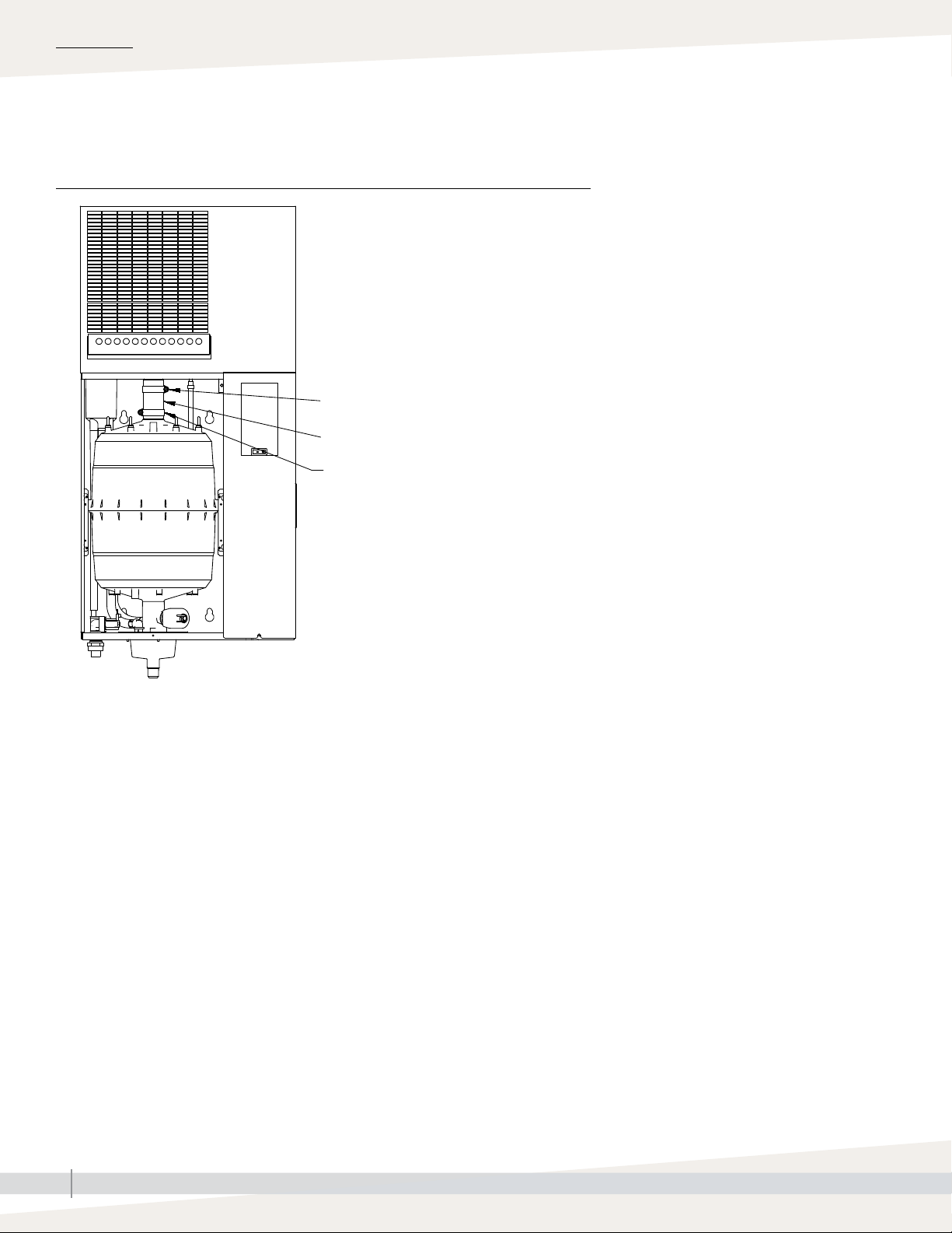
Product overview
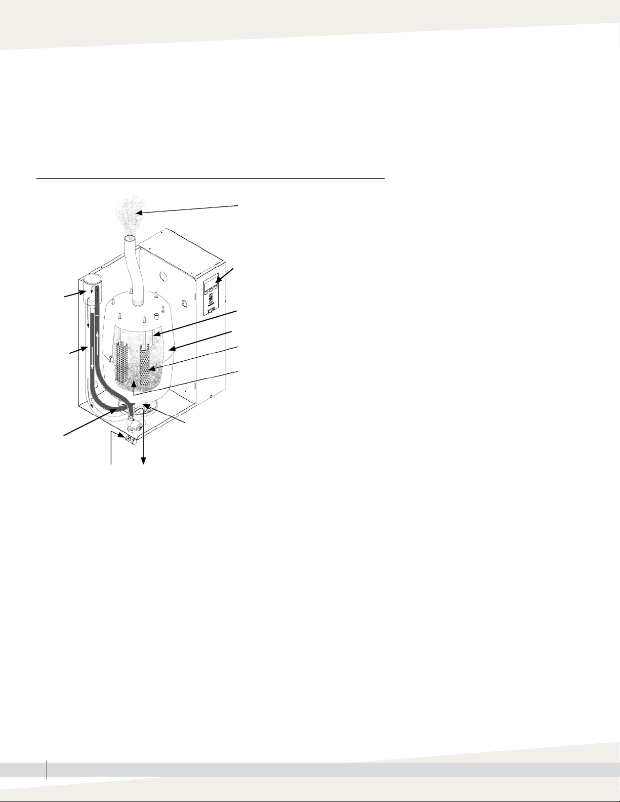
PRODUCT OVERVIEW
DriSteem XT Series electrode steam humidifiers use heat caused by electrical
resistance in their fill water to boil the fill water into humidification steam.
Steam output and water conductivity are managed via automatic draining and
filling. See Figure 2-1.
FIGURE 2-1: XT SERIES HUMIDIFIER COMPONENTS
Steam to duct or XT steam blower
(see dispersion options on Page 8)
Control panel for on-board controller
(see Figure 3-1)
Fill cup
High water sensor
Steam cylinder
Overflow
hose
Electrodes
Electrical resistance in fill water
OM-7661_aa
Download DriSteem literature
DriSteem product manuals can be
downloaded, printed, and ordered from our
website: www.dristeem.com
The Vapor-logic Installation and Operation
Manual ships with Model XTP humidifiers.
It is a comprehensive manual. Refer to it
for information about the keypad/display
and Web interface, and for troubleshooting
information.
Cylinder drain
Fill hose
Supply water connection
Note: See detailed installation drawing on Page 14 and principle of operation on Page 45.
Overflow to drain
XT SERIES INSTALLATION, OPERATION, AND MAINTENANCE MANUAL
2
Page 7
Product overview
SUPPLY WATER
There are benefits and trade-offs to consider when the application allows a
choice between hard and softened water:
Hard water: The benefit of hard water is less frequent draining and filling
than with softened water, which results in better energy and water efficiency
and more consistent steam output. However, cylinder replacement could
be more frequent with hard water, because hard water scale coats the
electrodes. The harder the water, the more frequent the need for a new
cylinder.
Softened water may be used in the XT series electrode humidifier. However,
softened water ions stay in solution to much higher concentrations than
hard water ions. The result can be more frequent draining and filling, which
results in less energy and water efficiency, and less consistent steam output.
While softened water can reduce scale build-up in the cylinder, it can also
shorten cylinder electrode life.
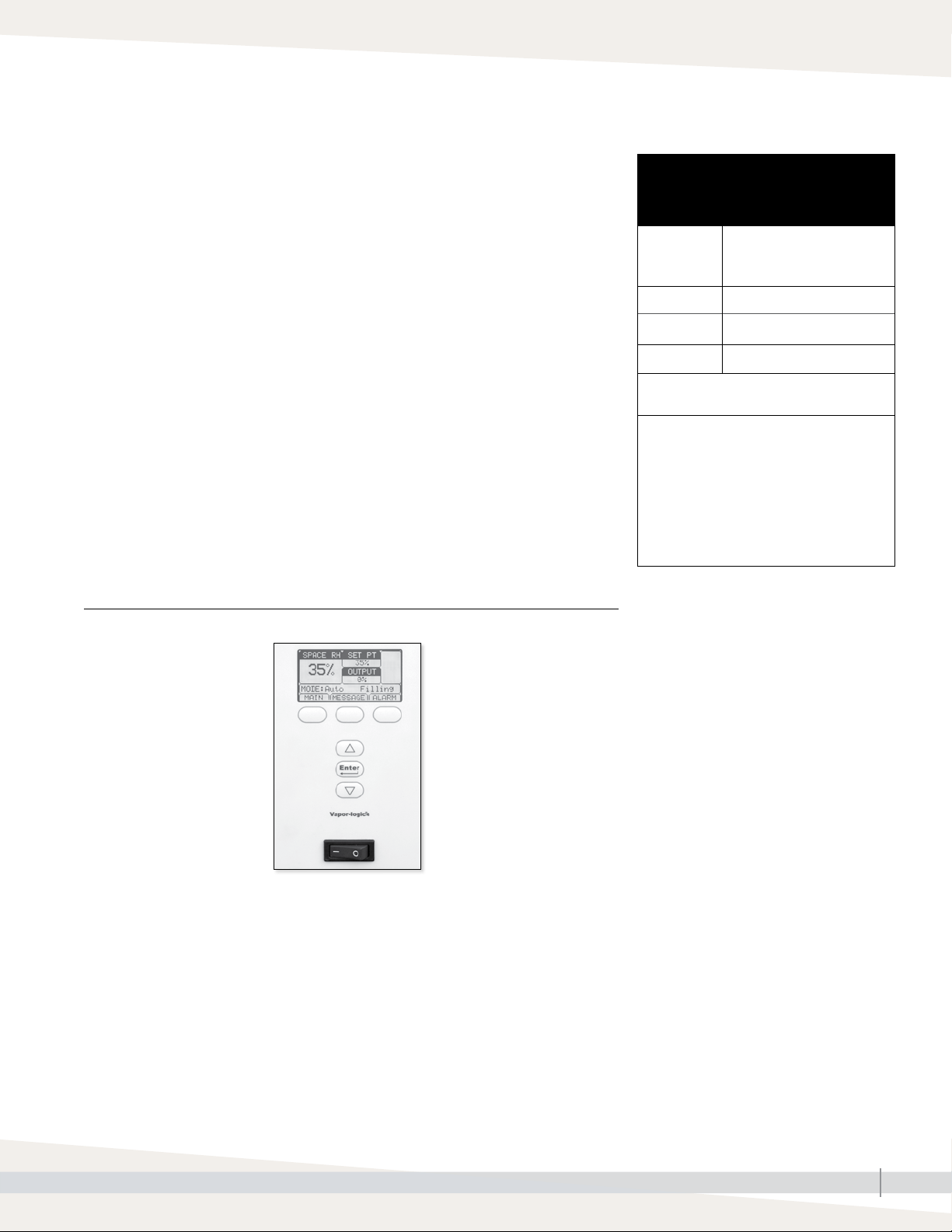
CONTROLLER
The Model XTP humidifier Vapor-logic® controller features menus for all
humidifier functions, with a Web interface for access to all functions via
Ethernet. See "Operations" beginning on page 45 for details.
FIGURE 3-1: XT SERIES HUMIDIFIER CONTROL PANEL
Table 3-1:
DriSteem supply water guidelines for
XT series electrode humidifiers
Supply water
conductivity
Chlorides Not limited
pH 6.5 to 8.5
Silica < 15 ppm
Demineralized, deionized, and reverseosmosis water cannot be used.
Supply water outside of these guidelines may
void your DriSteem warranty. Please contact
your DriSteem Representative or DriSteem
Technical Support if you need advice.
* For optimal low conductivity operation
enable the Mini Drain feature in your
Vapor-logic controller: Main > Setup > XT
management > Mini Drain > Enable.
125* to 1250 μS/cm (roughly
comparable to water hardness
of 10 to 36 grains per gallon).
XTP Vapor-logic keypad/display
Status display and
menu selection
Softkeys for direct
menu access
Navigation buttons
for item selection
Controller on-off switch*
* On-off switch for control board — not a safety shut-off to humidifier power wiring.
XT SERIES INSTALLATION, OPERATION, AND MAINTENANCE MANUAL
3
Page 8
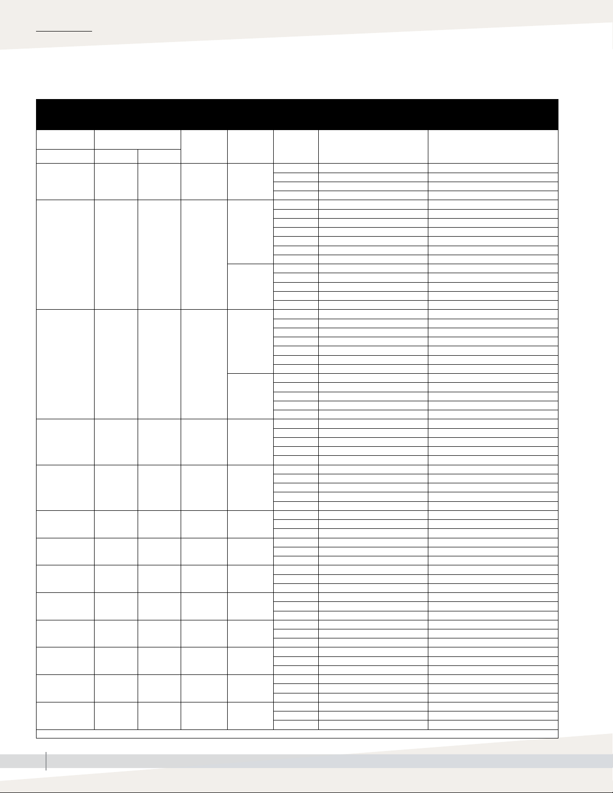
SPECIFICATIONS
Capacities, line currents, and fusing
Table 4-1:
Line currents and recommended fusing for XT Series humidifiers
Model Nominal steam capacity
XTP lbs/hr kg/h
002 5 2 1.7 1
003 10 5 3.3
006 18 8 6.0
010 30 14 10.0 3
017 50 22 16.5 3
025 75 34 25.0 3
033 100 45 33.3 3
042 125 57 41.7 3
048 143 65 47.8 3
050* 150 68 50.0 3
067* 198 90 66.7 3
083* 250 113 83.3 3
096* 287 130 95.7 3
* These models have two steam cylinders and require independent service connections.
kW Phase Volts Maximum line current (amps) Recommended fusing (amps)
120 17 25
208 10 15
230 8 15
240 8 15
208 19 25
230 17 25
1
3
1
3
240 17 25
277 14 20
400 10 13
480 8 15
600 7 10
208 11 15
240 10 15
400 6 10
480 5 10
600 4 10
208 35 45
230 31 40
240 30 40
277 26 35
400 18 25
480 15 20
600 12 15
208 20 25
240 17 25
400 10 13
480 9 15
600 7 10
208 33 45
240 29 40
400 17 25
480 14 20
600 12 15
208 55 70
240 48 60
400 29 40
480 24 35
600 19 25
400 43 63
480 36 50
600 29 40
400 58 80
480 48 70
600 39 50
400 72 100
480 60 80
600 48 70
400 80 100
480 69 90
600 55 70
400 2 x 43 2 x 63
480 2 x 36 2 x 50
600 2 x 29 2 x 40
400 2 x 58 2 x 80
480 2 x 48 2 x 70
600 2 x 39 2 x 50
400 2 x 72 2 x 100
480 2 x 60 2 x 80
600 2 x 48 2 x 70
400 2 x 80 2 x 100
480 2 x 69 2 x 90
600 2 x 55 2 x 70
XT SERIES INSTALLATION, OPERATION, AND MAINTENANCE MANUAL
4
Page 9
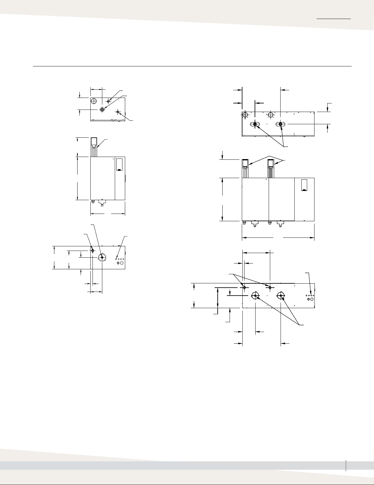
Dimensional drawings
FIGURE 5-1: XT SERIES HUMIDIFIER DIMENSIONAL DRAWINGS
SPECIFICATIONS
Top
Front
Bottom
Models XTP 002 through 048
E
Electrical knockout
D
Fill cup extension kit*
10.0 (254)
B
A
Drain outlet
Supply water
connection
C
F
D
G
E
Dispersion outlet
Electrical knockout
Electrical
knockouts
OM-7672
Top
Front
10.0 (254)
B
Bottom
Supply water connections
C
Models XTP 050 through 096
21.0 (533)
E
Dispersion outlets
Fill cup extension kits*
A
15.1 (384)
G
Electrical
knockouts
D
Notes:
* Fill cup extension (Figure 5-1) is required for the following:
- All XT Series humidifiers using Ultra-sorb or Rapid-sorb
- When developed length of steam tubing is more than 20' (6 m)
and duct static pressure exceeds 2" wc (498 Pa)
• Labeled dimensions: inches (millimeters).
• See mounting dimensions in Figure 9-1.
OM-7673
F
D
E
21.0 (533)
XT SERIES INSTALLATION, OPERATION, AND MAINTENANCE MANUAL
Drain outlets
5
Page 10
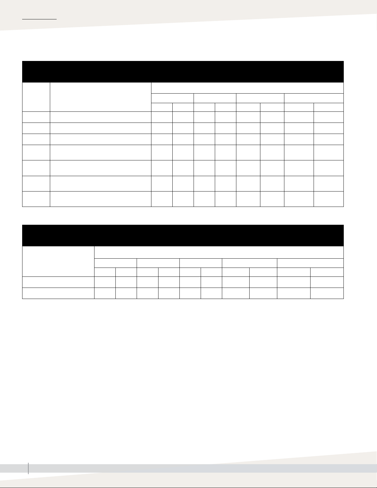
SPECIFICATIONS
Dimensions and weights
Table 6-1:
XT Series humidifier dimensions by model number
Model XTP
Dimension Description
A Cabinet width 14.6 370 17.7 450 19.9 504 39.6 1005
B Cabinet height 20.6 523 24.1 612 25.6 650 25.6 650
C Cabinet depth 8.7 221 11.8 300 13.4 340 13.4 340
Cabinet back edge to steam/drain outlet
D
centers
E Cabinet left edge to steam/drain outlet centers 4.4 112 6.0 152 7.0 178 7.0 178
Cabinet back edge to supply water connection
F
center
Cabinet left edge to supply water connection
G
center
002, 003, 006 010, 017 025, 033, 042, 048 050, 067, 083, 096
inches mm inches mm inches mm inches mm
4.5 114 6.0 152 6.7 170 6.7 170
6.7 170 9.5 241 11.1 282 11.1 282
1.0 25 1.0 25 1.1 28 1.1 28
Table 6-2:
XT Series humidifier weights by model number
Model XTP
002, 003 006 010, 017 025, 033, 042, 048 050, 067, 083, 096
lbs kg lbs kg lbs kg lbs kg lbs kg
Shipping weight 37 17 37 17 50 23 64 29 139 63
Maximum operating weight 38 17 46 21 79 36 115 52 219 99
XT SERIES INSTALLATION, OPERATION, AND MAINTENANCE MANUAL
6
Page 11
Dispersion options
SPECIFICATIONS
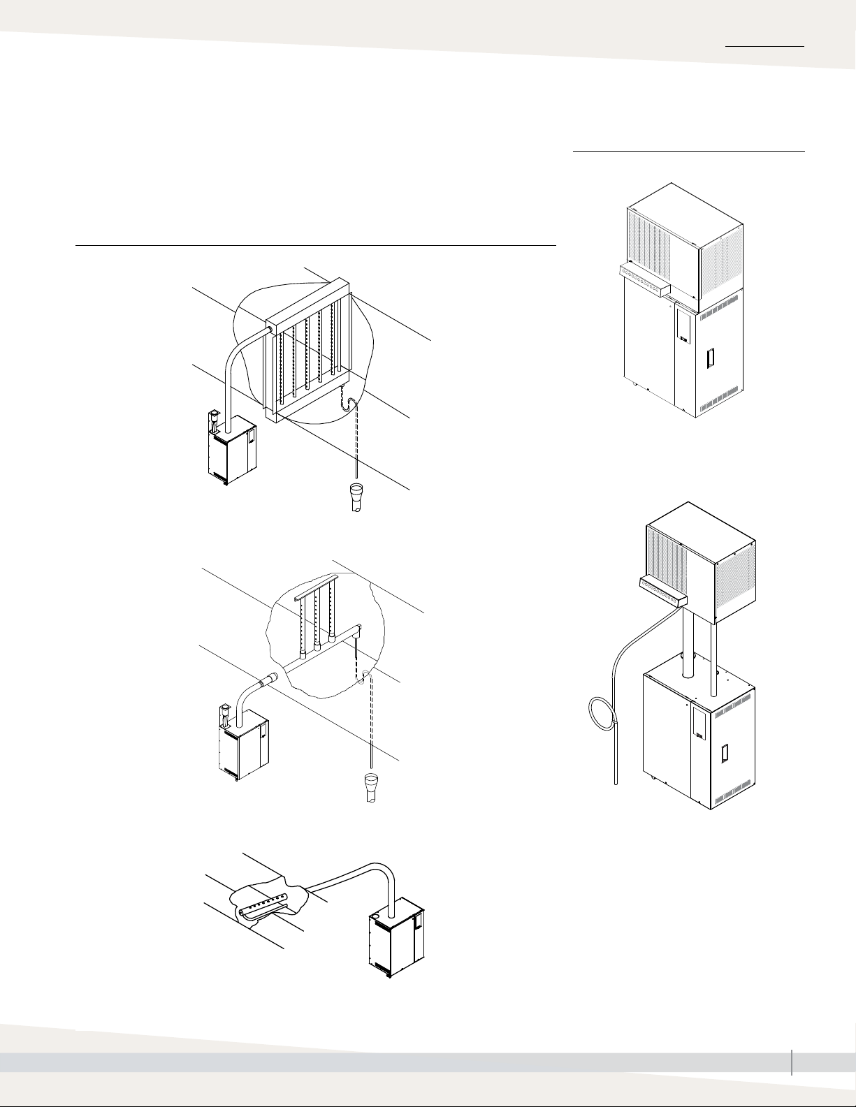
The duct dispersion options in Figure 7-1 and the open space dispersion
options in Figure 7-2 are available for XT Series humidifiers. For
installation details, see “Dispersion” beginning on Page 20.
FIGURE 7-1: XT SERIES HUMIDIFIER DUCT DISPERSION OPTIONS
Ultra-sorb
OM-7667
FIGURE 7-2: XT STEAM BLOWERS
Mounted on top of humidifier
OM-7670
Mounted up to 10' (3 m) away from
humidifier
Rapid-sorb
Single dispersion tube
OM-7668
OM-7698
OM-7669
Notes:
• Models XTP 010 and larger require condensate drain. See Page 32.
• XT steam blowers (SDU) shipped with fuses to be installed in connected XT series humidifiers.North America only
XT SERIES INSTALLATION, OPERATION, AND MAINTENANCE MANUAL
7
Page 12
INSTALLATION
Selecting a location
HUMIDIFIER
When selecting a location for the humidifier, consider the following:
• Proximity to the duct
Install the humidifier near the air duct system where the dispersion assembly
will be located. The maximum recommended length for steam hose
connecting a single humidifier to a dispersion assembly is 10' (3 m). The
maximum recommended developed length for tubing connecting a single
humidifier to a dispersion assembly is 20' (6 m).
For more information about installing dispersion assemblies, see
“Dispersion” beginning on Page 20.
• Elevation of the installed dispersion assembly
The recommended installation location for the dispersion assembly is at an
elevation higher than the humidifier. However, if the dispersion assembly
must be installed at an elevation lower than the humidifier, install a drip tee
and drain. See “Drip tee installation” on Page 29.
Before installing a dispersion assembly or interconnecting piping, review all
pitch requirements in the “Dispersion” section of this manual.
• Temperature and relative humidity (RH):
Install humidifier only in locations that meet the following temperature and
RH requirements:
- Maximum ambient temperature: 104 °F (40 °C)
- Minimum ambient temperature: 41 °F (5 °C)
- Maximum ambient humidity: 80% RH (non-condensing)
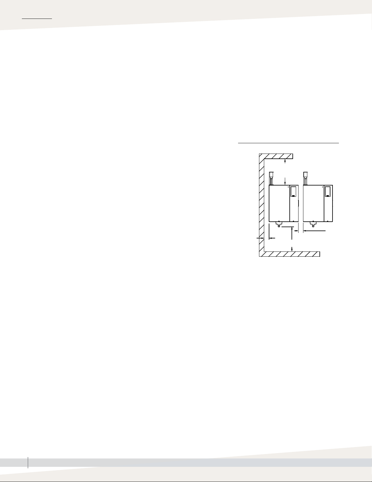
Staging multiple humidifiers
Up to four Model XTP humidifiers can be
staged to operate in sequence. In a sequenced
application, one control input signal is divided
into user-selectable control input signals for
the connected humidifiers. See the Vapor-logic
Installation and Operation Manual for
instructions on staging multiple humidifiers.
FIGURE 8-1: XT SERIES HUMIDIFIER
RECOMMENDED MINIMUM CLEARANCES
36" (914 mm)
front clearance
16"
(400 mm)
3"
(76 mm)
15" (380 mm)
3" (76 mm)
between
units
OM-7664
• Required clearances (see Figure 8-1)
• Electrical connections
Electrical power supply connections are at the lower or upper right rear
corner of the unit. See “Humidifier wiring” on Pages 17 and 18.
• Supply water and drain piping connections
Water supply piping and drain connections are at the bottom of the
cabinet. See “Piping” on Page 13.
• Exterior wall insulation
Install the humidifier on an exterior wall only if the wall is properly
insulated.
DISPERSION CONTROL DEVICES
See page 20 for recommended installation locations for the dispersion
assembly and associated control devices.
XT SERIES INSTALLATION, OPERATION, AND MAINTENANCE MANUAL
8
Page 13
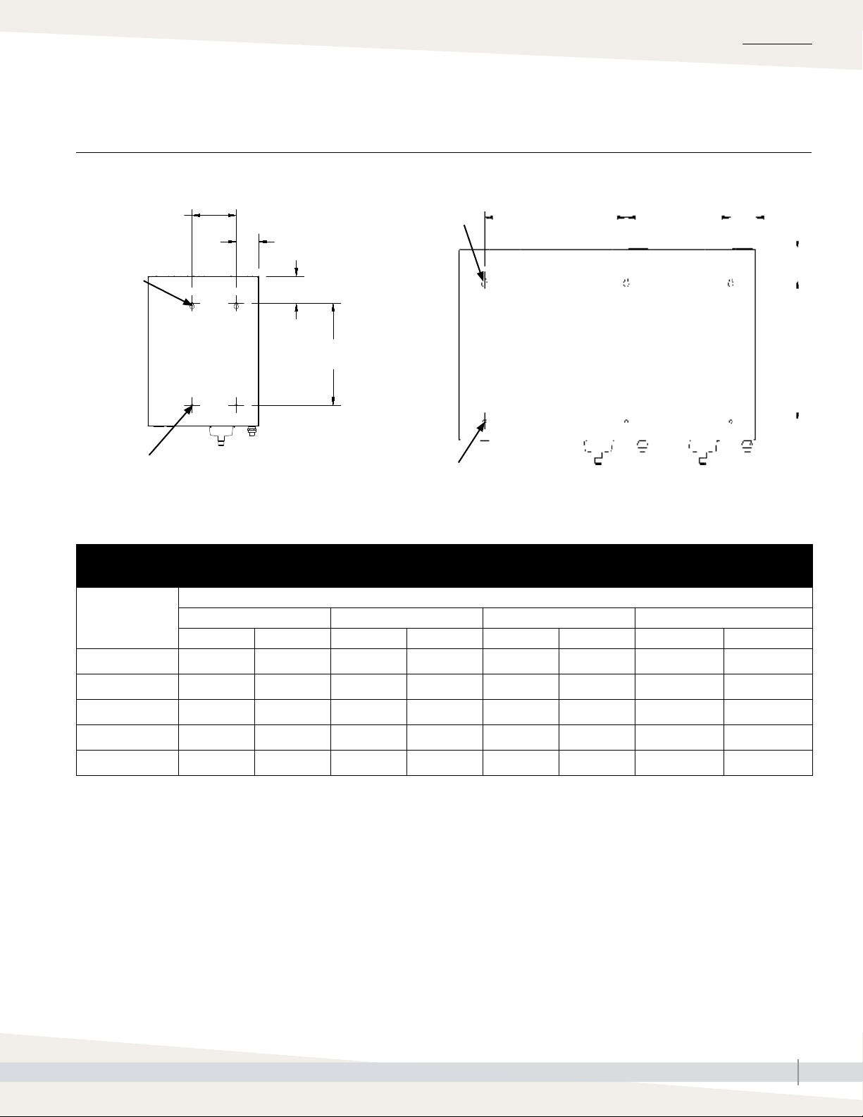
Mounting
FIGURE 9-1: XT SERIES HUMIDIFIER MOUNTING KEYHOLE LOCATIONS
INSTALLATION
Models XTP 002 through 048
A
0.390" x 0.719"
(9.9 x 18.3 mm)
dia. keyholes
0.390" (9.9 mm)
dia. holes
B
C
D
OM-7969
Table 9-1:
XT Series humidifier mounting keyhole dimensions
Dimension
A 3.9 100 7.1 180 7.5 190 14.0 356
002, 003, 006 010, 017 025, 033, 042, 048 050, 067, 083, 096
inches mm inches mm inches mm inches mm
0.390" x 0.719"
(9.9 x 18.3 mm)
dia. keyholes
0.390" (9.9 mm)
dia. holes
Model XTP
Models XTP 050 through 096
E
A
B
C
D
OM-7970-XT
B 3.0 75 3.6 92 3.4 86 3.3 84
C 3.2 81 4.4 112 4.1 104 4.1 104
D 14.0 355 16.3 414 18.9 480 18.9 480
E — — — — — — 19.0 483
XT SERIES INSTALLATION, OPERATION, AND MAINTENANCE MANUAL
9
Page 14

INSTALLATION
Mounting
Unpack the humidifier from the shipping carton, and remove the cabinet doors
and steam cylinder (see removing steam cylinder instructions below).
WARNING
Note: When first unpacking the humidifier, cut and remove the shipping strap
that goes around the cylinder and through the cylinder guides. This strap
does not need to be replaced.
REMOVING STEAM CYLINDER
If sent to this page from the “Maintenance” section, and the humidifier has
been operating, make sure the cylinder is empty and cooled before removing
it. See the shutdown and cool-down procedures on Page 49.
1. Carefully pull the electrode plugs straight up off the cylinder to ensure no
damage to the plug boot occurs.
2. Disconnect the high water sensor wire.
3. Place hands palms-down below cylinder on both sides of drain outlet.
4. Press up against bottom of cylinder with backs of hands while pressing
down against cabinet floor with fingers.
5. Raise cylinder until drain outlet clears drain valve body and the side tabs
on the cylinder have cleared the cylinder guides. Remove cylinder from
cabinet.
WALL MOUNTING HUMIDIFIER
Mount the humidifier level and plumb using the lag bolts provided. Follow the
instructions below for mounting on a wood stud wall.
Mounting hazard
Mount humidifier per the instructions
in this manual and to a structurally
stable surface. Improper mounting of
the humidifier can cause it to fall or tip,
resulting in severe personal injury or
death.
1. Mount spanner boards on wall, spanning at least two studs. Position one
board at top of cabinet (for the lag bolts), and other board at bottom of
cabinet.
2. Predrill pilot holes in spanner boards, and secure humidifier to spanner
boards with lag bolts.
Note: Use the appropriate mounting methods and mounting hardware for other
wall types.
XT SERIES INSTALLATION, OPERATION, AND MAINTENANCE MANUAL
10
Page 15
Fill cup extension kit
INSTALLATION
A fill cup extension (Figure 11-1) is required for the following:
• All XT Series humidifiers using Ultra-sorb or Rapid-sorb
• When developed length of steam tubing is more than 20' (6 m) and duct
static pressure exceeds 2" wc (498 Pa)
REMOVING EXISTING FILL CUP
Remove the existing fill cup as follows:
1. Remove steam cylinder from XT cabinet (if not already out).
2. Expand spring clamps and slide them up cylinder fill hose and supply
water hose, and disconnect hoses from cylinder fill hose connection and
fill valve adapter.
3. Disconnect overflow hose from overflow elbow.
4. Remove fill cup and hoses (fill cup is press fit into top of XT cabinet).
INSTALLING FILL CUP EXTENSION KIT
1. Remove steam cylinder(s) from XT cabinet (if not already out).
2. Route fill cup extension kit hoses into cabinet through fill cup hole, and
fasten extension bracket as shown with two screws provided.
3. Route hoses along back of cabinet interior to provide clearance for
cylinder.
FIGURE 11-1: FILL CUP EXTENSION KIT
Fill cup
(see inset below)
Overflow
hose (C)
Supply
water
hose (A)
Fill valve
Cylinder fill
hose (B)
Overflow
elbow
Drain cup
plate
Cylinder fill
hose connection
OM-7690
Fill cup
4. Cut supply water hose (small-diameter hose) (A) to length so it can attach
to fill valve adapter without kinking.
5. Expand spring clamp and slide it onto supply water hose (A) far enough
so it will not interfere, then push hose onto fill valve adapter. Expand and
slide spring clamp into place.
6. Cut cylinder fill hose (bottom, center hose) (B) to length so it can attach to
cylinder fill hose connection without kinking.
7. Expand spring clamp and slide it onto cylinder fill hose (B) far enough
so it will not interfere, then push hose onto cylinder fill hose connection.
Expand and slide spring clamp into place.
8. Cut overflow hose (C) to length so it can attach to overflow elbow
without kinking.
9. Push overflow hose onto overflow elbow. Spring clamp is not required on
this connection.
Supply water (A)
Cylinder fill (B)
1" air gap
Overflow (C)
OM-7629
XT SERIES INSTALLATION, OPERATION, AND MAINTENANCE MANUAL
11
Page 16
INSTALLATION
Steam cylinder
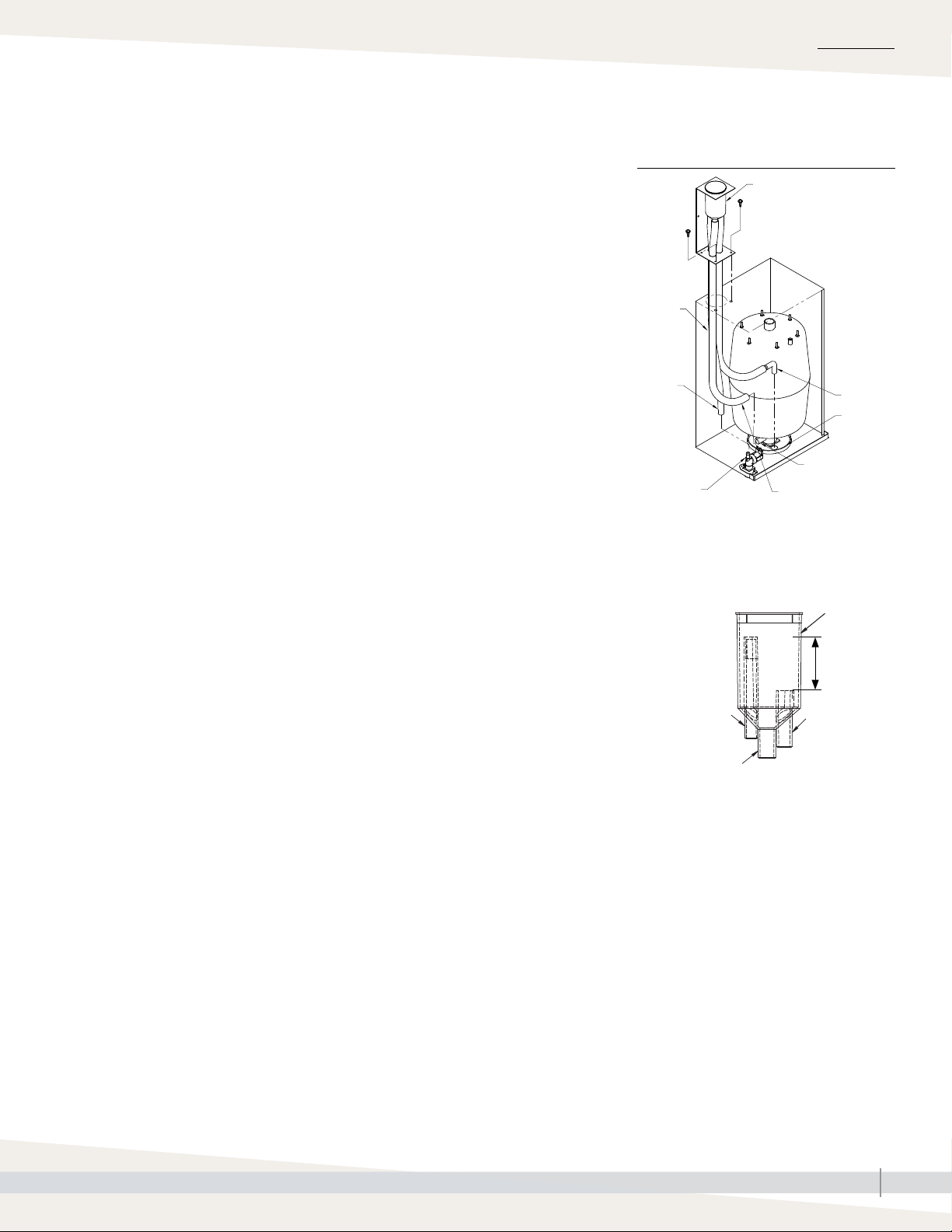
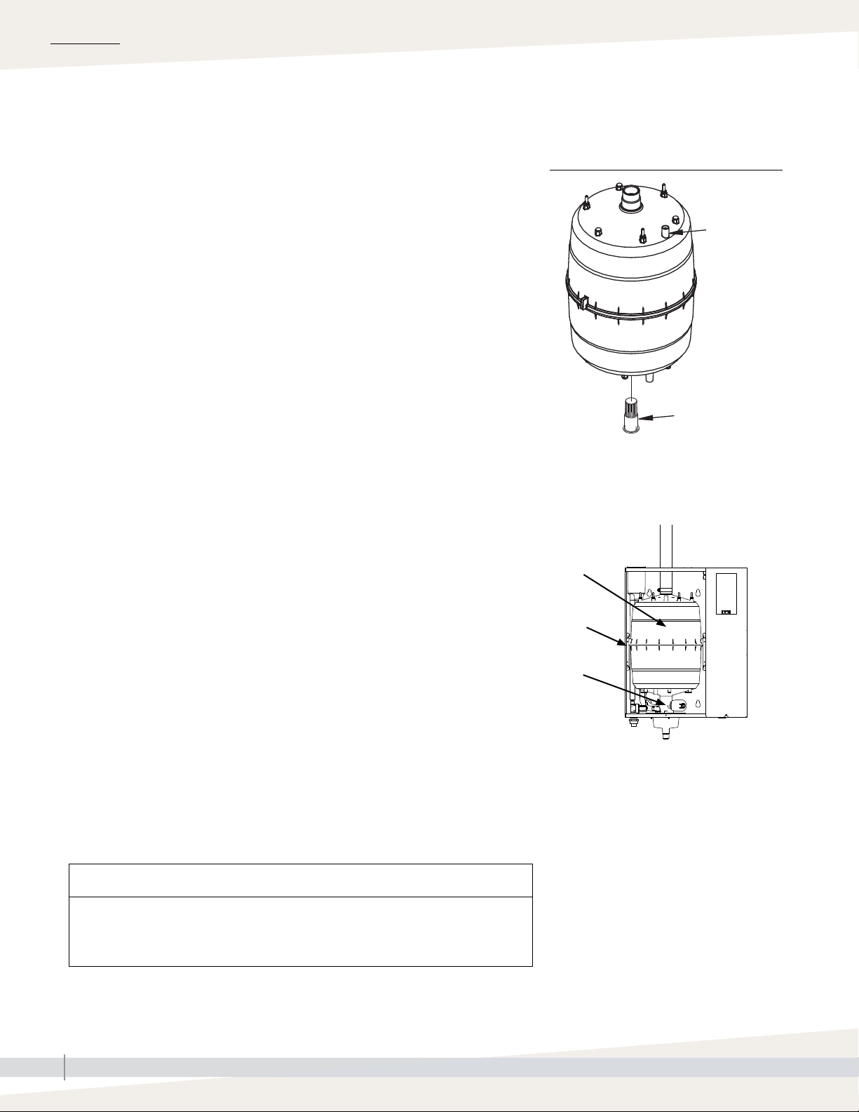
INSTALLING STEAM CYLINDER
1. Make sure strainer is pressed into steam cylinder drain outlet and strainer
flange is flush with bottom of cylinder outlet. See Figure 12-1.
2. Use water to lubricate drain outlet on bottom of cylinder and O-ring in
drain valve body. See Figure 12-1.
Note: Because of tight clearances, perform Steps 3 through 4 only if servicing
Models XTP 002 through 017 with top-mounted steam blower. For all
other models, skip to Step 5.
3. Slide steam hose that connects to cylinder and steam blower up
until it is engaged on steam inlet of steam blower and tight against
bottom of steam blower.
4. Slide steam outlet of new cylinder all the way up into open end of
steam hose from Step 3.
5. With Warning label on cylinder facing you, lower cylinder drain outlet into
drain valve body, and rotate cylinder so side tabs line up with cylinder
guides inside cabinet. Push down on cylinder until drain outlet is fully
seated in drain valve body.
6. Slide steam hose down so it is fully engaged on cylinder steam outlet.
Re-install hose clamp(s).
FIGURE 12-1: STEAM CYLINDER
INSTALLATION
High water
sensor pin
OM-7632
Strainer
7. Connect high water sensor (yellow) wire to single pin surrounded by
plastic shoulder on cylinder.
8. Connect electrode wires to pins on top of cylinder. Make sure all plugs fit
snugly and are fully engaged on pins.
Important: Three phase cylinders have color-coded dots on the cylinder
and color bands on the electrode plugs. When connecting the plugs, match
the band colors on the plugs with the dot colors on the cylinder. Refer to the
wiring diagram shipped with the humidifier if necessary.
CAUTION
If cylinder plugs become loose, damage to the humidifier may occur. Obtain
replacement plugs from DriSteem. See “Replacement parts” on Pages 57 and
59 for part numbers.
Warning
label
Cylinder
guide
Drain valve
body
OM-7972-XT
XT SERIES INSTALLATION, OPERATION, AND MAINTENANCE MANUAL
12
Page 17
INSTALLATION
Piping:
SUPPLY WATER PIPING
Supply water and drain
Use only copper for supply water piping; do not use rubber or plastic. The
standard supply water connection before the fill valve is a 3/4" FIP.
Note: The supply water connection size is 3/4"BSP [DN20] in Europe.
In cases where water hammer may be a possibility, consider installing a shock
arrestor. Water pressure must be 25 to 80 psi (175 to 550 kPa).
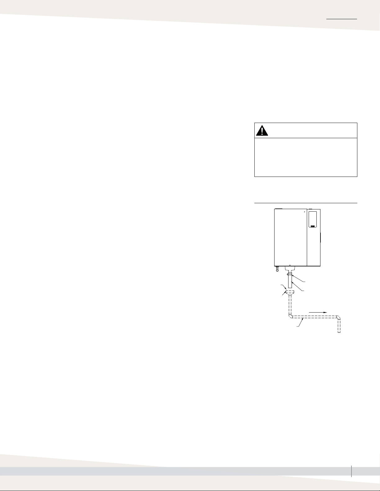
DRAIN PIPING
Drain piping must be code-approved, 3/4" (DN 20) ID material rated for
212 °F (100°C) minimum.
The drain cup has an integral grounding plate and requires a field-installed
1" (25 mm) air gap to a drain funnel to prevent conduction of electricity in the
drain line.
The XT Series humidifier features user-selectable drain water tempering. When
drain water tempering is selected, the humidifier tempers drain water by
opening the fill valve whenever the drain valve is energized to cool drain water
before it enters the drain. Drain water tempering keeps water entering the
drain line less than 140°F (60°C). Manually energizing the drain valve when
the supply water is shut off can allow 212 °F (100 °C) water to enter the drain
line.
Important: Thoroughly flush supply
water piping to remove pipe residue and
stagnant water before connecting piping to
humidifier. Pipe residue and stagnant water
in water supply piping can cause foaming,
preventing humidifier from reaching required
steam capacity.
WARNING
Hot drain pipes
Drain piping surface may be hot.
Touching or contact with hot pipe may
cause severe personal injury.
FIGURE 13-1: DRAIN PIPING DETAIL
Observe the following precautions when selecting and installing drain piping
to ensure personal safety and material integrity:
• When using copper or other metallic drain piping, ground the drain piping
to the earth ground lug in the XT Series humidifier.
• Chlorinated polyvinyl chloride (CPVC) piping is a non-metallic alternative
for drain piping. It is rated up to 212°F (100°C) for intermittent-use, lowpressure applications.
The connection size for the steam cylinder drain is 1" (DN25) hose. Do not
reduce this connection size. If drainage by gravity is not possible, use a
reservoir pump rated for 212 °F (100 °C) water.
The open drain must be at least 12” (300 mm) below the bottom of the XT
humidifier, to help prevent steam condensation on the humidifier. Use the 12”
(300 mm) drain hose provided and position above field-installed open drain.
Alternately, route drain line away from beneath humidifier to open drain. See
Figure 13-1.
AUTOMATIC DRAIN WATER TEMPERING
XT Series humidifiers are shipped with drain water tempering set to ON for
North America (OFF for Europe). To activate automatic drain water tempering
see the Vapor-logic Installation and Operation Manual.
OM-7591
1" (25 mm)
air gap
Open drain
3/4" (DN20) I.D.
* Ships with humidifier
• Dashed lines indicate provided by installer
• The open drain must be at least 12”
(300 mm) below the bottom of the
XT humidifier, to help prevent steam
condensation on the humidifier.
Hose clamp*
Drain hose*
Pitch 1/8"/ft (1%)
toward drain
To drain
XT SERIES INSTALLATION, OPERATION, AND MAINTENANCE MANUAL
13
Page 18
INSTALLATION
Piping:
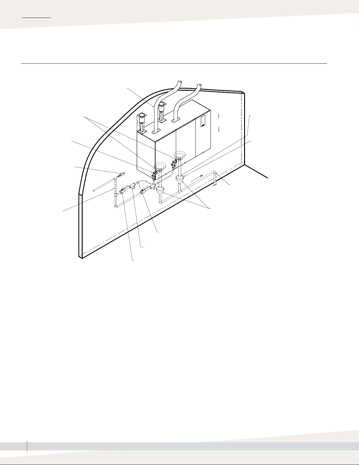
FIGURE 14-1: XT SERIES HUMIDIFIER FIELD PIPING OVERVIEW
Drain hose and clamp*
Fill valve with 3/4" FIP
(3/4"BSP [DN20] in
Europe) supply water
connection
Metallic water
supply line
Field piping overview
Steam hose or tubing. DriSteem
recommends tubing for runs longer than
10' (3 m). See Table 26-1 for maximum
tubing lengths. Tubing must be grounded.
Shock arrester
(by installer)
recommended
to reduce water
hammer
Install
plumb
Pitch 1/8"/ft (1%) toward drain
Floor
drain
3/4" (DN20) drain piping up to
second drain connection
1¼" (DN32) drain piping after
second drain connection, or if
piping run is over 10’ (3 m).
1" (25 mm) air gap required to
isolate unit drain piping from
sanitary drain piping. Locate air
gap only in spaces with adequate
temperature and air movement to
absorb flash steam, or condensing
on nearby surfaces could occur.
Open drains required directly
below humidifier drains to prevent
downstream drain line blockage
from causing water to back up into
cylinder. Refer to governing codes
for drain pipe size and maximum
discharge water temperature. Install
spill funnels plumb to floor drain.
Notes:
• Dashed lines indicate provided by installer.
• Two-cylinder model shown.
* Ships with humidifier
3/4" (DN20) copper water supply line; water
pressure must be 25 to 80 psi (175 to 550 kPa).
Inlet strainer, by installer
Supply valve, by installer
OM-7666
XT SERIES INSTALLATION, OPERATION, AND MAINTENANCE MANUAL
14
Page 19
INSTALLATION
Piping:
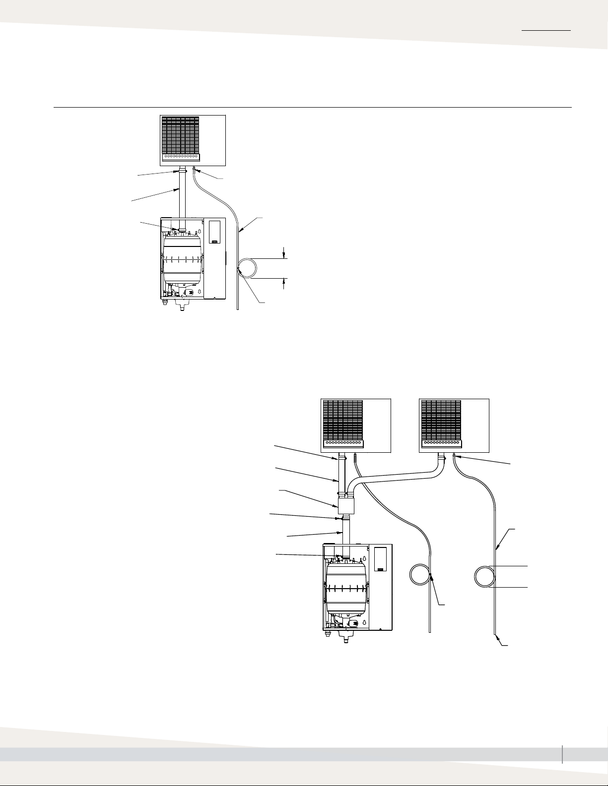
FIGURE 15-1: PIPING FROM XT SERIES HUMIDIFIER TO REMOTE XT STEAM BLOWER
Hose clamp (provided)
Steam hose
(purchased separately
from DriSteem)
Hose clamp (provided)
XT steam blowers
Plastic tie
OM-7974
To open drain or humidifier fill cup.
Water seal is required, whether condensate is piped to
open drain or returned to humidifier fill cup.
Notes:
• Maximum recommended distance between humidifier
and XT steam blower is 10’ (3 m).
• Models XTP 042 through 096 are not intended for use
with a steam blower.
Condensate hose (purchased
separately from DriSteem)
7” (178 mm) water seal
Plastic tie
Hose clamps
(provided)
Steam hose
(purchased separately from DriSteem)
Stainless steel Y connector*
Hose clamp*
Steam hose*
Hose clamp*
* Provided in optional connector
kit Part No. 191070-102
OM-7975
Model XTP 025 only
Plastic tie
Condensate
hose
(purchased
separately
from DriSteem)
7” (178 mm)
water seal
Plastic tie
To open drain or
humidifier fill cup.
Water seal is
required, whether
condensate is
piped to open
drain or returned
to humidifier fill
cup.
XT SERIES INSTALLATION, OPERATION, AND MAINTENANCE MANUAL
15
Page 20
INSTALLATION
Piping: XT steam blowers
FIGURE 16-1: PIPING FROM XT SERIES HUMIDIFIER TO TOP-MOUNTED XT STEAM
BLOWER
Hose clamp (provided)
Steam hose (provided)
Hose clamp (provided)
OM-7976
Notes:
• Maximum recommended distance between humidifier and XT steam blower is 10’ (3 m).
• Models XTP 025 and 033 are not intended for use with a direct-mounted steam blower.
• Models XTP 042 through 096 are not intended for use with a steam blower.
XT SERIES INSTALLATION, OPERATION, AND MAINTENANCE MANUAL
16
Page 21
Humidifier wiring
All wiring must be code approved and in accordance with the unit wiring
diagram. Power supply wiring must be rated for 105 °C. See Figure 17-1
for the humidifier wiring diagram locations.
When selecting a location for installing the humidifier:
• Avoid areas close to sources of electromagnetic emissions such as power
distribution transformers.
• Do not loop power wiring.
• Do not use aluminum wire.
CONDUIT KNOCKOUTS
Conduit and control wiring knockouts are provided on the XT Series humidifier
cabinet. See Figure 5-1.
INSTALLATION
WARNING
Electric shock hazard
Only qualified electrical personnel
should perform field wiring installation
procedures. Improper wiring or contact
with energized circuits may cause
property damage, severe personal
injury, or death as a result of electric
shock and/or fire.
CONTROL COMPONENT PLACEMENT
Follow the guidelines on Page 19 for placing humidistats, transmitters, and
airflow proving switches.
CAUTION
Adding conduit connections not recommended
Adding alternate conduit connections is not recommended. If you must make
additional holes in the humidifier cabinet, protect all internal components from
debris, and vacuum out the cabinet when finished. Failure to follow these precautions
can damage sensitive electronic components and void the DriSteem warranty.
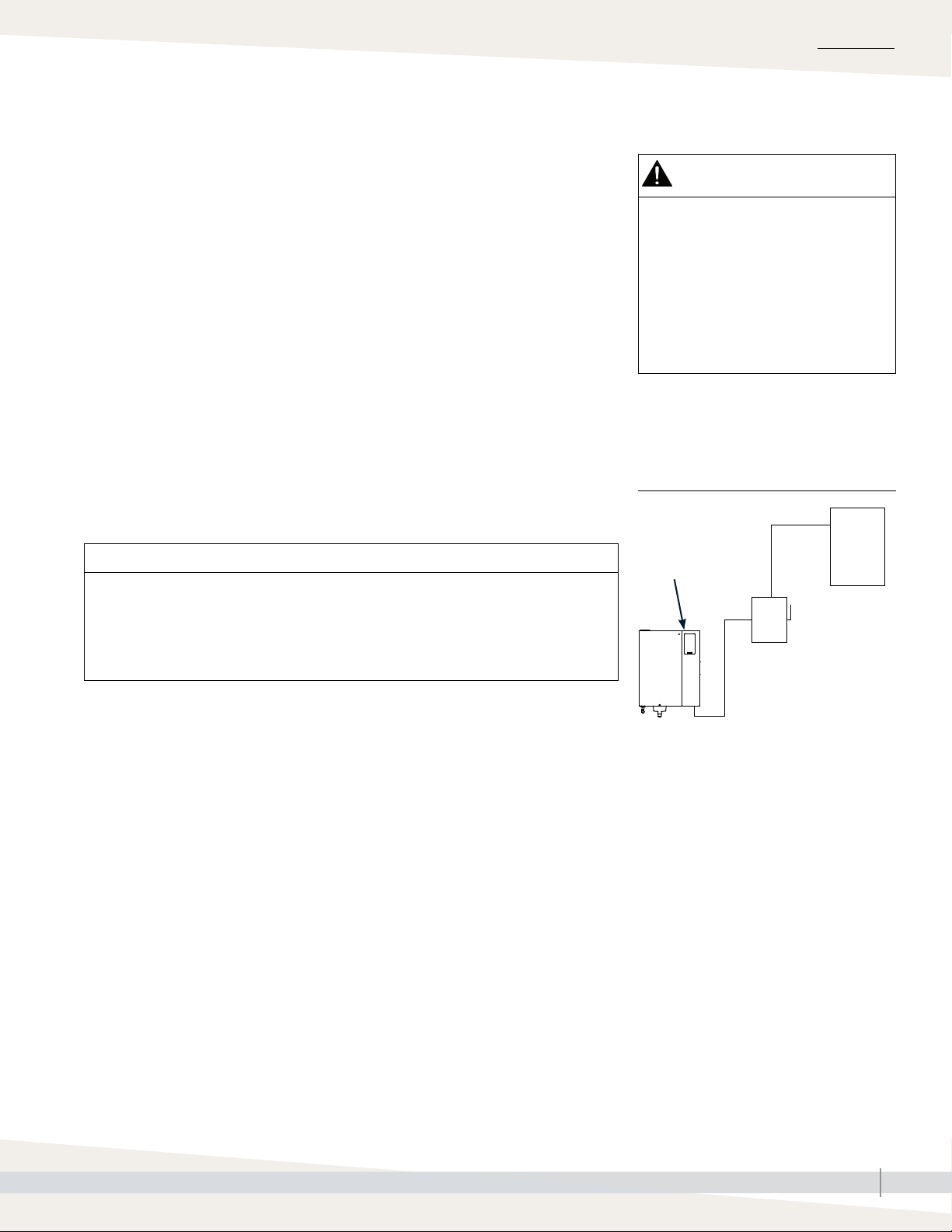
FIGURE 17-1: FIELD WIRING
REQUIREMENTS
Wiring
diagram
inside of
humidifier
cabinet
Power supply
Fused disconnect
OM-7692
XT Series humidifier
Notes:
• Control wiring and power wiring must be
run in dedicated or separate earthed metal
conduit, cable trays, or trunking.
• Separate the line voltage wiring from low
voltage control circuit wiring when routing
electrical wiring inside the humidifier
cabinet.
• Do not use chassis or safety grounds as
current-carrying commons. Never use a
safety ground as a conductor or neutral to
return circuit current.
• For circuit protection requirements, see
recommended fusing in Table 4-1.
XT SERIES INSTALLATION, OPERATION, AND MAINTENANCE MANUAL
17
Page 22

INSTALLATION
Humidifier wiring
CONNECTION INSTRUCTIONS
Before connecting power, refer to the wiring diagram or the data plate on the
outside of the cabinet for wire sizing amperage.
For control signal wiring from a humidistat, transmitter, or signal by others, see
the wiring diagrams shipped inside the humidifier.
See “Step 1 – Field wiring” in the Vapor-logic Installation and Operation
Manual for detailed instructions on the following:
• Control input wiring:
See the “Control input” section.
• Duct airflow proving switch and duct high limit humidistat wiring
(recommended optional devices):
See the following sections:
“Airflow proving switch” and
“Duct high limit switch or transmitter”
• Remote signal wiring:
See the following sections:
“Programmable triac” and
“Programmable relay (dry contact)”
EARTH GROUNDING REQUIREMENTS
A code-approved safety earth grounding system is required. The ground
connection must be made with solid metal-to-metal connections. Ground wire
should be the same size as power wiring.
UNITS WITH STEAM BLOWER
Steam blowers (SDUs) receive power for operation from the XT series
humidifier. For North America only: Install 2 fuses in the XT unit to provide
power to the steam blower. Fuses are shipped with the steam blower.
Replacements available from DriSteem.
WARNING
Excessive moisture hazard
DriSteem strongly recommends
installing a duct airflow proving switch
and a duct high limit humidistat. These
devices prevent a humidifier from
making steam when there is low airflow
in the duct or when the RH level in the
duct is too high. Failure to install these
devices can result in excessive moisture
in the duct, which can cause bacteria
and mold growth or dripping through
the duct.
Proper wiring prevents electrical noise.
Electrical noise can produce undesirable effects
on electronic control circuits, which affects
controllability. Electrical noise is generated
by electrical equipment, such as: inductive
loads, electric motors, solenoid coils, welding
machinery, or fluorescent light circuits. The
electrical noise or interference generated from
these sources (and the effect on controllers)
is difficult to define, but the most common
symptoms are erratic control or intermittent
operational problems.
Important:
• For maximum EMC effectiveness, wire all
humidity, high limit, and airflow controls
using multicolored shielded/screened
plenum-rated cable with a drain wire for
the shield/screen. Connect the drain wire
to the shield/screen ground terminal with
wire less than 2" (50 mm) in length.
• Do not ground shield at the device end.
XT SERIES INSTALLATION, OPERATION, AND MAINTENANCE MANUAL
18
Page 23

Sensor placement
INSTALLATION
SENSOR LOCATION IS CRITICAL
Sensor location has a significant impact on humidifier performance. See the
recommendations below and Figure 19-1.
Note: DriSteem recommends that you do not interchange room and duct
humidity devices. Room humidity devices are calibrated with zero or little
airflow, whereas duct humidity devices require air passing across them.
Recommended humidity control (transmitter/humidistat) locations:
A. Ideal. Ensures the best uniform mix of dry and moist air with stable
temperature control.
B. Acceptable, but room environment can affect controllability, such as when
sensor is too close to air grilles, registers, or heat radiation from room
lighting.
C. Acceptable. Provides uniform mixture of dry and moist air. If extended time
lag exists between humidity generation and sensing, extend sampling time.
D. Acceptable (behind wall or partition) for sampling entire room if sensor is
near an air exhaust return outlet. Typical placement for sampling a critical
area.
E. Not acceptable. These locations might not represent actual overall
conditions in the space.
Other factors affecting humidity control
Humidity control involves more than the
controller’s ability to control the system. Other
factors that play an important role in overall
system control are:
• Size of humidification system relative to
load
• Overall system dynamics associated with
moisture migration time lags
• Accuracy of humidistats and humidity
transmitters and their location
• Dry bulb temperature accuracy in space
or duct
• Velocities and airflow patterns in ducts
and space environments
• Electrical noise or interference
F. Not acceptable. Do not place sensors near windows, door passageways,
or areas of stagnant airflow.
Recommended safety (airflow and high limit) sensor location:
G. Best sensing location for high limit humidistat or humidity sensor and airflow
proving switch.
FIGURE 19-1: RECOMMENDED SENSOR LOCATIONS
Outside air
Relief air
Damper control
Return air
Window
E
•
A
•
Air handling
C
•
Wall or partition
unit
•
8' to 12'
(2.4 m to 3.7 m)
min.
G
•
D
•
B
E
•
High limit humidistat or high limit transmitter
(set at 90% RH maximum)
Airflow switch or differential pressure
switch (sail type recommended for VAV
applications)
Vapor absorption has taken place
Point of vapor absorption
Humidifier dispersion assembly
Turning vanes
F
Doorway
E
•
F
Window
DC-1084
XT SERIES INSTALLATION, OPERATION, AND MAINTENANCE MANUAL
19
Page 24

INSTALLATION
Dispersion:
DriSteem humidifiers operate with several types of dispersion assemblies for
open spaces and for ducts and air handling units.
Dispersion assemblies in ducts and air handling units must be positioned where
the water vapor being discharged is carried off with the airstream and is
absorbed before it can cause condensation or dripping.
• In general, the dispersion assembly is best placed where the air can absorb
the moisture being added without causing condensation at or after the unit.
This normally will be after the heating coil or where the air temperature is
highest.
Selecting the dispersion assembly location
XT SERIES INSTALLATION, OPERATION, AND MAINTENANCE MANUAL
20
Page 25

INSTALLATION
Dispersion:
• Place the dispersion assembly such that absorption will occur:
– before the intake of a high efficiency filter, because the filter can remove
the visible moisture and become waterlogged;
– before coming in contact with any metal surface;
– before fire or smoke detection devices;
– before a split in the duct; otherwise, the dispersion assembly can direct
more moisture into one duct than the other.
• When draining dispersion condensate to an open drain, provide a 1"
(25 mm) air gap between the condensate drain piping and the drain.
Locate the gap only in spaces with adequate temperature and air movement
to absorb flash steam; otherwise, condensation may form on nearby
surfaces.
Selecting the dispersion assembly location
WARNING
Hot surface and steam hazard
Dispersion assembly and steam hose or
tubing can contain steam, and surfaces
can be hot. Discharged steam is not
visible. Contact with hot surfaces or air
into which steam has been discharged
can cause severe personal injury.
XT SERIES INSTALLATION, OPERATION, AND MAINTENANCE MANUAL
21
Page 26

INSTALLATION
Dispersion:
CONDENSATE RETURN GUIDELINES
Returning condensate to steam cylinder
To prevent overfilling the steam cylinder, follow the condensate guidelines
below:
• When condensate can be returned to the steam cylinder:
– Single dispersion tube
– Up to 20 lbs/hr (9.1 kg/h) of steam production
– 10' (3 m) or less of steam hose between humidifier and dispersion
– 20' (6 m) or less of tubing between humidifier and dispersion
• When condensate should be wasted to the drain:
– Ultra-sorb or Rapid-sorb dispersion
– Single dispersion tube with condensate drain
– Single dispersion tube with:
- More than 20 lbs/hr (9.1 kg/h) or more of steam production, or
- More than 10' (3 m) of steam hose between humidifier and
dispersion
- More than 20' (6 m) of tubing between humidifier and dispersion
XT Series humidifier steam outlet
The steam outlet on the humidifier is sized
to the output of the humidifier. DO NOT use
interconnecting steam hose or tubing with an
inside diameter smaller than the humidifier
steam outlet. Reducing the inside diameter will
result in the internal humidifier system pressure
exceeding the parameters for acceptable
performance.
• See maximum steam carrying capacities in
Table 26-1 and 27-1.
• If the humidifier must be located higher
than the dispersion assembly, use the
recommended installation shown in Figure
29-1.
XT SERIES INSTALLATION, OPERATION, AND MAINTENANCE MANUAL
22
Page 27

INSTALLATION
Dispersion:
FIGURE 23-1: STEAM OUTLET CONNECTIONS, MODELS XTP 002 THROUGH 025
Connector
(optional)*
See Caution
below
Steam outlet connections
Models XTP 002 through 006
To dispersion assembly
1½” (DN40) steam hose
1” (DN25) steam hose,
12" (305 mm) long
(optional)*
Hose clamp
(optional)*
Models XTP 010 through 025
To dispersion assembly
1½” (DN40) I.D.
steam hose**
Hose clamp**
XT series
humidifier
OM-7674
* Provided in optional connector kit Part No. 191070-100 (see Table 61-1)
** Provided by installer.
OM-7675
CAUTION
Connector kit location
Install the connector for increasing from 1” to 1½” (DN25 to DN40) hose or tube immediately above the XT Series humidifier as
shown above.
Failure to install the connector kit immediately above the humidifier will cause system pressure fluctuations and increase cylinder
pressure, steam velocity, and condensate noise.
XT SERIES INSTALLATION, OPERATION, AND MAINTENANCE MANUAL
23
Page 28

INSTALLATION
Dispersion:
FIGURE 24-1: STEAM OUTLET CONNECTIONS WITH HOSE, MODELS XTP 033 THROUGH XTP096 WITHIN 10' (3 M) OF
DISPERSION ASSEMBLY
Steam outlet connections with hose
WARNING
Preventing back pressure/abnormal operation in dual cylinder humidifiers and installations where two individual units are
connected to a single dispersion panel.
Read and follow all steam hose installation instructions. Failure to follow these instructions could result in excessive back pressure or
abnormal operation of the unit. Severe personal injury or damage to the unit may result.
Models XTP 033, 042, and 048
To dispersion assembly
2" (DN50)
steam hose,
10' (3 m)
maximum
Stainless steel hose connector*
Hose clamp*
1½" (DN40) steam hose*,
12" (305 mm) long
Notes:
• For horizontal runs longer than 5' (1.5 m) or vertical runs long than 10'
(3m), tubing is required. Do not use steam hose.
• See Table 61-1 for optional kits listed below.
* Provided in optional connector kit Part No. 191070-101
** Provided in optional connector kit Part No. 191070-002
*** Provided in optional connector kit Part No. 162825-202F
OM-7979-XT
Models XTP 067 through 096
3" (DN80) flange connection***
attaches directly to dispersion
2" (DN50) steam hose. Each cylinder
to connect to dispersion separately. For
distance greater than 10', use hard pipe.
Stainless steel hose connector*
Hose clamp*
1½" (DN40) steam hose*,
12" (305 mm) long
Model XTP 050
Hose clamp**
Stainless steel tube connector**
Steam hose** attaches directly to
dispersion, 2" (DN50) on Ultra-sorb and
Rapid-sorb
1½" (DN40) steam hose. Each cylinder
to connect to dispersion separately. For
distance greater than 10', use hard pipe.
OM-7980-XT
OM-7981
XT SERIES INSTALLATION, OPERATION, AND MAINTENANCE MANUAL
24
Page 29

INSTALLATION
Dispersion:
FIGURE 25-1: CONNECTING TWO CYLINDERS TO A DISPERSION ASSEMBLY
2" (DN50) steam hose connection
1½" (DN40) hose connections
from two cylinders
Steam outlet connections with hose
OM-7913
WARNING
Preventing back pressure/abnormal
operation in dual cylinder humidifiers
and installations where two individual
units are connected to a single
dispersion panel.
Read and follow all steam hose
installation instructions. Failure to
follow these instructions could result in
excessive back pressure or abnormal
operation of the unit. Severe personal
injury or damage to the unit may result.
3" (DN80) flange connection
2" (DN50) hose connections
from two cylinders
OM-7914
Notes:
• For two cylinders, connect the stainless steel tube connector directly to the dispersion inlet as shown.
The diameter and pitch of the tube connector must match the inlet diameter and pitch of the dispersion unit.
• Always run separate steam hose/tubing from each cylinder to the connection of the dispersion device.
Only connect a maximum of two cylinders to any single dispersion unit.
XT SERIES INSTALLATION, OPERATION, AND MAINTENANCE MANUAL
25
Page 30

INSTALLATION
Dispersion:
Interconnecting piping requirements
Condensate control and collection
Controlling condensate flow and collection
in an XT Series humidifier system is critical
to performance. To maximize humidifier
performance:
• See Table and 26-1.
• Follow all installation recommendations
for your specific humidifier and
dispersion assembly from here through
Page 44.
Table 26-1:
Maximum steam carrying capacity and length of interconnecting steam hose and tubing for
Models XTP 002 through XTP096
DriSteem steam hose*
Model
Hose I.D.
XTP inches DN lbs/hr kg/h ft m inches DN lbs/hr kg/h ft m
Maximum capacity
per cylinder
†
Maximum
††
length
(Insulate tubing to minimize loss of capacity and efficiency.)
Tube size
Copper or stainless steel tubing
Maximum capacity
per cylinder
†
developed length
Maximum
†††
002 1½ 40 5 2 10 3 1½ 40 5 2 13 4.0
003 1½ 40 10 5 10 3 1½ 40 10 5 25 7.6
006 1½ 40 18 8 10 3 1½ 40 18 8 50 15.2
010 1½ 40 30 14 10 3 1½ 40 30 14 50 15.2
017 1½ 40 50 22 10 3 1½ 40 50 22 50 15.2
025,
050**
033,
067**
042,
083**
048,
096**
Notes:
• Values in this table are based on XT Series humidifiers, and condensate flowing in direction of steam (steam hose or tubing pitched toward
dispersion device).
Use DriSteem steam hose for best results. Field-supplied hose may have shorter life and may cause foaming in cylinder, resulting in condensate
*
discharge at dispersion assembly. Do not use steam hose for outdoor applications.
These models have two steam cylinders. Capacities based on use with fill cup extensions.
**
†
For Models XTP 050 through XTP 096, capacities listed are maximum steam carrying capacity per tube attached to each cylinder, with separate
steam tubing from each cylinder to connection on dispersion device. See Figure 24-1.
††
DriSteem recommends 10' (3 m) maximum steam hose length pitched at 2"/ft (15%). Steam hose can sag if not supported for its full length.
Sagging leads to collecting condensate and system pressure issues. Metallic tubing is less prone to sagging and can allow for 1/8"/ft (1%) pitch
minimum and longer distances.
†††
Developed length of tubing equals measured length plus 50% of measured length, to account for fittings.
1½ 40 75 34.0 10 3 1½ 40 75 34.0 100 30
2 50 100 45.4 10 3 2 50 100 45.4 100 30
2 50 125 56.7 10 3 2 50 125 56.7 100 30
2 50 143 65.0 10 3 2 50 143 65.0 100 30
XT SERIES INSTALLATION, OPERATION, AND MAINTENANCE MANUAL
26
Page 31

INSTALLATION
Dispersion:
CONNECTING TO HUMIDIFIER WITH STEAM HOSE
Interconnecting piping requirements
• Support steam hose for its full length to prevent sags, or low spots:
– For single dispersion tube without condensate drain, maintain a
minimum pitch of 2"/ft (15%) toward the steam cylinder.
– For dispersion devices with condensate drain, maintain a minimum pitch
of 2"/ft (15%) toward the dispersion device.
• Use DriSteem steam hose. Other manufacturers of steam hose may use
unacceptable release agents or material mixes that can affect humidifier
system performance adversely. Using hose from alternative manufacturers
increases the possibility of foaming in the cylinder and accelerated steam
hose aging. Foaming causes condensate discharge at the dispersion
assembly.
• Do not use steam hose in outdoor applications.
• Do not insulate steam hose. Insulation causes accelerated heat aging,
causing the steam hose to become hard and susceptible to failure due to
cracks.
• For single dispersion tube applications, see hose kit sizes in Table 32-1.
For tubing connections, see "Connecting to
humidifier with tubing" on page 28.
Important:
Steam hose must be supported for its full length
to prevent sagging or low spots.
Table 27-1:
Steam loss of interconnecting steam hose and tubing
Description
Steam hose
Tubing
Note: These data are based on an ambient air temperature of 80 °F (27 °C), fiberglass insulation, and copper tubing.
Nominal hose or tubing size
inches DN lbs/hr/ft kg/h/m lbs/hr/ft kg/h/m inches mm
1½ 40 0.15 0.22 N/A N/A N/A N/A
2 50 0.20 0.30 N/A N/A N/A N/A
1½ 40 0.11 0.164 0.02 0.03 2 50
2 50 0.14 0.21 0.025 0.037 2 50
Noninsulated Insulated
Steam loss
Insulation thickness
XT SERIES INSTALLATION, OPERATION, AND MAINTENANCE MANUAL
27
Page 32

INSTALLATION
Dispersion:
Connecting to humidifier with tubing
See Figures 31-1 and 32-1 for interconnecting tubing pitch requirements
for single dispersion tube applications. See Table 34-3 for interconnecting
tubing pitch requirements for Rapid-sorb applications.
• Support tubing between the humidifier steam outlet and the dispersion
system with pipe hangers. Failure to properly support the entire tubing
weight may cause damage to the humidifier tank and void the warranty.
• Ground metal steam tubing. See “Grounding steam tubing” at right.
• 90° elbows are not recommended. DriSteem recommends 90° long
sweeps. Two 45° elbows, 1' (0.3 m) apart may also be used.
• Insulating tubing reduces the loss in output caused by condensation.
• If flux or any other surface preparation material is used when connecting
steam tubing and fittings, drain and fill the steam cylinder two times after
the first half hour of steam production:
– Model XTP, step 5 on page 48
This will minimize the possibility of foaming in the steam cylinder.
Important:
Failure to follow the recommendations in this
section can result in excessive back pressure on
the humidifier. This will result in unacceptable
humidification system performance such as
leaking gaskets, blown water seals, erratic
water level control, and spitting condensate
from dispersion tubes.
Grounding steam tubing
The XT Series humidifier has built-in functionality
for detecting and eliminating foaming in
the steam cylinder. However, because brief
periods of foaming are possible, grounding
metal steam tubing back to the humidifier earth
ground lug is necessary. This earth ground
will prevent foam from creating an electrically
conductive path from the electrically charged
cylinder water to the metal steam tubing.
FIGURE 28-1: DETAIL OF VERTICAL RISER DRIPS
90° long sweep or two 45° elbows
Insulate tubing to reduce steam loss
XT Series humidifier
OM-7680
Pitch
3/4" (DN20)
1" (25 mm)
air gap
Pitch
To dispersion assembly
Tubing drip tee
6" (150 mm)
recommended
8" (200 mm) recommended
Open funnel or floor drain
XT SERIES INSTALLATION, OPERATION, AND MAINTENANCE MANUAL
28
Page 33

INSTALLATION
Dispersion:
Drip tee installation
Install a drip tee as shown below when the humidifier is mounted higher than
the dispersion assembly, when interconnecting hose or tubing needs to go over
an obstruction, or when interconnecting piping runs are long.
FIGURE 29-1: DRIP TEE INSTALLATION
90° long sweep or two 45° elbows
Obstruction
Insulate tubing to reduce steam loss
Pitch
XT Series humidifier
OM-7695
To dispersion assembly
6" (150 mm) recommended
8" (200 mm) minimum
1" (25 mm) air gap
Open funnel or floor drain. See first note below.
Notes:
• Locate air gap only in spaces with adequate temperature and air movement to absorb flash
steam; otherwise, condensation may form on nearby surfaces. Refer to governing codes for
drain pipe size and maximum discharge water temperature.
• Support steam hose for its full length so there are no sags or low spots.
• Dashed lines indicate provided by installer.
Tubing drip tee, by installer (see Part No. in
Table 61-1)
3/4" (DN20)
XT SERIES INSTALLATION, OPERATION, AND MAINTENANCE MANUAL
29
Page 34

INSTALLATION
Dispersion:
DISPERSION TUBE WITH OR WITHOUT CONDENSATE DRAIN
Single dispersion tube
• Use a hose cuff and clamps to connect the steam outlet to tubing.
• Tubing diameter must match XT steam outlet connection.
• See maximum steam carrying capacities in Table 26-1 and steam loss in
Table 27-1.
• If mounting the humidifier above the level of dispersion tube, see "Drip tee
installation" on Page 29. See also "Vertical riser drip details" in Figure
28-1.
DISPERSION TUBE WITHOUT CONDENSATE DRAIN, XTP 002 THROUGH 006
• See Figure 31-1.
• Maximum capacity of 1½" (DN40) dispersion tube without condensate
drain is 29 lbs/hr (13.2 kg/h) insulated; 28 lbs/hr (12.7 kg/h)
uninsulated.
• Condensate can flow back to the cylinder against 20 lbs/hr (9.1 kg/h)
steam flow. Pitch the steam supply line back toward the humidifier (see
Figure 31-1).
Important:
Failure to follow the recommendations in this
section can result in excessive back pressure on
the humidifier. This will result in unacceptable
humidification system performance such as
leaking gaskets, blown water seals, erratic
water level control, and spitting condensate
from dispersion tubes.
CAUTION
Connector kit location
Install the connector for increasing from
1” to 1½” (DN25 to DN40) hose or
tube immediately above the XT Series
humidifier as shown in Figure 31-1.
Failure to install the connector kit
immediately above the humidifier will
cause system pressure fluctuations
and increase cylinder pressure, steam
velocity, and condensate noise.
XT SERIES INSTALLATION, OPERATION, AND MAINTENANCE MANUAL
30
Page 35

INSTALLATION
Dispersion:
FIGURE 31-1: SINGLE DISPERSION TUBE WITHOUT CONDENSATE DRAIN, MODELS XTP 002 THROUGH 006 ONLY
Tubing must be grounded. Insulate
tubing to reduce steam loss. See Table
26-1 for maximum tubing lengths.
See first bullet in
installation notes above.
Optional connector
(see Caution above)
Note: Dashed lines
indicate provided by
installer.
* Pitch steam hose or tubing toward humidifier:
• 2"/ft (15%) when using steam hose
• ½"/ft (5%) when using 1½" tubing
• ¼"/ft (2%) when using 2" tubing
Single dispersion tube
Single dispersion tube
without condensate drain
Pitch*
Secure and seal
escutcheon plates.
90° long sweep or
two 45° elbows
XT Series humidifier
Duct
4.5" (115 mm) minimum from top
of duct
Pitch 2"/ft (15%)
OM-7693
Mounting nut, 3/8" - 16 (M10)
Dispersion tube: Orient with tubelets
(steam orifices) pointing up.
Dispersion tube escutcheon plate
A
OM-351-1
A
Dimension A: 3.25" (82.5 mm) for 1½" tubes
FIGURE 31-2: SINGLE DISPERSION TUBE WITHOUT CONDENSATE DRAIN WITH DRIP TEE, MODELS XTP 002 THROUGH 017
Tubing must be grounded,
insulate tubing to reduce
steam loss
90° long sweep or
two 45° elbows
2" (51 mm)
Drip tee
Pitch
5" (127 mm)
Open drain
XTP Series humidifier
Face
width
Pitch
4.5" (115 mm) minimum
Face
height
1.5" (38 mm) diameter dispersion tube
DM-16538
XT SERIES INSTALLATION, OPERATION, AND MAINTENANCE MANUAL
31
Page 36

INSTALLATION
Single dispersion tubeDispersion:
DISPERSION TUBE WITH CONDENSATE DRAIN,
MODELS XTP 010 AND 017
• See Figure 32-1.
• Maximum capacity of 1½" (DN40) dispersion tube
with condensate drain is 65 lbs/hr (29.5 kg/h)
insulated; 62 lbs/hr (28.1 kg/h) uninsulated.
• Models XTP 010 through XTP096 have capacities
requiring dispersion devices with condensate drains.
DriSteem recommends pitching steam tubing for
these models towards the dispersion device. For XT
Table 32-1:
Hose kit sizing by capacity
Hose kit
(steam hose,
dispersion tube,
and hardware)
1½" (DN40) without drain 29.0 13.2 28.0 12.7
1½" (DN40) with drain 65.0 29.5 62.0 28.1
Insulated Uninsulated
lbs/hr kg/h lbs/hr kg/h
Series humidifiers with capacities more than 20 lbs/
hr (9.1 kg/h), the installer should not attempt to drain
condensate back to the cylinder. When a vertical riser
is required in the steam tubing, a drip tee is required
These capacities require
multiple tube assemblies
and cannot use a single
hose kit.
>65.0 >29.5 >62.0 >28.1
in order to eliminate a condensate collection point that
will restrict steam flow. See vertical riser examples in
Figure 28-1.
Capacities of Models XTP 025 through XTP096 require multiple tube
assemblies and cannot use a hose kit. For multiple tube assemblies, see
“Rapid-sorb” beginning on Page 33.
• If maximum developed length is more than 20' (6 m)
and duct static pressure exceeds 2" wc (498 Pa), a fill
cup extension kit (Figure 11-1) is required.
FIGURE 32-1: SINGLE DISPERSION TUBE WITH CONDENSATE DRAIN, MODELS XTP 002 THROUGH 025
Tubing must be grounded. Insulate
tubing to reduce steam loss. See Table
27-1 for maximum tubing lengths.
90° long sweep or two
45° elbows
XT Series humidifier
5" (125 mm)
1" (25 mm)
air gap
OM-7694
Secure and seal
escutcheon plates
Pitch*
6" (150 mm)
recommended
Water seal
Duct
1/4" NPT (DN8)
3/4" (DN20) (minimum) condensate drain tube by installer. Must
be suitable for 212 °F (100 °C) water.
Open drain required. Locate air gap only in spaces with adequate
temperature and air movement to absorb flash steam; otherwise,
condensation may form on nearby surfaces. Refer to governing codes for
drain pipe size and maximum discharge water temperature.
Single dispersion tube with condensate drain;
orient dispersion tube with tubelets (steam
orifices) pointing up.
Pitch tube toward drain 1/8"/ft (1%).
Mounting nut, 3/8"–16 (M10)
4.5" (115 mm) minimum from bottom
of duct
1/2" O.D. (DN15) condensate drain tube.
Pitch 1/4”/ft (2%) toward escutcheon plate.
Maximum
tube capacity
* Pitch steam hose or tubing toward humidifier:
• 2"/ft (15%) when using steam hose
• 1/8"/ft (1%) when using tubing
Note: Dashed lines indicate provided by installer.
XT SERIES INSTALLATION, OPERATION, AND MAINTENANCE MANUAL
32
Escutcheon plates
Dispersion tube
A
A
OM-351-1
Dimension A: 3.25" (82.5 mm) for 1½" tubes
Condensate drain
A
A
Page 37

INSTALLATION
Dispersion:
Rapid-sorb
Read all dispersion instructions in this manual, and follow the installation
instructions below:
• Unpack shipment and verify receipt of all Rapid-sorb® components
with packing list. Report any shortages to DriSteem immediately. The
components typically include the following:
– Multiple dispersion tubes
– Header
– 3/4" × 2" (19 mm × 51 mm) L-bracket
Note: Dispersion tubes, header, and L-bracket are each tagged with the
customer requested identification number.
– A single duct escutcheon plate the size of the header
– Slip couplings or hose cuffs and clamps
– Accessories such as duct plates, slip couplings, or hose cuffs
– Bolts and washers for mounting the dispersion tubes to the bracket
• L-bracket mounting holes (see note):
– L-bracket 50" (1270 mm) long or shorter has a mounting hole 4" (100
mm) from each end for mounting the L-bracket to the duct or air handler
wall.
– L-bracket longer than 50" (1270 mm) has an additional mounting hole
in the center.
Note: Hardware for mounting the L-bracket to the duct or air handler
wall and the hardware for the header support bracket is not
provided.
• Select an installation location that provides necessary access in and around
the ductwork or air handler.
• The Rapid-sorb typically is installed centered side to side in a duct, or is
installed across the face of a coil in an air handler.
WARNING
Hot surface and steam hazard
Dispersion assembly and steam hose or
tubing can contain steam, and surfaces
can be hot. Discharged steam is not
visible. Contact with hot surfaces or air
into which steam has been discharged
can cause severe personal injury.
Important:
Before marking and drilling holes in the duct
or air handler, refer to ALL pitch requirements
for the Rapid-sorb assembly you received (see
page 34). The size, quantity, and location of
penetrations are determined by the dimensions
and configuration of the Rapid-sorb assembly
you received.
Important:
Failure to follow the recommendations in this
section can result in excessive back pressure on
the humidifier. This will result in unacceptable
humidification system performance such as
leaking gaskets, blown water seals, erratic
water level control, and spitting condensate
from dispersion tubes.
• The center line of the outer dispersion tubes should never be closer than
4.5" (114 mm) from the side of the ductwork or air handler wall.
• The following instructions are for a typical Rapid-sorb installation —
horizontal-airflow duct with Rapid-sorb header either inside or outside
the duct. See the DriCalc Installation Guides library or contact your
representative/distributor or DriSteem for installation instructions for air
handler or vertical airflow applications.
XT SERIES INSTALLATION, OPERATION, AND MAINTENANCE MANUAL
33
Page 38

INSTALLATION
Dispersion:
PITCH REQUIREMENTS
Rapid-sorb
• For Rapid-sorb with the header outside a horizontalairflow duct, consider the following:
– 1½" (DN40) dispersion tubes: Use a fastener of
sufficient length to accommodate the 1/8"/ft (1%)
pitch requirement toward the 3/4" pipe thread
(DN20) header drain fitting.
– 2" (DN50) dispersion tubes: Bracket can be
mounted flush to ductwork. Typically, the 1/8"/ft
(1%) pitch can be accomplished in the length of the
hose cuffs used to connect tubes to header.
• See Table 34-3 and the drawings on the following
pages for pitch requirements.
Table 34-1:
Rapid-sorb dispersion tube capacities*
Tube capacity
Tube
diameter
inches DN lbs/hr kg/h lbs/hr kg/h
1½ 40 43.0 19.5 40.0 18.2
2 50 80.0 36.4 77.0 35.0
* Capacities shown are for horizontal airflow.
See DriCalc for vertical airflow capacities. If face height is
<22" (559 mm), tube quantity per panel may need to increase to
compensate for reduced capacity of short tubes. Consult DriSteem or
see DriCalc sizing and selection software for the correct calculation.
Insulated
(High-Efficiency Tubes)
Uninsulated
Table 34-2:
Rapid-sorb header capacities
Header capacity Header diameter
lbs/hr kg/h inches DN
≤ 250 ≤ 113 2 50
251-500 114-227 3 80
501-800 228-363 4 100
801-1300 364-591 5 125
1301-2100 592-955 6 150
Table 34-3:
Pitch of interconnecting piping, dispersion tubes, and headers for Rapid-sorb evaporative dispersion units
Airflow
Horizontal
Vertical
Type of
interconnecting piping
Steam hose
Tubing
Steam hose
Tubing
Diameter of
interconnecting piping
1½" (DN40)
2" (DN50)
1½" (DN40)
2" (DN50)
1½" (DN40)
2" (DN50)
1½" (DN40)
2" (DN50)
Pitch of
interconnecting piping
2"/ft (15%)
toward Rapid-sorb
1/8"/ft (1%)
toward Rapid-sorb
2”/ft (15%)
toward Rapid-sorb
1/8”/ft (1%)
toward Rapid-sorb
Pitch of
dispersion tubes
Vertically
plumb
2"/ft (15%)
toward
header
Pitch of
header
1/8”/ft (1%)
toward
condensate
drain
1/8”/ft (1%)
toward
condensate
drain
XT SERIES INSTALLATION, OPERATION, AND MAINTENANCE MANUAL
34
Page 39

INSTALLATION
Dispersion:
FIGURE 35-1: RAPID-SORB IN A HORIZONTAL AIRFLOW WITH HEADER INSIDE THE DUCT
L-bracket. Install with flange facing upstream direction of airflow.
Drawing shows L-bracket correctly positioned for airflow.
Dispersion tube. Orient with tubelets perpendicular to airflow.
90° long sweep
or two 45° elbows
Tubing must be grounded.
Insulate tubing to reduce
steam loss. See Tables
26-1 and 27-1 for
maximum tubing lengths.
See Notes.
XT Series humidifier
Notes:
1. Use a hose cuff and clamps to connect steam outlet to tubing.
2. See installation procedure on Page 37.
3. Dashed lines indicate provided by installer.
Rapid-sorb with Models XTP 025 through 048
Slip coupling or hose cuff
• 2"/ft (15%) when using steam hose
• ¼"/ft (2%) when using 2" tubing
Secure and seal
escutcheon plates.
Header pitch:
1/8"/ft (1%)
minimum
OM-7696
Condensate drain:
3/4" pipe thread (DN20)
3/4" (DN20) copper
1" (25 mm) air gap
Open drain required:
Locate air gap only in spaces with adequate
temperature and air movement to absorb flash
steam; otherwise, condensation may form on nearby
surfaces. Refer to governing codes for drain pipe size
and maximum discharge water temperature.
Airflow
Duct
5" (125 mm) recommended
Support bracket has
0.421" (11 mm)
mounting holes at top,
bottom, and end)
6" (150 mm)
recommended
WARNING
Hot surface and steam hazard
Dispersion assembly and steam hose or tubing can contain steam, and surfaces can be hot. Discharged steam is not visible.
Contact with hot surfaces or air into which steam has been discharged can cause severe personal injury.
XT SERIES INSTALLATION, OPERATION, AND MAINTENANCE MANUAL
35
Page 40

INSTALLATION
Dispersion:
Rapid-sorb and Ultra-sorb with Models XTP 050 through 096
Models XTP 050 through XTP 096 have capacities requiring dispersion devices with condensate drains (Figure 35-1).
For these models, DriSteem recommends the following:
• Run separate steam tubing from each cylinder to the connection on the dispersion device.
• Pitch steam tubing toward the dispersion device.
The installer should not attempt to drain condensate back to the cylinder. When a vertical riser is required in the steam
tubing, a drip tee is required in order to eliminate a condensate collection point that will restrict steam flow.
FIGURE 36-1: DUAL-CYLINDER XT SERIES HUMIDIFIER CONNECTED TO RAPID-SORB OR ULTRA-SORB WITH RISER DRIPS IN
STEAM SUPPLY LINES
WARNING
Preventing back pressure in dual-cylinder humidifiers
Read and follow all steam tubing installation instructions
for dual-cylinder humidifiers. Failure to follow these
instructions could result in excessive back pressure and
the risk of equipment damage or severe personal injury.
Pitch*
Rapid-sorb steam dispersion panel
Pitch*
Dual-cylinder XT Series humidifier
Drip tee
Drain
Pitch*
Pitch*
Drain
Ultra-sorb steam dispersion panel
OM-7982-XT
Drain
Notes:
* Pitch 1/8"/ft (1%) minimum toward dispersion panel.
• See installation notes in Figure 25-1.
XT SERIES INSTALLATION, OPERATION, AND MAINTENANCE MANUAL
36
Page 41

Rapid-sorbDispersion:
WITH HEADER INSIDE OF DUCT FOR HORIZONTAL AIRFLOW
Note: See the instructions for installing Rapid-sorb with the header outside the
duct for horizontal airflow.
1. Mark and cut holes in ductwork or air handler for steam header
penetration, condensate drain piping, and header support bracket fastener.
Allow 1/8"/ft (1%) header pitch toward the support bracket when you drill
the hole for the header support bracket fastener.
2. Loosely fasten the header in place.
3. Rotate the header 90° so the header stubs point horizontally in the duct.
When installing in an air handler, the rotation of the header is often less
than 90°. Typically, due to the condensate drain piping requirements, the
header can be set on the floor of the air handler, assembled in the vertical
position, and then raised and mounted in place.
INSTALLATION
CAUTION
Operate Rapid-sorb within rated steam
capacity
Excessive steam flow to the Rapid-sorb
steam dispersion assembly can
cause condensate to exit the tubelets,
which can cause water damage and
standing water in the duct or air
handler.
To avoid condensate exiting the
tubelets, do not operate the Rapid-sorb
beyond its rated capacity.
4. Mount the dispersion tubes on the header with the slip couplings or hose
cuffs:
• When installing slip couplings for 1½" (DN40) dispersion tubes, take
care not to shear O-rings.
• Set slip coupling on header stub or dispersion tube so O-ring is resting
on face of tubing.
• Rotate slip coupling while pushing it onto the tubing.
• O-rings are lubricated at factory. If additional lubrication is necessary,
DO NOT use petroleum-based lubricant.
5. Allow the dispersion tubes to rest against the bottom of the duct.
With header outside of duct for horizontal
airflow
1. Mark and cut holes in the ductwork for the
dispersion tubes. Use the L-bracket as a
template to mark the holes on the duct floor.
2. Temporarily, loosely suspend or support the
header below the final location. Vertical
balance point of the dispersion tube length
dictates where the header should be
suspended or temporarily supported.
3. Continue with Step 4 at right.
XT SERIES INSTALLATION, OPERATION, AND MAINTENANCE MANUAL
37
Page 42

INSTALLATION
Rapid-sorbDispersion:
6. Position the flange of the L-bracket so it is upstream of the tubes when the
assembly is rotated into position. Fasten the L-bracket to the end of the
dispersion tubes with the provided bolt, lock washer, and flat washer.
7. Rotate the assembly up until the L-bracket aligns with the mounting holes in
the duct or air handler.
• For 1½" (DN40) dispersion tubes:
– Header pitch is duplicated in the L-bracket.
– Dispersion tube and slip coupling must be fully engaged on header
stub for O-rings to provide a seal.
– High end of L-bracket can be fastened tight to duct or air handler.
– Fastener on low end of L-bracket must be long enough to compensate
for pitch. Use a nut on both sides of L-bracket and duct or air handler
for stability.
• 2" (DN50) dispersion tubes
– Fasten bracket to top of duct and use hose cuffs to compensate for
header pitch.
– Before securing hose cuffs with hose clamps on dispersion tube
and header stub, verify that dispersion tube orifices are directed
perpendicular to airflow.
8. Verify that all fasteners are secure:
• L-bracket to duct
• Dispersion tubes to L-bracket
• Hose clamps on 2" (DN50) tubes
• Header support bracket fastener
Note:
See Page 39 for steam supply and
condensate drain line connection instructions.
9. Secure and seal the header escutcheon plate around the header.
XT SERIES INSTALLATION, OPERATION, AND MAINTENANCE MANUAL
38
Page 43

Rapid-sorbDispersion:
STEAM SUPPLY CONNECTIONS TO RAPID-SORB HEADER
Connect the steam supply interconnecting piping from the humidifier to the
Rapid-sorb. Steam supply piping requires a minimum of 1/8"/ft (1%) pitch
toward the header.
If two humidifiers are supplying one Rapid-sorb, a steam supply connector
is needed. Typically, the steam supply connector attaches to the Rapid-sorb
header supply end with hose cuff and clamps:
1. Always run separate steam tubing from each cylinder to the connection
on the dispersion device. Connect a maximum of two cylinders to any
single dispersion unit. See page 24 for more detailed instructions and
connector kit part numbers.
2. Position the steam supply connector to accept the steam supplies while
maintaining the necessary pitch.
3. Make sure the hose clamps on the steam supply connector and header are
tight.
INSTALLATION
CONDENSATE DRAIN CONNECTIONS TO RAPID-SORB HEADER
Piping must be minimum 3/4" I.D. (DN20) and rated for 212 °F (100 °C)
minimum continuous operating temperature.
The condensate drain line must be piped as shown in Figure 35-1. Provide
a 6" (150 mm) drop prior to a 5" (125 mm) water seal to:
• Ensure drainage of condensate from the header
• Keep steam from blowing out of the drain line
After the water seal, run the drain line to an open drain with a 1" (25 mm)
vertical air gap.
• Cut the drain line at a 45° angle on the end above the drain to permit a
direct stream of water into the drain pipe while maintaining a 1" (25 mm)
air gap.
• Locate air gap only in spaces with adequate temperature and air movement
to absorb flash steam, or condensing on nearby surfaces may occur.
All drain lines must be installed and sized according to governing codes.
XT SERIES INSTALLATION, OPERATION, AND MAINTENANCE MANUAL
39
Page 44

INSTALLATION
XT steam blowersDispersion:
Fuses provided with the steam blowers must first be
XT STEAM BLOWER RISE, SPREAD, AND THROW
installed in the associated XT series humidifiers.
On a call for humidity, the controller closes the contactors
to energize the humidifier electrodes and the XT steam
blower. When the call for humidity is satisfied, the
Rise
Air intake
controller opens the humidifier contactor, which stops the
steam blower.
Spread
Throw
Steam outlet
As steam is discharged from the XT steam blower, it
quickly cools and turns to a visible fog that is lighter than
OM-7686
air. As this fog is carried away from the XT steam blower
by the airstream, it tends to rise toward the ceiling. If the
fog contacts solid surfaces (columns, beams, ceiling, pipes, etc.) before it disappears, it can condense and drip. The
greater the space relative humidity, the further the fog will rise, spread, and throw.
Table 40-1 lists the maximum rise, spread, and throw non-wetting distances for XT Series humidifiers with XT steam
blowers. Surfaces cooler than ambient temperature, or objects located within this minimum dimension, can cause
condensation and dripping. To avoid steam impingement on surrounding areas, observe the minimum non-wetting
distances in the table.
XT steam blowers are field wired to the XT Series humidifier blower terminals. A wiring diagram is included with the XT
steam blower.
Table 40-1:
XT steam blower minimum non-wetting distances
Model
XTP lbs/hr kg/h ft m ft m ft m ft m ft m ft m ft m ft m ft m ft m ft m ft m
002 5 2 0.7 0.2 0.9 0.3 1.9 0.6 0.8 0.2 1.2 0.4 2.1 0.6 1.1 0.3 1.5 0.5 2.5 0.8 1.5 0.5 1.5 0.5 3.2 1.0
003 10 5 1.4 0.4 1.9 0.6 3.8 1.2 1.7 0.5 2.4 0.7 4.3 1.3 2.3 0.7 3.0 0.9 5.0 1.5 3.0 0.9 3.0 0.9 6.5 2.0
006 20 8 2.5 0.8 2.8 0.9 6.5 2.0 3.0 0.9 3.3 1.0 7.4 2.3 3.8 1.2 4.0 1.2 8.5 2.6 4.0 1.2 4.0 1.2 10.0 3.0
010 30 14 3.1 0.9 3.0 0.9 7.5 2.3 3.6 1.1 3.4 1.0 8.7 2.7 4.3 1.3 4.0 1.2 9.5 2.9 4.2 1.3 3.5 1.1 11.0 3.4
017 50 22 3.3 1.0 3.1 0.9 9.6 2.9 3.8 1.2 3.5 1.1 10.7 3.3 4.4 1.3 4.0 1.2 12.0 3.7 4.8 1.5 4.7 1.4 14.0 4.3
025* 75 34 3.3 1.0 3.1 0.9 9.6 2.9 3.8 1.2 3.5 1.1 10.7 3.3 4.4 1.3 4.0 1.2 12.0 3.7 4.8 1.5 4.7 1.4 14.0 4.3
033* 100 45 3.3 1.0 3.1 0.9 9.6 2.9 3.8 1.2 3.5 1.1 10.7 3.3 4.4 1.3 4.0 1.2 12.0 3.7 4.8 1.5 4.7 1.4 14.0 4.3
Rise: Minimum non-wetting height above the steam outlet of the XT steam blower
Spread: Minimum non-wetting width from the steam outlet of the XT steam blower
Throw: Minimum non-wetting horizontal distance from the steam outlet of the XT steam blower
* These models use two XT steam blowers.
Nominal
steam
capacity
30% RH @ 70 ºF (21 ºC) 40% RH @ 70 ºF (21 ºC) 50% RH @ 70 ºF (21 ºC) 60% RH @ 70 ºF (21 ºC)
Rise Spread Throw Rise Spread Throw Rise Spread Throw Rise Spread Throw
XT SERIES INSTALLATION, OPERATION, AND MAINTENANCE MANUAL
40
Page 45

INSTALLATION
XT steam blowersDispersion:
FIGURE 41-1: XT STEAM BLOWER DIMENSIONS
SDU-006E shown
Front Side Back
A C
B
OM-7688
Table 41-1:
XT steam blower dimensions
SDU-006E SDU-017E
Dimension
inches mm inches mm
A 14.7 373 17.9 455
The XT steam blower can be mounted on top
of an XT Series humidifier cabinet, or wallmounted remotely from the humidifier. See
Figure 41-1.
E
D
F
SDU-006E, for capacities up to 20 lbs/hr (9.1
kg/h), can be directly mounted on Models XTP
002 through 006.
SDU-017E, for capacities up to 50 lbs/hr (22.7
kg/h), can be directly mounted on Models XTP
010 and 017.
XT Series humidifiers can be configured to
operate with one or two steam blowers.
Multiple SDU-017 are used remotely with
Model XTP 025 or 033. See Table 41-2.
Note: XT steam blower installation must comply
with governing codes.
Table 41-2:
Single or multiple XT steam blowers for XT Series humidifiers*
Model
XTP
002 1 —
SDU-006
per kit
SDU-017
per kit
B 6.0 152 13.8 350
C 7.8 198 11.0 279
D 3.0 76 3.6 91
E 3.9 99 7.1 180
F 2.7 69 4.2 107
* XT steam blowers are sold as kits to match the associated XT Series
humidifier. The number of XT steam blowers per kit are shown in this table.
003 1 —
006 1 —
010 — 1
017 — 1
025 — 2
033 — 2
042 through 096 n/a n/a
Table 41-3:
XT steam blower specifications
Model
Maximum capacity Shipping weight Operating weight Volume airflow
lbs/hr kg/h lbs kg lbs kg cfm m3/min
SDU-006E 20 9.1 14.0 6.4 11.0 5.0 106 3.0 0.16 A 17 W 49 dBA
SDU-017E 50 22.7 29.0 13.2 24.0 10.9 665 18.8 0.23 A 23 W 53 dBA
Notes:
• XT steam blowers ship separately from XT Series humidifiers.
• Noise measurements taken 6.5' (2 m) in front of XT steam blower cabinet.
Current draw at
115V (50/60 Hz)
Input
power
Noise
XT SERIES INSTALLATION, OPERATION, AND MAINTENANCE MANUAL
41
Page 46

INSTALLATION
XT steam blowersDispersion:
MOUNTING XT STEAM BLOWER ON TOP OF HUMIDIFIER
The condensate tee kit shipped with the XT steam blower returns condensate
from a top-mounted XT steam blower to the humidifier's cylinder fill hose. See
Figure 42-1. Install the kit as follows:
1. If humidifier is not already mounted to wall, see “Wall mounting
humidifier” on Page 10.
2. Remove steam cylinder (see “Removing steam cylinder”on Page 10).
3. Assemble condensate hose from kit to condensate outlet at base of steam
box, and install both plastic ties (included) on hose to ensure secure
connection to steam box condensate outlet.
4. Assemble hose cuff and clamp to steam port on steam box.
5. Remove middle-rear knockout on top of humidifier cabinet, and mount XT
steam blower to wall as noted on Page 43.
6. Feed condensate hose into humidifier cabinet through knockout hole
created in Step 5, place XT humidifier below XT steam blower on wall,
and secure humidifier to wall.
7. Push small burr of tee into loose end of condensate hose that was fed into
cabinet in Step 6.
8. Cut midpoint of 5/8" fill hose that connects center port on fill cup to fill
connection on floor of humidifier cabinet. Avoid kinks by leaving slack in
fill hose for cylinder installation.
For remote-mounting the XT steam blower, see
Page 43.
FIGURE 42-1: CONDENSATE TEE KIT FOR
TOP-MOUNTED XT STEAM BLOWER
* Supplied with
condensate
tee kit
Steam box
Two plastic ties*
Steam port
Condensate
hose*
Tee*
5/8" fill hose
OM-7983-XT
9. Install tee in 5/8" fill hose that was cut in Step 8.
10. Install steam cylinder (see “Installing steam cylinder” on Page 12).
FIGURE 42-2: TOP- AND REMOTE-MOUNTED XT STEAM BLOWER
Mounted on top of humidifier Mounted remotely from humidifier
Condensate returned to
steam cylinder fill hose
OM-7670
Condensate
returned to
open drain
(condensate can
also be returned to
humidifier fill cup)
One XT Series humidifier with
two XT steam blowers
OM-7698
XT SERIES INSTALLATION, OPERATION, AND MAINTENANCE MANUAL
42
OM-7699
Page 47

XT steam blowersDispersion:
REMOTE MOUNTING XT STEAM BLOWER
The XT steam blower is constructed with a pitch toward the drain; however, it
must be installed level and plumb for proper drainage. See the Warning.
WARNING
Standing water in XT steam blower
Make sure the XT steam blower is installed plumb. If it is not installed plumb, standing
water can accumulate, which can:
• cause bacteria and mold growth, which can cause illness;
• affect XT steam blower performance;
• cause 212 °F (100 °C) water to discharge from the XT steam blower, which can
cause severe personal injury.
Follow the instructions below for your wall type:
Mount the XT steam blower using the lag bolts provided. Follow the instructions
below for mounting on a wood stud wall.
INSTALLATION
1. Mount spanner board on wall, spanning at least two studs, at top of XT
steam blower cabinet (for the lag bolts).
2. Predrill pilot holes in spanner board, and secure XT stream blower to
spanner board with lag bolts.
Note: Use the appropriate mounting methods and mounting hardware for
other wall types.
See Table 40-1 to determine clearance requirements for your application.
Make sure walls, ceilings, and other obstructions are not within the non-wetting
dimension, or condensation and dripping could occur (read Page 40).
Provide at least 3" (76 mm) of clearance on each side of the XT steam blower
for air intake.
INSTALLING BASE PLATE
The steam blower has a base plate for remote-mounted steam blower
applications. The base plate isolates the hot steam box from contact. After the
electrical connections are made, assemble the base plate onto the bottom of
the steam blower with the screws provided.
XT SERIES INSTALLATION, OPERATION, AND MAINTENANCE MANUAL
43
Page 48

INSTALLATION
XT steam blowersDispersion:
WIRING XT STEAM BLOWERS
Make the following wiring connections between the humidifier and the XT
steam blower, and tighten all terminals securely:
Fuses provided. See page "XT steam blowers" on page 40.
Connect XT steam blower fan wires to humidifier terminals 32, 33, and GRD.
Refer to the external connections diagram shipped with the XT steam blower.
PIPING CONDENSATE TO HUMIDIFIER FILL CUP
1. Remove fill cup cap from XT Series humidifier, and drill a 1/2" (13 mm)
hole in fill cup cap for SDU-006E and SDU-017E condensate hose as
shown in Figure 44-1.
2. Route XT steam blower condensate hose through hole in fill cup cap, and
secure condensate hose in place.
Note: Make sure condensate hose has a water seal, as shown in Figure
44-2. The water seal is required to ensure condensate drainage
from the XT steam blower and to keep steam from blowing out of the
condensate hose.
PIPING CONDENSATE TO DRAIN
The XT steam blower condensate hose must be routed as shown in Figure
44-2. The water seal is required to ensure condensate drainage from the XT
steam blower and to keep steam from blowing out of the condensate hose.
FIGURE 44-1: PIPING CONDENSATE TO
HUMIDIFIER FILL CUP
Field-installed hole in
fill cup cap for remote
XT steam blower
Approximate cap
orientation to front of
XT Series humidifier cabinet
Drill hole here for XT steam blower
condensate hose
FIGURE 44-2: PIPING CONDENSATE TO
DRAIN
OM-7636X
SDU-017E shown
After the water seal, run the condensate hose to an open drain. Cut the hose
at a 45 degree angle on the end above the drain to permit a direct stream of
water into the drain while maintaining an air gap.
The condensate hose must be installed and sized according to governing
codes.
ADDITIONAL INSTRUCTIONS
See instructions for piping from XT Series humidifier to XT steam blower on
pages 15 and 16.
OM-7687
Condensate
hose
Plastic tie
1” (25 mm)
air gap
Note:
Shown with condensate to open drain.
Condensate can also be returned to fill cup
through field-installed hole in fill cup cap. See
Figure 44-1.
7” (178 mm)
water seal
Spill funnel
(plumb to floor
drain)
Open floor
drain. Refer
to governing
codes for drain
pipe size and
maximum
temperature
requirements.
XT SERIES INSTALLATION, OPERATION, AND MAINTENANCE MANUAL
44
Page 49

Principle of operation
1. CONTROLLER RECEIVES A CALL FOR HUMIDITY
When the RH level in the humidified space drops below set point, the humidifier controller
receives a call for humidity and calculates a corresponding electrical current. The controller
closes the contactor, which energizes the electrodes. If there is not enough water in the steam
cylinder, the fill valve opens and water enters the steam cylinder.
2. ENERGIZED ELECTRODES BOIL WATER INTO STEAM
When the water level in the steam cylinder rises to touch the electrodes, electrical current flows
through the water between the electrodes. Electrical resistance in the water causes the water to
heat up and boil into steam. The steam flows through the steam outlet and through steam hose or
tubing to the XT steam blower or dispersion assembly, where it is discharged into the airstream.
3. ELECTRICAL CURRENT INCREASES TO MEET DEMAND
As the amount of water covering the electrodes increases, current flow increases. The fill valve
remains open until the amperage increases to 10 percent above the current corresponding to
the demand signal. Then the fill valve closes, and the water boils into steam.
4. WATER CONTINUES TO BOIL INTO STEAM
As the water boils into steam, the amount of water covering the electrodes decreases,
and current flow decreases. When current flow decreases to 10 percent below the current
corresponding to the demand signal, the fill valve opens to increase the water level in the steam
cylinder, which increases current flow and steam production.
OPERATION
5. CONTROLLER INITIATES DRAIN/FILL CYCLES TO FLUSH CONDUCTIVE IONS
As steam production continues, the concentration of conductive ions in the water increases,
eventually leading to increased electrical current through the water. An algorithm monitors
water conductivity and auto tunes drain and fill cycles to keep electrical current within demand
parameters. This optimizes humidifier performance based on water conditions and steam
production.
The humidifier has user-selectable drain water tempering. When drain water tempering is
selected, drain water is automatically cooled before entering the drain.
WATER CONDUCTIVITY
In electrode humidifiers, steam output is directly related to the resistance of the water in the steam
cylinder and, therefore, the conductivity of the water between the electrodes. Higher water levels
cover more electrode surface and result in more steam; lower water levels cover less electrode
surface and result in less steam. Since water conductivity and water level both correlate to steam
output, DriSteem’s algorithm monitors conductivity and manages drain and fill cycles to optimize
humidifier performance and provide proper steam output.
DRAIN AND FILL CYCLES
As the water in the cylinder boils into steam, the concentration of conductive ions increases until it
reaches a threshold that triggers a drain and fill cycle. This rids the cylinder of highly conductive
water and replaces it with less conductive fill water. The more conductive the fill water and the
higher the demand, the more quickly the threshold is reached, and the more frequently the cylinder
automatically drains and fills to stay within the parameters for proper steam output.
XT SERIES INSTALLATION, OPERATION, AND MAINTENANCE MANUAL
45
Page 50

OPERATION
Principle of operation
FIGURE 46-1: XT SERIES HUMIDIFIER PRINCIPLE OF OPERATION
4
1
2
SAFETY FUNCTIONS
XT Series humidifiers are protected against running dry —
current does not flow if the electrodes in the steam cylinder
are not submerged in water.
If the current rating exceeds 120% of nominal current, the
drain valve opens automatically. As the water level drops,
the current rating drops back to the nominal value.
If the current rating exceeds 120% of the nominal current
after several drainage operations, the humidifier shuts
down automatically.
5
(supply water
connection)
3
5
(drain)
Overflow
OM-7661X
XT SERIES INSTALLATION, OPERATION, AND MAINTENANCE MANUAL
46
Page 51

Start-up checklist
Your humidification system may not have all of the options listed below. If an
item does not apply to your system, skip to the next item.
OPERATION
WARNING
☐ Verify that humidifier, controls, piping, electrical connections, steam supply,
and dispersion units(s) are installed according to installation instructions in
this manual and:
• Ladder style wiring diagram and external connections wiring diagram
(inside humidifier cabinet)
• Governing codes
• Vapor-logic Installation and Operation Manual
– Installation section
– Pre-installation checklist
Electric shock hazard
Contact with energized circuits can
cause property damage, severe
personal injury or death as a result of
electrical shock or fire.
Make sure cabinet doors are installed
before turning on electrical power.
For proper operation of safety interlock
switch, install electrical-side door first,
then install cylinder-side door.
☐ Verify that field wiring is done per instructions in this manual and per unit
wiring diagram.
☐ Confirm that proper grounding and an approved earth ground are provided.
☐ Confirm that instructions in the Electric shock hazard warning have been followed.
☐ Confirm that water fill line was thoroughly flushed before it was connected to the humidifier.
☐ Verify that humidifier is mounted level and securely supported before filling with water. See
operating weights in Table 6-1.
☐ Make sure cylinder is fully seated into drain valve, and verify that all electrical connections are
secure.
☐ Turn water supply on (do not use demineralized, deionized, or reverse-osmosis water) and
confirm that drain valve is closed.
If the force of air exiting water supply lines blows fill cup cap off during first fill cycle, this is not
a sign of defect or a cause for concern; simply replace fill cup cap after all air has exited water
line.
☐ Verify that humidifier is level and plumb when filled with water.
☐ Turn power on and confirm that Model XTP keypad/display illuminates.
☐ Confirm that airflow switch is closed.
☐ If you choose not to use airflow switch: Jumper AFsw and 24vac terminals
☐ If you choose not to use on-off duct high limit: Jumper 21vdc and DHL terminals
☐ Confirm that high limit humidistat input is closed or that variable air volume (VAV) control system
high limit transmitter is connected.
☐ With sufficient water in steam cylinder, airflow switch closed, high limit humidistat closed, door
safety interlock switch closed, and a call for humidity, verify that heat outputs are activated.
☐ If you experience difficulties, see “Troubleshooting” on Page 52.
XT SERIES INSTALLATION, OPERATION, AND MAINTENANCE MANUAL
47
Page 52

OPERATION
Model XTP
START-UP PROCEDURE
After the Model XTP humidifier is installed and connected properly:
WARNING
1. Perform all applicable “Start-up checklist” items on Page 47.
2. Read and follow the instructions in the “Operation” section of the
Vapor-logic Installation and Operation Manual.
3. Note: During start-up, do not leave the humidifier unattended.
4. Monitor humidifier operation through multiple drain and fill cycles.
5. Perform the cleaning procedure as follows:
a. Operate humidifier long enough for steam to be produced.
b. Using the keypad/display:
– At the Main menu, select Tank Status, and press Enter.
– Select Mode, and press Enter.
– Select Drain, and press Enter.
– Let steam cylinder drain for 5 to 10 minutes until empty.
c. Restart the humidifier, and repeat Steps a and b.
CAPACITY LIMITATION
Model XTP humidifier capacity can be limited to a user-specified maximum
using the keypad/display or Web interface. From the Main menu, select Tank
Setup, then select Capacity Adjustment for menu options.
Electric shock hazard
Only qualified electrical personnel
should perform start-up procedure.
Contact with energized circuits can
cause property damage, severe
personal injury or death as a result of
electrical shock or fire.
Make sure cabinet doors are installed
before turning on electrical power.
For proper operation of safety interlock
switch, install electrical-side door first,
then install cylinder-side door.
The Vapor-logic Installation and Operation
Manual is a comprehensive operation manual.
Refer to it for information regarding the
following features:
• Keypad/display and Web interface setup
and menu information
• Control input signals and functions
• Safety features
• Alarm screens and fault messages
This manual ships with Model XTP
humidifiers and is available at our website:
www.dristeem.com
XT SERIES INSTALLATION, OPERATION, AND MAINTENANCE MANUAL
48
Page 53

MAINTENANCE
Maintenance:
SCHEDULED MAINTENANCE
At 1000-hour intervals or when “Service interval reached”
appears in the Messages Log, inspect the steam cylinder,
fill and drain valves, steam hose, condensate piping,
water supply piping, drain piping, drain, and all other
parts for proper operation and cleaning requirements.
Verify proper operation of the high limit humidistat, relays,
and airflow proving switch.
STEAM CYLINDER SERVICE LIFE
Steam cylinder service life depends on operating hours
and water hardness. If “Check cylinder” appears in
the Messages Log during and shortly after start-up, the
message can be cleared and will stop repeating after a
few drain and fill cycles.
When “Check cylinder” appears in the Messages Log
Shutdown and cool-down procedures
WARNING
Shutdown procedure
To prevent severe personal injury or death from electrical
shock, follow this shutdown procedure before performing
service or maintenance procedures on this humidifier (after
cylinder is drained and cooled):
1. Use Vapor-logic keypad/display to drain cylinder.
2. Use Vapor-logic controller keypad/display to change
control mode to Standby.
3. Shut off all electrical power to humidifier using fieldinstalled fused disconnect, and lock all power disconnect
switches in OFF position.
Note: Two-cylinder XT Series humidifiers have two power
supply connections.
4. Close field-installed manual water supply shut-off valve.
after extended operation, the humidifier will continue
to run, but the cylinder must be replaced to ensure
optimum output. Sure signs that a cylinder needs to be replaced are when it
is approximately one-third full of minerals, or minerals have bridged between
electrodes.
WARNING
To replace the steam cylinder, first follow the cool-down procedure below.
COOL-DOWN PROCEDURE
1. In Vapor-logic keypad/display Main menu, select Tank Status, and press
Enter.
2. Select Mode, and press Enter.
3. Select Drain, and press Enter.
4. Let steam cylinder drain for 5 to 10 minutes (drain water is automatically
tempered when drain water tempering is selected).
5. Close field-installed manual supply water shut-off valve, and allow cylinder
to continue draining.
Hot water system
Cylinder and any undrained water may
be hot. To avoid injury from hot water,
follow the cool-down procedure before
proceeding with maintenance.
XT SERIES INSTALLATION, OPERATION, AND MAINTENANCE MANUAL
49
Page 54

MAINTENANCE
Maintenance:
1. When steam cylinder is completely empty, turn humidifier off. Place all
power disconnects in OFF position, and lock in OFF position.
2. Remove cabinet doors, and make sure cylinder and humidifier components
have cooled.
3. Carefully pull the electrode plugs straight up off the cylinder to ensure no
damage to the plug boot occurs.
4. Inspect cylinder plugs. Obtain replacement plugs from DriSteem if
deterioration, corrosion or loose fit occur.
5. Disconnect the high water sensor wire.
Note: Because of tight clearances, perform Steps 6 through 7 only if
servicing Model XTP 002 through 017 with top-mounted steam
blower. For all other models, skip to Step 8.
6. Remove both clamps on steam hose that connects to cylinder and
steam blower.
7. Slide steam hose from Step 6 all the way up until it is tight
against bottom of steam blower. Skip to Step 9.
8. Loosen steam hose clamp, and disconnect steam hose from cylinder.
Replacing steam cylinder
Note:
DriSteem recommends keeping a spare steam
cylinder in stock during the humidification
season. See “Replacement parts" on Pages
57 and 59.
CAUTION
If cylinder plugs become loose,
damage to the humidifier may occur.
Obtain replacement plugs from
DriSteem. See “Replacement parts”
on Pages 57 and 59 for part
numbers.
9. Place hands palms-down below cylinder on both sides of drain outlet.
10. Press up against bottom of cylinder with backs of hands while pressing
down against cabinet floor with fingers.
11. Raise cylinder until drain outlet clears drain valve body and the side tabs
on the cylinder have cleared the cylinder guides. Remove cylinder from
cabinet.
12. Vacuum scale and debris out of drain valve port.
Note: For more thorough cleaning, see drain valve maintenance instructions
on Page 51.
13. Replace O-ring in drain valve body (new cylinder ships with new O-ring).
Make sure O-ring is correctly placed.
14. Dampen O-ring seals with water before replacing cylinder. Do not use
lubricant or other substance.
15. Install new steam cylinder. See “Installing steam cylinder” on Page 12.
16. Connect steam hose to cylinder, and re-install hose clamp.
17. Connect high water sensor (yellow) wire to single pin surrounded by
plastic shoulder on cylinder.
18. Connect electrode wires to pins on top of cylinder. Make sure all plugs fit
snugly and are fully engaged on pins.
Important: Three phase cylinders have color-coded dots on the cylinder
and color bands on the electrode plugs. When connecting the plugs, match
the band colors on the plugs with the dot colors on the cylinder. Refer to the
wiring diagram shipped with the humidifier if necessary.
If returning humidifier to operation, see the start-up procedure on page 48.
XT SERIES INSTALLATION, OPERATION, AND MAINTENANCE MANUAL
50
Page 55

MAINTENANCE
Maintenance:
DRAIN VALVE
Drain valve
If either of the following issues occur after several months of runtime, follow the
drain valve maintenance procedures below.
• Drain valve is closed, but draining and filling continue.
• End of cylinder life prompt appears prematurely.
DRAIN VALVE BODY MAINTENANCE
1. When steam cylinder is empty, turn humidifier off. Place all power
disconnects in OFF position, and lock in OFF position. See Figure 51-1.
2. Remove cabinet doors and steam cylinder (see Page 10).
3. Vacuum loose scale and debris out of the drain valve port.
4. Disconnect 2-pin Molex plug from 24 VAC drain valve coil.
5. Slide cap (A) off of drain valve coil (C).
6. Turn hex nut (B) counter-clockwise. Loctite on nut will cause drain valve
coil assembly to turn out of drain valve body (G). Remove coil/actuator
assembly from drain valve body. Make sure spring (E) and plunger (F) do
not fall out of actuator (D).
7. Clean plunger (F), spring (E), actuator (D), and plastic drain valve body
(G) with clean water.
8. Reassemble drain valve. When threading actuator (D) into drain valve
body (G), make sure it is not cross threaded. Torque actuator into drain
valve body to 18 in-lb (2.0 N·m).
FIGURE 51-1: DRAIN VALVE ASSEMBLY
Drain valve body
Drain valve coil
Drain cup plate
Insert
Ground plate
Drain cup
Notes:
• Pay close attention to all parts shown above.
Verify that ground plate is in groove of drain
cup, and insert is in place through ground
plate loop.
• Failure to get ground plate and insert solidly
connected to frame will compromise ground
safety circuit.
O-ring
OM-7630
9. Plug Molex plug into its mating wire harness plug, and slide cap (A) onto
drain valve coil (C).
10. See “Start-up procedure” on Page 48 if returning humidifier to
operation.
Note: If the procedure above did not resolve drain valve issues, perform the
drain valve assembly maintenance procedure on Page 52.
FIGURE 51-2: DRAIN VALVE BODY
Drain valve body (G)
Plunger (F)
Spring (E)
Drain valve coil (C)
Actuator (D)
Torque to 18 in-lb (2.0 N·m)
Wires to Molex plug
Nut (B)
Cap (A)
OM-7631
XT SERIES INSTALLATION, OPERATION, AND MAINTENANCE MANUAL
51
Page 56

MAINTENANCE
Troubleshooting
DRAIN VALVE ASSEMBLY MAINTENANCE
Perform the following procedure only if the procedure on Page 51 does not
resolve drain valve issues. See Figure 51-2.
1. Perform Steps 1 through 4 on Page 51.
2. Remove the three screws and washers securing drain cup plate to drain
cup.
3. Lift drain valve body/plate assembly off of drain cup.
4. Vacuum loose scale and debris out of drain cup.
5. Remove ground plate, and clean scale and debris from ground plate and
outlet of drain valve body.
6. Reassemble drain valve assembly: Fit mounting screws with washers, insert
them through drain cup plate, and tighten them into drain cup. See notes
in Figure 51-2.
7. Clean end of hose, and reconnect it to drain valve body with hose clamp.
Plug Molex plug into its mating wire harness plug.
8. See “Start-up procedure” on Page 48 if returning humidifier to
operation.
MODEL XTP TROUBLESHOOTING
Follow the procedure below to resolve issues with Model XTP humidifiers:
1. Review possible causes and recommended actions in Table 53-1.
2. Follow the Test mode procedure beginning on Page 56.
The Test mode procedure is intended to check the general function of Model
XTP humidifiers and components, and to help diagnose and resolve general
operational problems.
DriSteem Technical Support
Have the following information ready when
calling Technical Support. See phone number
inside front cover of this manual.
Humidifier model number
_______________________________
Humidifier serial number
_______________________________
When issue began
_______________________________
_______________________________
_______________________________
Issue description
_______________________________
_______________________________
_______________________________
3. If Table 53-1 and the Test mode procedure do not help you solve the
issue, call DriSteem (see inset at right) with the following information
available:
• Humidifier model number and serial number (see nameplate on side of
the humidifier and steam blower)
• Issue description
Example: water leaking, low humidity, high humidity, etc.
• When issue began
Example: After maintenance, cylinder replacement, etc.
• System changes
Example: Pressure, new service, new controller, relocation, change in
maintenance, etc.
XT SERIES INSTALLATION, OPERATION, AND MAINTENANCE MANUAL
52
Page 57

Troubleshooting
Table 53-1:
Model XTP humidifier troubleshooting guide
Problem Possible cause Action
Check L1, N/L2 and Ground connections.
Humidifier will
not turn on
Water constantly
runs down drain.
Water is leaking
from humidifier.
Humidifier makes
gurgling sound.
Fill valve makes
banging sound.
Humidifier will
not fill.
Humidifier will
not drain.
Field-wired terminal connections
Internal connections
No power to humidifier
Humidifier not turned on Make sure front cover is attached to engage safety interlock switch. Press On-off button.
No power to 24V control circuit
Malfunctioning drain valve. Check valve function using Test Mode.
Debris in drain valve preventing
it from closing
O-ring in drain valve not
properly seated in groove
Water flowing from fill cup
overflow port
Loose plumbing connections
Excess condensate in steam hose
Water hammer from line
pressure
Field-installed supply water shutoff valve not open
Malfunctioning fill valve Check valve function using Test mode.
Debris in drain valve blocking
outlet port
Malfunctioning drain valve Check valve function using Test mode.
Check wiring connections and settings on accessory items such as high limit switch and airflow
proving switch.
Follow the shutdown procedure on Page 50, then make sure electrode and high water probe
connections on top of cylinder are securely connected.
Make sure ribbon cable from membrane switch is securely plugged into control circuit board.
Check that terminals from internal components are securely attached to proper tabs on circuit
boards.
Make sure one of the electrode wires extends through toroid ring on current sensing circuit board.
Check main power supply and switch.
Check for proper voltage across L1 and N/L2 terminals.
Make sure ribbon cable from membrane switch is securely plugged into control circuit board.
Check reset switch on transformer.
Check that the transformer line fuses (2) are in place and conductive.
Remove cylinder, and clean debris from drain valve.
Remove cylinder, and reposition O-ring.
Check internal hoses, and remove kinks or blockage.
Check supply water connection at fill valve inlet. Tighten as needed.
Check internal hose clamp connections. Reposition clamps and tighten as needed.
Check steam hose connection on top of cylinder. Tighten clamp as needed.
Make sure steam hose has constant downward slope to humidifier or to tees and traps in low
spots of hose.
Make sure water supply line does not contact ductwork.
Install shock arrestor.
Install section of 1/4" braided fill line. Conform to governing codes.
Open valve.
Remove cylinder and clean debris from drain valve.
MAINTENANCE
Continued
XT SERIES INSTALLATION, OPERATION, AND MAINTENANCE MANUAL
53
Page 58

MAINTENANCE
Troubleshooting
Table 53-1:
Model XTP humidifier troubleshooting guide (continued)
Problem Possible cause Action
Dispersion tube installed
Water in duct from dispersion
tube.
Humidifier is not satisfying
demand.
Excess humidity.
incorrectly
Impurities in steam hose or
tubing causing foaming
Control setting too low Adjust control to higher setting.
Control mounted in wrong
location
Control setting too high Adjust control to lower setting.
Control mounted in wrong
location
Install dispersion tube with tubelets facing straight up.
Rinse cylinder and hose in clean water.
See installation instructions with control for correct mounting location.
See installation instructions with control for correct mounting location.
XT SERIES INSTALLATION, OPERATION, AND MAINTENANCE MANUAL
54
Page 59

Troubleshooting
MAINTENANCE
MODEL XTP TROUBLESHOOTING
Follow the procedure below to resolve issues with Model XTP humidifiers:
1. Review possible causes and recommended actions in the Troubleshooting
guide in the Vapor-logic Installation and Operation Manual.
2. If the Troubleshooting guide does not help you solve the issue, call
DriSteem with the following information available:
• Humidifier model number, serial number, and firmware version (see
nameplate on side of the humidifier and steam blower)
To access firmware version:
Keypad/display: Select Diagnostics in the Main menu, select Humidifier
info, scroll down to Firmware version.
Web interface: Click Diagnostics in the toolbar, click Humidifier info, see
Firmware version below.
• When issue began
Example: Always, after remodel, after a change in weather, etc.
• Issue description
Example: water leaking, low humidity, high humidity, etc.
• System changes
Example: Pressure, new service, new controller, relocation, change in
maintenance, etc.
DriSteem Technical Support
Have the following information ready when
calling Technical Support. See phone number
inside front cover of this manual.
Humidifier model number
_______________________________
Humidifier serial number
_______________________________
Firmware version
_______________________________
When issue began
_______________________________
_______________________________
_______________________________
Issue description
_______________________________
_______________________________
_______________________________
XT SERIES INSTALLATION, OPERATION, AND MAINTENANCE MANUAL
55
Page 60

MAINTENANCE
Replacement parts
FIGURE 56-1: MODELS XTP 002 THROUGH 048 REPLACEMENT PARTS
Subpanel
OM-7702
Euro subpanel
SDU option
XT SERIES INSTALLATION, OPERATION, AND MAINTENANCE MANUAL
56
OM-7703
OM-8002
Page 61

Replacement parts
Table 57-1:
Models XTP 002 through 048 replacement parts
Item Description Part No.
Transformer, 120V, 24V SEC - QC 408965-101
Transformer, 208/240/480V, 24V SEC - QC 408965-102
1
Transformer, 277V, 24V SEC - QC 408982-101
Transformer, 600V, 24V SEC - QC 408986-101
Transformer, 230/400, 24V SEC - QC 408985-101
2 Contactor 407010-*
3 Plug, high water sensor 530010-105
MAINTENANCE
Board, current sensing, 208/230/240/277 V
(Model XTP 002)
Board, current sensing, 400/480 V 530013-002
4
Board, current sensing, 600 V 530013-003
Board, current sensing, 208/230/240/277/400 V 530013-004
5 Display board, Vapor-logic controller 408495-004
6 Main board, Vapor-logic controller 183504-004
7 Kit, electrode wiring (plugs/wires: 1 red, 1 black, 1 white) 194625-001
8* Kit, cylinder 194601-*
9 Strainer, cylinder 531006
10 Drain valve assembly (see parts in Figure 51-1) 194610-001
Valve fill Deltrol 0.26 orifice (Models XTP 002 and 017) 600994
11
Valve fill Deltrol 0.80 orifice (Models XTP 025 through 096) 600995
12 Kit, fill cup extension (see parts in Figure 11-1) 194605-101
13 Fuse 2A 600V ATM 406740-014
14 Switch interlock with override 530010-102
Fuse 40A 480V AG (XTP 042, 480 volt only) 406720-040
15
Fuse 50A 480V AG (XTP 048, 480 volt only) 406720-050
530013-001
See cylinder Part No. on your XT Series humidifier.
*
XT SERIES INSTALLATION, OPERATION, AND MAINTENANCE MANUAL
57
Page 62

MAINTENANCE
Replacement parts
FIGURE 58-1: MODELS XTP 050 THROUGH 096 REPLACEMENT PARTS
Subpanel
OM-7704
Euro Subpanel
OM-7705
OM-8003
XT SERIES INSTALLATION, OPERATION, AND MAINTENANCE MANUAL
58
Page 63

Replacement parts
Table 59-1:
Models XTP 050 through 096 replacement parts
Item Description Part No.
Transformer, 120V, 24V SEC - QC 408965-101
Transformer, 208/240/480V, 24V SEC - QC 408965-102
1
Transformer, 277V, 24V SEC - QC 408982-101
Transformer, 600V, 24V SEC - QC 408986-101
Transformer, 230/400, 24V SEC - QC 408985-101
2 Contactor 407010-*
3 Plug, high water sensor 530010-105
Board, current sensing, 400/480 V 530013-002
Board, current sensing, 600 V 530013-003
4
Board, current sensing, 208/230/240/277/400 V 530013-004
MAINTENANCE
Board, current sensing, 230/400 V (Model XTP096 only) 530013-005
5 Display board, Vapor-logic controller 408495-004
6 Main board, Vapor-logic controller 183504-014
Kit, electrode wiring
(plugs with wires: 1 red, 1 black, 1 white)
7
Kit, electrode wiring, extended
(plugs with wires: 1 red, 1 black, 1 white)
Kit, cylinder, XT-75/150, XT-025/050, 380V, 3P 194601-023
Kit, cylinder, XT-75/150, XT-025/050, 400-600V, 3P 194601-025
8*
Kit, cylinder, XT-100/200, XT-033-096, 380/400V, 3P 194601-026
Kit, cylinder, XT-100/200, XT-033-096, 480/600V, 3P 194601-028
9 Strainer, cylinder 531006
10 Drain valve assembly (see parts in Figure 51-1) 194610-001
11 Valve fill Deltrol 0.80 orifice (Models XTP 025 through 096) 600995
12 Kit, fill cup extension (see parts in Figure 11-1) 194605-101
13 Fuse 2A 600V ATM 406740-014
14 Switch interlock with override 530010-102
Fuse 40A 480V AG (XTP 083, 480 volt only) 406720-040
15
Fuse 50A 480V AG (XTP 096, 480 volt only) 406720-050
194625-001
194625-002
See cylinder Part No. on your XT Series humidifier.
*
XT SERIES INSTALLATION, OPERATION, AND MAINTENANCE MANUAL
59
Page 64

MAINTENANCE
Replacement parts
FIGURE 60-1: SDU-006E AND SDU-017E STEAM BLOWERS
OM-7700
Table 60-1:
SDU-006E and SDU-017E steam blowers
Item Description Part No.
Fan, SDU-006E, 120V 407109-002
Fan, SDU-017E, 230V 306377
1
Fan, SDU-006E, 230V 407109-102
Fan, SDU-017E, 120V 306376
XT SERIES INSTALLATION, OPERATION, AND MAINTENANCE MANUAL
60
Page 65

Accessories
Table 61-1:
Accessories
Description Part No.
Steam hose, 1" (DN25) x 10' (3 m), for remote XT steam blower 305400-100
Steam hose, 1½" (DN40) x 10' (3 m), wire-reinforced 305400-010
Steam hose, 2" (DN50) x 10' (3 m), wire-reinforced 305560-0010
Condensate hose, 1/4" (DN8) x 13' (4 m), for remote XT steam blower 305400-150
Drain hose cuff, 1" (DN25) I.D. x 12" (305 mm) long 305389-012
Hose clamp, 1" (DN25) I.D. 700560-100
Hose clamp, 23 mm, spring band 700560-023
Hose clamp, 19 mm, spring band 700560-019
Hose clamp, 1½" (DN40) I.D. 700560-150
Hose clamp, 2" (DN50) I.D. 700560-200
Kit, drip tee, 304 stainless steel, 1½" (DN40) 191071-001
Humidistat, duct high limit, HC-201 405850-201
Humidistat, room, HC-101 405870
Humidity transmitter, duct, 2% RH DSB 405884-009
Humidity transmitter, room, 2% RH 405883-008
Switch, airflow, AFS-112-150, electric 406190
Kit, Y connector; Models XTP 033, 042, and 048 (see Figure 24-1)
• 1 Y connector, stainless steel, 1½" x 2" (DN40 x DN50)
191070-101• 2 steam hoses, 1½"(DN40), 12" (305 mm) long
• 4 hose clamps
Kit, Y/tube connectors; Models XTP067 through 096 (see Figure 24-1)
• 2 Y connector kits 191070-101
• 1 flanged tube connector, stainless steel, 3" (DN80) 162825-202F
Kit, tube connector; Model XTP050 (see Figure 24-1)
• 1 tube connector, stainless steel, 1½" x 2" (DN40 x DN50)
191070-002• 1 hose cuff, 2" (DN50), 6" (152 mm) long
• 2 hose clamps
Kit, tube reducer; Models XTP 002 through 006 (see Figure 23-1)
• 1 tube reducer, stainless steel, 1" x 1½" (DN25 x DN40)
191070-100• 1 steam hose, 1" (DN25), 12" (305 mm) long
• 2 hose clamps
Kit, tube Y connector; Model XTP 025 (see Figure 23-1)
• 1 Y connector, 1.5" x 1.5" x 1.5"(DN40 x DN40 x DN40)
191070-102• 1 steam hose, 1.5" (DN40), 12" (305 mm) long
• 2 hose clamps
MAINTENANCE
XT SERIES INSTALLATION, OPERATION, AND MAINTENANCE MANUAL
61
Page 66

Notes
XT SERIES INSTALLATION, OPERATION, AND MAINTENANCE MANUAL
62
Page 67

Notes
XT SERIES INSTALLATION, OPERATION, AND MAINTENANCE MANUAL
63
Page 68

WARRANTY
Expect quality from the industry leader
For more than 45 years, DriSteem has been
leading the industry with creative and reliable
humidification solutions. Our focus on quality
is evident in the construction of the XT Series
humidifier. DriSteem also leads the industry
with a Two-year Limited Warranty and optional
extended warranty.
For more information
www.dristeem.com
sales@dristeem.com
For the most recent product information
visit our Web site: www.dristeem.com
DRI-STEEM Corporation
a subsidiary of Research Products Corporation
DriSteem U.S. operations are ISO 9001:2015
certified
U.S. Headquarters:
14949 Technology Drive
Eden Prairie, MN 55344
800-328-4447 or 952-949-2415
952-229-3200 (fax)
TWO-YEAR LIMITED WARRANTY
DRI-STEEM Corporation (“DriSteem”) warrants to the original user that its products will be free from
defects in materials and workmanship for a period of two (2) years after installation or twentyseven (27) months from the date DriSteem ships such product, whichever date is the earlier.
If any DriSteem product is found to be defective in material or workmanship during the applicable
warranty period, DriSteem’s entire liability, and the purchaser’s sole and exclusive remedy, shall
be the repair or replacement of the defective product, or the refund of the purchase price, at
DriSteem’s election. DriSteem shall not be liable for any costs or expenses, whether direct or
indirect, associated with the installation, removal or reinstallation of any defective product. The
Limited Warranty does not include cylinder replacement for electrode steam humidifiers or media
replacement for Wetted Media Systems.
DriSteem’s Limited Warranty shall not be effective or actionable unless there is compliance with
all installation and operating instructions furnished by DriSteem, or if the products have been
modified or altered without the written consent of DriSteem, or if such products have been subject
to accident, misuse, mishandling, tampering, negligence or improper maintenance. Any warranty
claim must be submitted to DriSteem in writing within the stated warranty period. Defective
parts may be required to be returned to DriSteem. Excluded from the Limited Warranty are all
consumable and wear and tear items such as cylinders, membranes, filters, or media replacements.
These items are subject to usual wear and tear during usage.
DriSteem’s Limited Warranty is made in lieu of, and DriSteem disclaims all other warranties,
whether express or implied, including but not limited to any IMPLIED WARRANTY OF
MERCHANTABILITY, ANY IMPLIED WARRANTY OF FITNESS FOR A PARTICULAR PURPOSE, any
implied warranty arising out of a course of dealing or of performance, custom or usage of trade.
DriSteem SHALL NOT, UNDER ANY CIRCUMSTANCES BE LIABLE FOR ANY DIRECT, INDIRECT,
INCIDENTAL, SPECIAL OR CONSEQUENTIAL DAMAGES (INCLUDING, BUT NOT LIMITED
TO, LOSS OF PROFITS, REVENUE OR BUSINESS) OR DAMAGE OR INJURY TO PERSONS OR
PROPERTY IN ANY WAY RELATED TO THE MANUFACTURE OR THE USE OF ITS PRODUCTS. The
exclusion applies regardless of whether such damages are sought based on breach of warranty,
breach of contract, negligence, strict liability in tort, or any other legal theory, even if DriSteem has
notice of the possibility of such damages.
By purchasing DriSteem’s products, the purchaser agrees to the terms and conditions of this Limited
Warranty.
European office:
Marc Briers
Grote Hellekensstraat 54 b
B-3520 Zonhoven
Belgium
+3211823595 (voice)
+3211817948 (fax)
E-mail: marc.briers@dristeem.com
Continuous product improvement is a policy of
DriSteem Corporation; therefore, product
features and specifications are subject to
change without notice.
DriSteem, Rapid-sorb, Ultra-sorb, Vapor-logic
are registered trademarks of Research Products
Corporation and are filed for trademark
registration in Canada and the European
community.
Product and corporate names used in this
document may be trademarks or registered
trademarks. They are used for explanation only
without intent to infringe.
© 2021 Research Products Corporation
EXTENDED WARRANTY
The original user may extend the term of the DriSteem Limited Warranty for a limited number of
months past the initial applicable warranty period and term provided in the first paragraph of this
Limited Warranty. All the terms and conditions of the Limited Warranty during the initial applicable
warranty period and term shall apply during any extended term. An extended warranty term of
an additional twelve (12) months or twenty four (24) months of coverage may be purchased. The
extended warranty term may be purchased until eighteen (18) months after the product is shipped,
after which time no extended warranties are available. When a Dristeem humidifier is purchased
with a DriSteem RO system, an extended twenty-four (24) month coverage is included.
Any extension of the Limited Warranty under this program must be in writing, signed by DriSteem,
and paid for in full by the purchaser.
Form No. XT-IOM-EN-REVK-0221
Part No. 890000-139 Rev K
 Loading...