

DriSteem Vapormist, Vapormist DI Installation, Operation And Maintenance Manual

READ AND SAVE THESE INSTRUCTIONS
®
VAPORMIST and
VAPORMIST DI
ELECTRIC STEAM HUMIDIFIERS
Installation, Operation
and
Maintenance Manual
For toll-free technical support
call 1-800-328-4447

TABLE OF CONTENTS
To the purchaser and installer
Thank you for purchasing our VAPORMIST® humidifier. We have designed and built this equipment to give you
complete satisfaction and trouble-free service for many years. Familiarizing yourself with this manual will help
ensure proper operation of the equipment for years to come.
This manual covers the installation and maintenance procedures for both the VAPORMIST and VAPORMIST DI
humidifiers.
DRI-STEEM Humidifier Company
General information
Product overview ................................................................. 3
Dimensions .......................................................................... 4
Electrical specifications, capacities and weights ................. 5
Installation
Locating and mounting the humidifier .................................. 6
Piping ................................................................................... 6
Wiring .................................................................................. 9
Dispersion
Using space distribution units (SDU-E and SDU-I) ..... 10
Using Single Tubes ..................................................... 13
Using a RAPID-SORB® dispersion panel .................... 15
Drip tee installation ..................................................... 16
Interconnecting piping tables ...................................... 17
Operation
Start-up procedures ........................................................... 18
Control ............................................................................... 19
Maintenance
Maintenance procedures ................................................... 20
Troubleshooting guide ....................................................... 23
Replacement parts ............................................................ 25
Notes ................................................................................. 31
Warranty ........................................................................... 32
2
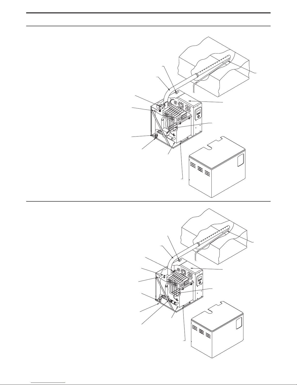
VAPORMIST® HUMIDIFIER OVERVIEW
Standard water models (VAPORMIST)
The standard water VAPORMIST unit requires
water conductivity of at least 100 µS/cm
(2 grains/gallon) to operate. It will not
operate with water treated
by reverse osmosis or
deionization processes
(see DI water model
below).
1½" (DN40) or 2" (DN50) flexible
vapor hose, pipe or tubing connects
to dispersion tube(s) or to an SDU
Water fill ¼" NPT (female)
Keyholes for
wall mounting
Water fill access hole
¾" NPT (DN20)
coupling, skimmer port
and overflow drain
Electrical conduit
knockouts
Removable
evaporating
chamber
Duct
Electrical area
INCOLOY alloy-sheathed
immersion heaters
Condensate
return line
Slide assembly under evaporating chamber
provides easy removal for cleaning
Deionized water models (VAPORMIST DI)
The VAPORMIST DI, shown here, is specifically
designed for use with deionized or reverse osmosis
water.
1½" (DN40) or 2" (DN50) flexible
vapor hose, pipe or tubing connects
to dispersion tube(s) or to an SDU
Float cutoff switch
Water fill ¼" NPT (female)
Keyholes for
wall mounting
Water fill access hole
¾" NPT (DN20) coupling,
skimmer port and overflow drain
Electrical
conduit
knockouts
OM-82-4
Duct
Electrical area
INCOLOY alloy-sheathed
immersion heaters
Condensate
return line
Removable
Ball valve
Slide assembly under
evaporating chamber provides
easy removal for cleaning
evaporating
chamber
OM-82-5
3
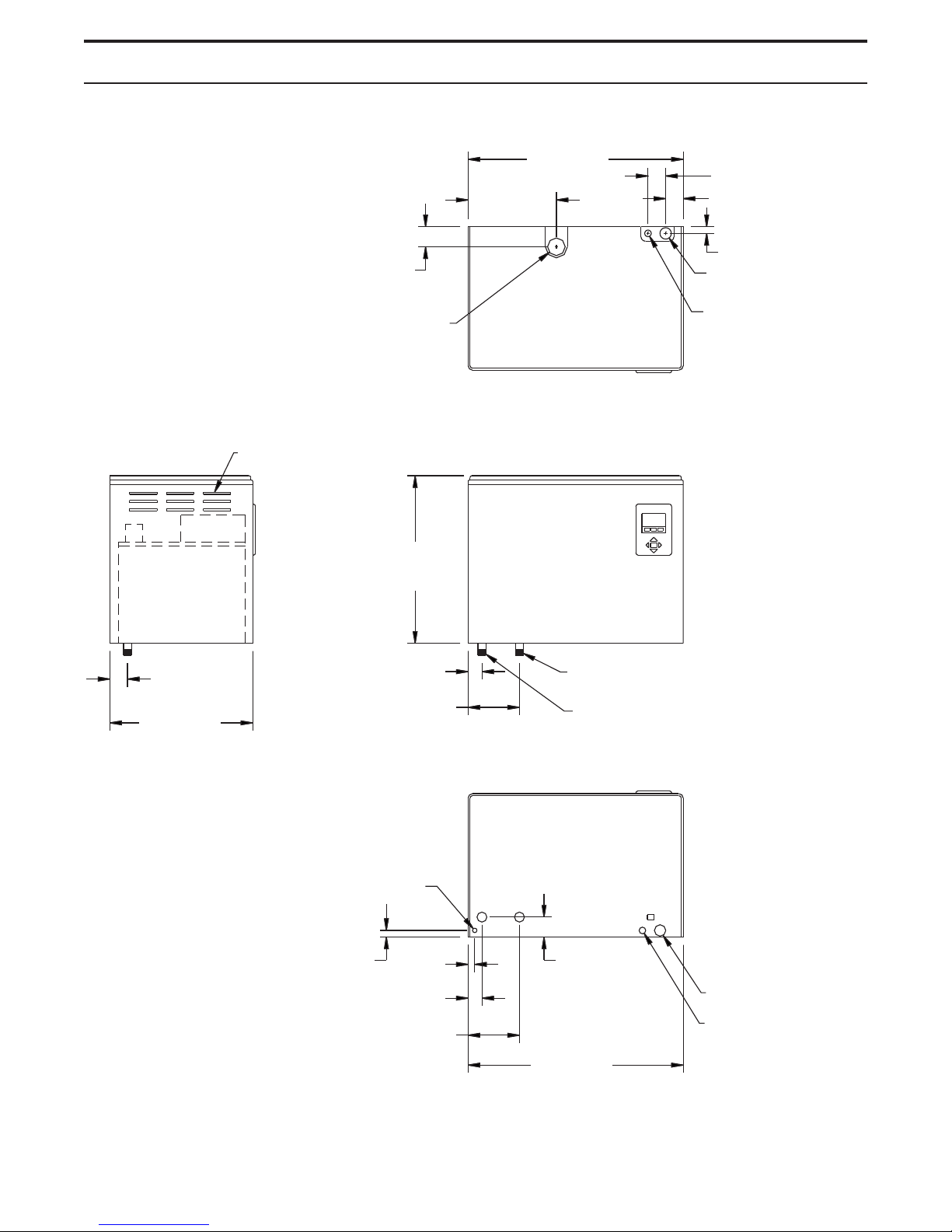
VAPORMIST® DIMENSIONS
Left side view
Venting
Top view
2.25" (57 mm)
Steam outlet
Front view
18.6"
(472 mm)
10.9"
(276 mm)
24.2"
(614 mm)
2" (50 mm)
2" (50 mm)
1" (25 mm)
Power wiring
knockout
Control or SDU
wiring knockout
2.25" (57 mm)
16.1"
(409 mm)
1.50" (38 mm)
5.75" (146 mm)
Bottom view
0.50" (13 mm) hole in
base for water fill line
0.75" (19 mm)
1.50" (38 mm)
5.75" (146 mm)
0.63"
(16 mm)
¾" NPT (DN20) frame drain
¾" NPT (DN20) tank drain
2.25" (57 mm)
Power wire
knockout
Control wiring
knockout
24.2"
(614 mm)
4
DC-1167
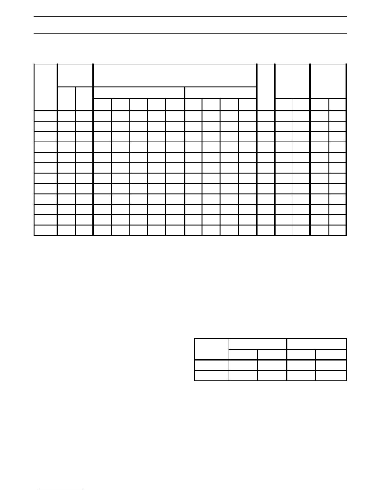
VAPORMIST specifications
VAPORMIST® SPECIFICATIONS
VM
model
number
2 6 2.7 16.7 9.6 8.3 4.2 3.3 -- -- -- -- 2 80 36 95 43
4 12 5.4 33.3 19.2 16.7 8.3 6.7 16.7** 14.4** 7.2** 5.8** 4 80 36 95 43
6 18 8.2 -- 28.8 25.0 12.5 10.0 25.0** 21.7** 10.8** 8.7** 6 88 40 122 55
8 24 10.9 -- 38.5 33.3 16.7 13.3 33.3** 28.9** 14.4** 11.5** 8 88 40 122 55
10 30 13.6 -- -- 41.7 20.8 16.7 29.1** 25.3** 12.6** 10.1** 10 93 42 139 63
12 36 16.3 -- -- -- 25.0 20.0 33.3 28.9 14.4 11.5 12 93 42 139 63
14 42 19.1 -- -- -- 29.2 23.3 38.9 33.7 16.8 13.5 14 93 42 139 63
16 48 21.8 -- -- -- 33.3 26.7 44.4 38.5 19.2 15.4 16 93 42 139 63
21 63 28.6 -- -- -- 43.8 35.0 -- -- 25.3 20.2 21 95 43 152 69
25 75 34.0 -- -- -- -- 41.7 -- -- 30.1 24.1 25 95 43 152 69
30 90 40.9 -- -- -- -- -- -- -- 36.1 28.9 30 101 46 156 71
34 102 46.3 -- -- -- -- -- -- -- 40.9 32.7 34 101 46 156 71
Steam
capacity
lbs/hr kg/h Single-phase Three-phase
120V 208V* 240V* 480
Table notes:
* On 208V/240V/single-phase/three-wire and on
208V/three-phase/four-wire supplies, the neutral
line provides a separate 120V circuit for the SDU
fan unit.
** For wire sizing, the highest leg draw is shown due
to current imbalance.
† Add the following to VAPORMIST weights if using
an SDU option:
Current draw (amps) kW Shipping
†
600V †208V* 240V †480V †600V
†
weight ‡
lbs kg lbs kg
Notes about SDUs (Space Distribution Units):
• The SDU-I is available for models VM-2 through VM-8,
and all VM-10 models except those using 240V, threephase power with SSR control.
• The SDU-E is available for all VAPORMIST models
except those models using 240V/480V/600V/threephase power with the SSR control option and
drawing more than 21.7 amps.
• SDUs ship separately from the VAPORMIST.
– SDU-I: 12 lbs (5.5 kg)
– SDU-E: 9 lbs (4 kg)
Note: These weights are for additional control
components housed within the VAPORMIST
cabinet. See the SDU weights table at right for SDU
weights (shipped separately).
‡ Add the following if using the SSR option:
– For single-phase or three-phase models drawing
SDU weights
SDU
model
SDU-I 68 31 58 26
SDU-E 61 28 51 23
Shipping weight Operating weight
lbs kg lbs kg
less than 21.7 amps, add 2 lbs (1 kg)
– For three-phase models drawing more than
21.7 amps, add 4 lbs (2 kg)
All VAPORMISTs operate at 50/60 Hz.
Operating
weight ‡
5
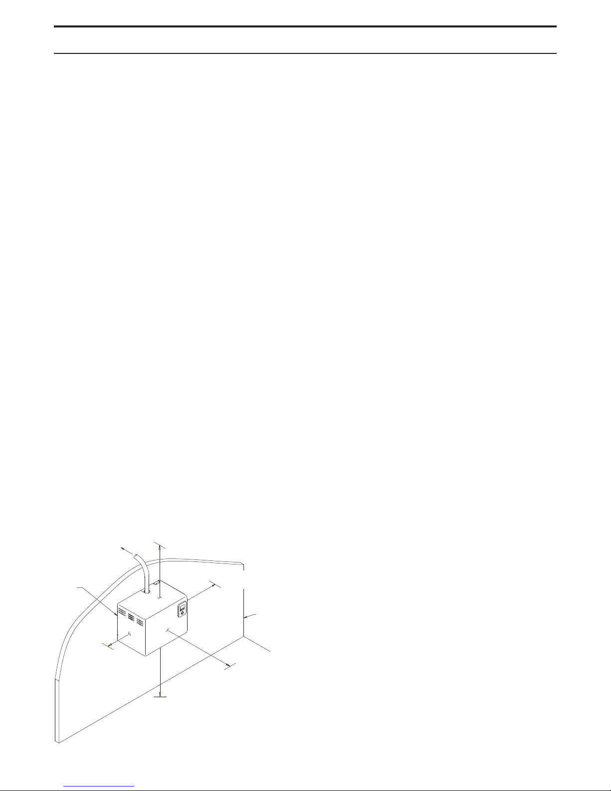
VAPORMIST® MOUNTING AND PIPING
Locating and mounting the humidifier
The VAPORMIST humidifier is designed to attach to
the wall with lag bolts, and it should be installed in a
space located near an air duct system, unless using a
Space Distribution Unit (SDU) for dispersion.
Consider the following when selecting the location of
the humidifier:
• Convenient access to duct
• Electrical and plumbing connections
• Required clearances
• External water seal requirements
Electrical power supply, water makeup piping and drain
piping must also be considered. Electrical power
supply connections are made at the lower or upper
right rear corner of the unit. Water makeup and drain
piping connections are made at the lower left rear
corner.
When mounting on a stud wall (studs 16" [406 mm] on
center), locate studs and position lag bolts in place so
that each of the bolts will center on a stud. Mark hole
locations and predrill ¼" (6 mm) diameter pilot holes
using mounting template on the VAPORMIST box.
Secure frame to wall with lag bolts provided.
VAPORMIST piping
Water makeup piping may be of any code-approved
material (copper, steel, or plastic). The final connection
size is ¼" NPT (DN8). In cases where water hammer
may be a possibility, a shock arrestor should be
considered. Water pressure must be between 25 psi
and 80 psi (175 kPa and 550 kPa).
Drain piping may be of any code-approved material
(copper, steel, or plastic rated for 212 °F [100 °C]
minimum). If drainage by gravity is not possible, use a
small pump (DRI-STEEM Part No. 400280).
The final connection size is ¾" NPT (DN20) for tank
and frame drains. This connection size should not be
reduced. (See the drawings on the following pages for
proper drain piping configurations.) The tank drain
should be piped separately from the frame drain, as
shown, to prevent backflow of drain water into the
humidifier cabinet.
Install a union in the water supply line as shown in
the drawings on the next two pages to allow tank
removal.
For hollow block or poured concrete wall mounting,
position template in place and mark the holes. Drill
appropriate pilot holes for two 3/8" (10 mm) toggle
bolts or two 3/8" (10 mm) machine bolt lead anchors.
Secure frame in place.
Clearance recommendations
For recommended service and maintenance purposes,
maintain the following clearances:
Top (when SDU is not
mounted directly above the
To dispersion
unit
Secured to
supporting
wall
Left side:
12" (305 mm)
VAPORMIST): 18" (460 mm)
Right side electrical
controls: 36" (915 mm)
Supporting
wall
Front: 36" (915 mm)
Floor: 24" (610 mm)
6
DC-1201
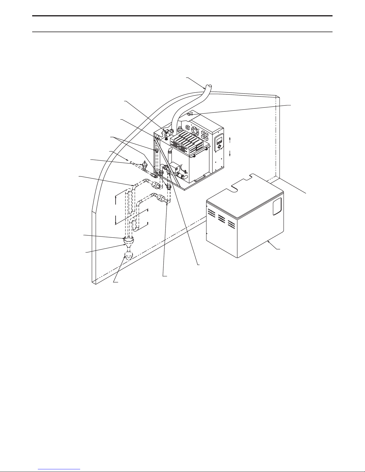
VAPORMIST® PIPING
VAPORMIST (standard water) field piping overview
Steam vapor hose
¼" NPT (DN8) connection to water
supply line; water pressure must be
between 25 psi and 80 psi (175 kPa
and 550 kPa); water conductivity
minimum 2 grains/gallon (100 µS/cm)
Two keyholes for wall
mounting, 16" (406 mm)
on center
Unions by installer
Water supply line
Shock arrester
recommended to
reduce water hammer
¾" NPT (DN20) tank
drain, skimmer and
P-trap piping, rated
for 212 °F (100 °C).
If piping run is over
10' (3 m) increase
pipe to 1¼" (DN32)
after P-trap.
12"
(300 mm)
(maximum run 10' [3 m]).
May also use pipe or
tubing.
2" (50 mm)
Install plumb
Electrical conduit
knockouts provided
top and bottom:
• Combination, for
½" and ¾"conduit
connectors (knockout diameters
22.3 mm and
28.6 mm)
• Combination, for
¾" and 1" conduit
connectors (knockout diameters
28.6 mm and
34.9 mm)
1" (25 mm) air gap
Spill funnel.
Plumb to
floor drain
Open floor drain.
Refer to local codes
for drain pipe size
and maximum
temperature
requirements.
Frame drain
¾" NPT (DN20)
frame drain and
P-trap piping, rated
for 212 °F (100 °C)
Cover
Notes:
• Offset humidifier from spill funnel or floor drain to prevent flash steam from rising into the cabinet.
• Dashed lines indicate provided by installer.
• The water supply inlet is more than 1" (25 mm) above the skim/overflow port, eliminating the possibility
of backflow or siphoning from the tank. No additional backflow prevention is required, however, local
codes prevail.
• Install a union in the water supply line as shown to allow tank removal.
DC-1136
7
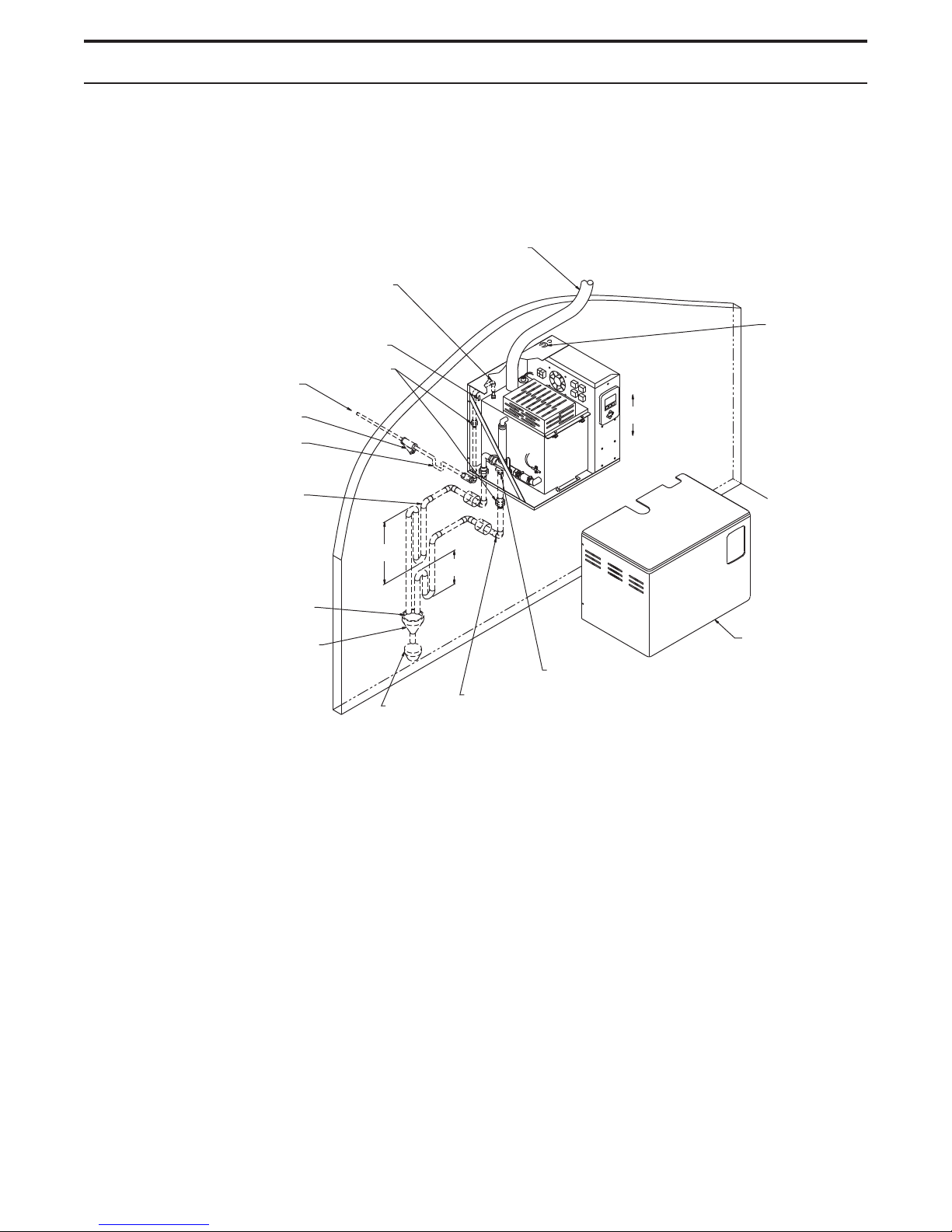
VAPORMIST® PIPING
VAPORMIST DI (deionized/reverse osmosis water) field piping overview
¼" NPT (DN8) connection to water
supply line; water pressure must be
between 25 psi and 80 psi (175 kPa
and 550 kPa); water chloride content
must be less than 3 ppm; first
3' (1 m) of supply line must be
rated for 212 °F (100 °C)
Two keyholes for
wall mounting, 16"
(406 mm) on center
Water supply line
Strainer,
by installer
If water piping to humidifier is non-metallic,
we recommend a 2" (50 mm) water seal in
the supply line to isolate steam during
DI/RO water system maintenance
¾" NPT (DN20) tank drain and P-trap
piping, rated for 212 °F (100 °C);
if piping run is over 10' (3 m)
increase pipe to 1¼" (DN32)
after P-trap
1" (25 mm) air gap
Spill funnel.
Plumb to
floor drain
Unions by
installer
12"
(300 mm)
Open floor
drain. Refer
to local codes for drain
pipe size and maximum
temperature requirements.
Steam vapor hose
(maximum run 10'
[3 m]). May also use
pipe or tubing
2" (50 mm)
¾" NPT (DN20)
frame drain and
P-trap piping, rated for
212 °F (100 °C)
Frame drain
Install plumb
Electrical conduit
knockouts provided
top and bottom:
• Combination, for
½" and ¾"conduit
connectors (knockout diameters
22.3 mm and
28.6 mm)
• Combination, for
¾" and 1" conduit
connectors (knockout diameters
28.6 mm and
34.9 mm)
Cover
DC-1139
Notes:
• Offset humidifier from spill funnel or floor drain to prevent flash steam from rising into the cabinet.
• Dashed lines indicate provided by installer.
• The water supply inlet is more than 1" (25 mm) above the overflow port, eliminating the possibility of backflow
or siphoning from the tank. No additional backflow prevention is required, however, local codes prevail.
• Install a union in the water supply line as shown to allow tank removal.
8
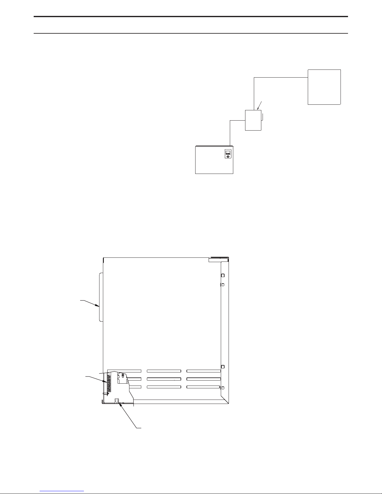
VAPORMIST®WIRING
VAPORMIST wiring
All wiring must be in accordance with all governing
codes, and with the VAPORMIST or VAPORMIST DI
wiring diagram. The diagrams are located inside the
removable subpanel cover on the right side of the
humidifier cabinet. Power supply wiring must be rated
for 105 °C.
When selecting a location for installing the
VAPORMIST, avoid areas close to sources of
electromagnetic emissions such as power distribution
transformers.
The use of semiconductor fusing sized per the National
Electric Code is recommended with the SSR option.
Grounding requirements
The earth must be made by solid metal to metal
connections. The ground must be a good radio
frequency earth. Ground wire should be same size as
power wiring.
Shielded/screened cable drain wire connection to lug
Field wiring requirements
Power supply
Fused disconnect
(provided by
installer)
(provided by
installer)
OM-1007
Note: Control wiring and power wiring must be run in
dedicated or separate earthed metal conduit, cable
trays or trunking.
VAPOR-LOGIC
keypad on front of
cabinet
Microprocessor
board
3
Right side view of VAPORMIST
OM-1505
Shield/screen ground lug
Note: For maximum EMC effectiveness, all humidity, temperature, and airflow controls should be wired using
multicolored shielded/screened plenum-rated cable with a drain wire for the shield/screen. The drain wire should
be connected to the shield/screen ground terminal with its length kept to less than 2".
9
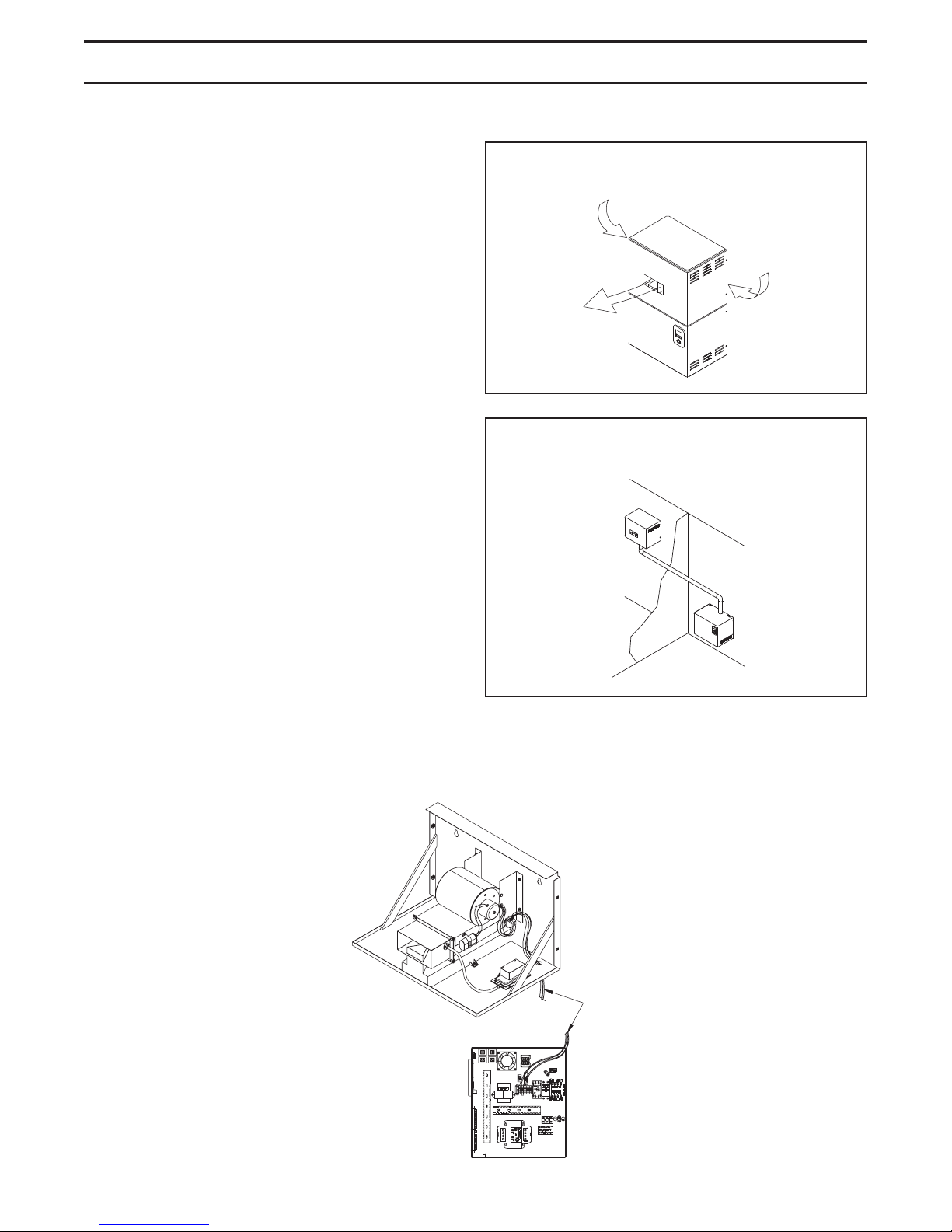
VAPORMIST® DISPERSION
SDU-I:
Provides instant, internal absorption
The Space Distribution Unit Internal Absorption
(SDU-I) disperses humidity with no visible vapor trail
or wetness, making the VAPORMIST® with an SDU-I
ideal for use in finished spaces. When room RH is 45%
or less, the SDU-I fan mixes room air and steam to
ensure complete absorption before discharge as
humidified air. The SDU-I is available for models VM-2
through VM-8, and all VM-10 models except those
using 240 V, three-phase power with SSR control.
SDU-E:
For higher capacity units
The Space Distribution Unit External Absorption
(SDU-E) is designed for higher capacity dispersion.
The SDU-E is available for all VAPORMIST models
except those models using 240V/480V/600V/threephase power with the SSR control option and drawing
more than 21.7 amps.
Mounting the SDU-I and SDU-E
Both SDUs may be mounted on a wall directly above
the VAPORMIST cabinet or mounted on a wall remote
from the VAPORMIST. Use the mounting template on
the box for correct placement. Two lag bolts are
provided with each fan unit.
The SDU can be mounted directly
above the VAPORMIST.
Air
intake
vents
Steam
outlet
OM-55-1
The SDU can be mounted remotely
from the VAPORMIST.
Note: See the following pages for more information
about SDU-I and SDU-E.
SDU field wiring
OM-56-1
SDU-E
Field wiring for
fan and airflow
proving switch
VAPORMIST
Electrical panel
right side view
10
OM-921
 Loading...