

DriSteem Vapor-logic 3, Vapor-logic 6, Vapormist, Humidi-tech Field Conversion Instructions
Page 1
Vapor-logic® verision 3 to Vapor-logic version 6 Field
Conversion Instructions: Vapormist
®
and Humidi-tech®
Humidifi ers
1. Note the board orientations shown in Figure 3-1. The photos depict
the orientation of the Vapor-logic version 3 board before removal, and the
recommended Vapor-logic version 6 board orientation.
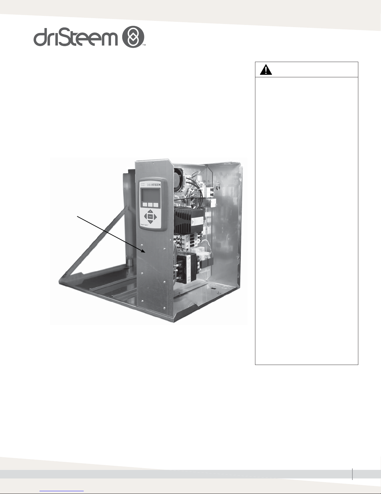
2. Remove the six screws holding the Vapor-logic version 3 board to the
front panel (see photo below). This will allow for board movement during
terminal removal.
Vapor-logic version 3 board
is mounted to the back
of this panel.
3. Leave the wires connected to the Vapor-logic version 3 board terminals.
Use needlenose pliers to pull the terminals off of the pins.
Note: The Vapor-logic version 6 board has adhesive-backed standoffs that
adhere to the subpanel. For best adhesion, make sure the subpanel
surface is clean and dry.
4. Remove the adhesive backing paper from the standoffs, and press the
Vapor-logic version 6 board onto the subpanel as close as possible to the
original footprint of the Vapor-logic version 3 board.
5. See Figure 3-1. The Vapor-logic version 3 disconnections and
Vapor-logic version 6 connections needed for this conversion are labeled.
Note: If any wires are too short to reach their new locations on the
Vapor-logic version 6 board, add pigtail extensions to them.
WARNING
Fire and electrical shock hazards
This page provides important
safety instructions; it is intended to
supplement — not replace — the
humidifi er's Installation, Operation,
and Maintenance Manual (IOM). Read
the IOM that was provided with the
humidifi er before performing service
or maintenance procedures on any
part of the system. Failure to follow
all warnings and instructions could
produce the hazardous situations
described here and in the IOM,
resulting in property damage, personal
injury, or death.
If the IOM is missing, go to
www.dristeem.com to download a
replacement.
Improper installation, adjustment,
alteration, service, maintenance, or
use can cause fi re, electrical shock,
and other hazardous conditions. These
hazardous conditions could cause
personal injury, property damage, or
death.
To prevent hazardous conditions, read
all warnings; lock all power disconnect
switches in the OFF position before
removing any access panels; and
consult a qualifi ed installer, service
agency, or your distributor or branch
for information or assistance. The
qualifi ed installer or agency must use
only factory authorized and listed kits
or accessories when modifying this
product.
Note: If literature shipped with the humidifi er
is not available, historical literature is
available at www.dristeem.com.
DriSteem® humidifi ers are warranted according
to the terms and conditions of the standard
two-year Limited Warranty effective when the
humidifi er was purchased. See the literature
that was shipped with the humidifi er for
warranty information.
mc_081308_1405
VAPOR-LOGIC 3 TO VAPOR-LOGIC 6 FIELD CONVERSION INSTRUCTIONS: VAPORMIST AND HUMIDI-TECH HUMIDIFIERS
1
Page 2
6. Skip this step if the humidifier does not have the SSR option (see photo at right):
Disconnect wire #434 from Vapor-logic version 3 terminal 34, and connect it to Vapor-logic
version 6 P19 terminal +SSR. Disconnect wire #435 from Vapor-logic version 3 terminal 35,
and connect it to Vapor-logic version 6 P19 terminal –BL.
7. Disconnect the wires from Vapor-logic version 3 terminals 1, 3, and 5, and connect them
to the following Vapor-logic version 6 P17 terminals: Connect wire #401 to FILL, #403 to
DRAIN, and #405 CT1.
8. Disconnect wires #402, #404, #406, and #408 from Vapor-logic version 3 terminals 2, 4, 6,
and 8. Tie them together with a wire nut and pigtail them to a single common that goes to a
DIN rail terminal C.
There are no dedicated common terminals on the Vapor-logic version 6 board. That is why, in
this step, the Vapor-logic version 3 commons get tied together with a wire nut. See the gray
text box in Figure 3-1.
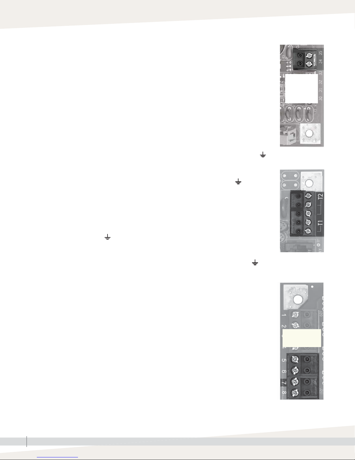
Lower-right corner of
Vapor-logic version 3
board
No SSR option
if no wires
connected to
terminals 34
and 35
9. Disconnect the wires from Vapor-logic version 3 terminals 19 and 20, and connect them to
the following Vapor-logic version 6 P4 terminals: Connect wire #419 to TT, and #420 to .
10. Disconnect wires #802 and #000 from Vapor-logic version 3 terminals T1 and T2. If
the terminals are not marked, see the photo at right. Connect the wires to the following
Vapor-logic version 6 P1 terminals: Connect wire #802 to 24VAC and #000 to .
11. Connect a new wire to 24VAC (where wire #802 is already connected). Connect the new
wire to P3 terminal LW and P4 terminal Isw.
12. Humidifi er with tap/softened water:
Disconnect the wires from Vapor-logic version 3 terminals 30, 31, 32, 33, and connect them
to the following Vapor-logic version 6 P2 terminals: Connect wire #430 to TOP, #431 to MID,
#432 to LOW, and #433 to .
Humidifier with the DI water option:
Disconnect the wires from Vapor-logic version 3 terminals 32 and 33, and connect them to the
following Vapor-logic version 6 P2 terminals: Connect wire #432 to LOW and #433 to .
13. Skip this step if the humidifier does not have the SDU option (see bottom photo on this page):
• Disconnect wire #407 from Vapor-logic version 3 terminal 7, and connect it to Vapor-logic
version 6 P16 terminal SDU.
• Disconnect wire #810 from relay terminal 24, cut off the connector, strip the end of the
wire, and connect it (with wire #407) to Vapor-logic version 6 P16 terminal SDU.
• Connect SDU fan wire #000 on the subpanel to common wires #402, #404, #406, and
#408 that were tied together in step 8.
14. Remove the four keypad/display mounting screws (save the screws), and remove and
disconnect the Vapor-logic version 3 keypad/display.
Upper-right corner of
Vapor-logic version 3
board
Upper-left corner of
Vapor-logic version
3 board
No SDU option If
no wire connected
to terminal 7
15. The kit was shipped with a Vapor-logic version 6 keypad/display. Plug one end of the
existing display cable into the Vapor-logic version 6 board DISPLAY connection (shown in
Figure 3-1), and plug the other end into the Vapor-logic version 6 keypad/display.
16. Install the Vapor-logic version 6 keypad/display using the screws from step 14.
17. External connections: Refer to the Vapor-logic version 3 wiring diagram and the
Vapor-logic version 6 external connection requirements in the VL-1 wiring diagram shipped
with the conversion kit.
VAPOR-LOGIC 3 TO VAPOR-LOGIC 6 FIELD CONVERSION INSTRUCTIONS: VAPORMIST AND HUMIDI-TECH HUMIDIFIERS
2
Page 3

FIGURE 3-1: VAPOR-LOGIC VERSION 3 BOARD DISCONNECTIONS AND VAPOR-LOGIC VERSION 6 BOARD CONNECTIONS
430
431432
433
434
408
406
404
402
401
403
405
407
Control
terminals
419
420
Control
terminals
Commons to wire nut. See note at right.
1
2
3
4
5
6
7
8
Vapor-logic 3 board
disconnections
19
20
Wire nut
Multiple commons from Vapor-logic 6
board. Vapor-logic 6 board does not
have common (c) terminals.
T2
000
T1
802
Display connection
Typical Vapor-logic boards shown
Connections for SSR option.
See step 6 on Page 2.
435
35
34
434
433
33
432
32
31
431
30
430
408
406
404
402
000 from SDU fan wire on subpanel.
See step 13 on Page 2.
t
Network connection
Probe connections for tap/softened water.
Low water switch connections for DI water option.
See step 12 on Page 2.
Field-connected control terminals
810 from relay terminal 24 for SDU option.
See step 13 on Page 2.
407
401
403
405
434
435
SDU
FILL
DRAIN
CT1
+SSR
– BL
P16
P17
P18
P19
Vapor-logic 6
board connections
P4
P3
P2
P1
TT
lsw
LW
TOP
MID
L
OW
24VAC
420
419
433
430
431
432
000
802
VAPOR-LOGIC 3 TO VAPOR-LOGIC 6 FIELD CONVERSION INSTRUCTIONS: VAPORMIST AND HUMIDI-TECH HUMIDIFIERS
3
Page 4

Expect quality from the industry leader
Since 1965, DriSteem has led the industry with
innovative methods for humidifying and cooling
air with precise control. Our focus on ease
of ownership is evident in the design of the
Vapor-logic controller. DriSteem also leads the
industry with a Two-year Limited Warranty and
optional extended warranty.
For more information
www.dristeem.com
sales@dristeem.com
For the most recent product information
visit our website: www.dristeem.com
DRI-STEEM Corporation
a subsidiary of Research Products Corporation
DriSteem is an ISO 9001:2000 certifi ed company
U.S. Headquarters:
14949 Technology Drive
Eden Prairie, MN 55344
800-328-4447 or 952-949-2415
952-229-3200 (fax)
European offi ce:
Grote Hellekensstraat 54 b
B-3520 Zonhoven
Belgium
+3211823595
E-mail: dristeem-europe@dristeem.com
Continuous product improvement is a policy of
DriSteem; therefore, product features and
specifi cations are subject to change without
notice.
DriSteem, Humidi-tech, Vapor-logic, and
Vapormist are registered trademarks of
Research Products Corporation and are fi led
for trademark registration in Canada and the
European community.
Product and corporate names used in this
document may be trademarks or registered
trademarks. They are used for explanation only
without intent to infringe.
© 2016 Research Products Corporation
Form No. VL3-to-VL6-Vapormist-Humidi-tech-0316
Part No. 890000-753 Rev. A
 Loading...