

DriSteem Ultra-sorb LV, Ultra-sorb LH Installation, Operation And Maintenance Manual
Ultra-sorb
Steam Dispersion Tube
Humidifier Panel
®
Installation, Operation,
and Maintenance Manual
For applications using steam from
a boiler or from any DRI-STEEM
steam generating humidifier.

Table of contents
Overview
Unpacking High-eciency tubes ...........................3
Field assembly of Model LH ...............................4
Field assembly of Model LV ...............................7
Installation
Selecting the location ...................................... 10
Determine humidier placement ............................11
Installation in a cold air stream .............................12
Mounting in a horizontal duct ..............................13
Mounting in a vertical duct ................................14
Installation inside an air handling unit .......................15
Supply and drain connections and dimensions ................16
Piping ................................................... 17
Mounting ...............................................19
Retrofitting an existing Ultra-sorb ..........................20
Performance data .........................................22
Maintenance
Maintenance .............................................23
Troubleshooting guide .....................................24
Replacement parts ........................................26
Warranty .........................................Back cover
Page 2 • DRI-STEEM Ultra-sorb Steam Dispersion Panel Installation, Operation, and Maintenance Manual

Unpacking High-efficiency tubes
NOTE: If you have an Ultra-sorb without High-efficiency
dispersion tubes (non-insulated tubes), please skip to the next
page.
Unpacking
• Remove the dispersion assembly from the shipping container; be
careful not to bump or scrape the PVDF insulating material on
the dispersion tubes.
• Some dispersion panels are shipped unassembled by customer
request or by shipping necessity. Do not lay High-efficiency tubes
across or under anything that could compress or damage the
insulating material. Compressed insulating material has a reduced
R-value.
• Avoid bumping or snagging the PVDF insulating material.
Although PVDF is robust, rough handling can cause tears, which
could negatively impact performance.
•
Before start-up, remove the clear poly film by tearing it along the
perforation.
Do not use a knife or sharp object to remove the poly
film.
CAUTION!
The High-efficiency tubes are sleeved in clear poly
film for protection during processing, shipping,
and installation.
To prevent dirty insulating material, leave the clear
poly film on until installation is complete.
Equally important, remove and discard the clear
poly film before start-up by tearing it along the
perforations.
Figure 3-1:
Ultra-sorb with the High-efficiency
Tube option
High-efficiency Tube option
Ultra-sorb dispersion assemblies with the
High-efficiency Tube option are designed to
produce significantly less dispersion-generated
condensate and airstream heat gain, which
reduces wasted energy by up to 85%. These
improvements are accomplished by reducing
the thermal conductivity of the tubes with
1/8" of polyvinylidene fluoride (PVDF)
insulating material on the outside of the tubes.
These assemblies require careful unpacking,
installation, and handling. If your dispersion
assembly has the High-efficiency Tube option,
be sure to read this section carefully.
DRI-STEEM Ultra-sorb Steam Dispersion Panel Installation, Operation, and Maintenance Manual • Page 3
Field assembly of Model LH
Table 4-1:
Ultra-sorb Model LH components
Description Qty.
Supply header assembly with shouldered
slip couplings
Condensate header assembly 1
Mounting flange 2
Dispersion tubes with slip couplings varies
¼ - 20 x ¾" bolt 8
¼ - 20 nut 8
¼ lock washer 8
1
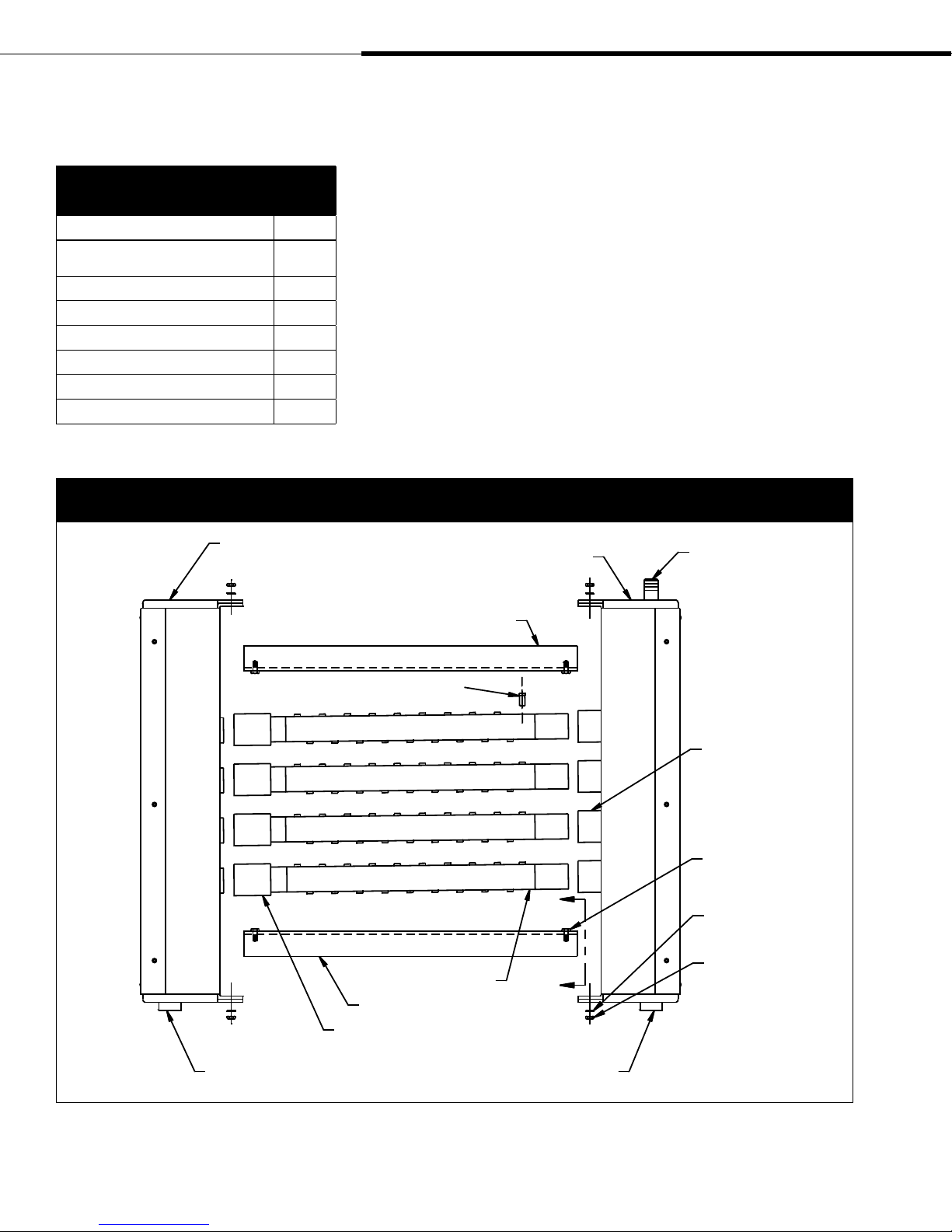
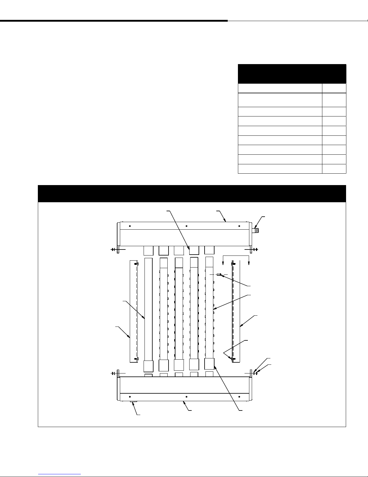
Figure 4-1:
Ultra-sorb Model LH
Condensate header assembly
Please read instructions while assembling
STEP 1 - Unpack
Unpack the Ultra-sorb components and verify that you have all
items on the packing list.
Note that both the supply header assembly and the condensate
header assembly have a ¾" half coupling drain connection on one
end. This will be the lower end of the installed dispersion assembly.
The supply header assembly has a steam inlet (nipple or tubing) on
the end opposite the drain connection.
Arrange the components on a large, flat working surface,
positioning them as indicated in Figure 4-1 (condensate header to
the left, supply header to the right).
Supply header assembly
Mounting flange
Steam inlet
¾" pipe thread coupling
(DN 20) drain connection
Tubelet
Dispersion tube
Mounting flange
Slip coupling without shoulder
¾" pipe thread coupling
(DN 20) drain connection
Slip coupling
with shoulder
¼" - 20 nut (8)
Washer (8)
¼" - 20 nut (8)
OM-238-1
Page 4 • DRI-STEEM Ultra-sorb Steam Dispersion Panel Installation, Operation, and Maintenance Manual
Field assembly of Model LH
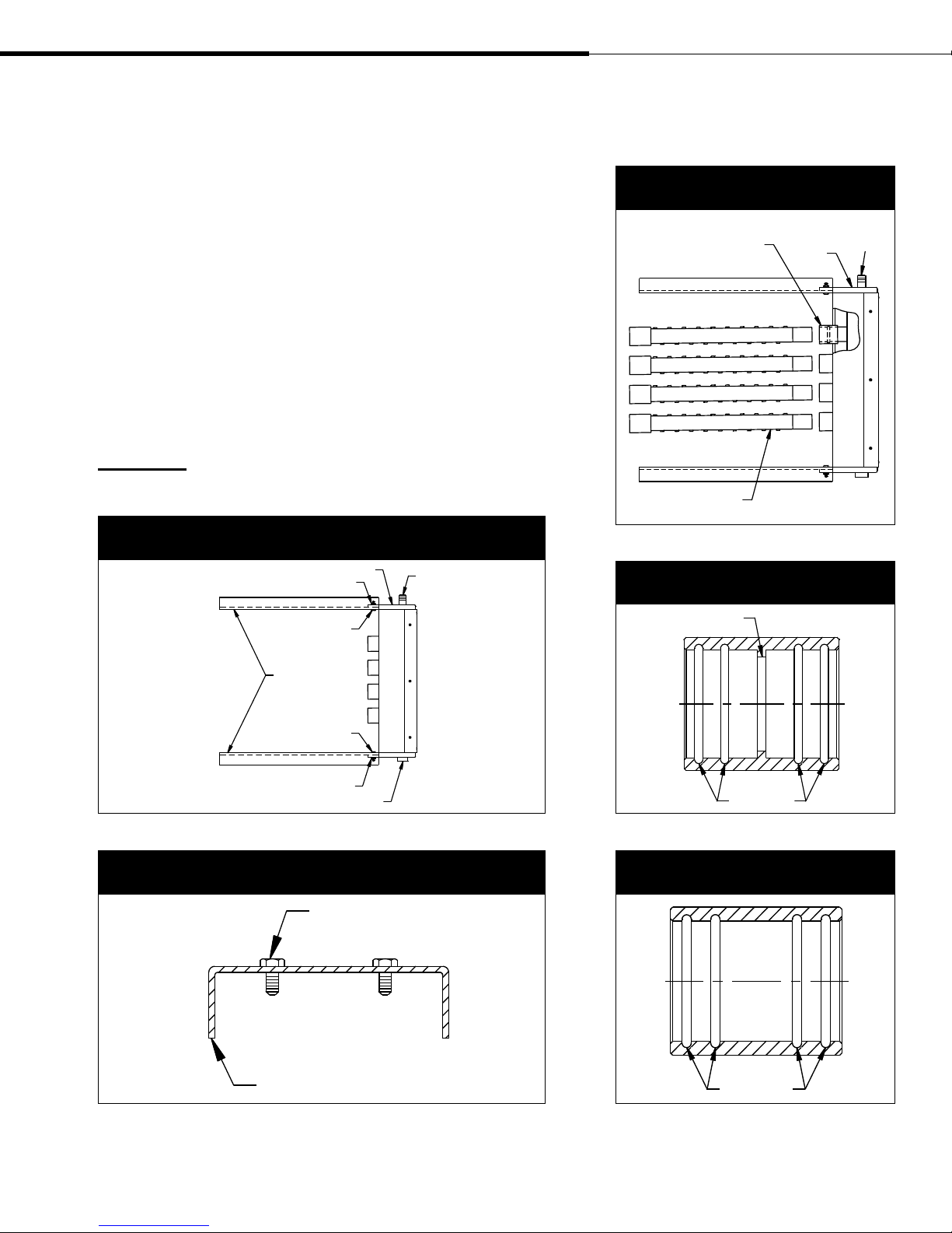
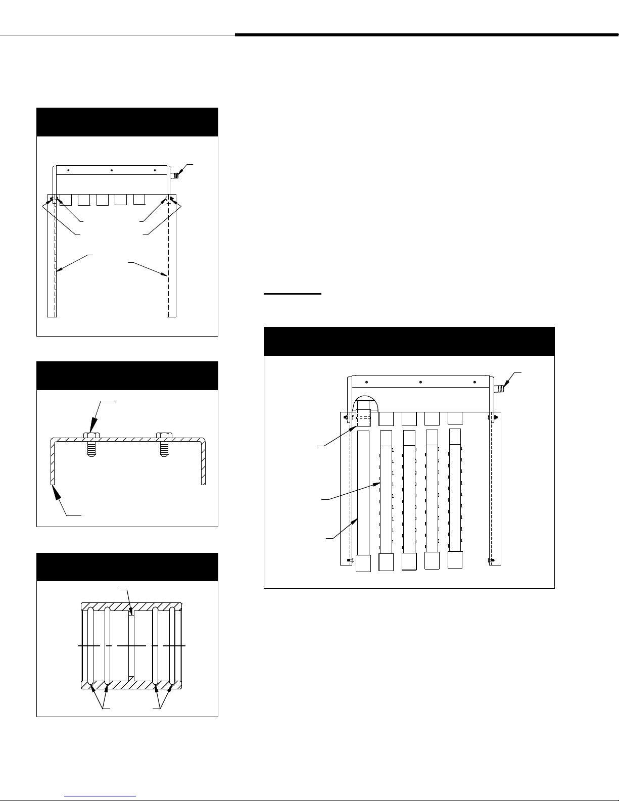
STEP 2 - Bolt the mounting flanges to the supply header
assembly
Refer to Figure 5-1 and 5-2.
Attach the two mounting flanges to the supply header assembly as
indicated using ¼" - 20 bolts with the nuts finger tight.
STEP 3 - Insert the dispersion tubes
Refer to Figure 5-3. Insert the plain ends (no slip couplings)
of the dispersion tubes into the slip couplings already mounted
on the supply header assembly. The slip couplings are factory
lubricated; if well aligned during insertion, no further lubrication
should be needed. Push and twist the tube in until it bottoms out
on the internal shoulder of the slip coupling (see Figure 5-4).
CAUTION! Use care to avoid cutting the internal O-rings of the
slip couplings.
Figure 5-1:
Supply header assembly
Supply header assembly
Washer and nut
¼" - 20 bolt
Steam inlet
Figure 5-3:
Dispersion tubes
Slip coupling with shoulder
Dispersion tube
Supply header
assembly
Figure 5-4:
Slip coupling with shoulder
Shoulder
Steam
inlet
OM-238-3
Mounting flange
¼" - 20 bolt
Washer and nut
Drain connection
Figure 5-2:
Detail view of mounting flange
Mounting flange
¼" - 20 bolts
OM-238-2
OM-239
O-rings
Figure 5-5:
Slip coupling without shoulder
O-rings
OM-238-6
OM-238-7
DRI-STEEM Ultra-sorb Steam Dispersion Panel Installation, Operation, and Maintenance Manual • Page 5
Field assembly of Model LH
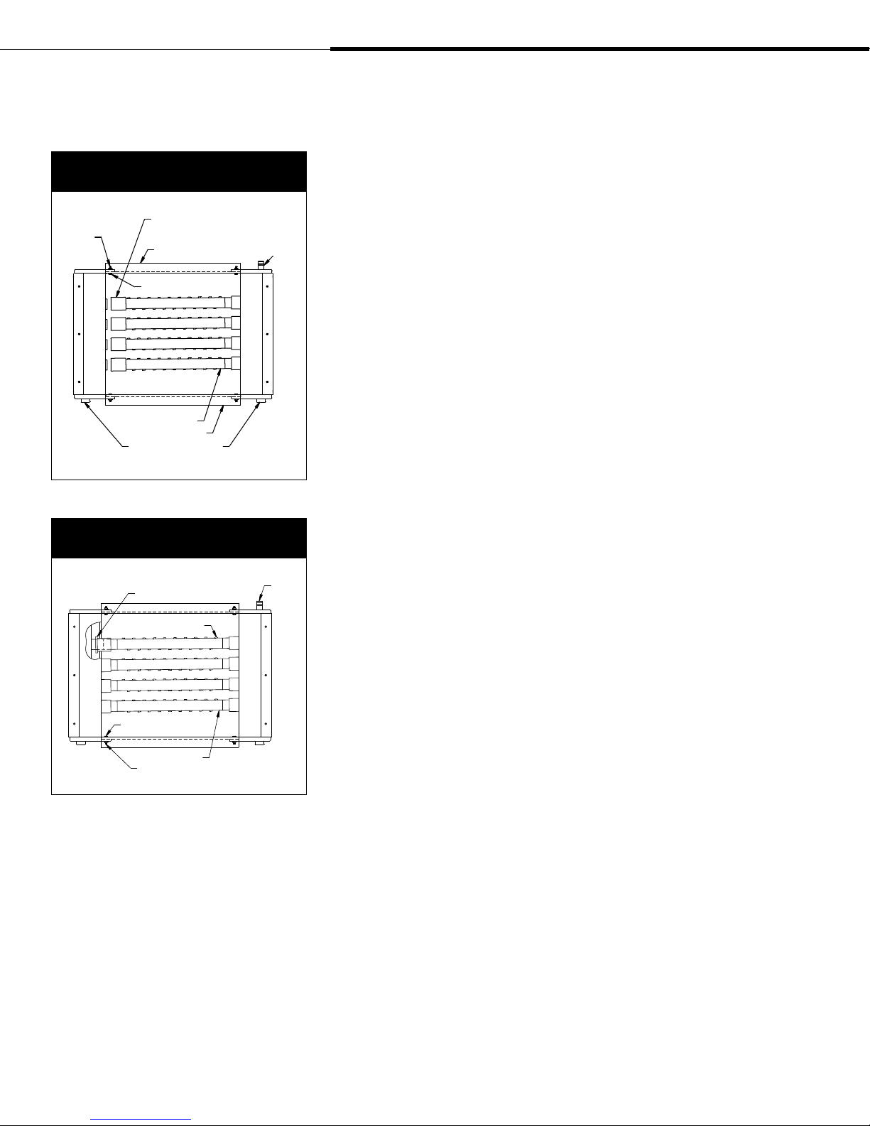
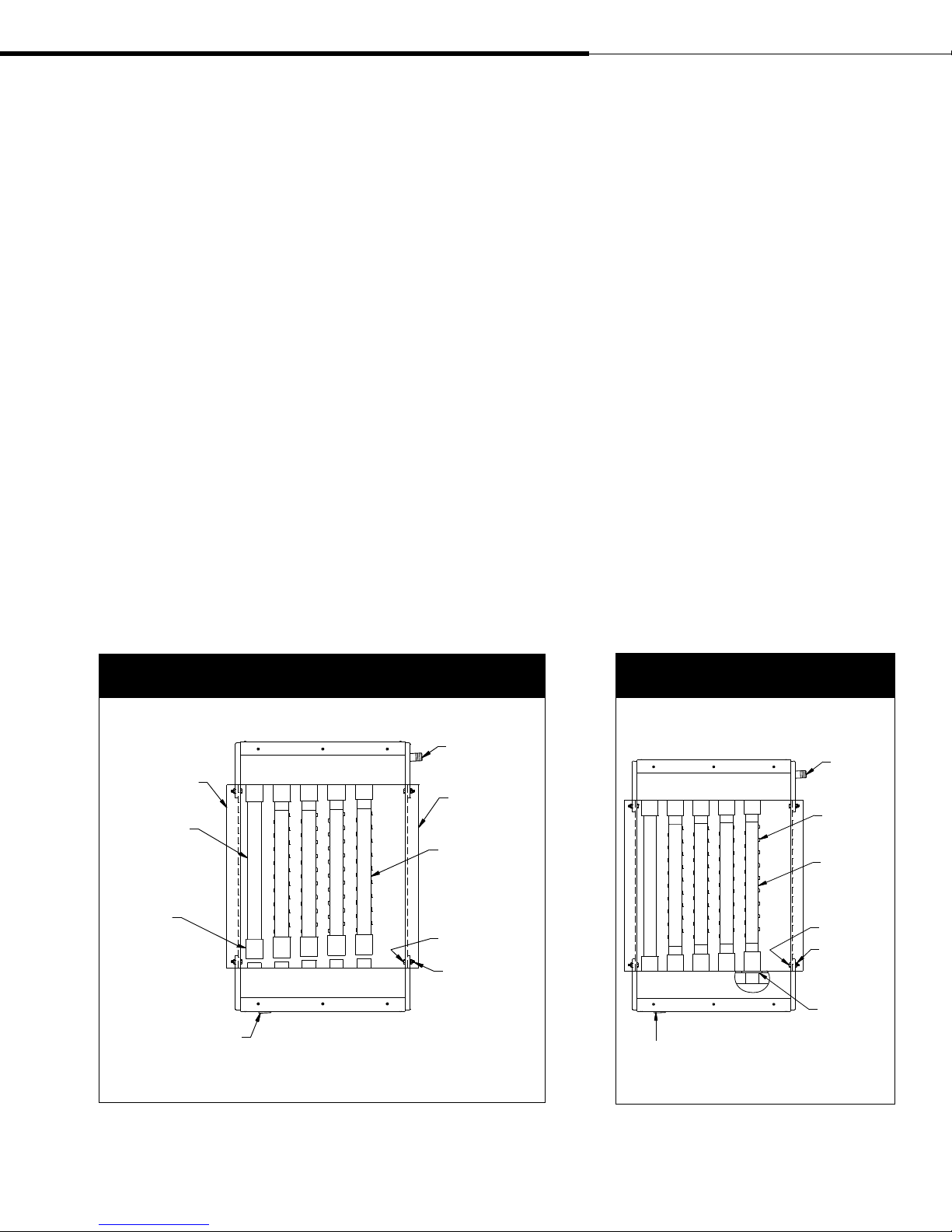
Figure 6-1:
Condensate header assembly
Align coupling (without shoulder)
Washer
and nut
Condensate header assembly
flush with end of dispersion tube
Mounting flange
¼" - 20 bolt
Dispersion tube
Mounting flange
Drain connection
Figure 6-2:
Slip coupling placement
Stop disc
Steam
inlet
Supply header assembly
OM-238-4
Steam
inlet
STEP 4 - Bolt the mounting flanges to the condensate header
assembly
Refer to Figure 6-1. Push the slip couplings onto the dispersion
tubes flush with the tube ends. Make sure the drain connection is
properly oriented. Attach the mounting flanges using
¼" - 20 bolts,
and leave the nuts finger tight.
STEP 5 - Slide the slip couplings onto the condensate header assembly and orient the tubelets
SUGGESTION: Gripping the drain connection with vise grip pliers
and applying a back and forth rolling motion to the header will
assist in sliding the slip couplings into place.
Refer to Figure 6-2. It may be necessary to push and twist the
slip couplings onto the condensate header. Again care must be
taken to avoid cutting the internal O-rings. Slide the slip couplings
on until they bottom out against the stop disc on the condensate
header. The steam tubelets must be aimed so that they discharge the
steam perpendicular to the airstream. Rotate the dispersion tubes as
needed.
After tightening the ¼" - 20 bolts at all 4 corners, the Ultra-sorb
panel is ready for installation. See page 10.
Tubelet
Condensate header assembly
¼" - 20 bolt (8)
Dispersion tube
Nut and washer (8)
Supply header assembly
OM-238-5
Page 6 • DRI-STEEM Ultra-sorb Steam Dispersion Panel Installation, Operation, and Maintenance Manual
Field assembly of Model LV
Please read instructions while assembling
STEP 1 - Unpack
Unpack the Ultra-sorb components and verify that you have all
items on the packing list.
Lay the components on a flat surface, and position the header
assemblies as shown in Figure 7-1. Orient the condensate header
assembly so the ¾" half coupling drain connection is to your left,
and orient the supply header assembly so the steam inlet (nipple or
tubing) is to your right.
Figure 7-1:
Ultra-sorb Model LV
Slip coupling
with shoulder
Supply header
assembly
Table 7-1:
Ultra-sorb Model LV components
Description Qty.
Supply header assembly with shouldered
slip couplings
Condensate header assembly 1
Mounting flange 2
Dispersion tubes with slip couplings varies
Condensate drain tube 1
¼ - 20 x ¾" bolt 8
¼ - 20 nut 8
¼ lock washer 8
Steam inlet
1
Condensate drain
Mounting flange
¾" pipe thread coupling
(DN 20) drain connection
A
Condensate header
assembly
A
Tubelet
Dispersion tube
Mounting flange
¼" - 20 bolt (8)
Washer (8)
¼" - 20 nut (8)
Slip coupling without shoulder
OM-260-1
DRI-STEEM Ultra-sorb Steam Dispersion Panel Installation, Operation, and Maintenance Manual • Page 7
Field assembly of Model LV
Figure 8-1:
Supply header assembly
Supply header assembly
¼" - 20 bolt
Washer and nut
Mounting
flange
Figure 8-2:
Detail view of mounting flange
¼" - 20 bolts
Steam
inlet
OM-260-2
STEP 2 - Bolt the mounting flanges to the supply header
assembly
Refer to Figure 8-1 and 8-2. Attach the two mounting flanges
as indicated using ¼" - 20 bolts with the nuts only finger tightened.
STEP 3 - Insert the dispersion tubes
Refer to Figure 8-4. Insert the plain ends (no slip couplings) of
the dispersion tubes into the slip coupling already mounted on the
supply header assembly. The slip couplings are factory lubricated;
if well aligned during insertion, no further lubrication should be
needed. Push and twist the tube in until it bottoms out on the inter
nal shoulder of the slip coupling. See Figure 8-3.
CAUTION! Use care to avoid cutting the internal O-rings of the
slip couplings.
Figure 8-4:
Dispersion tubes
Supply header assembly
Steam
inlet
-
Mounting flange
Figure 8-3:
Detail view of slip coupling
Shoulder
O-rings
Slip coupling
with shoulder
Dispersion
tube
OM-239
Condensate
drain tube
OM-260-3
OM-238-6
Page 8 • DRI-STEEM Ultra-sorb Steam Dispersion Panel Installation, Operation, and Maintenance Manual
Field assembly of Model LV
STEP 4 - Bolt the mounting flanges to the condensate header
assembly
Refer to Figure 9-1. Push the slip couplings onto the dispersion
tubes flush with the tube ends. Make sure the drain connection is
properly oriented. Attach the mounting flanges using
and leave the nuts finger tight.
STEP 5 - Slide the slip couplings onto the condensate header assembly and orient the tubelets
SUGGESTION: Gripping the drain connection with vise grip pliers
and applying a back and forth rolling motion to the header will
assist in sliding the slip couplings into place.
Refer to Figure 9-2. It may be necessary to push and twist the
slip couplings onto the condensate header. Again care must be
taken to avoid cutting the internal O-rings. Slide the slip couplings
on until they bottom out against the stop disc on the condensate
header. The tubelets must be aimed so that they discharge the
steam perpendicular to the airstream. Rotate the dispersion tubes as
needed.
¼" - 20 bolts,
After tightening the ¼" - 20 bolts at all 4 corners the Ultra-sorb
panel is ready for installation. See page 10.
Figure 9-1:
Condensate header assembly
Supply header assembly
Mounting flange
Condensate drain
Slip coupling
(without shoulder)
flush with end
of dispersion tube
Condensate header assembly Condensate header assembly
Drain connection
Steam inlet
Mounting flange
Dispersion tube
¼" - 20 bolt
Washer and nut
Figure 9-2:
Condensate header assembly
Supply header assembly
Drain connection
Steam
inlet
Tubelet
Dispersion
tube
¼" - 20 bolt (8)
Washer
and nut
Stop disc
DRI-STEEM Ultra-sorb Steam Dispersion Panel Installation, Operation, and Maintenance Manual • Page 9
OM-260-4 OM-260-5
 Loading...