

Page 1
READ AND SAVE THESE INSTRUCTIONS
DRI-STEEM
®
®
MODEL STS and STS-DI
STEAM-TO-STEAM HUMIDIFIERS
Installation Instructions
and
Maintenance Operations
Manual
For Toll-Free Technical Support,
Call 1-800-328-4447
CUL LISTEDUL LISTED
Page 2

TABLE OF CONTENTS
TO THE PURCHASER AND THE INSTALLER
Thank you for purchasing DRI-STEEM STS® humidification equipment. We have designed and built this equipment to
give you total satisfaction and many years of trouble-free service. Proper installation and operating practices will
assure you of achieving that objective. We urge you to become familiar with the contents of this manual.
DRI-STEEM Humidifier Company
STS and STS-DI Humidifiers ....................................................................3
Capacities and Dimensions ......................................................................4
Mounting Methods ....................................................................................6
Piping ........................................................................................................8
Piping Diagrams: Steam, Water and Drain ..............................................11
Electrical.................................................................................................... 12
Steam Dispersion Installation ..................................................................13
RAPID-SORB
®
Assembly and Installation
• Horizontal Duct Installation ...............................................................15
• Vertical Duct Installation ...................................................................16
Start-Up and Operation
• Water Control with VAPOR-LOGIC2...................................................17
Recommended Maintenance ....................................................................18
STS-DI Start-up and Recommended Maintenance ..................................19
Trouble Shooting Guide ...........................................................................20
Replacement Parts ....................................................................................21
Two-Year Limited Warranty ......................................................................24
2
Page 3
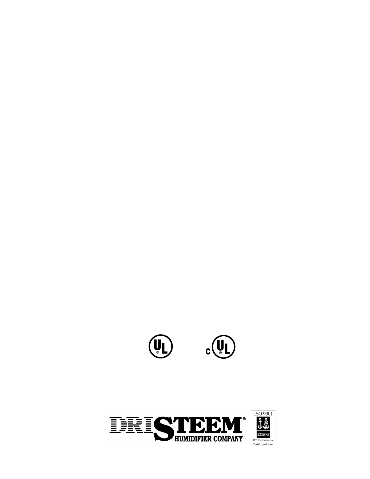
Water Supply Shut Off
Valve (not provided)
To Water Supply
Water Strainer
Automatic
Steam Valve
To Steam
Supply
Steam Trap
Condensate Return
Needle Valve
Water Seal
STS® AND STS®-DI HUMIDIFIERS
¼" NPT Fill
Make-Up Valve
Air Gap
Heat Exchanger
Skimmer Tube
Clean-Out Plate
Manual drain or Optional
Motorized Drain Valve
Open Drain
STS Humidifier
(For use with softened or
unsoftened water.)
This humidifier is designed for use
with either softened or unsoftened
water (preferably softened). The
probe-type level control system
requires water conductivity of 100
micromhos/cm (2 grains/gal) minimum
to function, and therefore will not
operate on water treated by reverse
osmosis or deionization. However,
STS humidifiers are available for use
with these water types. The standard
humidifier can be converted in the field
to a STS-DI model. See below.
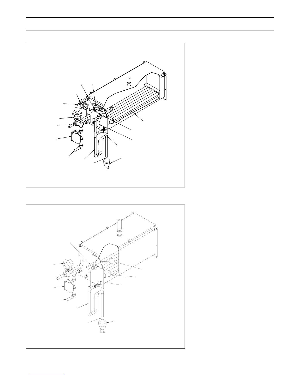
¼" NPT Water
Supply Minimum
25 psi Water
Pressure
Automatic
Steam Valve
Steam Trap
Condensate Return
OM-471
STS-DI Humidifier
(For use with demineralized
or reverse osmosis water.)
For use with deionized or reverse
osmosis water. This unit produces
chemical-free steam and reliable,
accurate humidification control. It is
virtually maintenance-free, with no
wasted water, heat, or downtime.
Float Valve
Heat Exchanger
Manual Drain Valve
Water Seal
Air Gap
Note: Drain piping material must be suitable for 212°F (100°C) water.
Open Drain
OM-487
3
Page 4
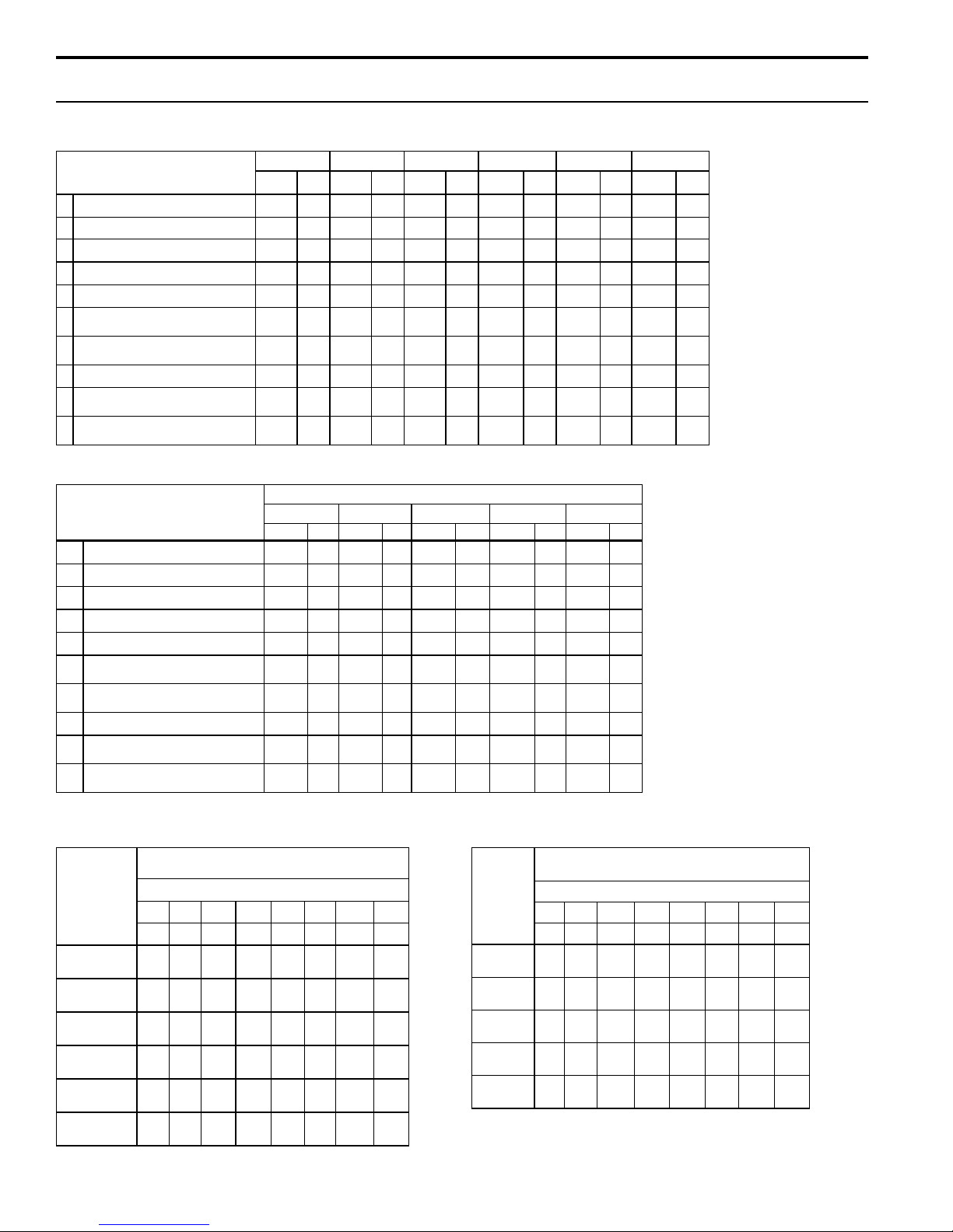
CAP ACITIES AND DIMENSIONS
Table 4-1: Mechanical dimensions for STS and STS-DI units with stainless steel heat exchanger(s)
noitpircseD
AthgiehllarevO 52.8156452.8156452.8156452.8156452.8156475.82527
BhtdiwecaF 57.4157357.4157352.9109452.8202752.8202752.82027
ChtgnelecaF 86.3200686.93010186.93010112.55004112.55004112.550041
DtelniylppusotmottobmorfecnatsiD 58.657158.657158.657158.657158.657158.6761
EteltuonruterotmottobmorfecnatsiD 53.35853.35853.35853.35853.35853.358
F
G
HregnahcxetaehotedismorfecnatsiD 52.33852.33852.33852.33852.33852.338
JtelniylppuS
KteltuonruteR
regnahcxetaehdnocesfo
regnahcxetaehdnocesfo
telniylppusotmottobmorfecnatsiD
teltuonruterotmottobmorfecnatsiD
Table 4-2: Mechanical dimensions for STS and STS-DI units with copper heat exchanger(s)
noitpircseD
AthgiehllarevO 52.8156452.8156452.8156452.8156475.82527
BhtdiwecaF 57.4157357.4157352.9109452.8202752.82027
ChtgnelecaF 86.3200686.93010186.93010112.55004112.550041
DtelniylppusotmottobmorfecnatsiD 36.607136.607136.607136.686136.6861
EteltuonruterotmottobmorfecnatsiD 95.30995.30995.30995.30995.309
F
G
HregnahcxetaehotedismorfecnatsiD 52.33852.33852.33852.33852.338
JtelniylppuS
KteltuonruteR
regnahcxetaehdnocesfo
regnahcxetaehdnocesfo
telniylppusotmottobmorfecnatsiD
teltuonruterotmottobmorfecnatsiD
S52-STSS05-STSS001-STSS002-STSCNS004-STSCNS008-STS
.nimm.nimm.nimm.nimm.nimm.nimm
--------------------05.41063
--------------------00.11582
TPN"
)02ND(
TPN"
)02ND(
.nimm.nimm.nimm.nimm.nimm
----------------82.41263
----------------42.11582
TPN"
)02ND(
TPN"
)02ND(
TPN"1
--
--
C52-STSC05-STSC001-STSC004-STSC008-STS
)52ND(
TPN"
)02ND(
--
--
TPN"
)02ND(
TPN"…1
)23ND(
TPN"1
--
--
--
--
--
)52ND(
TPN"
--
)02ND(
TPN"…1
)23ND(
TPN"…1
)23ND(
TPN"‰1
--
)04ND(
TPN"
--
)02ND(
rebmunledoM
--
--
TPN"…1
--
)23ND(
TPN"‰1
--
)04ND(
TPN"‰1
--
)04ND(
TPN"
--
)02ND(
TPN"…1
)23ND(
TPN"‰1
)04ND(
--
Table notes:
--
C= Copper
TPN"‰1
)04ND(
TPN"
)02ND(
Table notes:
S= Stainless steel
SNC= Stainless steel
without Teflon coating
--
For use with DI/RO
--
water only
Table 4-3: Capacities for units with
stainless steel heat exchangers
ledoM
rebmun
S52-STS
S05-STS
S001-STS
S002-STS
4
ISPaPkISPaPkISPaPkISPaPk
5430196310951301
01
5
52
11
hpp
h/gk
hpp
03
41
hpp
06
hpp
051
hpp
071
CNS004-STS**
hpp
212
CNS008-STS**
hpp
55
h/gk
hpp
72
011
h/gk
hpp
86
092
h/gk
hpp
77
293
h/gk
hpp
69
528
h/gk
hpp
03
h/gk
hpp
52
57
h/gk
hpp
05
041
h/gk
hpp
231
063
h/gk
hpp
871
255
h/gk
hpp
473
5901
h/gk
hpp
Table 4-4: Capacities for units with copper heat
exchangers
sregnahcxetaehleetssselniatshtiwseiticapactuptuO
)aPk(ISPerusserpmaetS*
41
53
h/gk
43
h/gk
46
h/gk
361
h/gk
052
h/gk
794
h/gk
61
hpp
h/gk
08
63
hpp
h/gk
051
86
hpp
h/gk
093
771
hpp
h/gk
736
982
hpp
h/gk
3221
555
hpp
Table 4-3 and 4-4 notes:
h/gk
* Steam pressure at connection to the STS steam valve (provided by DRI-STEEM)
ledoM
rebmun
ISPaPkISPaPkISPaPkISPaPk
5430196310951301
02
9
07
23
C52-STS
hpp
h/gk
hpp
05
32
C05-STS
hpp
001
C001-STS
hpp
003
C004-STS
hpp
056
C008-STS
hpp
051
h/gk
hpp
54
003
h/gk
hpp
631
085
h/gk
hpp
592
5721
h/gk
hpp
001
h/gk
hpp
86
002
h/gk
hpp
631
004
h/gk
hpp
362
027
h/gk
hpp
875
0051
h/gk
hpp
erusserpmaetS*
54
h/gk
19
h/gk
181
h/gk
723
h/gk
086
h/gk
** SNC = Stainless No (Teflon) Coating. For use with DI/RO water only.
sregnahcxetaehreppochtiwseiticapactuptuO
021
45
hpp
h/gk
042
901
hpp
h/gk
084
812
hpp
h/gk
097
853
hpp
h/gk
0061
627
hpp
h/gk
Page 5
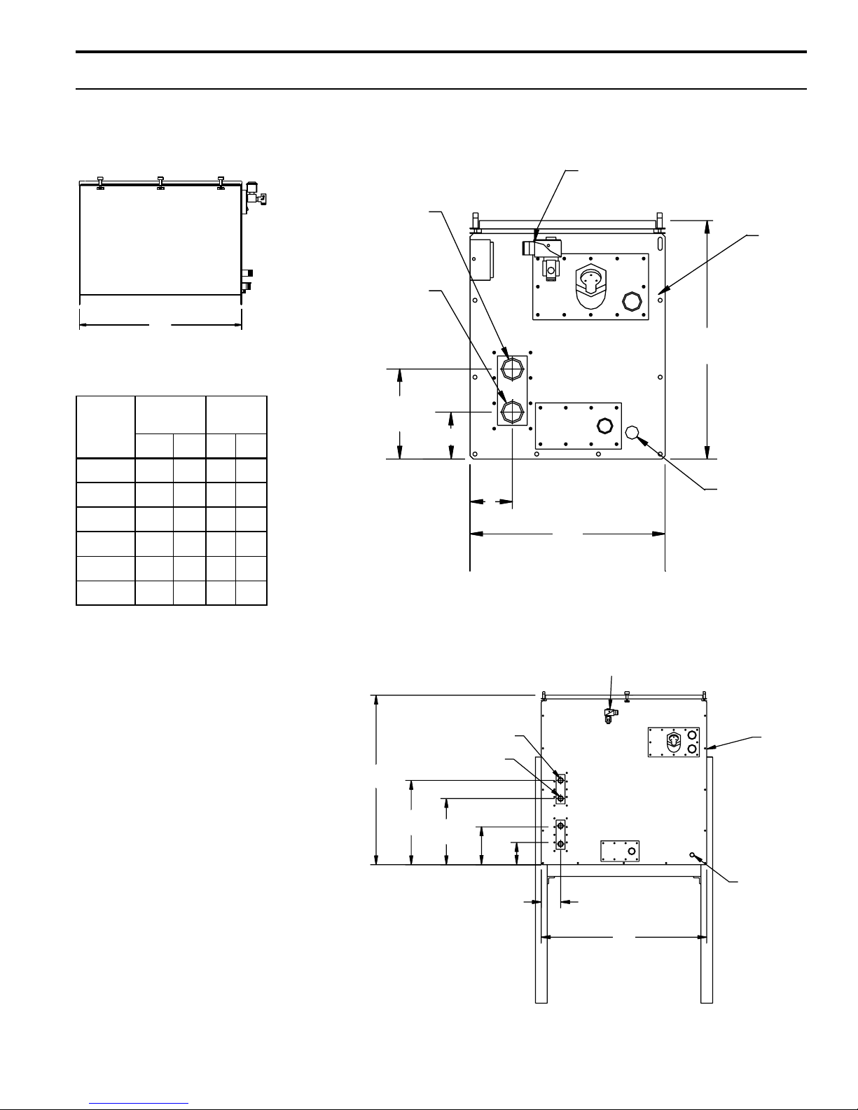
CAP ACITIES AND DIMENSIONS
STS and STS-DI® all sizes STS and STS-DI (single heat exchanger) sizes 25S&C, 50S&C,
100S&C, 200S, 400C, and 400SNC
Side view
C
Table 5-1: Humidifier weights
Front view
¼" NPT water makeup valve
J
K
A
5/16" dia.
mounting
bolt holes
ledoM
rebmun
52-STS 571975934
05-STS 63325152175
001-STS 05395193136
002-STS* 058683542111
004-STS* 059134023541
008-STS* 0541856014681
Table 5-1 note:
*Suspending from overhead
construction is not recommended
due to operating weight of unit.
gnitarepO
thgiew
sblgksblgk
gnippihS
thgiew
D
E
¾" drain
H
B
STS and STS-DI (dual heat exchanger) size 800C and 800 SNC
Front view
¼"NPT water
make up valve
5
/16" dia
J
K
A
mounting bolt
holes
G
F
E
D
H
B
Note:
See Tables 4-1 and 4-2 (page 4) for dimensional data.
¾" drain
OM-336
5
Page 6
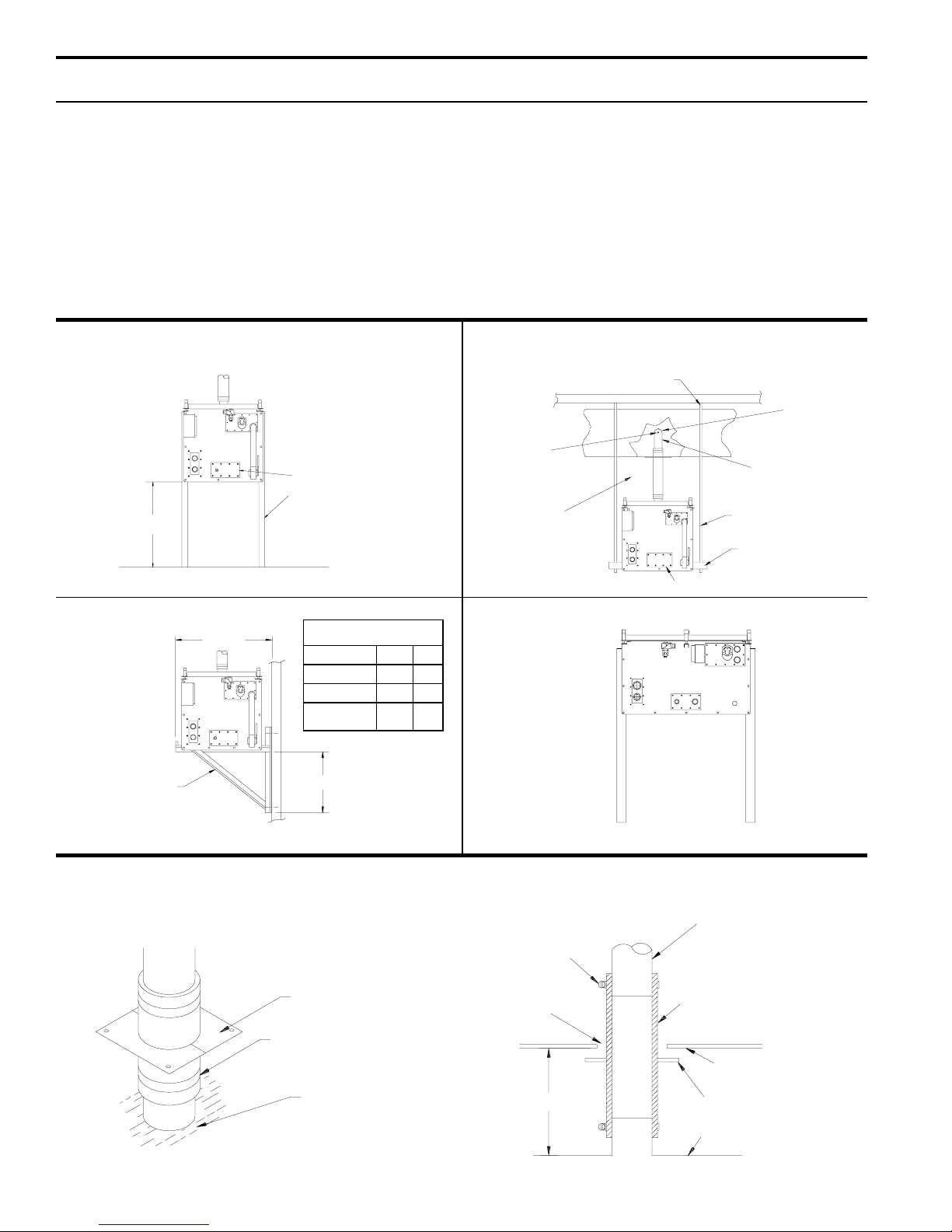
MOUNTING METHODS
Mounting Notes
1. For the electrode probe water level control and the
skimmer system to properly operate, the humidifier must
be mounted level in both directions.
2. Access (12" to 18" minimum) for periodic removal of the
top cover is recommended. In most cases, scale that
forms on the heat exchanger continuously flakes off as it
Figure 6-1: STS Mounting Options
1. Floor Stand
Clean-out
DRI-STEEM
*24"
*24" is standard, other lengths are optional.
support legs
(optional)
OM-504
forms and the loose scale settles to the bottom. A cleanout tray on the floor of the evaporator may be removed
periodically through the front clean-out opening.
3. Due to the size and weight of the STS
®
200, 400 and
800 units, the trapeze hanger and wall brackets are not
recommended.
2. Trapeze Hanger (see note 3 above)
Secure rods to overhead
construction suitable for the load
Inverted
U-tube
3/8"-16
Support Rod
Provide 12" to 18"
clearance under duct
for cover removal
OM-505
Clean-out
For best absorption
U-tube should be at
mid height of duct
Threaded rod of size
required
Angle or channel of
size required
3. Wall Brackets (see note 3 above)
A
Optional wall
brackets, two
required
snoisnemiD
tinUAB
05,52STS"¾51"62
001STS"¾02"23
,002STS
008,004
B
----
OM-517
4. Cradle
Models STS 200,
STS 400C and 800C
require cradle.
5. Mounting STS Unit on Underside of Duct
Mounting humidifier 12" to 18" below duct recommended to facilitate cover removal.
Two-Piece Escutcheon Plate
fastens to bottom of duct
(duct omitted for clarity)
Vapor Hose
Cut hole in duct large
enough to allow passage
of hose clamp
Clamp
OM-755
Steam Dispersion
Tube
Vapor Hose
Bottom of Duct
Cover of STS Humidifier
OM-65
6
12" to 18"
Two-Piece Escutcheon Plate
Cover of STS Humidifier
OM-66
Page 7
MOUNTING METHODS
6. Mounting STS Unit Away from Duct(s) Using Vapor Hose
Vapor hose. (Pitch back min. 2" per foot to humidifier with supports to
prevent pockets.) Maximum length 10'. Humidifier must be mounted level.
Stainless steel
dispersion tube in
middle of duct.
Maximum tube
length = 10'.
OM-50
7. Mounting STS in Air Handling Unit (with U-Tubes)
Gasketed Access Door
Air Handling Unit Casing
Airflow
Supply Air Duct
Set unit level. Locate unit so that steam
dispersion assembly is in the most active part
of the air stream.
Airflow
Humidifier
Centered in Air
Handling Unit
Outdoor and Return Airflow
into Air Handling Unit
Airflow
Filter and Mixing Box
Air Handling Unit Coil Section
OM-276
7
Page 8
PIPING
Steam Supply
The heat exchanger in the STS® standard humidifier is
designed for a maximum steam pressure of 15 psi. The
steam valve, trap and strainer are shipped loose for field
installation.
Make-up Water Piping
Either cold or hot water can be used for make-up. The
water pressure must be between 25 to 100 psi. If the
water pressure is above 60 psi and/or water hammer
would be objectionable, a pressure reducing valve or
shock arrester should be installed. Even though the STS
has an inner 1" air gap, some local codes may require a
vacuum breaker in the water supply pipe.
Make-up Water Considerations
When non-metallic water piping is used, it must be rated
to withstand 212°F or greater temperature. If not, the final
3 feet connected to the humidifier should be metallic and
should not be insulated.
As part of the fill valve assembly, a needle valve is
provided. It restricts the rush of cold water entering the
evaporating chamber during each fill cycle. The needle
valve adjusted to minimize output disruption and potential
"water hammer" (water pressure must be between 25 and
100 psi).
The STS Humidifier works with all water types - potable,
softened or demineralized make-up water.
Preferably this humidifier should be supplied with
softened water. The probe type level control system
requires water conductivity of 100 micromhos/cm
(2 gr/gal) minimum to function and will not operate
with water treated by reverse osmosis or deionizing
process. Specially designed STS DI humidifiers are
available for use with these water types.
Softened Water
There are two major advantages derived from using
softened water instead of potable water (assuming the
untreated supply water hardness is over 10 grains per
gallon): maintenance and accuracy of control.
Maintenance
The skimmer, in conjunction with softened water, is an
unbeatable combination for eliminating scale formation in
the evaporating chamber. Several seasons of operation
with no need for cleaning is normal, even with water
having up to 30 grains of dissolved minerals per gallon
prior to being softened.
Accuracy of Control
Reducing the higher skimmer quantity and eliminating the
drain/flush cycle (both of which are accomplished by the
use of softened water) improves controllability.
Softened Water Reduces Water Usage
The fewer number of make-ups per unit of time and the
lesser the amount of water per make-up, the more "on
time" or actual humidifying time will occur thus improving
control accuracy. This is especially true when modulating
control of the steam input to the humidifier is used.
Figure 8-1:
This piping method is recommended when obstruction
prevents dispersion tube from being continuously pitched
back to the humidifier.
4" Minimum
Air Gap
OM-702
8
Obstruction
STS Humidifier
H
¾" Tubing
Funnel or Floor
Drain*
* Note: Refer to governing codes
for drain pipe size requirements.
Page 9

PIPING
Potable Water
For water less than 10 grains per gallon hardness the
skimmer system alone, without softening, usually provides a full season or more of humidification without a
need for cleaning the evaporator.
For water hardness above 10 grains per gallon and where
softened water is not available the timer operated drain/
flush feature is available. The humidifier control module
contains an integral adjustable timer which accumulates
the "on" or actual humidifying time of the unit. When this
accumulated time reaches the amount previously pre-set
in the control module, the drain/flush cycle is activated.
Drain Piping
A drain line should be extended from the skimmer/drain
connection to a sanitary waste. A water seal should be
provided in the drain line of sufficient height to contain
the pressure developed within the humidifier. Without this,
steam will be forced through the drain line which would be
objectionable. The depth of the water seal must be
sufficient to overcome the static pressure of the air
handling system plus the pressure developed by the
humidifier itself. (Refer to table 11-1 on page 11.)
Figure 9-1: This piping method is recommended when
humidifier must be mounted higher than the duct.
STS
Humidifier
1½" S.S. Tubing Tee
(supplied by others)
H
Air Gap
Funnel or Floor
Drain*
OM-703
* Note: Refer to governing codes
for drain pipe size requirements.
9
Page 10

PIPING
Figure 10-1 - Piping of STS® from an overhead steam
supply main with condensate returned to a vented gravity
flow return system. Note the steam trap installed at the
bottom of the branch rise feeding the steam valve of the
STS. Failure to install this trap will cause water hammer,
which could damage the STS heat exchanger.
Figure 10-1 Figure 10-2
Steam Main
Alternate Vacuum
Breaker Position
Figure 10-2 - Depicts the same supply configuration,
however the condensate return main is above the STS
and the condensate must be "lifted". Lifts in excess of six
inches per PSI steam inlet pressure should not be
attempted. Check valves down stream of both steam
traps are necessary to avoid hammer and associated
problems.
In both instances, Figure 10-1 and 10-2, vacuum breakers
are necessary to ensure condensate can drain from the
heat exchanger when the steam valve closes.
Steam Main
Alternate Vacuum
Breaker Position
12"
End of
Branch Trap
(by others)
Trap "A"
12"
Vacuum Breaker
(by others)
Swing
Check
Valves
(by
others)
Gravity Condensate Return
OM-586
12"
12"
Vacuum Breaker
(by others)
Swing Check Valves (by others)
To Elevated
Condensate Return
OM-586
10
Page 11

PIPING DIAGRAMS: STEAM, WATER AND DRAIN
Figure 11-1: Standard STS
Water Supply Shut Off
Valve (not provided)
To Water Supply
Automatic Steam Valve
To Steam Supply
Steam Trap
Condensate Return
®
Needle Valve
Water Strainer
Water Seal
¼" NPT FillMake-Up Valve
H
Air Gap
Heat Exchanger
Skimmer Tube
Clean-Out Plate
Manual drain or Optional
Motorized Drain Valve
Open Drain
OM-471
Note: Refer to governing codes on
drain pipe sizing requirements.
Table 11-1: Water Seal Height Recommendations
Water S e a l H e ig ht (H )
Unit Output
(pounds per hour)H(inches)
5-138 12
139-183 15
184 and higher 18
Figure 11-2: STS-DI
¼" NPT Water
Supply Minimum
25 psi Water
Pressure
Automatic
Steam Valve
Steam Trap
Condensate Return
Water Seal
Air Gap
Note: Drain piping material must be suitable for 212°F (100°C) water.
Manual Drain Valve
H
Open Drain
Float Valve
Heat Exchanger
OM-487
11
Page 12

PIPING DIAGRAMS: STEAM, WATER AND DRAIN
Figure 12-1: Alternate Water Seal and Valve Piping
Used when water seal must be elevated above flow line of
drain connection (Humidifier near floor). Water seal height
recommendations refer to table 11-1.
Water Seal Flow
Line Cannot Be
Above Skimmer
Skimmer
Drain Connection
H
Air Gap
ELECTRICAL
The electrical supply is 120 volt, single phase. The
control cabinet should be mounted in a location for
service. All wiring must be in accordance with all governing codes and the STS® wiring diagram. A wiring diagram
is inside the control cabinet. The wiring between the
control cabinet and the humidifier must be 105°C rated
wire.
Manual Or Optional
Motorized Drain Valve
Note: Flow Line At
This Point Must Not
Be Above Flow Line
Open Drain
At Drain Connection
OM-489
Please refer to the VAPOR-LOGIC2 O&M for electrical
connection information on the controller.
Caution: Only qualified electrical personnel should
perform installation and start-up procedures.
12
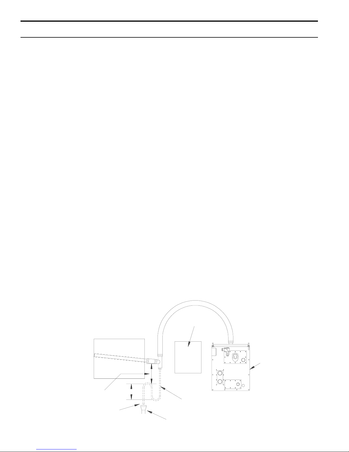
Page 13

STEAM DISPERSION INSTALLATION
STS Dispersion Tube Installation with Condensate Drain
Vapor Hose
• Vapor hose should be supported
to prevent sags or low spots and
to maintain a minimum pitch of 2"
per foot back to the humidifier.
• When mounting the humidifier
above the level of dispersion tube,
see page 9.
Failure to follow the above recommendation may result in excessive
back pressures being imposed on
the humidifier. This in turn may lead
to dispersion tube(s) spitting, lost
water seals or leaking gaskets.
When distance between humidifier
and the dispersion tube(s) exceeds
10 feet, consult factory for special
recommendations.
Hard Piping
• Hard piping should have a
minimum I.D. of 1½".
• A minimum pitch of 2" per foot
back to the humidifier should be
maintained.
• 90° elbows are not recommended,
use two 45° elbows one foot apart
instead.
• Thin wall tubing will heat up faster
and cause less start up loss than
heavywall pipe.
• Insulating the hard piping will
reduce the loss in output caused
by condensation.
Tube Mounting
• Mount dispersion tube level.
• Best vapor absorption occurs
when dispersion tube discharges
against the air flow.
**Return line piping material
must be suitable for 212° F
(100°C) water.
Minimum Condensate Drain Line
Sizing
• One or two tubes: 3/4" I.D.
• Three or more tubes - 1" I.D.
Figure 13-1: Single Tube
2.5"
Movable Escutcheon Plate (Plate
can be mounted within limits of 2.5".)
1.5"
2.5"
OM-351
3.25"
3.25"
3.25"
3.25"
3.25"
3.25"
¼" NPT
End
Figure 13-2: Multiple Tube with
Condensate Wasted
to Floor Drain
Dispersion Tube
1-½" Dia. Vapor
Hose or Hard
Tubing
STS® Humidifier
OM-1020
Water Seal
(5" approx.)
Insertion Length
Pre-molded High Temperature
Resin Steam Inserts
½" O.D.Copper
Tubing (condensate drain)
Dispersion
Tube
Duct
6" Min.
½" O.D. Condensate
Drain Tube
Condensate Drain Tube by
Others** (3/4" minimum)
Floor Drain*
* Note: Refer to governing codes
for drain pipe size requirements.
Figure 13-3: Multiple Tube with Condensate Return to Humidifier
Dispersion Tube
Duct
Dispersion Tube
1-½" Dia. Vapor
Hose or Hard
Tubing
STS Humidifier
½" Air Vent
6" Min.
Water Seal
(5"
approx.)
½" O. D. Condensate
Drain Tube
Refer to Water Seal Height
table 17-1, page 17
Mounting
Bracket
Mounting
Bracket
Air Flow
Air Flow
OM-1021
¾" Condensate Return
Connection (on face plate)
Condensate Drain
Tube by Others ** (3/4" minimum)
* Note: Refer to governing codes
for drain pipe size requirements.
13
Page 14

STEAM DISPERSION INSTALLATION
Selecting the Location:
A. It is very important that the dispersion method be
located where the water vapor being discharged will
be carried off with the airstream and will not cause
condensation or dripping from the duct.
B. In general, the dispersion method is best placed
where the air can most readily absorb the moisture
being added without causing condensation at or after
the unit. This will normally be after the heating coil or
where the air temperature is highest.
C. Do not place the dispersion method too close to the
intake of a high efficiency filter. The filter may
remove the visible moisture and become waterlogged.*
D. Do not place dispersion method where water vapor
will impinge on a metal surface.
E. Do not place the dispersion method too close to a
split in the duct. The unit may put more moisture in
one branch then the other.
Installation Above Valuable Equipment
Water piping and humidifiers should not be installed
above expensive apparatus or equipment. The risk of a
broken water pipe, leaking valve gland, condensation or
other water leaks may occur causing serious damage
and costly repairs to the equipment below.
Where this type of installation cannot be avoided install a
drip tray constructed of galvanized sheet under the
humidifier, valve, etc. to catch any possible water drip.
It is advisable to terminate the drain above an open floor
drain. The overflow from the STS
®
should be piped
separately to a floor drain rather than the drip pan.
Figure 14-1: Installation Above Valuable Equipment
This length of duct should have sealed seams.
Humidifier2'
Air Flow
STS Humidifier
Drip Pan
Refer to governing codes regarding drip pan
depth and drain pipe size requirements.
* The distance steam will travel within a given airstream is predictable and can be determined using the STS catalog.
If this has already been done, the travel distance should be specified; if not, consult the STS catalog or contact you
DRI-STEEM representative or the DRI-STEEM factory.
*
Vapor Absorption Area
Allow 12"-18" space for cover
removal during maintenance.
Ceiling Line
OM-59
14
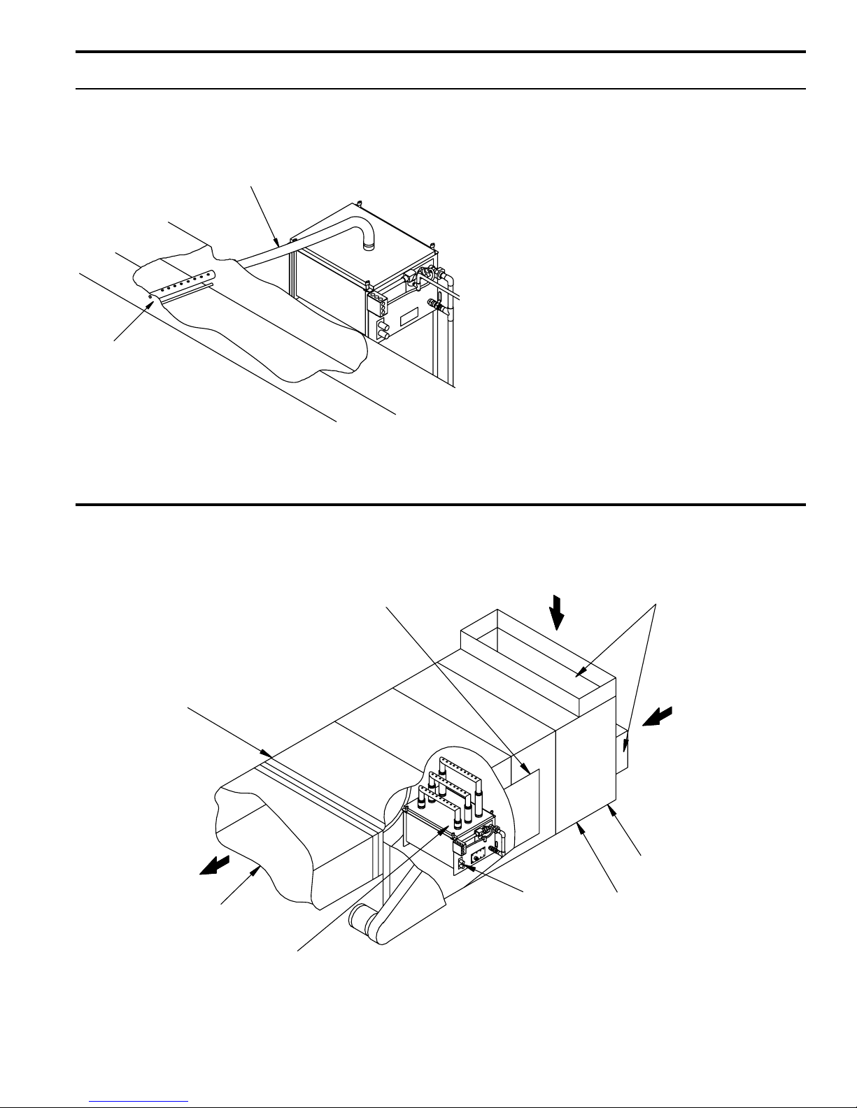
Page 15

RAPID-SORB® ASSEMBLY AND INSTALLATION
Horizontal Duct Installation
1. Unpack Shipment and verify receipt of all
RAPID-SORB components with packing list. Report
any shortages at once to the DRI-STEEM factory.
2. Provide necessary access around and into duct work.
3. Locate 1" x 1½" stainless steel channel inside duct
centered between duct side walls. Hang channel from top
of duct with the two mounting holes provided.
4. Locate dispersion tubes and slide hose cuffs over end
of each tube, include a pair of hose clamps.
5. Note direction of air flow within duct then arrange each
dispersion tube so steam will blow perpendicular to the air
flow. Use the hex bolts provided to attach tubes to
overhead 1" x 1½" channel. Do not secure. On units with
the header mounted outside the duct, punch-out necessary clearance holes in base of duct to slide dispersion
tubes up from bottom (see figure 15-2).
6. For a Header Inside the Duct (See figure 15-1.):
Punch or cut out necessary clearance holes for
RAPID-SORB header. Slide header into the duct, position
header and slide the dispersion tube hose cuffs or slip
couplings over the header dispersion tube nipples.
Position the header so vertical dispersion tubes are
perpendicular to duct and pitch the header toward condensate drain. Secure header to the mounting bracket. Use
escutcheon plates to secure header where it enters the
duct.
7. Connect a condensate drain to header, provide the
water trap as shown and run to open drain, sized per
governing codes.
8. Attach the header swivel hose connector to main
header using the hose cuff and clamps provided, do not
secure.
9. Route the necessary number of vapor hoses or pipes
from the humidifier tank, position connector to accept the
hoses or pipes and secure.
Note: Refer to page 10 for vapor hose information on
routing and for alternate vapor hose installation methods.
Figure 15-1: RAPID-SORB Unit
Header Inside Duct
S.S. Dispersion
Tube
Orificed
Tubelets
Hose Cuff
Pitch 1/8" per foot (minimum)
Header
Optional companion
flange connection
1" x 1-1/2" 304 S.S. Channel
Condensate
Drain, 3/4" NPT
3/4" Copper Min.
Air Gap
Open Drain
Duct
Support Bolt
(By Installer)
6"
Min.
5" Min.
Check that the dispersion tubes release steam perpendicular to the air flow. Secure tubes to the overhead
channel. Secure the channel to the duct, and secure hose
cuffs or slip couplings over tube and header tube nipples.
For a Header Outside the Duct (see figure 15-2.):
Position header under dispersion tubes, then slide hose
cuffs or slip couplings over header dispersion tube
nipples.
Position the header so dispersion tubes are perpendicular
to duct and pitch the header to condensate drain. Secure
dispersion tubes in place with the tube escutcheon plates
provided.
Check the position of the tubes for steam release perpendicular to the air flow. Secure tubes to the overhead
channel, and secure channel to the duct. With header
pitched to condensate drain, slip hose cuffs or slip
couplings over tube nipples and secure.
Figure 15-2: RAPID-SORB Unit
Header Under Duct
Duct
Bolt
Support
Bracket
Orificed Inserts
View A-A
Hose Cuff
Hose
Clamps
STS
S.S. Dispersion
Tube
Pitch 1/8"/foot (min.)
Header
Connection
A
A
Condensate
Drain, ¾" NPT
¾" Copper Min.
Open Drain
1" x 1½" 304S.S.
Duct
Escutcheon
Plate
Mounting
Bracket
6" Min.
5" Min.
Air Gap
15
Page 16

RAPID-SORB® ASSEMBLY AND INSTALLATION
Vertical Duct Installation
Install the RAPID-SORB® with dispersion tubes and
header pitched to condensate drain as shown in figures
16-1,16-2, and 16-3.
Figure 16-1: Plan View
1/8" per foot
pitch minimum
Steam
Supply
Figure 16-3: Elevation View
Tube with Drain
3/4" NPT Coupling
6" Min.
5" Min.
5" Min.
Airflow
Recommended 1/4"
per foot pitch
1/4" NPT
Drain
Condensate
Drain
Figure 16-2: Elevation View
Tube without Drain
Airflow
Recommended 2" per
foot pitch
6" Min.
5" Min.
Table 16-1*: Maximum Steam Carrying Capacity in
Lbs/Hr and Kg/Hr
Vapor Hose
Hose I.D.
1
1
/2" (38 mm) 150 lbs/hr 68 kg 11/2" (38 mm) 150 lbs/hr 68 kg/h
2" (50 mm) 250 lbs/hr 115 kg 2" (50 mm) 220 lbs/hr 100 kg/h
Developed Length
of 10’ (3.0 Meters)* *
Copper or Stainless Steel Tubing and
Schedule 40 Steel Pipe
Tube or
Pipe Size
3" (75 mm) 450 lbs/hr 205 kg/h
4" (100 mm) 750 lbs/hr 340 kg/h
5" (125 mm) 1400 lbs/hr 635 kg/h
6" (150 mm) 2300 l bs/hr 1043 kg/h
Base on Developed
Length of 20’ (6 Meters)**
Open Drain
- - - - Dashed line indicates field piping.
16
* Based on total pressure drop in piping/hose of 5" (12.65 mm) W.C.
** For developed length add 50% to measured length for pipe fittings.
Note: To minimize lossof humidifier capacity and efficiency, it is recommended
that tubing/piping be installed.
Page 17

START-UP AND OPERATION
Figure 17-1: Reliable Electronic Probe Control
Maintains Water Level
Probe
Housing
Probe Rod
Water Levels
Probe
OM-270
A- Fill Valve Closes
B - Fill Valve Opens
C - Low Water Indication
A simple three-probe conductivity sensor cycles a
solenoid-operated water fill valve to maintain the proper
water levels.
The STS® humidifier is provided with a standard
VAPOR-LOGIC
®
microprocessor control system, see the
2
VAPOR-LOGIC2 Installation and Operations Manual for
more information. Then continue reading this manual
beginning at the maintenance section on page 20.
Water Control with VAPOR-LOGIC
2
When the power is activated the solenoid-operated water
fill valve will open, filling the evaporating chamber. Filling
will continue until water reaches level A, at which time the
fill valve will close. To ensure that the water seal is filled
with water, disconnect probe plug and cable from probe
rod assembly (located on face plate), allowing the fill
valve to re-energize and overfill humidifier tank. This
process will take only seconds; probe plug and cable
must then be reconnected.
Water Refill
During operation, the water line will drop to level B. At this
level the fill valve opens, and remains open until the water
line returns to level A.
Adjustable Surface Skimmer
Each time the evaporating chamber refills, the upper
¼" of water is immediately drained off through the skimmer. This carries away the mineral residue formed during
the previous evaporating cycle. This skimming action
effectively removes most of the mineral concentration in
much the same way as the surface blowdown does in a
steam boiler. This simple device greatly reduces the
frequency of cleaning the evaporating chamber.
Note: Preferably this humidifier should be supplied
with softened water. However, the probe type level
control system requires water conductivity of 100
micromhos/cm (2 grains/gal) minimum to function
and may not operate in water treated by the reverse
osmosis or deionizing process. Specially designed
STS Model DI humidifiers are available for use with
these water types.
17
Page 18

RECOMMENDED MAINTENANCE
Caution: Allow unit to cool before performing any mainte-
nance. Manually open the drain valve and the fill valve
will be energized. Let the fill water run until the tank is
cooled then shut off the contractor/field installed supply
water valve.
STS® is designed to deal with dissolved minerals in one
of two ways depending on the degree of hardness. For
light to moderate hardness (up to 10 grains per gallon)
the surface skimmer action plus periodic cleaning is
usually adequate. For high mineral content water (above
10 grains per gallon) a periodic drain and flush along with
periodic cleaning may be helpful.
The frequency of cleaning will be dictated by water
condition and evaporation load.
Caution: When performing maintenance on the STS
always turn off electric power to control panel. Close steam
supply and water make-up valves.
Seasonally or as Required
1. Cleaning Tank
Remove loose scale in humidifier tank before the build-up
reaches the underside of the heat exchanger(s).
Summer Maintenance
After the humidification season, a complete inspection and
cleaning of the heat exchanger, probe control, skimmer,
and water chamber is recommended. After cleaning, the
unit should remain empty until humidification is required.
On units with TEFLON® coated heat exchangers, do
not use a sharp object when cleaning. Cuts or
scratches on the heat exchanger will impair its ability to
shed scale during operation, and could cause the TEFLON
to separate from the metal surface.
Adjusting the Surface Skim Bleed-Off Quantity
The skim time determines the quantity of water skimmed
with each fill cycle. The skim time is field adjustable
using the VAPOR-LOGIC2 keypad.
Model STS®-DI Only
The humidifier should be inspected for leaks at least
annually. All safety devices in the control cabinet should
be cycled on and off to verify that they are functioning.
Cleaning the Evaporating Chamber
As long as mineral-free water is used in the STS-DI
humidifier, no cleaning or flushing of the evaporating
chamber should be necessary.
2. Cleaning Probes
Remove cap assembly and unscrew the probe holder from
the STS unit. The scale will easily flake off from the
sensing probes. The sensing portion (bottom 3/8") of the
probe should be brushed clean with stainless steel wool.
Re-install the probe holder with arrows up and “top”
marking at the top.
3. Cleaning Skimmer Tube
Remove the elbow section of the skimmer and rotate
tube so that loosened material will drop out. Loosen
deposits with a long tool such as a screwdriver or
section of small diameter pipe and reassemble elbow.
Skimmer drainage should be verified by visual inspection once per week. Water should drain from skimmer
drain pipe after each fill cycle. (For cleaning piping,
disconnect and flush out. If mineral deposits have
restricted the flow, replace piping.)
4. Inspect Gaskets
Replacement procedures are provided with new
gaskets.
18
Page 19

STS-DI START-UP AND RECOMMENDED MAINTENANCE
Introduction
After the system has been properly installed and
connected to both electrical and water supplies, it may
then be started.
Mounting
Check mounting to see that unit is level and securely
supported before filling with water.
Piping
Verify that all piping connections have been completed
as recommended and that steam and water pressures
are available.
Electrical
Verify that all wiring connections have been made in
accordance with the STS® wiring diagram.
Control System
For VAPOR-LOGIC
to the Installation and Operations Manual enclosed with
the product shipment.
®
microprocessor control system, refer
2
Control Circuits
a) Adjust humidistat to “call” setting.
b) Open shut-off valve on water supply line.
Water should flow through float valve.
c) Turn electric power on to control cabinet.
d) Fill the water seal in drain line by manually
opening drain valve for a few seconds.
e) Open steam stop valve. Steam should be heard
passing through the automatic steam valve into the
humidifier heat exchanger.
f) Check out function of field installed air flow
switch, high limit duct humidistat, and controlling
humidistat to ensure that they are in control of
steam valve.
Recommended Maintenance-STS-DI System
(deionized water)
The STS-DI humidifier does not require regular maintenance. A periodic visual inspection is recommended to
identify gasket or piping leaks. Control circuit and
safety switches should be checked to verify they
properly control the steam valve.
Caution: Overtightening cover will cause leaks.
All cover knobs are turned down at the factory until
the bottom of the knob makes contact with the
flange, then one half turn further. If more compression is required, turn all knobs a half turn more. Do
not turn knobs more than a half turn before identifying that a leak still exists.
19
Page 20

TROUBLE SHOOTING GUIDE
Symptom Possible Cause Recommended Action
Humidifier Will Not Heat No control transformer output.
Humidistat is not calling.
Saftey controls open (high limit,
air proving, etc...)
Faulty control board.
Probe corrosion.
Steam stop valve closed.
Steam trap plugged.
Low or no steam.
Steam strainer plugged.
Humidifier Will Not Fill No water pressure.
Faulty water fill valve.
Plugged water strai ner.
Plugged valve.
Faulty control board.
Humidifier Does Not Stop Filling Lack of tank-to-probes continuity.
Water conductivity less than 100
micromhos/cm minimum (2 grains
per gallon)
Verify control voltage. Set humidistat to
"call". Inspect for faulty humidistat.
Check safety controls.
Verify control voltage and probe. Wires
are connected correctly.
Replace probes*.
Verify val ve is opened.
Clean trap body.
Verify steam is present.
Clean strainer.
Verify manual water supply valve is
open.
Verify action of fill solenoid valve, verify
contol voltage present at coil. Audible
click should be heard as solenoid
operates.
Open strainer.
Clean valve.
Verify control voltage.
Jumper terminals 1 & 3 if water sops,
verify tank ground to term 3; check
water supply conducti vi ty; then consult
factory .
20
Manual drain is not fully closed.
Fill valve is stuck open.
Fill valve installed backwards.
Low Output Automatic drain valve not seating.
Manual drain is not fully closed.
Excessive skimming amount.
Fill valve is stuck open.
Low supply steam pressure.
Steam valve inoperable.
Steam trap blocked.
Scale coated heat exchanger.
Make up Water Va lv e Sh ort C irc uits El ectrode probes may be
incorrectly wired.
Probes are scale coated.
*Although the three stainless steel electrode probes will eventually erode due to corrosion they are usually functional for up to approximately 5000
hours of operation.
Close manual ball valve.
Check valve for foreign matter.
Check for correct water flow, through
valve, note arrow.
Clean ball and seat of valve.
Close manual ball valve.
Red uce ski mme r o r skim time.
Check valve for foreign matter.
Check steam supply pressure.
Not opening fully.
Not passing condensate.
Clean heat exchanger.
Confirm that wi ring agrees with
diagram.
Clean probes.
Page 21

Figure 21-1: STS® Humidifier
REPLACEMENT P ARTS
Table 21-1: STS Humidifier Table 21-1: continued
No. Description Part No.
1 Tank, STS-25 164404-025 *
1 Tank, STS-50 164404-050 *
1 Tank, STS-100 164404-100 *
1 Tank, STS-200/400 164404-400 *
1 Tank, STS 800 164404-800 *
2 C ov er, STS-25 165359 *
2 C ov er, STS-50 165360 *
2 C ov er, STS-100 165365 *
2 C ov er, STS-200/400/800 165369 *
3 Gasket, Cover, STS-25 160690-224 *
3 Gasket, Cover, STS-50 160690-240 *
3 Gasket, Cover, STS-100 160690-340 *
3 Gasket, Cover, STS 200/400/800 1606 90-200 *
4 Knob, T-Handled Utility 700725
5 Heat Exchanger, STS-25S 164420-101 *
5 Heat Exchanger, STS-50S 164420-102 *
5 Heat Exchanger, STS-100S 164420-103 *
5 Heat Exchanger, STS-200S 164420-104 *
* Specify humidifier model and serial numbers when ordering.
No. Description Part No.
6 Heat Exchanger, STS-25C 1 64 43 6-1 01 *
6 Heat Exchanger, STS-50C 1 64 43 6-1 02 *
6 Heat Exchanger, STS-100C 164436-103 *
6 Heat Exchanger, STS-400/800C 164436-104 *
7 Support, Heat Exchanger Mtg Plate 124437
8 Cl ean Out Plate 165470
9 Gasket, Clean Out and Mtg Plate 308220
10 Valve, ¾" Ball (Manual Drain) 505011
11 Gasket, Probe/Float Pl ate 308220 -001
12 Probe Plate, STS-25/50/100 164411
12 Probe Plate, STS-200/400/800 164411-002
13 Baffle, Probe Plate 124443
14 Probe Plug 406050-002
15 Probe Assembly 406060
16 Valve, ¾" Electric (Auto D rain) 505400-001
17 F ill Valve, ¼" Solenoid, .125, STS-25, 50, 100 505084
17 F ill Valve, ¼" Solenoid, .281, STS -400, 800 505085
18 Strainer, ¼" Sediment 300050
19 Valve, Needl e ¼" 505070-001
* Specify humidifier model and serial numbers when ordering.
OM-518
21
Page 22

Figure 22-1: STS®-DI Humidifier
REPLACEMENT PARTS
OM-519
Table 22-1: STS-DI Humidifier Table 22-1: continued
No. Description Part No.
1 Tank, STS-25 164404-025 *
1 Tank, STS-50 164404-050 *
1 Tank, STS-100 164404-100 *
1 Tank, STS-200/400 164404-400 *
1 Tank, STS 800 164404-800 *
2 Cover, STS-25 165359 *
2 Cover, STS-50 165360 *
2 Cover, STS-100 165365 *
2 Cover, STS-200/400/800 165369 *
3 Gasket, Cover, STS-25 160690-224 *
3 Gasket, Cover, STS-50 160690-240 *
3 Gasket, Cover, STS-100 160690-340 *
3 Gasket, Cover, STS 200/400/800 160690-200 *
4 Knob, T-Handled Util ity 700725
No. Description Part No.
6 Heat Exchanger, STS-25C 164436-101 *
6 Heat Exchanger, STS-50C 164436-102 *
6 Heat Exchanger, STS-100C 164436 -103 *
6 Heat Exchanger, STS-400/800C 164436-104 *
7 Support, Heat Exchanger Mtg Plate 124437
8 Clean Out Plate 165470
9 Gasket, Cl e an Out and Mtg Pl ate 3 08 22 0
10 Valve, ¾" Ba l l (Manual Drai n) 505011
11 Gasket, Probe/Float Pl ate 308220-001
12 Float Plate, STS-25/50/100 164410
12 Float Plate, STS-200/400/800 164410-002
13 Baffle, Probe Plate 124442
14 Float Valve Assembly STS 25-400 505210
14 Float Valve Assembly STS 25-800 505300
5 Heat Exchanger, STS-25S 164420-101 *
5 Heat Exchanger, STS-50S 164420-102 *
5 Heat Exchanger, STS-100S 164420-103 *
5 Heat Exchanger, STS-200S 164420-104 *
* Specify humidifier model and serial numbers when ordering.
22
* Specify humidifier model and serial numbers when ordering.
Page 23

REPLACEMENT PARTS
Figure 23-1: STS® Control Cabinet with VAPOR-LOGIC
®
Controls
2
Table 23-1: VAPOR-LOGIC
No. Description Part No.
1 Power Block 408300-001
2 Transformer 408960
3 Ground Lug 40925 0-017
4 LW430, Microprocessor Board 408641
5 LW440, Display Board 408651
®
Controls
2
OM-1044
23
Page 24

TWO-YEAR LIMITED WARRANTY
DRI-STEEM Humidifier Company (“DRI-STEEM”) warrants to the original user that its products will be free from
defects in materials and workmanship for a period of two (2) years after installation or twenty-seven (27)
months from the date DRI-STEEM ships such product, whichever date is the earlier.
If any DRI-STEEM product is found to be defective in material or workmanship during the applicable
warranty period, DRI-STEEM’s entire liability, and the purchaser’s sole and exclusive remedy, shall be
the repair or replacement of the defective product, or the refund of the purchase price, at DRI-STEEM’s
election. DRI-STEEM shall not be liable for any costs or expenses, whether direct or indirect, associated with
the installation, removal or re-installation of any defective product.
DRI-STEEM’s limited warranty shall not be effective or actionable unless there is compliance with all installation and operating instructions furnished by DRI-STEEM, or if the products have been modified or altered
without the written consent of DRI-STEEM, or if such products have been subject to accident, misuse, mishandling, tampering, negligence or improper maintenance. Any warranty claim must be submitted to DRI-STEEM in
writing within the stated warranty period.
DRI-STEEM’s limited warranty is made in lieu of, and DRI-STEEM disclaims all other warranties, whether
express or implied, including but not limited to any IMPLIED WARRANTY OF MERCHANTABILITY, ANY
IMPLIED WARRANTY OF FITNESS FOR A PARTICULAR PURPOSE, any implied warranty arising out of a
course of dealing or of performance, custom or usage of trade.
DRI-STEEM SHALL NOT, UNDER ANY CIRCUMSTANCES BE LIABLE FOR ANY DIRECT, INDIRECT,
INCIDENTAL, SPECIAL OR CONSEQUENTIAL DAMAGES (INCLUDING, BUT NOT LIMITED TO, LOSS OF
PROFITS, REVENUE OR BUSINESS) OR DAMAGE OR INJURY TO PERSONS OR PROPERTY IN ANY
WAY RELATED TO THE MANUFACTURE OR THE USE OF ITS PRODUCTS. The exclusion applies regardless of whether such damages are sought based on breach of warranty, breach of contract, negligence, strict
liability in tort, or any other legal theory, even if DRI-STEEM has notice of the possibility of such damages.
By purchasing DRI-STEEM’s products, the purchaser agrees to the terms and conditions of this limited
warranty.
14949 Technology Drive • Eden Prairie, MN 55344
Phone: (952) 949-2415 • Fax: (952) 949-2933
E-Mail: sales@dristeem.com • Web: www.dristeem.com
International Office:
Bell Place, Bell Lane • Syresham, Brackley • NN13 5HP, U.K.
Phone: +44 1280 850122
Fax: +44 1280 850124
E-Mail: 106277.1443@compuserve.com
Continuous product improvement is a policy of DRI-STEEM Humidifier Company therefore,
product features and specifications are subject to change without notice.
DRI-STEEM, RAPID-SORB, STS, VAPOR-LOGIC and VAPOR-LOGIC2 are Registered Trademarks of the DRI-STEEM Humidifier Company.
Form No. STSOM-0200 Copyright © 2000 DRI-STEEM Humidifier Company, Inc. Printed in the U.S.A.
24
TEFLON is a Registered Trademark of Dupont.
 Loading...