

DriSteem RO-200 series, RO-201, RO-202, RO-203 Installation, Operation And Maintenance Manual
Page 1

READ AND SAVE THESE INSTRUCTIONS
WATER TREATMENT
200 series
reverse-osmosis systems
Installation, Operation,
and Maintenance Manual
Page 2
WARNINGS AND CAUTIONS
Warnings and cautions
WARNING CAUTION
Indicates a hazardous situation that could result in death or
serious injury if instructions are not followed.
mc_051508_1145
WARNING
Attention installer
Read this manual before installing, and leave this manual with product owner. This product must be installed by qualifi ed
HVAC and electrical contractors and in compliance with local, state, federal, and governing codes. Improper installation
can cause property damage, severe personal injury, or death as a result of electric shock, burns, or fi re.
DriSteem Technical Support: 800-328-4447
Read all warnings and instructions
Read this manual before performing service or maintenance procedures on any part of the system. Failure to follow all
warnings and instructions could produce the hazardous situations described, resulting in property damage, personal
injury, or death.
Failure to follow the instructions in this manual can cause moisture to accumulate, which can cause bacteria and mold
growth or dripping water into building spaces. Dripping water can cause property damage; bacteria and mold growth
can cause illness.
If the IOM is missing, go to www.dristeem.com to download a replacement.
Shut down the energy source
Before performing service or maintenance procedures on any part of the system, verify that all energy sources are off.
Failure to shut down the energy source could result in fi re, explosion, electrical shock, and other hazardous conditions.
These hazardous conditions could cause property damage, personal injury, or death.
Contact with energized circuits can cause property damage, severe personal injury or death as a result of electrical
shock or fi re. Do not remove electrical panel cover/door or access panels until electrical power is disconnected.
Follow the shutdown procedure in th
the system.
e system IOM before performing service or maintenance procedures on any part of
Indicates a hazardous situation that could result in damage to or
destruction of property if instructions are not followed.
DRISTEEM RO 200 SYSTEM WATER TREATMENT SYSTEMS INSTALLATION, OPERATION, AND MAINTENANCE MANUAL
ii
Page 3
Warnings and cautions
WARNING
Disconnect electrical power
Disconnect electrical power before installing supply wiring or performing service or maintenance procedures on any
part of the humidifi cation system. Failure to disconnect electrical power could result in fi re, electrical shock, and other
hazardous conditions. These hazardous conditions could cause property damage, personal injury, or death.
Contact with energized circuits can cause property damage, severe personal injury, or death as a result of electrical shock
or fi re. Do not remove RO system electrical panel cover, heater terminal cover, or subpanel access panels until electrical
power is disconnected.
Follow the shutdown procedure in this manual before performing service or maintenance procedures on any part of the
system.
mc_052410_1510
Electric shock hazard
If the RO system starts up responding to a call for humidity during maintenance, severe bodily injury or death from
electric shock could occur. To prevent such start-up, follow the procedure below before performing service or maintenance
procedures on this RO system (after the tank has cooled down and drained):
1. Use Vapor-logic
2. Shut off all electrical power to the RO system using fi eld-installed fused disconnect, and lock all power disconnect
switches in OFF position.
3. Close fi eld-installed manual water supply shut-off valve.
mc_050808_1540
®
keypad/display to change control mode to Standby.
Fill in the following information for your records
Date of purchase
Customer's name
Model number
Serial number
___________________________________________________________________________________________________________
___________________________________________________________________________________________________________
___________________________________________________________________________________________________________
___________________________________________________________________________________________________________
DRISTEEM RO 200 SYSTEM WATER TREATMENT SYSTEMS INSTALLATION, OPERATION, AND MAINTENANCE MANUAL
iii
Page 4

Table of contents
WARNINGS AND CAUTIONS . . . . . . . . . . . . . . . . . . . . . . . . . . . . . . . . . . . . . . . . . . . . . . . . ii
OVERVIEW. . . . . . . . . . . . . . . . . . . . . . . . . . . . . . . . . . . . . . . . . . . . . . . . . . . . . . . . . . . . . . 2
System specifications . . . . . . . . . . . . . . . . . . . . . . . . . . . . . . . . . . . . 2
Controller . . . . . . . . . . . . . . . . . . . . . . . . . . . . . . . . . . . . . . . . . . . . 4
RO supply water requirements . . . . . . . . . . . . . . . . . . . . . . . . . . . . .5
Flow schematic . . . . . . . . . . . . . . . . . . . . . . . . . . . . . . . . . . . . . . . . 6
Component identification . . . . . . . . . . . . . . . . . . . . . . . . . . . . . . . . . 8
INSTALLATION . . . . . . . . . . . . . . . . . . . . . . . . . . . . . . . . . . . . . . . . . . . . . . . . . . . . . . . . . . . 9
OPERATION . . . . . . . . . . . . . . . . . . . . . . . . . . . . . . . . . . . . . . . . . . . . . . . . . . . . . . . . . . . 10
System operation . . . . . . . . . . . . . . . . . . . . . . . . . . . . . . . . . . . . . . 10
Initial system start-up . . . . . . . . . . . . . . . . . . . . . . . . . . . . . . . . . . . 10
System flush . . . . . . . . . . . . . . . . . . . . . . . . . . . . . . . . . . . . . . 10
Normal operations . . . . . . . . . . . . . . . . . . . . . . . . . . . . . . . . . . . . 10
Shutdown . . . . . . . . . . . . . . . . . . . . . . . . . . . . . . . . . . . . . . . . . . . 10
Start-up checklist . . . . . . . . . . . . . . . . . . . . . . . . . . . . . . . . . . . . . . 11
Start-up . . . . . . . . . . . . . . . . . . . . . . . . . . . . . . . . . . . . . . . . . . . . 12
Start-up procedure . . . . . . . . . . . . . . . . . . . . . . . . . . . . . . . . . . 12
Test operation . . . . . . . . . . . . . . . . . . . . . . . . . . . . . . . . . . . . . 12
Initial system start-up . . . . . . . . . . . . . . . . . . . . . . . . . . . . . . . . . . . 12
Operating do's and don't's . . . . . . . . . . . . . . . . . . . . . . . . . . . . . .13
Do . . . . . . . . . . . . . . . . . . . . . . . . . . . . . . . . . . . . . . . . . . . . . . . .13
Don't . . . . . . . . . . . . . . . . . . . . . . . . . . . . . . . . . . . . . . . . . . . . . . 13
Vapor-logic keypad/display . . . . . . . . . . . . . . . . . . . . . . . . . . . . . .14
Changing mode . . . . . . . . . . . . . . . . . . . . . . . . . . . . . . . . . . . . . . 15
Controller display activity definitions . . . . . . . . . . . . . . . . . . . . . . . . 15
Test outputs . . . . . . . . . . . . . . . . . . . . . . . . . . . . . . . . . . . . . . . . . . 15
Test run . . . . . . . . . . . . . . . . . . . . . . . . . . . . . . . . . . . . . . . . . . . . 15
Status screen . . . . . . . . . . . . . . . . . . . . . . . . . . . . . . . . . . . . . . 16
Diagnostics and Alarms . . . . . . . . . . . . . . . . . . . . . . . . . . . . . . . . . 17
Modbus, BACnet, LonTalk interoperability . . . . . . . . . . . . . . . . . . . . 18
DRISTEEM RO 200 SYSTEM WATER TREATMENT SYSTEMS INSTALLATION, OPERATION, AND MAINTENANCE MANUAL
iv
Page 5

Table of contents
MAINTENANCE . . . . . . . . . . . . . . . . . . . . . . . . . . . . . . . . . . . . . . . . . . . . . . . . . . . . . . . .
20
Maintenance information . . . . . . . . . . . . . . . . . . . . . . . . . . . . . . . . 20
Maintenance tips . . . . . . . . . . . . . . . . . . . . . . . . . . . . . . . . . . . . . . 20
When to change sediment and carbon filters . . . . . . . . . . . . . . . . . . 20
Changing cartridge filters . . . . . . . . . . . . . . . . . . . . . . . . . . . . . 20
When to clean or replace membranes . . . . . . . . . . . . . . . . . . . . . . .21
Replacing membranes . . . . . . . . . . . . . . . . . . . . . . . . . . . . . . . . . . 21
Tools . . . . . . . . . . . . . . . . . . . . . . . . . . . . . . . . . . . . . . . . . . .21
Procedure . . . . . . . . . . . . . . . . . . . . . . . . . . . . . . . . . . . . . . . . 21
Membrane cleaning in the RO system . . . . . . . . . . . . . . . . . . . . . . . 22
How does it work? . . . . . . . . . . . . . . . . . . . . . . . . . . . . . . . . . . . .22
Scale cleaning cartridge. . . . . . . . . . . . . . . . . . . . . . . . . . . . . . . . . 22
Cleaning procedure . . . . . . . . . . . . . . . . . . . . . . . . . . . . . . . . . . . . 22
Organic cleaning cartridge . . . . . . . . . . . . . . . . . . . . . . . . . . . . . . 23
Cleaning procedure . . . . . . . . . . . . . . . . . . . . . . . . . . . . . . . . . . . . 23
Storage . . . . . . . . . . . . . . . . . . . . . . . . . . . . . . . . . . . . . . . . . . . . 24
Membrane preservative cartridge . . . . . . . . . . . . . . . . . . . . . . . . . . 24
Preserving procedure . . . . . . . . . . . . . . . . . . . . . . . . . . . . . . . . 24
Flushing out preservative/restart procedure . . . . . . . . . . . . . . . . 24
System monitoring and record keeping . . . . . . . . . . . . . . . . . . . . . . 25
System operating log . . . . . . . . . . . . . . . . . . . . . . . . . . . . . . . . . . .26
Water quality test strips . . . . . . . . . . . . . . . . . . . . . . . . . . . . . . . . . 27
Water Quality Test Strips Sample Pack . . . . . . . . . . . . . . . . . . . . . . 27
REPLACEMENT PARTS . . . . . . . . . . . . . . . . . . . . . . . . . . . . . . . . . . . . . . . . . . . . . . . . . . . . 28
RO system (Models 201, 202, and 203) . . . . . . . . . . . . . . . . . . . . . 28
Subpanel . . . . . . . . . . . . . . . . . . . . . . . . . . . . . . . . . . . . . . . . . . . 30
Notes . . . . . . . . . . . . . . . . . . . . . . . . . . . . . . . . . . . . . . . . . . . . . . 31
ATTENTION INSTALLER
Read this manual before installing.
Leave manual with product owner.
DriSteem® Technical Support
800-328-4447
Where to find more information
Our website:
The following documents are available on our
web site: www.dristeem.com
• Water Treatment Systems Catalog
• Vapor-logic Controller Installation and
Operation Manual
DriCalc® sizing and selection software:
DriCalc, our software for system sizing and
selection, can be ordered at our web site.
Call us at 800-328-4447
Obtaining documents from our web site or
from DriCalc is the quickest way to view our
literature, or we will be happy to mail literature
to you.
WARRANTY . . . . . . . . . . . . . . . . . . . . . . . . . . . . . . . . . . . . . . . . . . . . . . . . . . . . . . . . . . . 32
Keypad/display and troubleshooting
The Vapor-logic Installation and Operation
Manual, which was shipped with your RO
system, is a comprehensive operation manual.
Refer to it for information about using the
keypad/display and Web interface, and for
troubleshooting information.
Download DriSteem literature
Most DriSteem product manuals are available
our website: www.dristeem.com
DRISTEEM RO 200 SYSTEM WATER TREATMENT SYSTEMS INSTALLATION, OPERATION, AND MAINTENANCE MANUAL
1
Page 6

OVERVIEW
System specifi cations
Table 2-1:
RO station electrical specifications and weights
Model Hz Motor HP Volts*/Amps Phase/Frequency
201
202 124 lbs. (56 kg) 148 lbs. (67 kg)
203 130 lbs. (59 kg) 154 lbs. (70 kg)
* 115V or 230V must be ordered specifi cally
** Tank bladder pressure = 28 psi, tank full at 50 psi
*** Noise measurements taken 6.5' (2 m) in front of the RO-200 water treatment system.
60 1/3
110-120
VAC/5.5A
(208-240
VAC/2.8A)
1/60Hz
NOTES:
1. All systems rated at 50°F (10°C) using 1000 ppm sodium chloride (NaCl)
solution. System capacity decreases signifi cantly with decrease in feed
water temperature.
Approximate
shipping weight**
118 lbs. (54 kg) 142 lbs. (64 kg)
Operating
weight**
Noise***
49 dBA min.
58 dBa max.
2. Chlorine requirements for the feed water are:
a. Thin-Film (standard) 0 ppm
3. Feed water must be filtered to a turbidity of less than 1 NTU.
4. System recovery (permeate to concentrate ratio) must be maintained at
the recommended level. A higher than recommended recovery will lead
to a premature fouling of the membrane with a loss of permeate flow and
permeate quality.
5. Recommended minimum clearances if:
– 24" or greater (610 mm) above: 6" (152 mm) left, right and rear and
24" (610 mm) front
– less than 24" (610 mm) above: 6" (152 mm) left and right and 24"
(610 mm) front and rear
DRISTEEM RO 200 SYSTEM WATER TREATMENT SYSTEMS INSTALLATION, OPERATION, AND MAINTENANCE MANUAL
2
Page 7

System specifi cations
Table 3-1:
RO station capacities
Model 201 202 203
Rated capacity, permeate
Gallons/minute 0.2 0.4 0.6
Concentrate fl ow (reject)
Gallons/minute 0.6 - 1.1 0.7 - 1.2 0.5 - 1.0
Recirc fl ow (adjustable as needed)
Gallons/minute 0 - 0.5 0 - 0.5 0 - 0.5
System pressure, psi (pump pressure through membranes) 100 - 150 100 - 150 100 - 150
°F (°C) 50 (10) 50 (10) 50 (10)
Pre-fi lters
1
1, 2
OVERVIEW
Sediment cartridge - 5 micron 1 1 1
Carbon cartridge - 10 micron 2 2 2
Pressure sensor settings
Low pressure (for pump protection) 8 psi 8 psi 8 psi
1.
Reduce concentrate fl ow by the amount of recirc fl ow used to maintain the recommended maximum system level.
2.
Recirc fl ow usage will reduce water but may decrease membrane life.
DRISTEEM RO 200 SYSTEM WATER TREATMENT SYSTEMS INSTALLATION, OPERATION, AND MAINTENANCE MANUAL
3
Page 8
OVERVIEW
Product overview
CONTROLLER
The Vapor-logic controller in the RO system provides menus for all RO system
functions, with a Web interface for Ethernet access (see Figure 4-1).
The Vapor-logic Installation and Operation Manual ships with the RO system.
Refer to it for information on using the keypad/display and Web interface, and
for troubleshooting information.
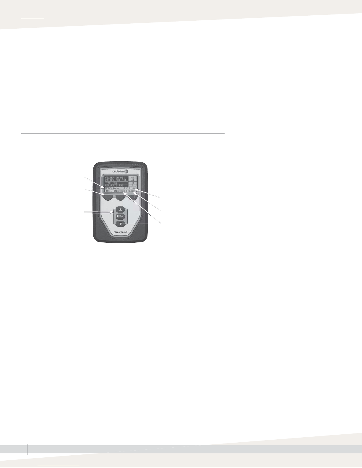
FIGURE 4-1: VAPOR-LOGIC KEYPAD/DISPLAY AND WEB INTERFACE
KEYPAD/DISPLAY
Mode
Softkeys
for direct menu access
Navigation buttons
for item selection
Tank status
System alarms
System messages
Static IP addresses
See the Vapor-logic Controller Installation and
Operation Manual shipped with the RO system
for more information about confi guring IP
addresses.
DRISTEEM RO 200 SYSTEM WATER TREATMENT SYSTEMS INSTALLATION, OPERATION, AND MAINTENANCE MANUAL
4
Page 9
Product overview
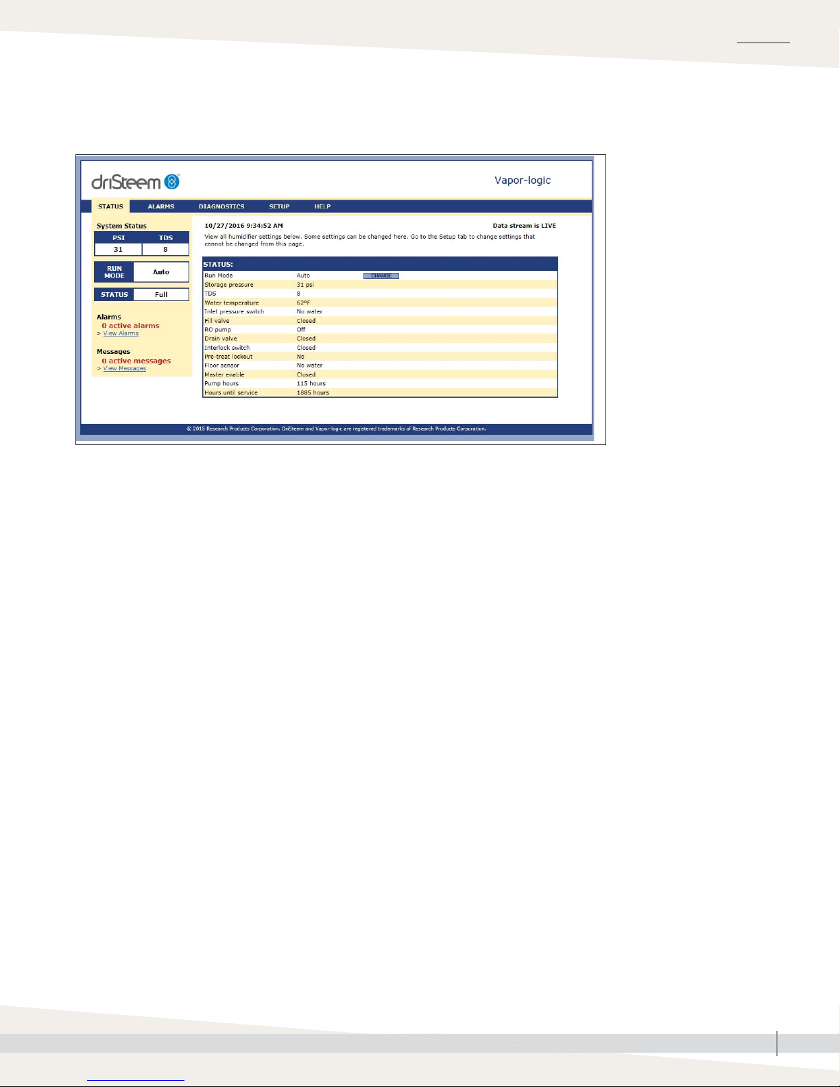
WEB INTERFACE
OVERVIEW
RO SUPPLY WATER REQUIREMENTS
Supply water quality is an important component
of DriSteem reverse osmosis system reliability and
maintenance.
Water hardness can increase the reverse osmosis system
maintenance requirements.
To maximize service life and minimize maintenance for
RO systems and downstream equipment, softened water is
required with all DriSteem RO systems.
DRISTEEM RO 200 SYSTEM WATER TREATMENT SYSTEMS INSTALLATION, OPERATION, AND MAINTENANCE MANUAL
5
Page 10
OVERVIEW
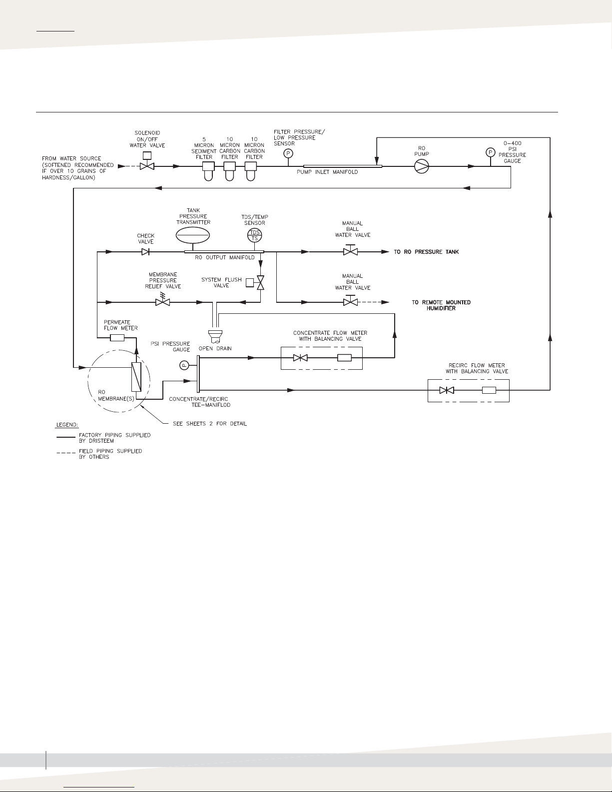
Flow schematic
FIGURE 6-1: FLOW SCHEMATIC
RO200-PIPING
DRISTEEM RO 200 SYSTEM WATER TREATMENT SYSTEMS INSTALLATION, OPERATION, AND MAINTENANCE MANUAL
6
Page 11
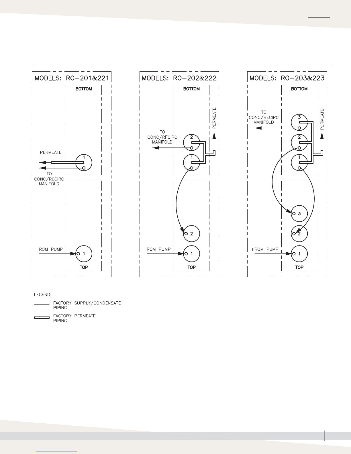
Flow schematic
FIGURE 7-1: FLOW SCHEMATIC
OVERVIEW
DRISTEEM RO 200 SYSTEM WATER TREATMENT SYSTEMS INSTALLATION, OPERATION, AND MAINTENANCE MANUAL
RO200-PIPING-1
7
Page 12

OVERVIEW
Component identifi cation
FIGURE 8-1: COMPONENT IDENTIFICATION
10
11
9
4
7
1
12
13
3
6
5
8
15
16
14
2
Table 8-1:
Component identification
Item Description
1 Vapor-logic keypad/display Power On/Off and status display
2 Inlet solenoid valve Normally closed. Opens when power is applied.
3 Filter pressure sensor
4 Sediment fi lter 5 micron sediment fi lter.
5 Carbon fi lter 10 micron extruded carbon cartridge to remove chlorine and reduce organics from the feed stream.
6 Low pressure sensor Shuts the system down if the inlet pressure is lower than 8 psi (adjustable).
7 High pressure pump and motor Rotary pump and motor to pressurize the incoming water.
8 Membrane modules RO membrane elements housed in stainless steel pressure tubes.
9 System pressure gauges Measure the system (feed) and concentrate (effl uent) pressure of the membrane modules.
10 Concentrate to drain control valve To adjust system pressure. Must not be completely closed when the system is in operation.
11 Concentrate recirc control valve To adjust and maintain adequate fl ow thru membranes
12 Permeate fl ow control valve Monitor permeate water fl ow.
13 TDS monitor Monitors the feed and permeate water quality.
14 Permeate check valve Prevents backfl ow into RO module.
15 Pipe drain Drain assembly. Run to a fl oor drain.
16 Vapor-logic control board The Vapor-logic control board is mounted inside the control cabinet.
Measure the feed and effl uent pressure of the cartridge fi lters. Pressure difference determines when
cartridge change out is required.
DRISTEEM RO 200 SYSTEM WATER TREATMENT SYSTEMS INSTALLATION, OPERATION, AND MAINTENANCE MANUAL
8
Page 13

Piping and instrumentation arrangement
FIGURE 9-1: FLOW SCHEMATIC WITH A CARTRIDGE DECHLORINATOR
INSTALLATION
OM-7905
DRISTEEM RO 200 SYSTEM WATER TREATMENT SYSTEMS INSTALLATION, OPERATION, AND MAINTENANCE MANUAL
9
Page 14

OPERATION
System operation
INITIAL SYSTEM START-UP
SYSTEM FLUSH
Direct permeate discharge to drain for fi rst 30 minutes of operation.
1. Connect the system to the appropriate electrical outlet, 110-120 VAC or
208-240 VAC 1 phase.
2. Ensure all plumbing connections are open to allow flow. Open the
concentrate valve (counterclockwise). Close the recirc valve (clockwise).
Ensure suffi cient pressure (40 psi recommended) is in feed line. If pressure
is less than 8 psi, the low pressure sensor will disallow start-up until
pressure is adequate.
3. Press the power button; the solenoid will open and the unit will start
operating.
4. After water is flowing from the concentrate line, adjust the concentrate
control valve to obtain designated flow for the specific model (see Table
3-2 on page 3).
5. If required, adjust recirc control valve to meet desired flow rates (see
Table 3-2 on page 3).
6. Allow the unit to run for 30 minutes to ensure proper flushing of system.
7. After the flush time is over, press the power button OFF.
8. Redirect the permeate line to the desired location.
NORMAL OPERATIONS
1. Turn the power back ON. After the pump starts, adjust the control valve to
the desired flow/pressure (not to exceed 150 psi).
FIGURE 10-1: CONTROL VALVES
CAUTION
To prevent concentrate from
precipitating and causing irreversible
fouling of the RO membrane, do not
operate the system with the control
valve completely closed.
2. The recirculation valve may now be adjusted to achieve desired
recirculation flow rate, ensuring concentrate flow rate is as specified.
SHUTDOWN
1. Press the power button to shut unit OFF. Close the isolation valve if it is
installed on the feed line.
CAUTION
Do not exceed recommended
maximum recovery.
2. If the unit is to be shut down for more than one week, a membrane
preservative should be used. To accomplish this, perform 30 second flush
using cartridge filter insert (see page 24 for more information). After
30 seconds, press the power button OFF, and close the concentrate valve.
This will hold the preservative in the pressure vessel.
3. When the system is restarted after an extended shutdown, follow initial
system start-up procedures.
DRISTEEM RO 200 SYSTEM WATER TREATMENT SYSTEMS INSTALLATION, OPERATION, AND MAINTENANCE MANUAL
10
Page 15

OPERATION
Start-up checklist
If an item in the Start-up checklist below does not apply to your system, skip to the next item and continue the process.
☐ Read this manual and all other information that was provided with your system.
☐ Verify that all fi eld wiring is done according to the instructions in this manual and in the unit wiring diagram.
☐ Confi rm that proper grounding and an approved earth ground are provided.
☐ Confi rm that the keypad/display is mounted with its modular cable routed away from high-voltage circuits and
connected to the Display connector on the Vapor-logic board.
☐ Install cartridge fi lter and check for leaks.
☐ Precharge pressurized RO storage tank to 28 psi (195 kPa).
Note: This precharge pressure is for pressurized RO storage tank cut-in and cut-out switch points at 30 and 50 psi
(210 and 345 kPa) respectively.
☐ Turn on the water supply, and confi rm there are no leaks.
☐ Turn on power to the unit, and confi rm the Main menu is displayed on the keypad/display. The display may take
several seconds to appear as the controller powers up.
☐ Confi rm in the Main Menu that the mode is “Auto” and that status is “Idle.”
☐ When “Idle” appears in main menu, confi rm that the inlet pressure is at least 40 psi (276 kPa) on the display.
☐ With suffi cient water available, the system in Auto mode, and the storage tank pressure less than 30 psi (210 kPa),
verify that the pump is activated.
☐ Set perm fl ow and recirc fl ow meter to desired setting.
☐ If you experience diffi culties, have the keypad/display information available along with the serial number and unit
Model, and call DriSteem Technical Support at 800-328-4447.
Note: Instructions on how to properly care for the freeze protect chemical that is shipped with the system is available
on the SDS sheet at www.dristeem.com.
☐ Inspect to insure that no fl exible plumbing lines have been kinked or damaged during installation.
WARNING
Tipping hazard
Before installing the 200 series
reverse-osmosis system, use
supplied leg brackets or lag points
to permanently fi x the system to
the fl oor and/or adjacent building
structure. Failure to install according
to instructions can result in serious
injury or death. See page 10 for
instructions.
DRISTEEM RO 200 SYSTEM WATER TREATMENT SYSTEMS INSTALLATION, OPERATION, AND MAINTENANCE MANUAL
11
Page 16

OPERATION
Start-up
START-UP PROCEDURE
Check component installation per the layout shown in Figure 6-1
(depending on your model). After all components are installed and connected
properly:
1. Perform all applicable “Start-up checklist” items on Page 11.
2. Read and follow instructions in the “Operation” section of Vapor-logic
Installation and Operation Manual.
Note: During start-up, do not leave the system unattended.
TEST OPERATION
Using the keypad/display or web interface, place pump station in Auto mode.
Perform the following procedure:
1. If the system has a full RO holding tank, create a call for water by draining
water from the tank until the pressure falls below 30 psi (210 kPa).
2. Monitor system performance, and watch for leaks.
3. If a leak is found:
a. Remove demand signal, and put the system in Standby mode.
b. Tighten any loose connections.
c. Return system to Auto mode.
d. If a leak persists, replace tubing or fi tting that is leaking.
Important
If the system is not in operation within six
months of shipment, it is strongly recommended
to use an organic cleaning cartridge prior
to performing the start-up checklist to ensure
proper operation. See page 11 for
information and part number.
CAUTION
If the pump chatters loudly, it is
starving for water (cavitating). Turn the
unit OFF immediately to prevent pump
damage. Correct the low pressure
condition before proceeding.
FIGURE 12-1: SOLENOID VALVE INLET
4. Leave system in Auto mode. It will automatically refill the RO holding tank
when pressure falls below 30 psi (210 kPa).
INITIAL SYSTEM START-UP
1. Close the manual valves to both the RO holding tank and all downstream
equipment. Open the manual valve leading to the drain.
2. Open the feed water supply valve.
3. Open the concentrate control valve fully counterclockwise. Close the
recirculation valve.
4. Put the system into 'Auto' mode. Note inlet water pressure must be at least
40 psi (276 kPa).
5. If incoming pressure is too high, an inlet pressure regulator (not included)
may be installed. This should be set at 40 psi (276 kPa).
6. Some fittings may have loosened during shipment. Check for leaks at all
tube fittings and threaded joints.
7. Allow the unit to run for at least 30 minutes to flush the preservative
solution from the system.
CAUTION
Pump and system performance will be
adversely affected if the feed/suction
line is restricted.
DRISTEEM RO 200 SYSTEM WATER TREATMENT SYSTEMS INSTALLATION, OPERATION, AND MAINTENANCE MANUAL
12
Page 17

Start-up
OPERATION
1. Once the preservative solution has been flushed from the system, shut
down the system by putting the system into 'Standby' mode on the Vaporlogic keypad and close the manual valve going to the drain. Open the
manual valves to both the RO storage tank and downstream equipment.
2. Run a ¾" MNPT from the stand pipe drain to an open drain.
3. Put the system back into 'Auto' mode.
4. Adjust the throttle valve to get the specified permeate flow (if applicable).
5. Adjust the concentrate valve and recirculation valve until the specified
permeate flow and recirculation flow are obtained. It may be necessary to
readjust the throttle valve. See Table 3-1.
6. Test the operation of a low pressure sensor by slowly closing the inlet
water supply valve. The unit should shut off after a short 5 second time
delay.
7. Once all the desired flows are set, allow the system to run for
approximately 30 minutes. Then record the performance information using
the system operation data log on page 26. The values recorded at
startup will be important for determining system performance at a later
date.
OPERATING DO'S AND DON'T'S
CAUTION
Do not operate the system with the
control valve closed.
Important:
By setting the feed pressure as low as possible
to meet the application requirement, the
service life of the pump and RO elements
will be optimized. The system should be run
continuously when possible, rather than go
through frequent start/stop cycles.
CAUTION
Damage to pump
Do not close the valve. Do not operate
the pump below minimum combined
fl ow rate (permeate + concentrate +
recirculating).
DO
1. Change the cartridge filters regularly
2. Monitor the system and keep a log daily
3. Run the system, as much as possible, on a continuous basis.
4. Adjust the system recovery to the recommended value
DON'T
1. Permit chlorine in the feed water.
2. Shut down the system for extended periods. If system will be down for
more than one week, treat the system with a membrane preservative. See
page 20 for instructions.
3. Close the throttle valve completely.
4. Operate the system with insufficient feed flow.
CAUTION
Confi rm all lines are connected before
plugging in unit power.
DRISTEEM RO 200 SYSTEM WATER TREATMENT SYSTEMS INSTALLATION, OPERATION, AND MAINTENANCE MANUAL
13
Page 18

OPERATION
Vapor-logic keypad/display
FIGURE 14-1: USING THE VAPOR-LOGIC KEYPAD/DISPLAY
Typical Home screen
Tank pressure/status
Change Mode from the Home
screen by pressing the Up or
Down arrow keys until Mode
is highlighted, press Enter,
press Up or Down arrow keys
to change, press Enter to
confi rm
Total dissolved solids (TDS)
Status
Press Main softkey for
Main menu; other softkey
functions vary by screen
Press Up or Down
arrow to move through
menus and screens
Alarm
label flashes
when there is a
system alarm
Message
label fl ashes
when there is a
system message
Press
Enter
to select or
confi rm
DRISTEEM RO 200 SYSTEM WATER TREATMENT SYSTEMS INSTALLATION, OPERATION, AND MAINTENANCE MANUAL
14
Page 19

Keypad/display Home screens,Test outputs, Test run
OPERATION
Vapor-logic returns to the Home screen on the keypad/display after a userdefi ned period of idleness. The Home screen displays the items most frequently
viewed.
CHANGING MODE
Mode can be changed from the Home screen. Press the Up or Down arrow
key until the Mode is highlighted, press Enter, press Up or Down arrow key to
change value, press Enter to confi rm. All other parameters shown on the Home
screen are for viewing only and cannot be changed. Go to the Setup menu to
change these items.
CONTROLLER DISPLAY ACTIVITY DEFINITIONS
(Figure 15-1)
RO fl ush: System is performing an RO fl ush.
Idle: No demand, or an active alarm is preventing operation.
Filling: System is supplying high-pressure water to meet demand.
Full: Storage tank is full, system not running.
TEST OUTPUTS
When completing an installation or repair, cycle all outputs, to verify
operation. Go to the test outputs section of the Diagnostics menu and scroll
through each connected output to verify operation. During testing, the unit
mode changes to Standby and the tank status changes to Test.
FIGURE 15-1: RO STATION KEYPAD/
DISPLAY HOME SCREEN
TEST RUN
Vapor-logic has a test run capability to confi rm system functionality. This
capability allows a technician to simulate a demand when there isn’t one (such
as when performing routine maintenance). To confi rm functionality, go to the
test run section of the Diagnostics menu. Set system demand percent and set
test run time duration. During testing, the unit mode changes to Standby and
the tank status changes to Test.
DRISTEEM RO 200 SYSTEM WATER TREATMENT SYSTEMS INSTALLATION, OPERATION, AND MAINTENANCE MANUAL
15
Page 20

OPERATION
Status screen
Table 16-1:
Status screen
Note: Your system might not have all of the items listed in this table.
Menu
item
Run mode Standby -- -- --
TDS -- 0 9999 ppm
TDS set point 50 0 100 ppm
Water temperature
Safety interlock Closed Open Closed --
Inlet pressure sensor -- No water Water --
Storage pressure -- 0 100 psi Storage tank pressure.
Pump hours -- 0 100,000 Hours
Default
value
Minimum
value
-- -50 250 °F Sensor range
-- -46 121 °C Sensor range
Maximum
value
Units Notes
Operating mode of unit. Choose from Auto, Standby, or Drain.
• In Auto mode, the unit operates normally. All unit components are
monitored and controlled. If there is a call for cooling/humidifi cation, the
system reacts.
• In Standby mode, the unit is offl ine. All control inputs appear but are
not acted upon; however, if the water temperature falls below the freeze
protect set point, the drain valve opens.
• In Drain mode, the RO Flush valve opens, the RO tank drains, and the RO
system begins making RO water. All unit operation is suspended, and the
RO Flush valve remains open until the model specifi c RO fl ush time is met
the unit is taken out of RO fl ush mode, or the RO tank is drained.
• See the Diagnostics section for information about Test outputs and Test run
modes.
Table 16-2:
Setup screen
Note: Your system might not have all of the items listed in this table.
Menu
item
Membrane fl ush 300 0 300 seconds
System fl ush 72 1 336 hours
Default
value
Minimum
value
Maximum
value
Units Notes
Table 16-3:
TDS setting
Note: Your system might not have all of the items listed in this table.
Menu
item
High TDS causes Alarm Message Alarm --
TDS setpoint 50 25 100 --
Default
value
Minimum
value
Maximum
value
Units Notes
DRISTEEM RO 200 SYSTEM WATER TREATMENT SYSTEMS INSTALLATION, OPERATION, AND MAINTENANCE MANUAL
16
Page 21

OPERATION
Diagnostics and Alarms
Table 17-1:
Diagnostics menu
Note: Your system might not have all of the items listed in this table.
Message Description Auto-clear?
Pretreat lockout Softener or other pretreatment is preventing the RO station from operation. Yes
No master enable Master enable for the system is open. Yes
Excessive TDS
Service unit Regularly scheduled unit servicing is due. No
I-lock open Interlock safety switch is open. Yes
Notes:
• The Messages Log displays message name, date and time of occurrence, plus “Active,” “Cleared” or “Auto-cleared.”
• Active messages display fi rst in the Messages Log, followed by cleared messages (auto-cleared and/or manually-cleared) listed in order of
occurrence.
• The Messages Log displays a maximum of 10 messages. Cleared messages leave the log fi rst.
• If a message event occurs and is not manually or auto cleared during unit operation, the message will stay there until there is demand and the
unit is running.
TDS measurement during RO production exceeds the TDS set point.
The system will continue to operate but the membranes may need to be replaced.
Yes
Table 17-2:
Alarm menu
Alarm level Description Auto-clear?
Temp sensor fault Water temperature/TDS sensor reading is out of range. Yes
Low inlet pressure* Water pressure at RO inlet is less than 10 psi. Yes
High storage
pressure
Floor sensor active Optional fl ooded fl oor pan circuit is active. No
Storage pressure
sensor
Excessive TDS
Notes:
• See the "troubleshooting" section in the Vapor-logic Installation and Operation Manual for alarm possible causes and recommended actions.
• The Alarms Log displays alarm name, date, and time of occurrence, plus "Active," "Cleared," or "Auto-cleared."
• Active alarms display fi rst in the Alarms Log, followed by cleared alarms (auto-cleared and/or manually-cleared) listed in order of occurrence.
• The Alarms Log displays maximum 30 alarms. Cleared alarms leave the log fi rst.
• If an alarm event occurs and is not manually cleared or auto-cleared during unit operation, the alarm will remain until there is demand and the
unit is running.
* Pressure alarm will occur if inlet pressure falls below 5 psi. Alarm will self-clear when RO system supply pressure is above 10 psi for at least 10
consecutive seconds. A pressure fault can be manually cleared at any time. System will try to operate every 10 consecutive seconds per hour up to
72 hours while in low pressure alarm condition.
Tank storage pressure has exceeded 60 psi. Yes
Pressure sensor reading is out of range. Yes
TDS measurement during RO production exceeds the TDS set point.
The system will continue to operate but the membranes may need to be replaced.
No
DRISTEEM RO 200 SYSTEM WATER TREATMENT SYSTEMS INSTALLATION, OPERATION, AND MAINTENANCE MANUAL
17
Page 22

OPERATION
Modbus, BACnet, LonTalk interoperability
Table 18-1:
Interoperability vaiable and object names
Variable name and
BACnet object name
Read-only analog variables
Storage_pressure RO IR-1 AI-1 nvoStoragePress Storage pressure psi bar 0 100
Pump_1_hour RO IR-2 AI-2 nvoPumpHours Hours of operation hours hours 0 100000
Water_temp RO IR-3 AI-3 nvoWaterTemp
TDS RO IR-4 AI-4 nvoTDS TDS — — 0 9999
Set Variables
Run_mode
TDS_setpoint RW HR-2 AV-1 nviTDS_SP TDS set point — — 0 75
Read-only digital I/O
Safety_interlock RO DI-1 BI-01 nvol-LockSW
Pretreat_lockout_sw RO DI-2 BI-02 nvoPreTreatSW
Floor_water_sw RO DI-3 BI-03 nvoFloorSW
Inlet_pressure_sw RO DI-4 BI-04 nvoInletPressSW
Master_enable_sw RO DI-5 BI-05 nvoMasterEnabSW
Supply_valve RO DI-6 BO-01 nvoSupplyValve
Drain_valve RO DI-7 BO-02 nvoDrainValve
RO_pump RO DI-8 BO-03 nvoROpump 0=Off; 1=On ————
Notes:
1. Modbus Input Registers (IR1-IR4) 16 bit read only
Modbus Holding Registers (HR1-HR2) 16 bit read/write
Modbus Discrete Input Registers (DI1-DI8) single bit read only
Modbus Coil Registers (DV1-DV8) single bit read/write
2. nvi LonTalk SNVTs are write-only; nvo are read-only
Read Only
(RO) or
Read Write
(RW)
Write HR-1 MSV-01 nviRunMode
Read HR-1 MSV-01 nvoRunMode
Modbus
register
number*
BACnet
Object
Type and
Instance
LonTalk variable
names**
Description Units Range
I-P units SI units I-P units SI units
Temperature of RO
water
Mode of the unit
or system. The
defi ned options
are:
1=Auto;
2=Local standby;
3=System standby;
4=Manual drain;
5=Test outputs;
6=Test run
Mode of the unit
or system. The
defi ned options
are:
1=Auto;
2=Local standby;
3=System standby;
4=Manual drain;
5=Test outputs;
6=Test run
0=Open;
1=Closed
0=Open;
1=Closed
0=Water;
1=No Water
0=No Water;
1=Water
0=Open;
1=Closed
0=Open;
1=Closed
0=Open;
1=Closed
F C -50 to 250 -46 to 121
— — 1 to 4 1 to 4
1 to 6 1 to 6
————
————
————
————
————
————
————
DRISTEEM RO 200 SYSTEM WATER TREATMENT SYSTEMS INSTALLATION, OPERATION, AND MAINTENANCE MANUAL
18
Page 23

OPERATION
Modbus, BACnet, LonTalk interoperability
Table 18-1:
Interoperability vaiable and object names
Variable name and
BACnet object name
Faults and Alarms
ProgOutput1_status RW DV--01 BV-01 nvoDryConStat1 NO or NC output — — — —
ProgOutput2_status RW DV-02 BV-02 nvoDryConStat2 No or NC output — — — —
Active_manually_
cleared_alarm_exists
Clear_all_faults RW DV-04 BV-04 nviClrAllFault
Alarm_temp_sensor_
failed
Alarm_low_inlet_
pressure
Alarm_excessive_
storage_pressure
Alarm_fl oor_water_
sensor_activated
Alarm_pressure_sensor_
out_of_range
Alarm_excessive_TDS_
during_fi ll
Message_pretreat_
lockout_active
Message_excessive_
TDS_during_fi ll
Message_service_unit RW DV-13 BV-13 nvoMsgSrviceUnt
Message_interlock_open RW DV-14 BV-14 nvoMsgllockOpen
Message_master_
enable_open
Notes:
1. Modbus Input Registers (IR1-IR11) 16 bit read only
Modbus Holding Registers (HR1-HR10) 16 bit read/write
Modbus Discrete Input Registers (DI1-DI9) single bit read only
Modbus Coil Registers (DV1-DV15) single bit read/write
2. nvi LonTalk SNVTs are write-only; nvo are read-only
Read Only
(RO) or
Read Write
(RW)
RW DV-03 BV-03 nvoAlarmManCl
RW DV-05 BV-05 nvoAlmTempSense
RW DV-06 BV-06 nvoAlmInPress
RW DV-07 BV-07 nvoAlmOutPress
RW DV-08 BV-08 nvoAlmFloorWet
RW DV-09 BV-09 nvoAlmPrSensOOR
RW DV-10 BV-10 nvoAlmExcessTDS
RW DV-11 BV-11 nvoMsgPretreatL
RW DV-12 BV-12 nvoMsgExcessTDS
RW DV-15 BV-15 nvoMsgNoMastEnb
Modbus
register
number*
BACnet
Object
Type and
Instance
LonTalk variable
names**
Description Units Range
I-P units SI units I-P units SI units
Flags all manually
cleared alarms
When set will clear
all active faults
See Table 17-2:
Alarm menu
See Table 17-2:
Alarm menu
See Table 17-2:
Alarm menu
See Table 17-2:
Alarm menu
See Table 17-2:
Alarm menu
See Table 17-2:
Alarm menu
See Table 17-1:
Diagnostics menu
See Table 17-1:
Diagnostics menu
See Table 17-1:
Diagnostics menu
See Table 17-1:
Diagnostics menu
See Table 17-1:
Diagnostics menu
——— —
——— —
——— —
——— —
——— —
——— —
——— —
——— —
——— —
——— —
——— —
——— —
——— —
DRISTEEM RO 200 SYSTEM WATER TREATMENT SYSTEMS INSTALLATION, OPERATION, AND MAINTENANCE MANUAL
19
Page 24

MAINTENANCE
Maintenance information
MAINTENANCE TIPS
Maintain proper operating conditions:
• Do not exceed 90 psi (620 kPa) on the fi lter inlet pressure reading.
• Do not over use recirculation fl ow. This can cause premature scaling of the
membrane. A proper concentrate fl ow is required for a long membrane life.
See page 3 for maximum recirculation fl ow.
• To ensure no chlorine reaches the RO membranes, test the water from your
dechlorinator periodically for chlorine break through.
WHEN TO CHANGE SEDIMENT AND CARBON FILTERS
Sediment and carbon fi lters should be changed regularly to maintain proper
pressure and fl ow and water quality.
Change the carbon fi lter when chlorine from supply water starts to pass
through. The carbon fi lter removes chlorine. Check regularly for chlorine pass
through. To check for chlorine, obtain a water sample from the concentrate
drain line and test the water. If chlorine is present, change the carbon fi lter and
record the interval to estimate the next carbon fi lter change.
Change the sediment fi lter when the difference between fi lter inlet pressure and
fi lter outlet pressure increases by 10 psi over the initial pressure difference.
For example, if initial readings are 60 psi in and 58 psi out, the difference is
2 psi. Therefore, when that difference reaches 12 psi, it is time to replace the
sediment and carbon cartridges.
FIGURE 20-1: SEDIMENT FILTER
DriSteem replacement part
• 2.5" x 10" - (part number: 550030-002)
FIGURE 20-2: CARBON FILTER
CHANGING CARTRIDGE FILTERS
1. Put the system into 'Standby' mode and shut down the RO system.
2. Close inlet supply valve.
3. Un-assemble the filter housing (twist the sump counter-clockwise).
4. Remove and inspect the cartridge. Replace as needed.
5. Before replacing housing, insure that O-ring seal is lubed and placed in
groove of housing. Inspect seal and replace as needed.
6. Assemble housing (turn the sump clockwise into the cap until tight).
Important: Verify regularly that water processing equipment is operating
correctly. The presence of chlorides in improperly process deionized water will
eventually cause pitting and failure of the equipment the RO system is servicing
and its components. Damage cause by chloride corrosion is not covered by
your DriSteem warranty. The RO system has an automatic drain sequence
(ADS) set based on default supply concentration of 20 ppm. Adjust ADS to
actual supply water connection.
DriSteem replacement part
• 2.5" x 10" - (part number: 550030-003)
CAUTION
Chlorine can damage the membrane.
A carbon pre-fi lter is installed to
remove chlorine from fee water. Care
must be taken to change this carbon
fi lter as needed to accomplish effective
chlorine removal. Excessive chlorine
in feed stream may require additional
pre-fi ltration. The feed stream should
be tested for chlorine at least once
a week. Always follow proper
maintenance procedures.
DRISTEEM RO 200 SYSTEM WATER TREATMENT SYSTEMS INSTALLATION, OPERATION, AND MAINTENANCE MANUAL
20
Page 25

Maintenance continued
MAINTENANCE
WHEN TO CLEAN OR REPLACE MEMBRANES
In normal operation, the membrane in reverse osmosis elements can become
fouled by mineral scale, biological matter, and grime. These deposits build
up during operation until it causes loss in water output or loss of salt rejection,
or both. Elements should be cleaned or replaced whenever the water output
rate drops by 10 percent from its initial fl ow rate (the fl ow rate established
during the fi rst 24 to 48 hours of operation) or when TDS in the product water
(permeate) rises above 50. This is indicated through a message on the Vaporlogic controller (above 75 will alarm).
It should be noted that the water output rate will drop if feed water temperature
decreases (about 1.5% per °F). This is normal and does not indicate membrane
fouling. A malfunction in the pretreatment, pressure control or pump can cause
a drop in feed water delivery pressure, feed water fl ow, product water output,
or an increase in salt passage. If such adjustments are needed, the element
may not require cleaning.
REPLACING MEMBRANES
TOOLS
• Rubber mallet
• Flat blade screwdriver
• Open end wrench, ⅞ inch
• Safety glasses
FIGURE 21-1: PRE-FILTER
1
1. Sediment filter:
Removes sediments and particles down
to 5 micron size.
2. Carbon filter:
Primarily to remove chlorine; also
removes organics and sediments down
to 10 microns.
2
2
PROCEDURE
1. Turn OFF the RO system.
2. Relieve pressure on the membrane by opening the supply valve.
3. Remove all lines from the top of the pressure vessel(s). Make sure the
fittings are marked so the fittings go back to the correct locations after
replacing.
Note: Membranes on RO system are removed and inserted from the top.
4. Remove end plugs by pulling carefully. See Figure 21-2.
FIGURE 21-2: DRISTEEM REVERSE
OSMOSIS MEMBRANES
DRISTEEM RO 200 SYSTEM WATER TREATMENT SYSTEMS INSTALLATION, OPERATION, AND MAINTENANCE MANUAL
21
Page 26

MAINTENANCE
Maintenance continued
MEMBRANE CLEANING IN THE RO SYSTEM
Membrane cleaning cartridges:
• Clean membranes without having to remove them from the RO system
• Reduce downtime
• Maintain the system performance at a higher level
• Prolong membrane life by regular use of cleaning cartridges
HOW DOES IT WORK?
NOTE: Clean monthly to obtain optimum results.
1. Exchange the system's sediment filter with a cleaning cartridge.
2. Follow the instructions.
3. Restart the system.
4. Repeat the process if required.
SCALE CLEANING CARTRIDGE
The scale cleaning cartridge is for removal of mineral scale and build-up.
CLEANING PROCEDURE
1. Put the system into 'Standby' mode and shutdown the RO system.
2. Disconnect permeate line and divert to drain before any cleaning
cartridge is installed.
3. Remove the sediment filter from the pre-filter housing.
FIGURE 22-1: 10 INCH SCALE CLEANING
CARTRIDGE
DriSteem replacement part
• 2.5" x 10" - (part number: 550045-401)
CAUTION
Handle all chemicals with care. Wear
protective clothing and eye protection.
4. Replace the sediment filter with the cleaning cartridge and assemble into
the filter housing.
5. Turn the system ON and put into 'Auto' mode. After 30-40 seconds, shut
down the system.
OPTIONAL: Instead of time, use one of the following criteria:
a. Run the system until the pH of the concentrate is almost the same as the
cleaning solution (pH=3)
b. Permeate rate for the system drops to a very low value.
6. Let the membrane(s) soak in the cleaning solution overnight.
7. Remove the empty cleaning cartridge and replace it with the original filter.
8. Restart the system. Direct the permeate to drain for five minutes.
9. Go back to normal operations.
CAUTION
The system must be fl ushed thoroughly
between acid and alkaline cleaning.
DRISTEEM RO 200 SYSTEM WATER TREATMENT SYSTEMS INSTALLATION, OPERATION, AND MAINTENANCE MANUAL
22
Page 27

Maintenance continued
MAINTENANCE
ORGANIC CLEANING CARTRIDGE
The organic cleaning cartridge is for removal of organics/fouling.
CLEANING PROCEDURE
1. Put the system into 'Standby' mode and shutdown the RO system.
2. Disconnect permeate line and divert permeate to drain during cleaning.
3. Remove the sediment filter from the filter housing.
4. Replace the sediment filter with the cleaning cartridge and assemble into
the filter housing.
5. Turn the system ON. After 30-40 seconds, shut down the RO system.
OPTIONAL: Instead of time, use one of the following criteria:
a. Run the system until the pH of the concentrate is almost the same as the
cleaning solution (pH=10-12)
b. Permeate rate for the system drops to a very low value.
6. Let the membrane(s) soak in the cleaning solution overnight.
7. Remove the empty cleaning cartridge and replace it with the original filter.
8. Restart the system. Direct the permeate to drain for five minutes.
9. Go back to normal operations.
FIGURE 23-1: 10 INCH ORGANIC
CLEANING CARTRIDGE
DriSteem replacement part
• 2.5" x 10" - (part number: 550045-501)
CAUTION
Handle all chemicals with care. Wear
protective clothing and eye protection.
CAUTION
The system must be fl ushed thoroughly
between acid and alkaline cleaning.
DRISTEEM RO 200 SYSTEM WATER TREATMENT SYSTEMS INSTALLATION, OPERATION, AND MAINTENANCE MANUAL
23
Page 28

MAINTENANCE
Storage
To prevent bacterial growth and help maintain fl ux, it is recommended that
elements be immersed in a preservative solution if the system will be OFF for
more than one week.
MEMBRANE PRESERVATIVE CARTRIDGE
PRESERVING PROCEDURE
1. Shut down the RO system.
2. Disconnect the permeate line and direct permeate to drain during
cleaning/preserving.
3. Remove the 5M filter cartridge from the pre-filter housing.
4. Replace the filter cartridge with the preservative cartridge and assemble
into the filter housing.
5. Turn the system ON. After 30-40 seconds, shut down the system.
6. Drain the system of the permeate solution as much as possible by opening
a valve/fitting at a low point in the system.
7. Close OFF the inlet and outlet to the membrane/system.
FLUSHING OUT PRESERVATIVE/RESTART PROCEDURE
8. Open valves and put the system back in the position it was before
preserving.
FIGURE 24-1: 10 INCH BIG BLUE
CLEANING CARTRIDGE
DriSteem replacement part
• 2.5" x 10" - (part number: 550045-802)
9. Remove the empty preservative cartridge and replace it with a new
cartridge filter.
10. Restart the system. Direct permeate to drain for 15-30 minutes.
11. Go back to normal operation.
DRISTEEM RO 200 SYSTEM WATER TREATMENT SYSTEMS INSTALLATION, OPERATION, AND MAINTENANCE MANUAL
24
Page 29

System monitoring and record keeping
The system should be monitored and all pertinent data recorded on a daily
basis. This includes cartridge fi lter pressure in/out, system pressure in/out,
fl ow and water quality (TDS) in/out. Data is needed to determine operating
effi ciency and for performing system maintenance. The latter includes cleaning
of the membranes, adjusting the operating conditions as well as replacement
of cartridge fi lters and RO membranes.
Table 25-1:
Troubleshooting
Issue Possible Cause Solution
Inlet pressure low* Low supply pressure Correct incoming supply pressure
MAINTENANCE
Cartridge fi lters plugged Change fi lters
Solenoid valve malfunction Replace solenoid valve and/or coil
Permeate fl ow low Low water temperature Adjust water temperature
Low system pressure Adjust concentrate control valve
Membranes fouled Clean membranes
Pump noisy Low inlet fl ow See "Inlet pressure low"
Permeate quality poor Low inlet fl ow Adjust concentrate control valve
Low system pressure See "Inlet pressure low"
Recovery too high Reduce recirculation control valve
Membranes fouled Clean membranes
Membranes damaged Replace membranes
* Pressure alarm will occur if inlet pressure falls below 5 psi. Alarm will self-clear when RO system supply pressure is above 10 psi for at least 10
consecutive seconds. A pressure fault can be manually cleared at any time. System will try to operate every 10 consecutive seconds per hour up to
72 hours while in low pressure alarm condition.
DRISTEEM RO 200 SYSTEM WATER TREATMENT SYSTEMS INSTALLATION, OPERATION, AND MAINTENANCE MANUAL
25
Page 30

MAINTENANCE
System operating log
Table 26-1:
System operating log
Date
Time
Chlorine
Cartridge in psi
Cartridge out psi
Water temperature
TDS in
TDS out
System psi
Concentrate psi
Cartridge fi lter change
Membrane change
Recorded by
Notes
_________________________________________________________________________________________________________________________________
_________________________________________________________________________________________________________________________________
_________________________________________________________________________________________________________________________________
_________________________________________________________________________________________________________________________________
_________________________________________________________________________________________________________________________________
_________________________________________________________________________________________________________________________________
_________________________________________________________________________________________________________________________________
_________________________________________________________________________________________________________________________________
DRISTEEM RO 200 SYSTEM WATER TREATMENT SYSTEMS INSTALLATION, OPERATION, AND MAINTENANCE MANUAL
26
Page 31

MAINTENANCE
Water quality test strips
WATER QUALITY TEST STRIPS SAMPLE PACK
• Carbon fi lters in the RO-200 water treatment system should be changed regularly to maintain proper pressure and
fl ow and water quality.
• The carbon fi lter removes chlorine. Change the carbon fi lter when chlorine from supply water starts to pass through.
Check regularly for chlorine pass through.
• To check for chlorine, obtain a water sample from the concentrate drain line and test the water. If chlorine is
present, change the carbon fi lter and record the interval to estimate the next carbon fi lter change.
• For best results, test water chlorine every two weeks.
• To order more Water Quality Test Strips, contact your local
DriSteem rep, or call 1-800-328-4447.
Total Chlorine ppm - end pad
0 0.5 1.0 2.0 4.0 10.0
Free Chlorine ppm
0 0.5 1.0 2.0 4.0 10.0
Total Hardness (CaCo3) grains per gallon
0 1.5 3 7 15 25
0 25 50 120 250 425
ppm
Total Alkalinity ppm (CaCo3)
0 40 80 120 180 240
pH - pad nearest handle
6.2 6.8 7.2 7.8 8.4
DIRECTIONS:
1. Dip entire strip into water for 1 second (or
pass under water stream), remove. Do not
shake excess water from the test strip. Hold
the strip for 30 seconds.
2. Compare TOTAL HARDNESS, TOTAL
ALKALINITY and pH pads to color chart to the
left.
3. Dip strip into the water again and move back
and forth for 30 seconds (or hold two chlorine
pads under water stream for 10 seconds).
4. Compare CHLORINE pads to color chart to
the left.
5. Track results in the chart below.
6. Change the carbon cartridge filter once
chlorine is detected in the concentrate water
of the RO 200 water treatment system (see
page 20).
Table 27-1:
Water quality test log
Date tested Total chlorine ppm Free chlorine ppm Total hardness Total alkalinity pH
Week 1 _________
Week 3 _________
Week 5 _________
Week 7 _________
Week 9 _________
Week 11 _________
DRISTEEM RO 200 SYSTEM WATER TREATMENT SYSTEMS INSTALLATION, OPERATION, AND MAINTENANCE MANUAL
27
Page 32

REPLACEMENT PARTS
RO system (Models 201, 202, and 203)
FIGURE 28-1: RO 200 SYSTEM REPLACEMENT PARTS
DRISTEEM RO 200 SYSTEM WATER TREATMENT SYSTEMS INSTALLATION, OPERATION, AND MAINTENANCE MANUAL
28
OM-7871
Exploded view of the each unique
replacement part for the RO 200
system.
Page 33

RO system (Models 201, 202, and 203)
Table 29-1:
RO system replacements parts
No. Description Qty. Part No.
1 PUMP MOTOR 1/3 HP 100-120/200-240V 1 400292-001
REPLACEMENT PARTS
2
3 GAUGE LIQUID FILLED 400 PSI PNL MNT KIT 2 260004-400
4 METER 2GPM FLOW W/NEEDLE VALVE 1/4" FNPT 2 501907-402
5 METER 2GPM FLOW 1/4" FNPT 1 501907-302
6 SEDIMENT FILTER 2.5" X 10" 5 MICRON 1 550030-002
7 CARBON FILTER 2.5" X 10" 10 MICRON 2 550030-003
8 HOUSING FILTER 2.5" X 10" 3 550030-001
9 MANIFOLD ASSY OUTPUT RO-200 STAND ALONE 1 187714-002
10 MEMBRANE RO 2.5" X 21" EXTRA LOW ENERGY VARIES 550035-025
11 MEMBRANE VESSEL ASSY 2.5" X 23-5/16" VARIES 550038-025
12 TANK WATER PRESSURIZED 4.4 GAL 1 550029-004
13 DRAIN ASSY RO-200 1 165103-011
14 VALVE 1/2" SOLENOID TWO-WAY N.C. 3.35 CV 1 505107-050
* Specify RO system model and serial numbers when ordering.
PUMP ROTARY VANE BRASS 90 GPH 1 400294-001
PUMP ROTARY VANE BRASS 105 GPH 1 400294-002
DRISTEEM RO 200 SYSTEM WATER TREATMENT SYSTEMS INSTALLATION, OPERATION, AND MAINTENANCE MANUAL
29
Page 34

REPLACEMENT PARTS
Subpanel
FIGURE 30-1: CONTROL CABINET ASSY RO-200
OM-7939
Table 30-1:
Control cabinet assy RO-200
No. Description Qty. Part No. No. Description Qty. Part No.
1 Main controller VL6 1 408496-006 9 Terminal DIN rail 20A center 1 408252-001
Module LON protocol
2
(LON option only)
3 Resistor 1.2K OHM through hole 1 408995-008 11 Contactor 35A SIEMENS 1 407010-001
4 Bushing 7/8" shutter HEYCO 1 407129 12 Display VL w/o back Vapor-logic 1 408495-002
5 Lug medium 1 409250-027 13 Case rear display Vapor-logic 1 408495-003
6 Terminal block 3 pole pressure contact 1 408300-002 14 Wire data cable 27" RJ-12 1 408490-014
Transformer 120/208/240/480V TO
7
24VAC 75V
8 Terminal DIN rail end cap 1 408252-005 16 Plug 3 circuit vertical euro molex 1 406246-003
1 408642 10 Terminal DIN rail end 1 408252-006
1 408965-001 15 Mount wallplate wallphone SST 1 408490-021
17 Plug 4 circuit vertical euro molex 1 406246-004
DRISTEEM RO 200 SYSTEM WATER TREATMENT SYSTEMS INSTALLATION, OPERATION, AND MAINTENANCE MANUAL
30
Page 35

Notes
DRISTEEM RO 200 SYSTEM WATER TREATMENT SYSTEMS INSTALLATION, OPERATION, AND MAINTENANCE MANUAL
31
Page 36

W
ARRANTY
Expect quality from the industry leader
Since 1965, DriSteem has led the industry
with innovative methods for humidifying and
cooling air with precise control. Our focus on
ease of ownership is evident in the design of
our Water Treatment Systems, which feature
low maintenance and comprehensive control.
DriSteem also leads the industry with a Twoyear Limited Warranty and optional extended
warranty.
For more information
www.dristeem.com
sales@dristeem.com
For the most recent product information
visit our Web site: www.dristeem.com
Two-year Limited Warranty
DRI-STEEM Corporation (“DriSteem”) warrants to the original user that its products will be free from
defects in materials and workmanship for a period of two (2) years after installation or twentyseven (27) months from the date DriSteem ships such product, whichever date is the earlier.
If any DriSteem product is found to be defective in material or workmanship during the applicable
warranty period, DriSteem’s entire liability, and the purchaser’s sole and exclusive remedy,
shall be the repair or replacement of the defective product, or the refund of the purchase price,
at DriSteem’s election. DriSteem shall not be liable for any costs or expenses, whether direct
or indirect, associated with the installation, removal or reinstallation of any defective product.
Excluded from the Limited Warranty are all consumable and wear and tear items such as cylinders,
membranes, fi lters, or media replacements. These items are subject to usual wear and tear during
usage.
DriSteem’s Limited Warranty shall not be effective or actionable unless there is compliance with
all installation and operating instructions furnished by DriSteem, or if the products have been
modifi ed or altered without the written consent of DriSteem, or if such products have been subject
to accident, misuse, mishandling, tampering, negligence or improper maintenance. Any warranty
claim must be submitted to DriSteem in writing within the stated warranty period. Defective parts
may be required to be returned to DriSteem.
DriSteem’s Limited Warranty is made in lieu of, and DriSteem disclaims all other warranties,
whether express or implied, including but not limited to any IMPLIED WARRANTY OF
MERCHANTABILITY, ANY IMPLIED WARRANTY OF FITNESS FOR A PARTICULAR PURPOSE, any
implied warranty arising out of a course of dealing or of performance, custom or usage of trade.
DriSteem SHALL NOT, UNDER ANY CIRCUMSTANCES BE LIABLE FOR ANY DIRECT, INDIRECT,
INCIDENTAL, SPECIAL OR CONSEQUENTIAL DAMAGES (INCLUDING, BUT NOT LIMITED
TO, LOSS OF PROFITS, REVENUE OR BUSINESS) OR DAMAGE OR INJURY TO PERSONS OR
PROPERTY IN ANY WAY RELATED TO THE MANUFACTURE OR THE USE OF ITS PRODUCTS. The
exclusion applies regardless of whether such damages are sought based on breach of warranty,
breach of contract, negligence, strict liability in tort, or any other legal theory, even if DriSteem has
notice of the possibility of such damages.
By purchasing DriSteem’s products, the purchaser agrees to the terms and conditions of this Limited
Warranty.
DRI-STEEM Corporation
a subsidiary of Research Products Corporation
DriSteem U.S. Headquarters is an ISO
9001:2008 certifi ed company
U.S. Headquarters:
14949 Technology Drive
Eden Prairie, MN 55344
800-328-4447 or 952-949-2415
952-229-3200 (fax)
European offi ce:
Grote Hellekensstraat 54 b
B-3520 Zonhoven
Belgium
+3211823595 (voice)
E-mail: dristeem-europe@dristeem.com
Continuous product improvement is a policy of
DriSteem; therefore, product features and
specifi cations are subject to change without
notice.
DriSteem and Vapor-logic are registered
trademarks of Research Products Corporation
and are fi led for trademark registration in
Canada and the European community.
Product and corporate names used in this
document may be trademarks or registered
trademarks. They are used for explanation only
without intent to infringe.
© 2018 Research Products Corporation
Extended warranty
The original user may extend the term of the DriSteem Limited Warranty for a limited number of
months past the initial applicable warranty period and term provided in the fi rst paragraph of this
Limited Warranty. All the terms and conditions of the Limited Warranty during the initial applicable
warranty period and term shall apply during any extended term. An extended warranty term of
an additional twelve (12) months or twenty four (24) months of coverage may be purchased. The
extended warranty term may be purchased until eighteen (18) months after the product is shipped,
after which time no extended warranties are available. When a Dristeem humidifi er is purchased
with a DriSteem RO system, an extended twenty-four (24) month coverage is included.
Any extension of the Limited Warranty under this program must be in writing, signed by DriSteem,
and paid for in full by the purchaser.
Form No. RO-200-IOM-EN-0618
Part No. 890000-876 Rev B
 Loading...