

DriSteem RO-200 series, RO-201, RO-202, RO-203 Installation, Operation And Maintenance Manual

READ AND SAVE THESE INSTRUCTIONS
WATER TREATMENT
200 series
reverse-osmosis systems
Installation, Operation,
and Maintenance Manual
WARNINGS AND CAUTIONS
Warnings and cautions
WARNING CAUTION
Indicates a hazardous situation that could result in death or
serious injury if instructions are not followed.
mc_051508_1145
WARNING
Attention installer
Read this manual before installing, and leave this manual with product owner. This product must be installed by qualifi ed
HVAC and electrical contractors and in compliance with local, state, federal, and governing codes. Improper installation
can cause property damage, severe personal injury, or death as a result of electric shock, burns, or fi re.
DriSteem Technical Support: 800-328-4447
Read all warnings and instructions
Read this manual before performing service or maintenance procedures on any part of the system. Failure to follow all
warnings and instructions could produce the hazardous situations described, resulting in property damage, personal
injury, or death.
Failure to follow the instructions in this manual can cause moisture to accumulate, which can cause bacteria and mold
growth or dripping water into building spaces. Dripping water can cause property damage; bacteria and mold growth
can cause illness.
If the IOM is missing, go to www.dristeem.com to download a replacement.
Shut down the energy source
Before performing service or maintenance procedures on any part of the system, verify that all energy sources are off.
Failure to shut down the energy source could result in fi re, explosion, electrical shock, and other hazardous conditions.
These hazardous conditions could cause property damage, personal injury, or death.
Contact with energized circuits can cause property damage, severe personal injury or death as a result of electrical
shock or fi re. Do not remove electrical panel cover/door or access panels until electrical power is disconnected.
Follow the shutdown procedure in th
the system.
e system IOM before performing service or maintenance procedures on any part of
Indicates a hazardous situation that could result in damage to or
destruction of property if instructions are not followed.
DRISTEEM RO 200 SYSTEM WATER TREATMENT SYSTEMS INSTALLATION, OPERATION, AND MAINTENANCE MANUAL
ii
Warnings and cautions
WARNING
Disconnect electrical power
Disconnect electrical power before installing supply wiring or performing service or maintenance procedures on any
part of the humidifi cation system. Failure to disconnect electrical power could result in fi re, electrical shock, and other
hazardous conditions. These hazardous conditions could cause property damage, personal injury, or death.
Contact with energized circuits can cause property damage, severe personal injury, or death as a result of electrical shock
or fi re. Do not remove RO system electrical panel cover, heater terminal cover, or subpanel access panels until electrical
power is disconnected.
Follow the shutdown procedure in this manual before performing service or maintenance procedures on any part of the
system.
mc_052410_1510
Electric shock hazard
If the RO system starts up responding to a call for humidity during maintenance, severe bodily injury or death from
electric shock could occur. To prevent such start-up, follow the procedure below before performing service or maintenance
procedures on this RO system (after the tank has cooled down and drained):
1. Use Vapor-logic
2. Shut off all electrical power to the RO system using fi eld-installed fused disconnect, and lock all power disconnect
switches in OFF position.
3. Close fi eld-installed manual water supply shut-off valve.
mc_050808_1540
®
keypad/display to change control mode to Standby.
Fill in the following information for your records
Date of purchase
Customer's name
Model number
Serial number
___________________________________________________________________________________________________________
___________________________________________________________________________________________________________
___________________________________________________________________________________________________________
___________________________________________________________________________________________________________
DRISTEEM RO 200 SYSTEM WATER TREATMENT SYSTEMS INSTALLATION, OPERATION, AND MAINTENANCE MANUAL
iii

Table of contents
WARNINGS AND CAUTIONS . . . . . . . . . . . . . . . . . . . . . . . . . . . . . . . . . . . . . . . . . . . . . . . . ii
OVERVIEW. . . . . . . . . . . . . . . . . . . . . . . . . . . . . . . . . . . . . . . . . . . . . . . . . . . . . . . . . . . . . . 2
System specifications . . . . . . . . . . . . . . . . . . . . . . . . . . . . . . . . . . . . 2
Controller . . . . . . . . . . . . . . . . . . . . . . . . . . . . . . . . . . . . . . . . . . . . 4
RO supply water requirements . . . . . . . . . . . . . . . . . . . . . . . . . . . . .5
Flow schematic . . . . . . . . . . . . . . . . . . . . . . . . . . . . . . . . . . . . . . . . 6
Component identification . . . . . . . . . . . . . . . . . . . . . . . . . . . . . . . . . 8
INSTALLATION . . . . . . . . . . . . . . . . . . . . . . . . . . . . . . . . . . . . . . . . . . . . . . . . . . . . . . . . . . . 9
OPERATION . . . . . . . . . . . . . . . . . . . . . . . . . . . . . . . . . . . . . . . . . . . . . . . . . . . . . . . . . . . 10
System operation . . . . . . . . . . . . . . . . . . . . . . . . . . . . . . . . . . . . . . 10
Initial system start-up . . . . . . . . . . . . . . . . . . . . . . . . . . . . . . . . . . . 10
System flush . . . . . . . . . . . . . . . . . . . . . . . . . . . . . . . . . . . . . . 10
Normal operations . . . . . . . . . . . . . . . . . . . . . . . . . . . . . . . . . . . . 10
Shutdown . . . . . . . . . . . . . . . . . . . . . . . . . . . . . . . . . . . . . . . . . . . 10
Start-up checklist . . . . . . . . . . . . . . . . . . . . . . . . . . . . . . . . . . . . . . 11
Start-up . . . . . . . . . . . . . . . . . . . . . . . . . . . . . . . . . . . . . . . . . . . . 12
Start-up procedure . . . . . . . . . . . . . . . . . . . . . . . . . . . . . . . . . . 12
Test operation . . . . . . . . . . . . . . . . . . . . . . . . . . . . . . . . . . . . . 12
Initial system start-up . . . . . . . . . . . . . . . . . . . . . . . . . . . . . . . . . . . 12
Operating do's and don't's . . . . . . . . . . . . . . . . . . . . . . . . . . . . . .13
Do . . . . . . . . . . . . . . . . . . . . . . . . . . . . . . . . . . . . . . . . . . . . . . . .13
Don't . . . . . . . . . . . . . . . . . . . . . . . . . . . . . . . . . . . . . . . . . . . . . . 13
Vapor-logic keypad/display . . . . . . . . . . . . . . . . . . . . . . . . . . . . . .14
Changing mode . . . . . . . . . . . . . . . . . . . . . . . . . . . . . . . . . . . . . . 15
Controller display activity definitions . . . . . . . . . . . . . . . . . . . . . . . . 15
Test outputs . . . . . . . . . . . . . . . . . . . . . . . . . . . . . . . . . . . . . . . . . . 15
Test run . . . . . . . . . . . . . . . . . . . . . . . . . . . . . . . . . . . . . . . . . . . . 15
Status screen . . . . . . . . . . . . . . . . . . . . . . . . . . . . . . . . . . . . . . 16
Diagnostics and Alarms . . . . . . . . . . . . . . . . . . . . . . . . . . . . . . . . . 17
Modbus, BACnet, LonTalk interoperability . . . . . . . . . . . . . . . . . . . . 18
DRISTEEM RO 200 SYSTEM WATER TREATMENT SYSTEMS INSTALLATION, OPERATION, AND MAINTENANCE MANUAL
iv

Table of contents
MAINTENANCE . . . . . . . . . . . . . . . . . . . . . . . . . . . . . . . . . . . . . . . . . . . . . . . . . . . . . . . .
20
Maintenance information . . . . . . . . . . . . . . . . . . . . . . . . . . . . . . . . 20
Maintenance tips . . . . . . . . . . . . . . . . . . . . . . . . . . . . . . . . . . . . . . 20
When to change sediment and carbon filters . . . . . . . . . . . . . . . . . . 20
Changing cartridge filters . . . . . . . . . . . . . . . . . . . . . . . . . . . . . 20
When to clean or replace membranes . . . . . . . . . . . . . . . . . . . . . . .21
Replacing membranes . . . . . . . . . . . . . . . . . . . . . . . . . . . . . . . . . . 21
Tools . . . . . . . . . . . . . . . . . . . . . . . . . . . . . . . . . . . . . . . . . . .21
Procedure . . . . . . . . . . . . . . . . . . . . . . . . . . . . . . . . . . . . . . . . 21
Membrane cleaning in the RO system . . . . . . . . . . . . . . . . . . . . . . . 22
How does it work? . . . . . . . . . . . . . . . . . . . . . . . . . . . . . . . . . . . .22
Scale cleaning cartridge. . . . . . . . . . . . . . . . . . . . . . . . . . . . . . . . . 22
Cleaning procedure . . . . . . . . . . . . . . . . . . . . . . . . . . . . . . . . . . . . 22
Organic cleaning cartridge . . . . . . . . . . . . . . . . . . . . . . . . . . . . . . 23
Cleaning procedure . . . . . . . . . . . . . . . . . . . . . . . . . . . . . . . . . . . . 23
Storage . . . . . . . . . . . . . . . . . . . . . . . . . . . . . . . . . . . . . . . . . . . . 24
Membrane preservative cartridge . . . . . . . . . . . . . . . . . . . . . . . . . . 24
Preserving procedure . . . . . . . . . . . . . . . . . . . . . . . . . . . . . . . . 24
Flushing out preservative/restart procedure . . . . . . . . . . . . . . . . 24
System monitoring and record keeping . . . . . . . . . . . . . . . . . . . . . . 25
System operating log . . . . . . . . . . . . . . . . . . . . . . . . . . . . . . . . . . .26
Water quality test strips . . . . . . . . . . . . . . . . . . . . . . . . . . . . . . . . . 27
Water Quality Test Strips Sample Pack . . . . . . . . . . . . . . . . . . . . . . 27
REPLACEMENT PARTS . . . . . . . . . . . . . . . . . . . . . . . . . . . . . . . . . . . . . . . . . . . . . . . . . . . . 28
RO system (Models 201, 202, and 203) . . . . . . . . . . . . . . . . . . . . . 28
Subpanel . . . . . . . . . . . . . . . . . . . . . . . . . . . . . . . . . . . . . . . . . . . 30
Notes . . . . . . . . . . . . . . . . . . . . . . . . . . . . . . . . . . . . . . . . . . . . . . 31
ATTENTION INSTALLER
Read this manual before installing.
Leave manual with product owner.
DriSteem® Technical Support
800-328-4447
Where to find more information
Our website:
The following documents are available on our
web site: www.dristeem.com
• Water Treatment Systems Catalog
• Vapor-logic Controller Installation and
Operation Manual
DriCalc® sizing and selection software:
DriCalc, our software for system sizing and
selection, can be ordered at our web site.
Call us at 800-328-4447
Obtaining documents from our web site or
from DriCalc is the quickest way to view our
literature, or we will be happy to mail literature
to you.
WARRANTY . . . . . . . . . . . . . . . . . . . . . . . . . . . . . . . . . . . . . . . . . . . . . . . . . . . . . . . . . . . 32
Keypad/display and troubleshooting
The Vapor-logic Installation and Operation
Manual, which was shipped with your RO
system, is a comprehensive operation manual.
Refer to it for information about using the
keypad/display and Web interface, and for
troubleshooting information.
Download DriSteem literature
Most DriSteem product manuals are available
our website: www.dristeem.com
DRISTEEM RO 200 SYSTEM WATER TREATMENT SYSTEMS INSTALLATION, OPERATION, AND MAINTENANCE MANUAL
1

OVERVIEW
System specifi cations
Table 2-1:
RO station electrical specifications and weights
Model Hz Motor HP Volts*/Amps Phase/Frequency
201
202 124 lbs. (56 kg) 148 lbs. (67 kg)
203 130 lbs. (59 kg) 154 lbs. (70 kg)
* 115V or 230V must be ordered specifi cally
** Tank bladder pressure = 28 psi, tank full at 50 psi
*** Noise measurements taken 6.5' (2 m) in front of the RO-200 water treatment system.
60 1/3
110-120
VAC/5.5A
(208-240
VAC/2.8A)
1/60Hz
NOTES:
1. All systems rated at 50°F (10°C) using 1000 ppm sodium chloride (NaCl)
solution. System capacity decreases signifi cantly with decrease in feed
water temperature.
Approximate
shipping weight**
118 lbs. (54 kg) 142 lbs. (64 kg)
Operating
weight**
Noise***
49 dBA min.
58 dBa max.
2. Chlorine requirements for the feed water are:
a. Thin-Film (standard) 0 ppm
3. Feed water must be filtered to a turbidity of less than 1 NTU.
4. System recovery (permeate to concentrate ratio) must be maintained at
the recommended level. A higher than recommended recovery will lead
to a premature fouling of the membrane with a loss of permeate flow and
permeate quality.
5. Recommended minimum clearances if:
– 24" or greater (610 mm) above: 6" (152 mm) left, right and rear and
24" (610 mm) front
– less than 24" (610 mm) above: 6" (152 mm) left and right and 24"
(610 mm) front and rear
DRISTEEM RO 200 SYSTEM WATER TREATMENT SYSTEMS INSTALLATION, OPERATION, AND MAINTENANCE MANUAL
2

System specifi cations
Table 3-1:
RO station capacities
Model 201 202 203
Rated capacity, permeate
Gallons/minute 0.2 0.4 0.6
Concentrate fl ow (reject)
Gallons/minute 0.6 - 1.1 0.7 - 1.2 0.5 - 1.0
Recirc fl ow (adjustable as needed)
Gallons/minute 0 - 0.5 0 - 0.5 0 - 0.5
System pressure, psi (pump pressure through membranes) 100 - 150 100 - 150 100 - 150
°F (°C) 50 (10) 50 (10) 50 (10)
Pre-fi lters
1
1, 2
OVERVIEW
Sediment cartridge - 5 micron 1 1 1
Carbon cartridge - 10 micron 2 2 2
Pressure sensor settings
Low pressure (for pump protection) 8 psi 8 psi 8 psi
1.
Reduce concentrate fl ow by the amount of recirc fl ow used to maintain the recommended maximum system level.
2.
Recirc fl ow usage will reduce water but may decrease membrane life.
DRISTEEM RO 200 SYSTEM WATER TREATMENT SYSTEMS INSTALLATION, OPERATION, AND MAINTENANCE MANUAL
3
OVERVIEW
Product overview
CONTROLLER
The Vapor-logic controller in the RO system provides menus for all RO system
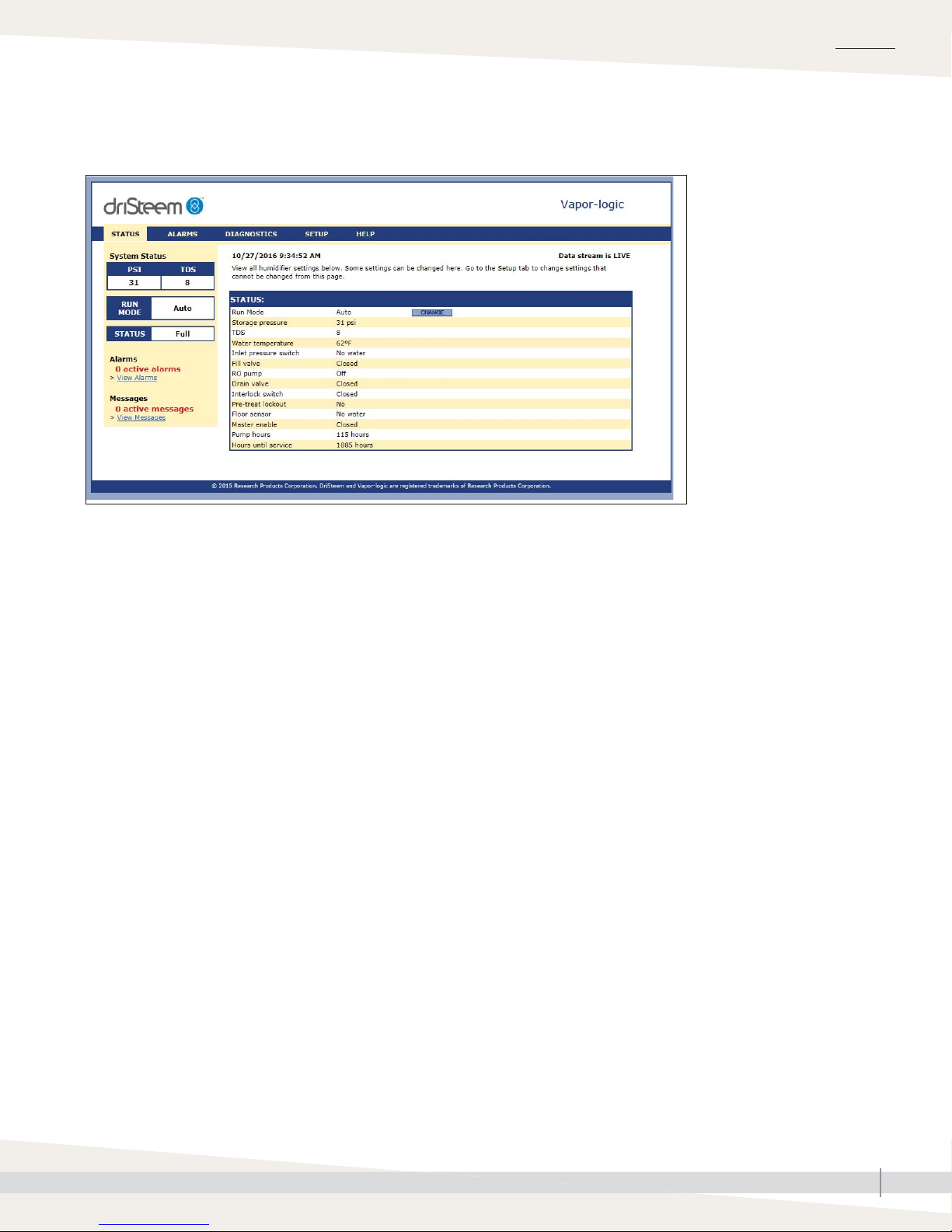
functions, with a Web interface for Ethernet access (see Figure 4-1).
The Vapor-logic Installation and Operation Manual ships with the RO system.
Refer to it for information on using the keypad/display and Web interface, and
for troubleshooting information.
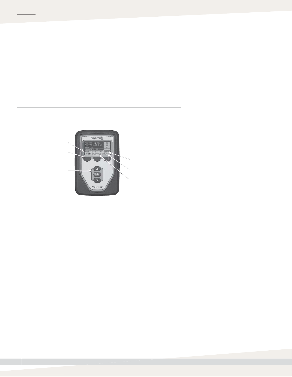
FIGURE 4-1: VAPOR-LOGIC KEYPAD/DISPLAY AND WEB INTERFACE
KEYPAD/DISPLAY
Mode
Softkeys
for direct menu access
Navigation buttons
for item selection
Tank status
System alarms
System messages
Static IP addresses
See the Vapor-logic Controller Installation and
Operation Manual shipped with the RO system
for more information about confi guring IP
addresses.
DRISTEEM RO 200 SYSTEM WATER TREATMENT SYSTEMS INSTALLATION, OPERATION, AND MAINTENANCE MANUAL
4
Product overview
WEB INTERFACE
OVERVIEW
RO SUPPLY WATER REQUIREMENTS
Supply water quality is an important component
of DriSteem reverse osmosis system reliability and
maintenance.
Water hardness can increase the reverse osmosis system
maintenance requirements.
To maximize service life and minimize maintenance for
RO systems and downstream equipment, softened water is
required with all DriSteem RO systems.
DRISTEEM RO 200 SYSTEM WATER TREATMENT SYSTEMS INSTALLATION, OPERATION, AND MAINTENANCE MANUAL
5
OVERVIEW
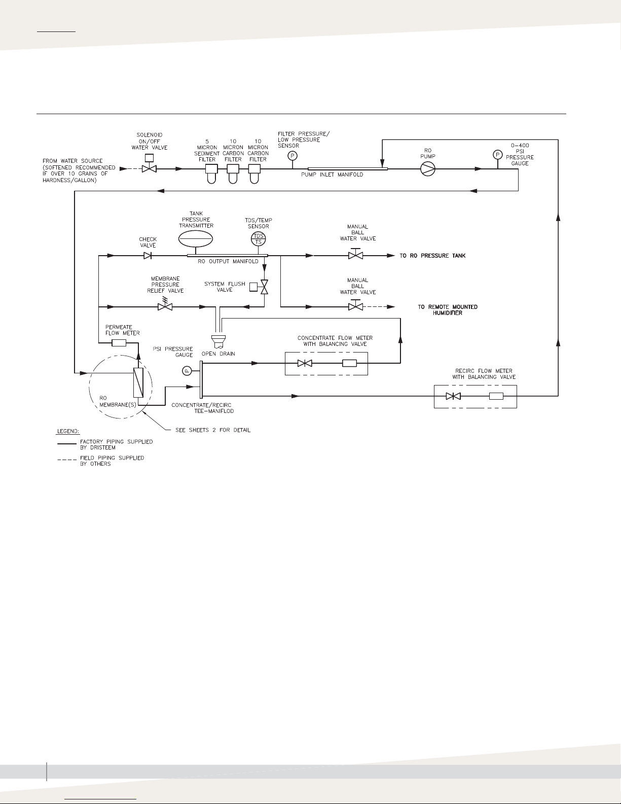
Flow schematic
FIGURE 6-1: FLOW SCHEMATIC
RO200-PIPING
DRISTEEM RO 200 SYSTEM WATER TREATMENT SYSTEMS INSTALLATION, OPERATION, AND MAINTENANCE MANUAL
6
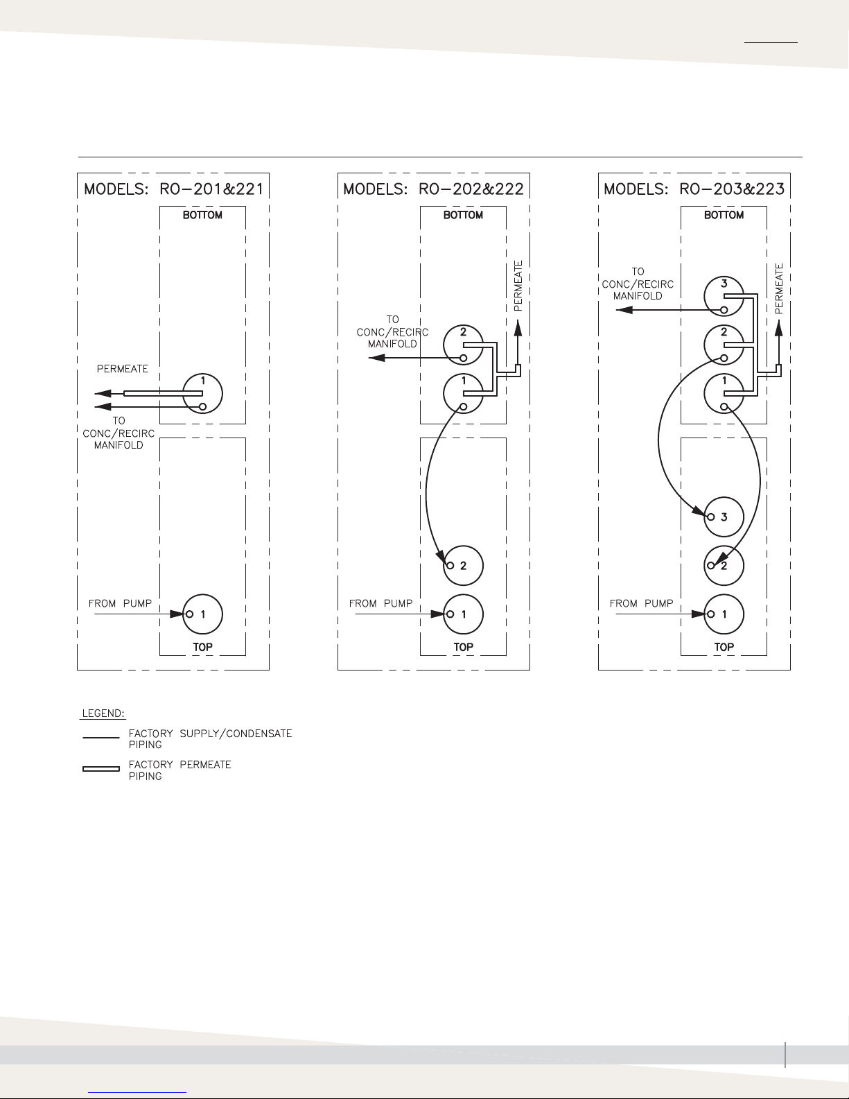
Flow schematic
FIGURE 7-1: FLOW SCHEMATIC
OVERVIEW
DRISTEEM RO 200 SYSTEM WATER TREATMENT SYSTEMS INSTALLATION, OPERATION, AND MAINTENANCE MANUAL
RO200-PIPING-1
7
 Loading...