

Page 1
READ AND SAVE THESE INSTRUCTIONS
HYDROTRUE
™
Pre-treatment Systems
Installation, Operation,
and Maintenance Manual
Page 2
WARNINGS AND CAUTIONS
Warnings and cautions
WARNING CAUTION
Indicates a hazardous situation that could result in death or
serious injury if instructions are not followed.
mc_051508_1145
WARNING
Attention installer
Read this manual before installing, and leave this manual with product owner. This product must be installed by qualified
HVAC and electrical contractors and in compliance with local, state, federal, and governing codes. Improper installation
can cause property damage, severe personal injury, or death as a result of electric shock, burns, or fire.
DriSteem Technical Support: 800-328-4447
Read all warnings and instructions
Read this manual before performing service or maintenance procedures on any part of the system. Failure to follow all
warnings and instructions could produce the hazardous situations described, resulting in property damage, personal
injury, or death.
Failure to follow the instructions in this manual can cause moisture to accumulate, which can cause bacteria and mold
growth or dripping water into building spaces. Dripping water can cause property damage; bacteria and mold growth
can cause illness.
If the IOM is missing, go to www.dristeem.com to download a replacement.
Shut down the energy source
Before performing service or maintenance procedures on any part of the system, verify that all energy sources are off.
Failure to shut down the energy source could result in fire, explosion, electrical shock, and other hazardous conditions.
These hazardous conditions could cause property damage, personal injury, or death.
Contact with energized circuits can cause property damage, severe personal injury or death as a result of electrical
shock or fire. Do not remove electrical panel cover/door or access panels until electrical power is disconnected.
Follow the shutdown procedure in the system IOM before performing service or maintenance procedures on any part of
the system.
Indicates a hazardous situation that could result in damage to or
destruction of property if instructions are not followed.
DRISTEEM PRE-TREATMENT SYSTEMS INSTALLATION, OPERATION, AND MAINTENANCE MANUAL
ii
Page 3
Warnings and cautions
WARNING
Disconnect electrical power
Disconnect electrical power before installing supply wiring or performing service or maintenance procedures on any part
of the system. Failure to disconnect electrical power could result in fire, electrical shock, and other hazardous conditions.
These hazardous conditions could cause property damage, personal injury, or death.
Contact with energized circuits can cause property damage, severe personal injury, or death as a result of electrical shock
or fire.
Follow the shutdown procedure in this manual before performing service or maintenance procedures on any part of the
system.
Electric shock hazard
If the system starts up during maintenance, severe bodily injury or death from electric shock could occur. To prevent such
start-up, follow the procedure below before performing service or maintenance procedures on this system:
1. Shut off all electrical power to the system using field-installed fused disconnect, and lock all power disconnect switches
in OFF position.
2. Close field-installed manual water supply shut-off valve.
FILL IN THE FOLLOWING INFORMATION FOR YOUR RECORDS
Date of purchase
Customer's name
Model number
Serial number
___________________________________________________________________________________________________________
___________________________________________________________________________________________________________
___________________________________________________________________________________________________________
___________________________________________________________________________________________________________
DRISTEEM PRE-TREATMENT SYSTEMS INSTALLATION, OPERATION, AND MAINTENANCE MANUAL
iii
Page 4

Table of contents
WARNINGS AND CAUTIONS ................................................ii
OVERVIEW..............................................................2
Dechlorinator specifications ...............................2
Single water softener specifications ..........................3
Duplex water softener specifications .........................4
Optional pretreatment skid mounting .........................6
Skidded single water softener and dechlorinator specifications .......7
Skidded duplex water softener and dechlorinator specifications ......8
Skidded duplex water softener specifications ...................9
INSTALLATION ......................................................... 10
Electrical installation ...................................10
Site requirements ......................................11
Start-up checklist ......................................13
System startup ........................................14
Plumbing and wiring for dual softener 21, 24, 30 inch models .....15
DRISTEEM PRE-TREATMENT SYSTEMS INSTALLATION, OPERATION, AND MAINTENANCE MANUAL
iv
Page 5

Table of contents
OPERATION ...........................................................
17
Softener and dechlorinator start-up .........................17
Loading the carbon media ...............................20
Loading the water softener media ..........................21
MAINTENANCE ........................................................ 22
Components .........................................22
Troubleshooting .......................................23
Water quality test strips .................................28
Water quality test log ..................................29
REPLACEMENT PARTS .................................................... 30
Water treatment system .................................30
WARRANTY ........................................................... 32
ATTENTION INSTALLER
Read this manual before installing.
Leave manual with product owner.
DriSteem
800-328-4447
WHERE TO FIND MORE INFORMATION
®
Technical Support
Our website:
The following documents is available on our
web site: www.dristeem.com
• Water Treatment Systems Catalog
• RO 200 series Installation, Operation,
and Maintenance Manual
• RO 400 series Installation, Operation,
and Maintenance Manual
DriCalc® sizing and selection software:
DriCalc, our software for system sizing and
selection, can be ordered at our web site.
Call us at 800-328-4447
Obtaining documents from our web site or
from DriCalc is the quickest way to view our
literature.
DRISTEEM PRE-TREATMENT SYSTEMS INSTALLATION, OPERATION, AND MAINTENANCE MANUAL
1
Page 6
OVERVIEW
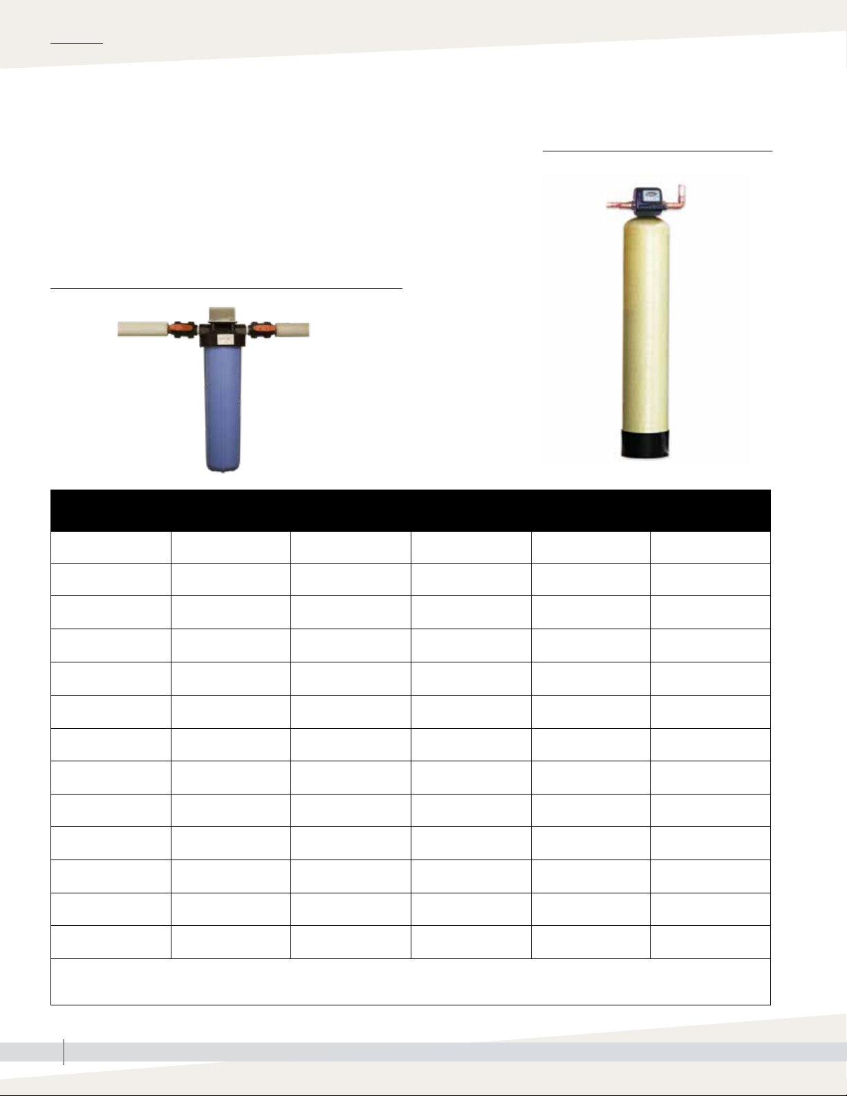
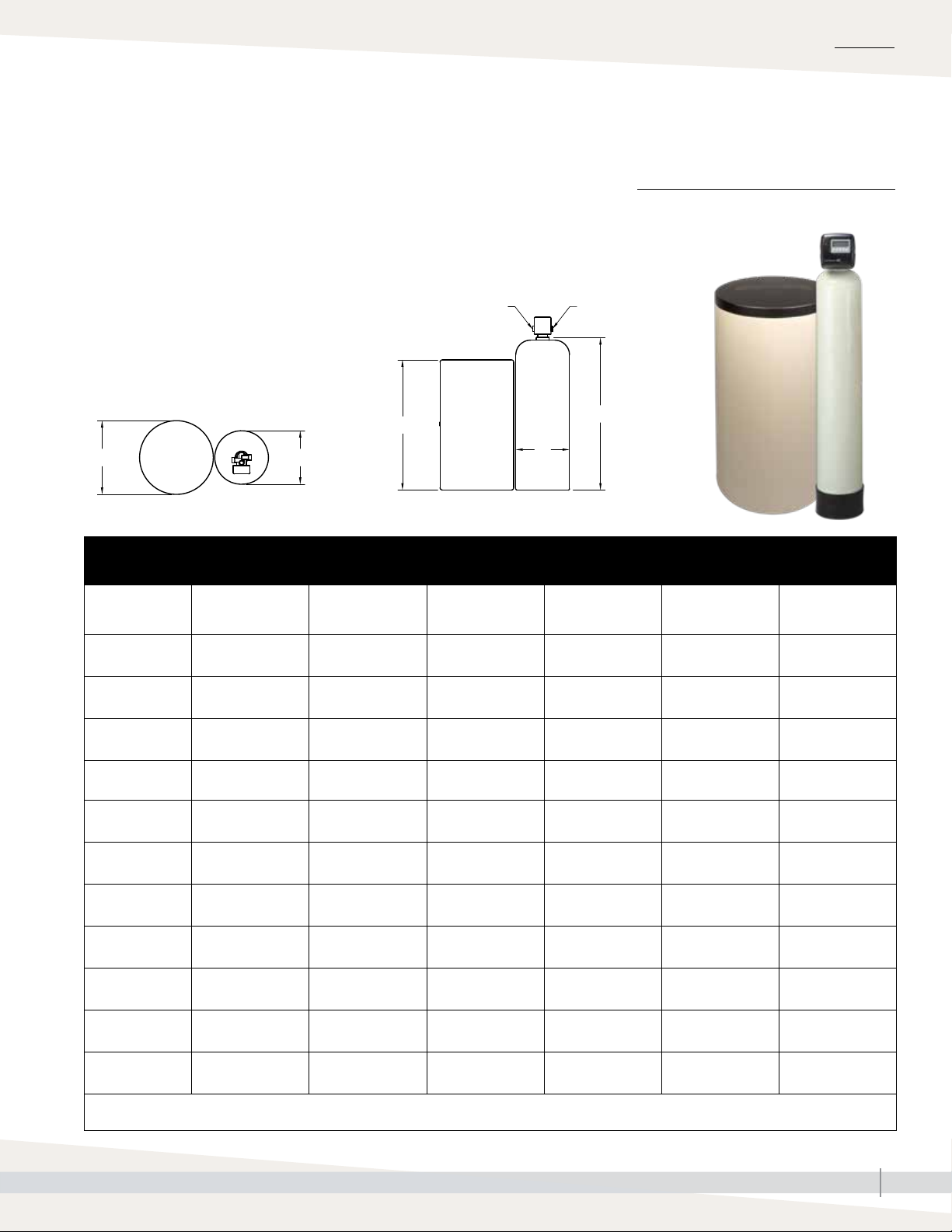
Dechlorinator specifications
DECHLORINATOR
The dechlorinator removes chlorine from the water that degrades the reverse
osmosis membranes.
120V, single-phase, 60 Hz, 5A electrical service is required for all
dechlorinator models, except for the DC-CB dechlorinator (requires no
electrical service).
FIGURE 2-2: WALL MOUNT DECHLORINATOR
Table 2-1:
Dechlorinator specifications
Dechlorinator model* Media volume
DC-CB Carbon black filter
3
DC-744
DC-844 0.75 ft
DC-948 1.00 ft
DC-1054 1.50 ft
DC-1252 2.00 ft3 (0.050 m3)
DC-1354 2.50 ft3 (0.071 m3)
DC-1465 3.00 ft3 (0.085 m3)
DC-1665 4.00 ft
DC-2162 6.00 ft3 (0.170 m3)
DC-2472 8.00 ft3 (0.227 m3)
DC-3072 12.50 ft3 (0.354 m3)
* DC-CB is wall mounted; all other models are floor mounted.
** Based on 60 to 90 psi (415 to 620 kPa) inlet pressure.
*** DC-2162, DC-2472, and DC--3072 media shipped separate, but included in shipping weight total.
0.5 ft
(0.014 m3)
3
(0.021 m3)
3
(0.028 m3)
3
(0.042 m3)
3
(0.113 m3)
Dimensions,
diameter x height
4" × 20"
(102 x 508 mm)
7" × 44"
(178 x 1118 mm)
8" x 44"
(203 x 1118 mm)
9" × 48"
(229 x 1219 mm)
10" x 54"
(254 x 1372 mm)
12" x 52"
(305 x 1321 mm)
13" x 54"
(330 x 1372 mm)
14" x 65"
(356 x 1651 mm)
16" x 65"
(406 x 1651 mm)
21" x 62"
6(533 x 1575 mm)
24" x 72"
(610 x 1829 mm)
30" x 72"
(762 x 1829 mm)
Connections, in /out Backwash flow** Shipping weight***
1" — —
1" 2.7 gpm (10.2 L/m) 100 lbs (45.4 kg)
1" 3.2 gpm (12.1 L/m) 115 lbs (52.2 kg)
1" 4.2 gpm (15.9 L/m) 130 lbs (59.0 kg)
1" 5.3 gpm (20.1 L/m) 150 lbs (68.0 kg)
1" 7.5 gpm (28.4 L/m) 190 lbs (86.2 kg)
1" 10.0 gpm (37.9 L/m) 225 lbs (102.1 kg)
1" 12.0 gpm (45.4 L/m) 335 lbs (152.0 kg)
1" 15.0 gpm (56.8 L/m) 385 lbs (174.6 kg)
1.5" 25.0 gpm (94.6 L/m) 645 lbs (292.6 kg)
1.5" 33.0 gpm (124.9 L/m) 950 lbs (430.9 kg)
2" 50.0 gpm (189.3 L/m) 1535 lbs (696.3 kg)
FIGURE 2-1: DECHLORINATOR
DRISTEEM PRE-TREATMENT SYSTEMS INSTALLATION, OPERATION, AND MAINTENANCE MANUAL
2
Page 7
Single water softener specifications
OVERVIEW
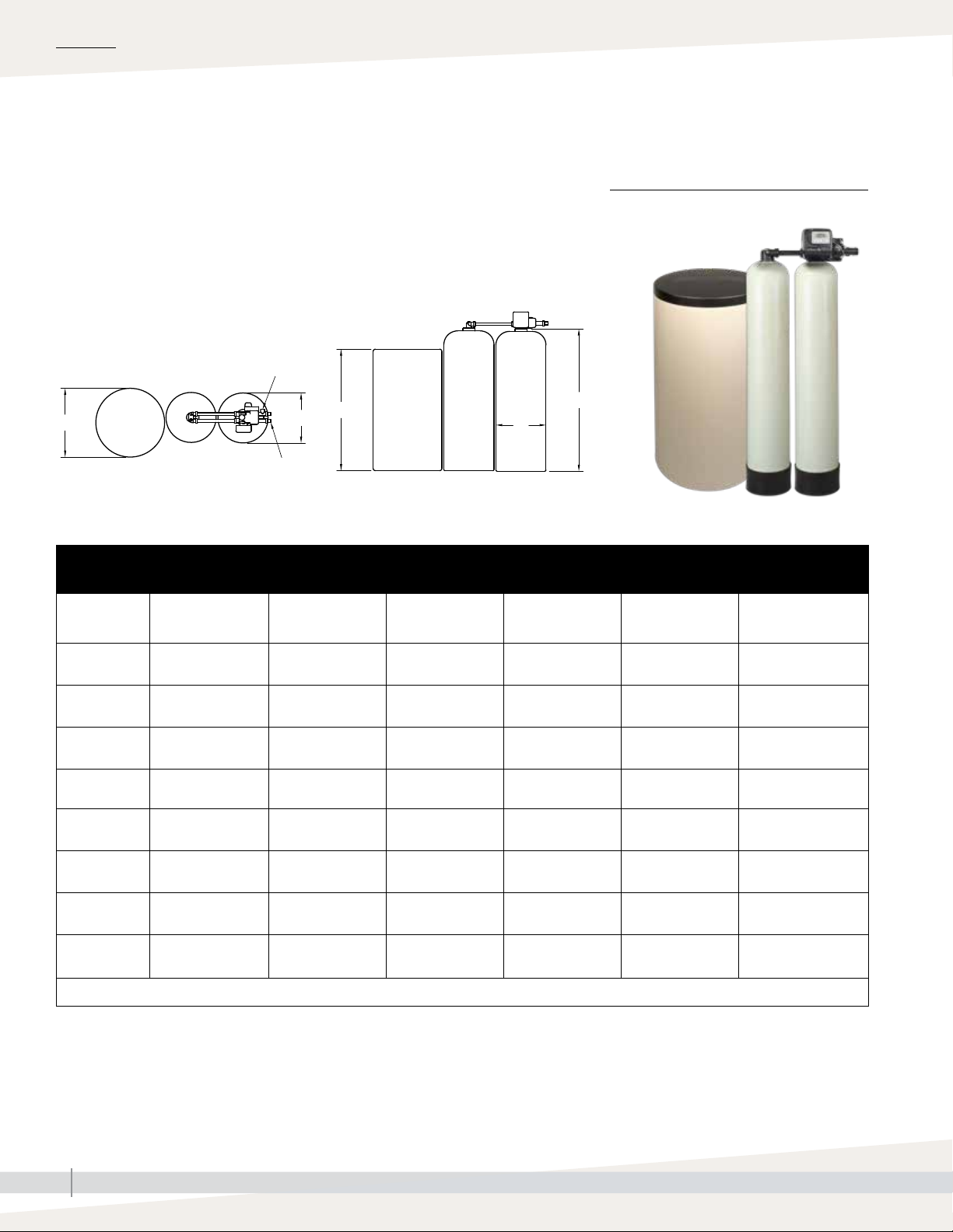
WATER SOFTENER AND BRINE TANK
The water softener and brine tank are floor-mounted and exchange water
FIGURE 3-1: SINGLE WATER SOFTENER
AND BRINE TANK
hardness for sodium.
120V, single-phase, 60 Hz, 5A electrical service is required for all water
softener models.
Water inlet
D
C
A
OM-7940
Water
outlet
B
A
Table 3-1:
Single softener and brine tank specifications
Softener model
WS-744
WS-844
WS-948
WS-1054
WS-1252
WS-1354
WS-1465
WS-1665
WS-2162
WS-2472
WS-3072
Media volume
per tank
3
0.5 ft
(0.014 m3)
3
0.75 ft
(0.021 m3)
3
1.00 ft
(0.028 m3)
3
1.50 ft
(0.042 m3)
3
2.00 ft
(0.050 m3)
3
2.50 ft
(0.071 m3)
3
3.00 ft
(0.085 m3)
3
4.00 ft
(0.113 m3)
6.00 ft3
(0.170 m3)
8.00 ft3
(0.227 m3)
12.50 ft3
(0.354 m3)
** Based on 60 to 90 psi (415 to 620 kPa) inlet pressure.
*** WS-2162, WS-2472, and WS--3072 media shipped separate, but included in shipping weight total.
Resin tank
diameter (A) x
height (B) (per tank)
7" × 44"
(178 x 1118 mm)
8" x 44"
(203 x 1118 mm)
9" × 48"
(229 x 1219 mm)
10" x 54"
(254 x 1372 mm)
12" x 52"
(305 x 1321 mm)
13" x 54"
(330 x 1372 mm)
14" x 65"
(356 x 1651 mm)
16" x 65"
(406 x 1651 mm)
21" x 62"
(533 x 1575 mm)
24" x 72"
(610 x 1829 mm)
30" x 72"
(762 x 1829 mm)
Connections,
in/out
1"
1"
1"
1"
1"
1"
1"
1"
1.5"
1.5"
2"
Backwash flow**
1.35 gpm
(4.9 L/m)
1.70 gpm
(6.4 L/m)
2.2 gpm
(8.3 L/m)
2.7 gpm
(10.2 L/m)
3.2 gpm
(12.1 L/m)
4.2 gpm
(15.9 L/m)
5.3 gpm
(20.1 L/m)
6.5 gpm
(24.6 L/m)
12.0 gpm
(45.4 L/m)
15.0 gpm
(56.8 L/m)
25.0 gpm
(94.6 L/m)
Brine tank
diameter (C) x height
(D)
18" x 33"
(457 x 838 mm)
18" x 40"
(457 x 1016 mm)
18" x 40"
(457 x 1016 mm)
18" x 40"
(457 x 1016 mm)
18" x 40"
(457 x 1016 mm)
18" x 40"
(457 x 1016 mm)
24" x 41"
(610 x 1041 mm)
24" x 41"
(610 x 1041 mm)
30" x 48"
(762 x 1219 mm)
39" x 48"
(991 x 1219 mm)
39" x 48"
(991 x 1219 mm)
Shipping weight***
110 lbs (49.9 kg)
125 lbs (56.7 kg)
140 lbs (63.5 kg)
160 lbs (72.6 kg)
200 lbs (90.7 kg)
235 lbs (106.6 kg)
345 lbs (156.5 kg)
395 lbs (179.2 kg)
655 lbs (297.1 kg)
960 lbs (435.4 kg)
1545 lbs (701.0 kg)
DRISTEEM PRE-TREATMENT SYSTEMS INSTALLATION, OPERATION, AND MAINTENANCE MANUAL
3
Page 8
OVERVIEW
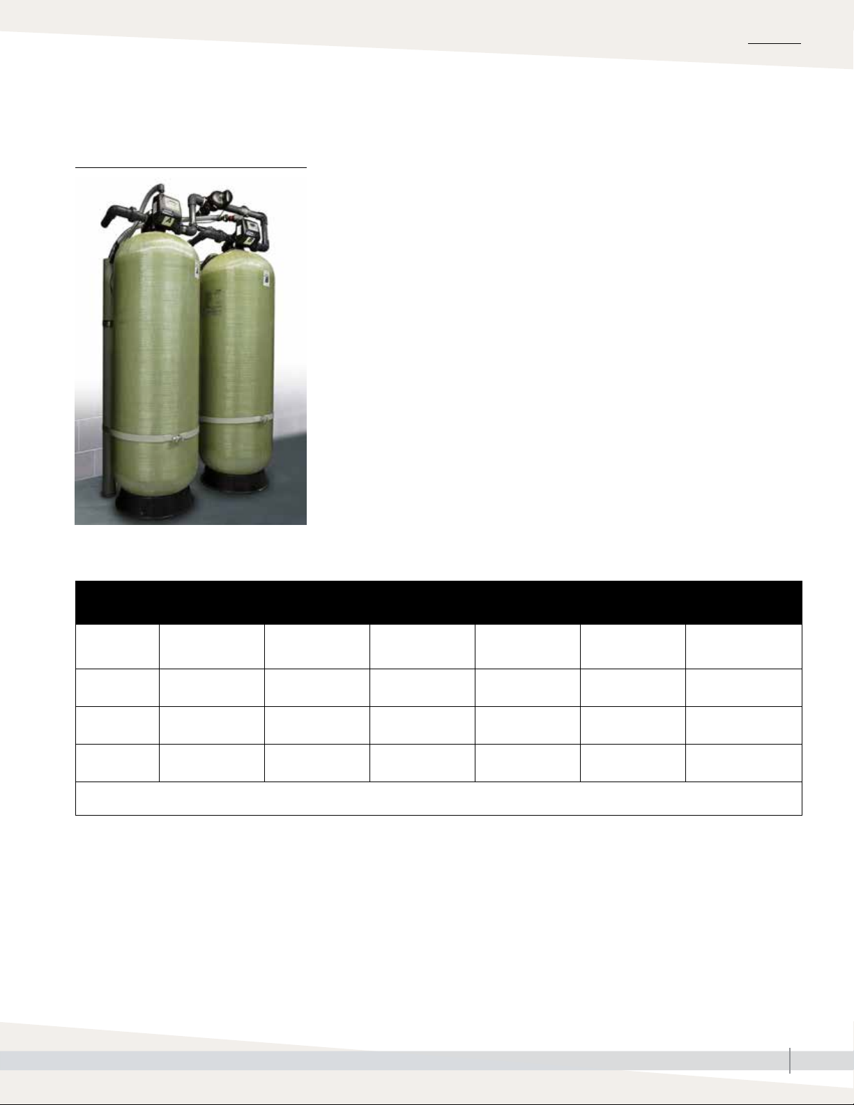
Duplex water softener specifications
WATER SOFTENER AND BRINE TANK
The water softener and brine tank are floor-mounted and exchange water
hardness for sodium.
120V, single-phase, 60 Hz, 5A electrical service is required for all water
softener models.
NPT water inlet
D
C
A
A
Water outlet
OM-7941
Table 4-1:
Duplex softener and brine tank specifications
Softener model*
WD-744
WD-844
WD-948
WD-1054
WD-1252
WD-1354
WD-1465
WD-1665
Media volume
per tank
3
0.5 ft
(0.014 m3)
3
0.75 ft
(0.021 m3)
3
1.00 ft
(0.028 m3)
3
1.50 ft
(0.042 m3)
3
2.00 ft
(0.050 m3)
3
2.50 ft
(0.071 m3)
3
3.00 ft
(0.085 m3)
3
4.00 ft
(0.113 m3)
Resin tank
diameter (A) x
height (B) (per tank)
7" × 44"
(178 x 1118 mm)
8" x 44"
(203 x 1118 mm)
9" × 48"
(229 x 1219 mm)
10" x 54"
(254 x 1372 mm)
12" x 52"
(305 x 1321 mm)
13" x 54"
(330 x 1372 mm)
14" x 65"
(356 x 1651 mm)
16" x 65"
(406 x 1651 mm)
Connections,
in/out
1"
1"
1"
1"
1"
1"
1"
1"
Backwash flow**
1.35 gpm
(4.9 L/m)
1.7 gpm
(6.4 L/m)
2.2 gpm
(8.3 L/m)
2.7 gpm
(10.2 L/m)
3.2 gpm
(12.1 L/m)
4.2 gpm
(15.9 L/m)
5.3 gpm
(20.1 L/m)
6.5 gpm
(24.6 L/m)
FIGURE 4-1: DUPLEX WATER SOFTENER
AND BRINE TANK
B
Brine tank
diameter (C) x height
Shipping weight
(D)
100 lbs (45.4 kg) 210 lbs (95.3 kg)
18" x 40"
(457 x 1016 mm)
18" x 40"
(457 x 1016 mm)
18" x 40"
(457 x 1016 mm)
18" x 40"
(457 x 1016 mm)
18" x 40"
(457 x 1016 mm)
24" x 41"
(610 x 1041 mm)
24" x 41"
(610 x 1041 mm)
250 lbs (113.4kg)
270 lbs (122.5 kg)
310 lbs (140.6 kg)
390 lbs (176.9 kg)
460 lbs (208.7 kg)
680 lbs (308.4 kg)
778 lbs (352.9 kg)
** Based on 60 to 90 psi (415 to 620 kPa) inlet pressure.
DRISTEEM PRE-TREATMENT SYSTEMS INSTALLATION, OPERATION, AND MAINTENANCE MANUAL
4
Page 9
Duplex water softener specifications
FIGURE 5-1: DUPLEX WATER SOFTENER
AND BRINE TANK
OVERVIEW
Table 5-1:
Duplex softener and brine tank specifications
Softener model*
WD-2162
WD-2472
WD-3072
** Based on 60 to 90 psi (415 to 620 kPa) inlet pressure.
*** WD-2162, WD-2472, and WD--3072 media shipped separate, but included in shipping weight total.
Media volume
per tank
3
6.00 ft
(0.170 m3)
8.00 ft3
(0.227 m3)
12.50 ft3
(0.354 m3)
Resin tank
diameter (A) x
height (B) (per tank)
21" x 62"
(533 x 1575 mm)
24" x 72"
(610 x 1829 mm)
30" x 72"
(762 x 1829 mm)
Connections,
in/out
1.5"
1.5"
2"
Backwash flow**
12.0 gpm
(45.4 L/m)
15.0 gpm
(56.8 L/m)
25.0 gpm
(94.6 L/m)
diameter (C) x height
Brine tank
(D)
30" x 48"
(762 x 1219 mm)
39" x 48"
(991 x 1219 mm)
39" x 48"
(991 x 1219 mm)
Shipping weight***
1300 lbs (589.7 kg)
1910 lbs (866.4 kg)
3080 lbs (1397.1 kg)
DRISTEEM PRE-TREATMENT SYSTEMS INSTALLATION, OPERATION, AND MAINTENANCE MANUAL
5
Page 10
OVERVIEW
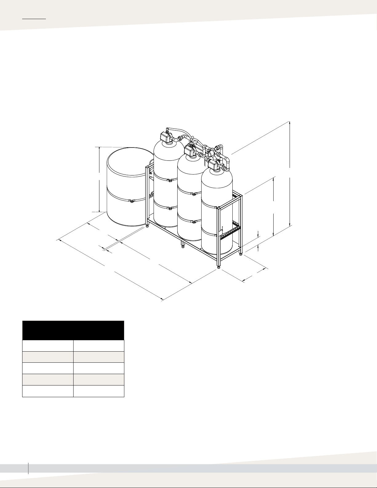
Optional pretreatment skid mounting
SELECT PRETREATMENT SKID MOUNTING FOR EASE OF INSTALLATION
Reduce installation cost and time by having pretreatment components come
pre-assembled. The DriSteem water softener(s), brine tank, and dechlorinator
have a single point water inlet, water outlet, and power for all components.
• Save time and cost on installation
• Maximize clearance
• Ensure proper installation and operation
Note: Duplex water softeners
for 21-inch diameter and
larger must have media
installed in the field.
Table 6-1:
Voltages
AC adapter U.S.
D
C
1" (25 mm)
L + C
B
54" (1372 mm)
6" (152 mm)
L
W
OM-7819a
Supply voltage 120 VAC
Supply frequency 60 Hz
Output voltage 12 VAC
Output current 500 mA
DRISTEEM PRE-TREATMENT SYSTEMS INSTALLATION, OPERATION, AND MAINTENANCE MANUAL
6
Page 11

Skidded single water softener and dechlorinator specifications
Table 7-1:
Skidded single water softener and dechlorinator
Skid size*
(outside dimensions)
L x W x H
52"x 26" x 54"
(1321 x 660 x 1372 mm)
52"x 26" x 54"
(1321 x 660 x 1372 mm)
52"x 26" x 54"
(1321 x 660 x 1372 mm)
52"x 26" x 54"
(1321 x 660 x 1372 mm)
52"x 26" x 54"
(1321 x 660 x 1372 mm)
52"x 26" x 54"
(1321 x 660 x 1372 mm)
Tank quantity on
skid
3
3
3
3
3
3
Media tank
diameter (A) x
height (B) (per
tank)
7" × 44"
(178 x 1118 mm)
8" x 44"
(203 x 1118 mm)
9" × 48"
(229 x 1016 mm)
10" x 54"
(254 x 1372 mm)
12" x 52"
(305 x 1321 mm)
13" x 54"
(330 x 1372 mm)
Connections,
in/out
1"
1"
1"
1"
1"
1"
Backwash flow***
1.35 gpm
(4.9 L/m)
1.70 gpm
(6.4 L/m)
2.2 gpm
(8.3 L/m)
2.7 gpm
(10.2 L/m)
3.2 gpm
(12.1 L/m)
4.2 gpm
(15.9 L/m)
Brine tank
diameter (C) x
height (D)
18" x 33"
(457 x 838 mm)
18" x 40"
(457 x 1016 mm)
18" x 40"
(457 x 1016 mm)
18" x 40"
(457 x 1016 mm)
18" x 40"
(457 x 1016 mm)
18" x 40"
(457 x 1016 mm)
OVERVIEW
Shipping weight
370 lbs
(167.8 kg)
400 lbs
(181.4 kg)
420 lbs
(190.5 kg)
470 lbs
(213.2 kg)
530 lbs
(240.4 kg)
620 lbs
(281.2 kg)
66"x 28" x 54"
(1676 x 711 x 1372 mm)
66"x 28" x 54"
(1676 x 711 x 1372 mm)
100"x 34" x 54"
(2540 x 864 x 1372 mm)
66"x 28" x 54" **
(1676 x 711 x 1372 mm)
82"x 28" x 54" **
(2083 x 711 x 1372 mm)
* Non-skidded pre-treatment dimensions are 4" (102 mm) less.
** Skid does not include brine tank. The brine tank is floor mounted.
*** Based on 60 to 90 psi (415 to 620 kPa) inlet pressure.
3
3
3
2
2
14" x 65"
(356 x 1651 mm)
16" x 65"
(406 x 1651 mm)
21" x 62"
(533 x 1575 mm)
24" x 72"
(610 x 1829 mm)
30" x 72"
(762 x 1829 mm)
1"
1"
1.5"
1.5"
2"
5.3 gpm
(20.1 L/m)
6.5 gpm
(24.6 L/m)
12.0 gpm
(45.4 L/m)
15.0 gpm
(56.8 L/m)
25.0 gpm
(94.6 L/m)
24" x 41"
(610 x 1041 mm)
24" x 41"
(610 x 1041 mm)
30" x 48"
(762 x 1219 mm)
39" x 48"
(991 x 1219 mm)
39" x 48"
(991 x 1219 mm)
860 lbs
(390.1 kg)
910 lbs
(412.8 kg)
1540 lbs
(698.5 kg)
2090 lbs
(948.0 kg)
3280 lbs
(1487.8 kg)
DRISTEEM PRE-TREATMENT SYSTEMS INSTALLATION, OPERATION, AND MAINTENANCE MANUAL
7
Page 12

OVERVIEW
Skidded duplex water softener and dechlorinator specifications
Table 8-1:
Skidded duplex water softener and dechlorinator
Skid size
(outside dimensions)
L x W x H
66"x 28" x 54"
(1676 x 711 x 1372 mm)
66"x 28" x 54"
(1676 x 711 x 1372 mm)
66"x 28" x 54"
(1676 x 711 x 1372 mm)
66"x 28" x 54"
(1676 x 711 x 1372 mm)
66"x 28" x 54"
(1676 x 711 x 1372 mm)
66"x 28" x 54"
(1676 x 711 x 1372 mm)
Tank quantity
on skid
4
4
4
4
4
4
Media tank
diameter (A) x
height (B) (per tank)
7" × 44"
(178 x 1118 mm)
8" x 44"
(203 x 1118 mm)
9" × 48"
(229 x 1016 mm)
10" x 54"
(254 x 1372 mm)
12" x 52"
(305 x 1321 mm)
13" x 54"
(330 x 1372 mm)
Connections,
in/out
1"
1"
1"
1"
1"
1"
Backwash flow***
1.35 gpm
(4.9 L/m)
1.7 gpm
(6.4 L/m)
2.2 gpm
(8.3 L/m)
2.7 gpm
(10.2 L/m)
3.2 gpm
(12.1 L/m)
4.2 gpm
(15.9 L/m)
Brine tank
diameter (C) x height (D)
18" x 33"
(457 x 838 mm)
18" x 40"
(457 x 1016 mm)
18" x 40"
(457 x 1016 mm)
18" x 40"
(457 x 1016 mm)
18" x 40"
(457 x 1016 mm)
18" x 40"
(457 x 1016 mm)
Shipping weight
490 lbs
(222.3 kg)
545 lbs
(247.2 kg)
575 lbs
(260.8 kg)
640 lbs
(290.3 kg)
760 lbs
(344.7 kg)
865 lbs
(392.4 kg)
82"x 28" x 54"
(2083 x 711 x 1372 mm)
82"x 28" x 54"
(2083 x 711 x 1372 mm)
82"x 28" x 54" **
(2083 x 711 x 1372 mm)
82"x 28" x 54" **
(2083 x 711 x 1372 mm)
100"x 34" x 54" **
(2540 x 864 x 1372 mm)
* Non-skidded pre-treatment dimensions are 4" (102 mm) less.
** Skid does not include brine tank. The brine tank is floor mounted.
*** Based on 60 to 90 psi (415 to 620 kPa) inlet pressure.
4
4
3
3
3
14" x 65"
(356 x 1651 mm)
16" x 65"
(406 x 1651 mm)
21" x 62"
(533 x 1575 mm)
24" x 72"
(610 x 1829 mm)
30" x 72"
(762 x 1829 mm)
1"
1"
1.5"
1.5"
2"
5.3 gpm
(20.1 L/m)
6.5 gpm
(24.6 L/m)
12.0 gpm
(45.4 L/m)
15.0 gpm
(56.8 L/m)
25.0 gpm
(94.6 L/m)
24" x 41"
(610 x 1041 mm)
24" x 41"
(610 x 1041 mm)
30" x 48"
(762 x 1219 mm)
39" x 48"
(991 x 1219 mm)
39" x 48"
(991 x 1219 mm)
1215 lbs
(551.1 kg)
1363 lbs
(618.2 kg)
2145 lbs
(972.9 kg)
3060 lbs
(1387.9 kg)
4855 lbs
(2202.2 kg)
DRISTEEM PRE-TREATMENT SYSTEMS INSTALLATION, OPERATION, AND MAINTENANCE MANUAL
8
Page 13

Skidded duplex water softener specifications
Table 9-1:
Skidded duplex water softener
Skid size
(outside dimensions)
L x W x H
52"x 26" x 54"
(1321 x 660 x 1372 mm)
52"x 26" x 54"
(1321 x 660 x 1372 mm)
52"x 26" x 54"
(1321 x 660 x 1372 mm)
52"x 26" x 54"
(1321 x 660 x 1372 mm)
52"x 26" x 54"
(1321 x 660 x 1372 mm)
52"x 26" x 54"
(1321 x 660 x 1372 mm)
Tank quantity on
skid
3
3
3
3
3
3
Media tank
diameter (A) x
height (B) (per
tank)
7" × 44"
(178 x 1118 mm)
8" x 44"
(203 x 1118 mm)
9" × 48"
(229 x 1016 mm)
10" x 54"
(254 x 1372 mm)
12" x 52"
(305 x 1321 mm)
13" x 54"
(330 x 1372 mm)
Connections,
in/out
1"
1"
1"
1"
1"
1"
Backwash flow***
1.35 gpm
(4.9 L/m)
1.7 gpm
(6.4 L/m)
2.2 gpm
(8.3 L/m)
2.7 gpm
(10.2 L/m)
3.2 gpm
(12.1 L/m)
4.2 gpm
(15.9 L/m)
Brine tank
diameter (C) x
height (D)
18" x 33"
(457 x 838 mm)
18" x 40"
(457 x 1016 mm)
18" x 40"
(457 x 1016 mm)
18" x 40"
(457 x 1016 mm)
18" x 40"
(457 x 1016 mm)
18" x 40"
(457 x 1016 mm)
OVERVIEW
Shipping weight
370 lbs
(167.8 kg)
410 lbs
(185.9 kg)
430 lbs
(195.0 kg)
470 lbs
(213.2 kg)
550 lbs
(249.5 kg)
620 lbs
(281.2 kg)
66"x 28" x 54"
(1676 x 711 x 1372 mm)
66"x 28" x 54"
(1676 x 711 x 1372 mm)
100"x 34" x 54"
(2540 x 864 x 1372 mm)
66"x 28" x 54" **
(1676 x 711 x 1372 mm)
82"x 28" x 54" **
(2083 x 711 x 1372 mm)
* Non-skidded pre-treatment dimensions are 4" (102 mm) less.
** Skid does not include brine tank. The brine tank is floor mounted.
*** Based on 60 to 90 psi (415 to 620 kPa) inlet pressure.
3
3
3
2
2
14" x 65"
(356 x 1651 mm)
16" x 65"
(406 x 1651 mm)
21" x 62"
(533 x 1575 mm)
24" x 72"
(610 x 1829 mm)
30" x 72"
(762 x 1829 mm)
1"
1"
1.5"
1.5"
2"
5.3 gpm
(20.1 L/m)
6.5 gpm
(24.6 L/m)
12.0 gpm
(45.4 L/m)
15.0 gpm
(56.8 L/m)
25.0 gpm
(94.6 L/m)
24" x 41"
(610 x 1041 mm)
24" x 41"
(610 x 1041 mm)
30" x 48"
(762 x 1219 mm)
39" x 48"
(991 x 1219 mm)
39" x 48"
(991 x 1219 mm)
860 lbs
(390.1 kg)
958 lbs
(434.5 kg)
1540 lbs
(698.5 kg)
2090 lbs
(948.0 kg)
3280 lbs
(1487.8 kg)
DRISTEEM PRE-TREATMENT SYSTEMS INSTALLATION, OPERATION, AND MAINTENANCE MANUAL
9
Page 14

INSTALLATION
Electrical installation
The control valve and fittings are not designed to support the weight of the
system or the plumbing.
• Teflon tape is recommended to be used on all threads. Do not use pipe
dope, as it may break down the plastics in the control valve.
• Allow one foot of clearance to service WS1.5 valves and two feet of
clearance to service WS2 and WS2QC valves.
• The valve will withstand transportation and storage temperatures of -13 °F
(-25 °C) to 131 °F (55 °C) and for short periods up to 158 °F (70 °C). If
valve has been exposed to freezing conditions let valve warm up to room
temperature before running water through it. The valve has been packaged
to prevent damage from the effects of normal humidity, vibration and
shock.
SINGLE SOFTENER LOCKOUT SWITCH
Single softeners have a RO lockout switch if it is desired to lockout the RO
system to prevent any hard water passing to the RO system when the softeners
are in backwash. See Figure 10-1 for connections to the RO system lockout
terminals.
FIGURE 10-1: SINGLE SOFTENER LOCKOUT SWITCH WIRING
CAUTION
Do not use Vaseline, oils, other
hydrocarbon lubricants or spray
silicone anywhere. A silicone lubricant
may be used on black o-rings but is
not necessary.
CAUTION
Hydrocarbons such as kerosene,
benzene, gasoline, etc., may damage
products that contain o-rings or
plastic components. Exposure to such
hydrocarbons may cause the products
to leak. Do not use the products(s)
contained in this document on water
supplies that contain hydrocarbons
such as kerosene, benzene, gasoline,
etc.
WMS_Lockout_wiring
CAUTION
DriSteem water meters should not
be used as the primary monitoring
device for critical or health effect
applications.
To lockout terminals on RO system
DRISTEEM PRE-TREATMENT SYSTEMS INSTALLATION, OPERATION, AND MAINTENANCE MANUAL
10
Page 15

Site requirements
SITE REQUIREMENTS
1. The plug in Power Adapter is for dry locations only, and should be
connected to an uninterrupted outlet installed within 15 feet (4.57 meters)
of the water conditioner. If the Power Adapter cord has not yet been
connected to the control valve, remove the control valve cover and the
drive bracket, and thread the Power Adapter cord through the hole in the
back plate. Reinstall the drive bracket. Weave the cord through the hooks
on the right hand side of the drive bracket and connect the end to the
four-prong connector on the printed circuit board. Replace the cover, and
plug the Power Adapter into an uninterrupted outlet.
2. The tanks should be on a firm, level surface.
3. All plumbing should be done in accordance with local codes.
4. Do not locate unit where it or its connections (including the drain and
overflow lines) will ever be subjected to room temperatures below 40° F
(4° C).
INSTALLATION
5. INLET/OUTLET PLUMBING: Connect to a supply line downstream of
outdoor spigots. Install an inlet shutoff valve and plumb to the unit’s inlet.
Installation of a bypass valve is recommended. If using plastic fittings,
ground the water conditioner per local electrical codes. Do not install
any water conditioner with less than 10 feet of piping between its outlet
and the inlet of a water heater. If a water meter is used, install the water
meter on the outlet side of the control valve. The turbine assembly may
be oriented in any direction, but is usually oriented pointing up to reduce
drainage out of the pipe during service.
6. Locate the water conditioner so the distance between the drain and the
water conditioner is as short as possible. All units are shipped without a
drain line flow control washer. Correctly size the drain line and install an
appropriately sized drain line flow control. 1.5” valves are shipped with
a ¾” fitting that can be used with the drain line flow controls up to 10
gpm, or an optional 1” fitting can be purchases to be used with drain line
flow controls up to 25 gpm. For higher backwash rates, the adapter can
be removed and the 1 ¼” NPT threaded drain outlet can be used. For 2”
valves the drain outlet is 1.5” NPT threads. Solder joints near the drain
must be done prior to connecting the drain line flow control fitting. Leave
at least 6” (152.4mm) between the drain line flow control fitting and
the solder joints to prevent heat from damaging the flow control. Avoid
elevating the drain line above the control valve where possible. Discharge
the drain line through an air gap to a receptacle in accordance with local
plumbing codes.
IMPORTANT: Never insert a drain line directly into a drain, sewer line or trap.
Always allow and air gap between the drain line and the receptacle to prevent
back siphonage.
DRISTEEM PRE-TREATMENT SYSTEMS INSTALLATION, OPERATION, AND MAINTENANCE MANUAL
11
Page 16

INSTALLATION
Site requirements
7. Regenerant tanks should be accessible for easy refilling. If the control
valve is to be used to regenerate the water conditioner with brine
(saturated salt solution) or other regenerants, use a polyethylene tube to
connect the brine valve contained in the regenerant tank to the regenerant
port on the control valve. It is recommended the brine valve contain a
safety float. The 1.5” control valve’s regenerant port has a ½” fitting.
Note: ½” tubing that runs longer than 6 feet may restrict draw rates with
G and H injectors. A 5/8” fitting is also available.
The 2” control valve regenerant port has a 1” threaded connection. To
ensure acceptable operation of the injectors, use 1” pipe to connect to the
brine tank.
An overflow drain line from the regenerant tank that discharges into
an acceptable drain is recommended, as a regenerant overflow could
damage furnishings or the building structure. Connect a line to the
overflow fitting on the regenerant tank. If an overflow fitting is not already
installed on the regenerant tank, install one. Do not elevate the overflow
drain line. Discharge the overflow drain line through an air gap to a
receptacle in accordance with local plumbing codes.
FIGURE 12-1: WATER SOFTENER CLEARANCE
Softener tanks
Minimum 4" (102 mm)
clearance
DechlorinatorBrine tank
OM-7906a
DRISTEEM PRE-TREATMENT SYSTEMS INSTALLATION, OPERATION, AND MAINTENANCE MANUAL
12
Page 17

INSTALLATION
Start-up checklist
If an item in the Start-up checklist below does not apply to your system, skip to the next item and continue the process.
☐ Read this manual and all other information that was provided with your system.
☐ Verify that all field wiring is done according to the instructions in this manual and in the unit wiring diagram.
☐ Confirm that proper grounding and an approved earth ground are provided.
☐ Slowly turn on the water supply and confirm there are no leaks.
☐ Add water to the brine tank. 1/3 water (12-inches) water and 2/3 salt.
☐ Systems with tank-style carbon filter with control valve: Ensure that elastomeric Drain Line Flow Control restrictor
washer is installed correctly in drain outlet plumbing assembly. This is required to prevent overflow and potential
carry-over of carbon to the drain system.
See “Dechlorinator” on Page 22 of this manual.
☐ Inspect to insure that no flexible plumbing lines have been kinked or damaged during installation.
DRISTEEM PRE-TREATMENT SYSTEMS INSTALLATION, OPERATION, AND MAINTENANCE MANUAL
13
Page 18

INSTALLATION
System startup
1. After installation is completed, turn on the supply water to check for leaks.
2. Fully open a cold water faucet downstream of the system.
3. Allow water to run until clear.
4. Close the cold water faucet.
5. Turn off the supply water.
6. The system is now ready for startup.
SYSTEM STARTUP
7. Initiate manual regeneration of the control valve to regenerate: press the
REGEN button for three seconds.
8. Ensure drain line flow remains steady for 10 minutes or until clear. Step
through the different regeneration cycles by pressing the REGEN button
again.
9. Observe regeneration effluent and continue to regenerate until discharge
is clear. Steps 7 and 8 may need to be repeated as necessary.
10. Observe that the brine tank is filling during brine tank refill cycle.
11. Install brine tank overflow line. Attach plastic tubing to the fittings from
the brine tank and run to an open drain. This drain line will not be under
pressure. Do not tie into the backwash drain line. This line should be
higher than the normal drain line, and must be a separate line from fitting
to drain. It is a safety overflow drain and will not be in use during normal
operation.
12. Observe that the valve advances through the different regeneration cycles
and ends in service. Step through the different regeneration cycles by
pressing REGEN.
13. Fill brine tank with salt. Salt may be sodium chloride (NaCl) or potassium
chloride (KCI). Fill tank to only 2/3 full. Note: The brine tank holds a
large quantity of salt, so you will not need to refill at frequent intervals.
Refilling the brine tank with salt should be performed after your system
is successfully installed and has been operating trouble-free. Brine tank
should be refilled with salt at least two hours before the next generation is
performed.
14. Review Tables 17-1 and 18-1 to ensure settings are properly
programmed before placing the softener in service.
DRISTEEM PRE-TREATMENT SYSTEMS INSTALLATION, OPERATION, AND MAINTENANCE MANUAL
14
Page 19

Plumbing and wiring for dual softener 21, 24, 30 inch models
Note:
• All plumbing is to be done in accordance with state and local codes.
• The control valve, fittings and/or bypass are designed to accommodate minor plumbing
misalignments but are not designed to support the weight of a system or the plumbing.
• Connect to a supply line downstream of outdoor spigots. Install an inlet shutoff valve and plumb
them to the unit’s inlet. Installation of a bypass valve is recommended. If using plastic fittings,
ground the water conditioner per local electrical codes.
• Do not use pipe dope or other sealant on threads. Use teflon tape on threaded inlet, outlet and
drain fittings.
1. Plumb the Motorized Alternating Valve (MAV) according to Figure 15-1. Note: Ensure that
the valve labeled “Alt A” is connected to the “A” port on the MAV, and the valve labeled “Alt
B” is connected to the “B” port.
2. Install connecting piping between raw water source and input pipe on control valve.
3. Install drain line from control valve to a free flowing drain. Solder joints near the drain must
be done prior to connecting the drain line flow control fitting. Leave at least 6” (152.4mm)
between the drain line flow control fitting and the solder joints to prevent heat from damaging
the flow control. Avoid elevating the drain line above the control valve where possible.
Discharge the drain line through an air gap to a receptacle in accordance with local plumbing
codes.
INSTALLATION
Important: Never insert a drain line directly into a drain, sewer line or trap. Always allow an air
gap between the drain line and the receptacle to prevent back siphonage.
FIGURE 15-1: PLUMBING THE MOTORIZED ALTERNATING VALVE
DRISTEEM PRE-TREATMENT SYSTEMS INSTALLATION, OPERATION, AND MAINTENANCE MANUAL
15
Page 20

INSTALLATION
Plumbing and wiring for dual softener 21, 24, 30 inch models
4. Install the water meter on the outlet side of the control valve. The meter may be threaded
directly into the valve or may be plumbed separately downstream of the unit. Ensure the arrow
on the meter body is going the same direction as the water flow. The turbine assembly may
be oriented in any direction, but is usually oriented pointing up to reduce drainage out of the
pipe during service. Meter can be installed horizontally or vertically.
5. Install piping between meter output and point of use.
6. Use a tee to install Brine/Refill line between brine tank and regenerant line.
7. Install an overflow drain line from the regenerant tank. Connect a line to the 1” overflow fitting
on the regenerant tank. Do not elevate the overflow drain line. Discharge the overflow drain
line through an air gap to a recaptacle in accordance with local plumbing codes.
VALVE WIRING
1. Connect MAV Motor Wire & Interconnect cable to valve head Alt A:
• On the backside of the valve, remove the strain relief cover with a screwdriver.
• Remove the cover of the valve by pulling out on the release tabs located on each side of
the cover.
• Feed the MAV motor wire and interconnect (communication) cable through the hole in the
back of the valve.
• Connect the MAV motor wire to the two pin connector labeled “DRIVE” on the PC Board.
• Connect the interconnect (communication) cable to the three pin connector labelled
“INTERCONNECT CABLE” on the PC Board.
• After connecting the cables, weave the wires through the strain relief on the backside of the
valve, and replace the strain relief cover and screw. Replace the valve cover.
2. Connect MAV Cables to valve head Alt B:
• On the backside of the valve, remove the strain relief cover with a screwdriver.
• Remove the cover of the valve by pulling out on the release tabs located on each side of
the cover.
• Feed the other end of the interconnect (communication) cable & the meter cable through the
hole in the back of the valve.
• Connect the interconnect cable to the three pin connector labelled “INTERCONNECT
CABLE” on the PC Board.
• After connecting the cables, weave the wires through the strain relief on the backside of the
valve, and replace the strain relief cover and screw. Replace the valve cover.
• Ensure meter cable is connected to the meter assembly.
DRISTEEM PRE-TREATMENT SYSTEMS INSTALLATION, OPERATION, AND MAINTENANCE MANUAL
16
Page 21

Softener and dechlorinator start-up
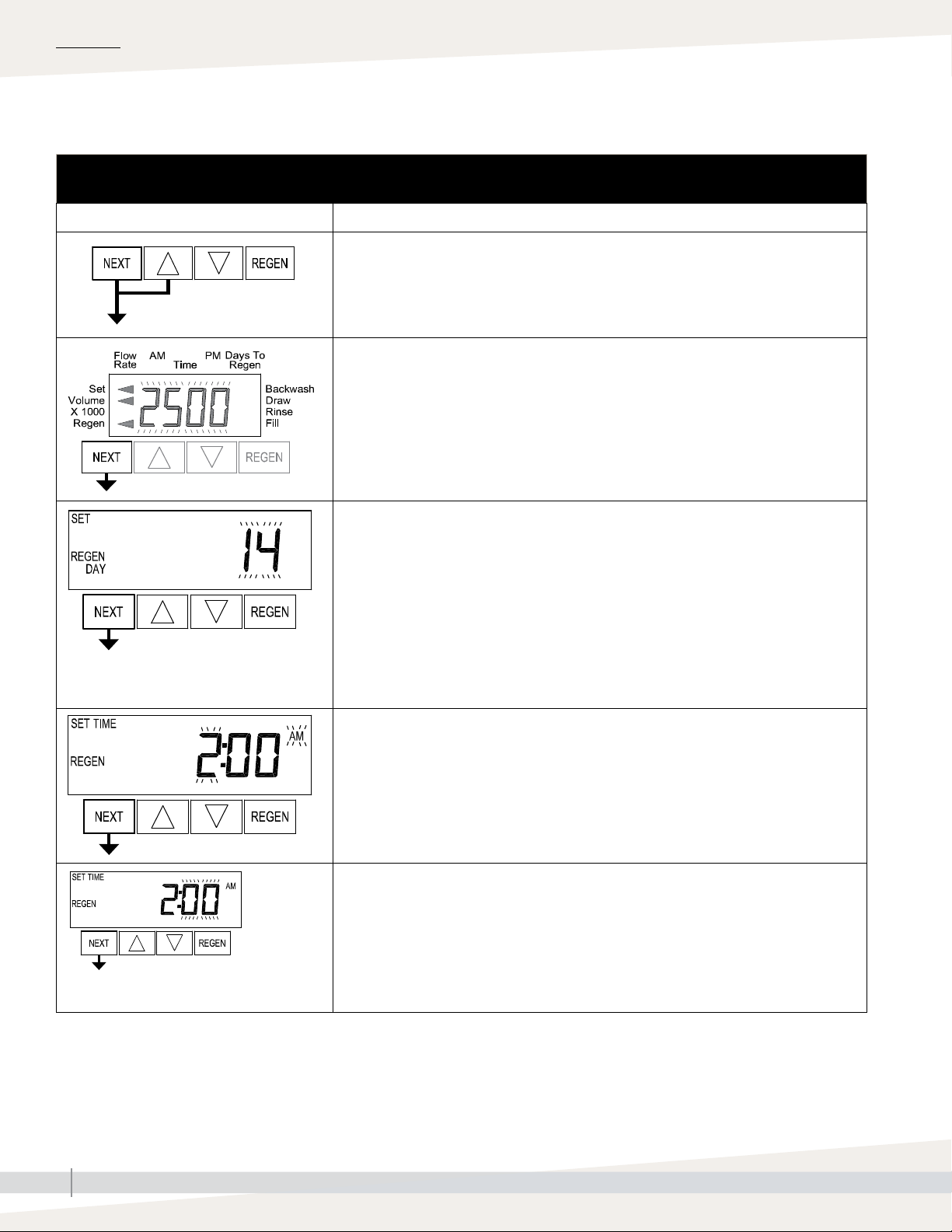
Table 17-1:
Set time of day
Buttons Description
1. Press NEXT until the time of day screen is displayed.
2. Press and hold the or until the SET indicator is displayed and the hour flashes.
3. Press the or until the correct hour is displayed.
4. Press NEXT. The minutes will flash.
5. Press or until the correct minute is displayed.
6. Press NEXT to return to the display screen.
Note: In the event of a prolonged power outage, time of day flashes, indicating that it needs to
be reset. All other information will be stored in memory no matter how long the power outage.
Complete the steps above to reset the time of day.
OPERATION
DRISTEEM PRE-TREATMENT SYSTEMS INSTALLATION, OPERATION, AND MAINTENANCE MANUAL
17
Page 22
OPERATION
SETTINGS
Softener start-up
Table 18-1:
Softener start-up
Buttons Description
To enter Installer Display press NEXT and simultaneously for about 5 seconds and release.
Press or to enter the volumetric capacity in gallons. See Table 19-1. Press NEXT to go to
the Day Override screen. Press REGEN to return to previous step.
Day Override: When volume capacity is set to “oFF”, sets the number of days between
regenerations. When volume capacity is set to AUTO or to a volume, sets the maximum number
of days between regenerations. If value set to “oFF”, regeneration initiation is triggered solely by
volume used.
If value is set in days (allowable range from 1 to 28) regeneration initiation will be called for on
that day regardless of actual water usage. Set Day Override using or :
• number of days between regeneration (1 to 28); or
• “oFF”.
Press NEXT. Press REGEN to return to previous step.
Next Regeneration Time (hour): Set the hour of day for regeneration using or . The default
time is 2:00. This display will show “REGEN on 0 GAL” if “on 0” is selected in Set Regeneration
Time
Press NEXT. Press REGEN to return to previous step.
Next Regeneration Time (minutes): Set the minutes of day for regeneration using or .
Press NEXT to exit Installer Display Settings. Press REGEN to return to previous step.
EXIT INSTALLER DISPLAY
DRISTEEM PRE-TREATMENT SYSTEMS INSTALLATION, OPERATION, AND MAINTENANCE MANUAL
18
Page 23

Softener start-up
OPERATION
SALT USAGE AND GRAINS CAPACITY SETTINGS
The softener can be set to use different amounts of salt per regeneration. The
higher the quantity of salt used, the higher the resin's hardness removing
capacity will be. DriSteem recommends using 10lbs/cu. ft. Alternatively,
higher salt usage may be set in order to maximize resin capacity between
regenerations, or a lower salt usage settings can be used to reduce salt
consumption, but this will result in more frequent regeneration.
• To find volume capacity:
• Find the model and desired salt setting from Table 19-1. DriSteem
recommends using 10lbs/cu. ft. to find the total grains capacity for the
tank model.
• Divide the grains capacity by the number of grains per gallon of
hardness present in the feed water. (Example: If feed water is 10
grains per gallon hardness, the WS-744 [with 10cu. ft. salt setting]
has 14,500 grains capacity. 14,500 ÷ 10 = 1,450 gallon capacity).
• To find brine fill time:
• Use number from Brine fill time column for the model number in the
appropriate salt settings column.
Water softener salt quantity estimate
Total brine tank volume (cubic inches)= π r2 h
• r = radius of the brine tank in inches
• h = height of the brine tank in inches
Pounds of salt needed =
2/3 x (Brine Tank Volume / 1728) x 28
Example
For a WS-1465 softener, the pounds of salt
needed = 2/3 x (π x 242 x 41 / 1728) x 28
= 200 lbs
Table 19-1:
Capacity (per tank) at various pounds of salt per regeneration settings
Grains
10 lbs/cu. ft.
(Recommended)
Salt used
per regen
Brine
fill time
(minutes)
Grains
capacity
7.5 lbs/cu. ft. 5 lbs/cu. ft.
Salt used
per regen
Brine
fill time
(minutes)
Grains
capacity
Salt used
per regen
Brine
fill time
(minutes)
15 lbs/cu. ft.
Model
WS-744 15,000 7.5 5.0 14,500 5.0 3.3 12,850 3.8 2.5 10,000 2.5 1.7
WS-844 18,000 9.0 6.0 17,400 6.0 4.0 15,420 4.5 3.0 12,000 3.0 2.0
WS-948 22,500 11.3 7.5 21,750 7.5 5.0 19,275 5.6 3.8 15,000 3.8 2.5
WS-1054 37,500 18.8 12.5 36,250 12.5 8.3 32,125 9.4 6.3 25,000 6.3 4.1
WS-1252 52,500 26.3 17.5 50,750 17.5 11.6 44,975 13.1 8.8 35,000 8.8 5.8
WS-1354 60,000 30.0 20.0 58,000 20.0 13.2 51,400 15.0 10.0 40,000 10.0 6.6
WS-1465 90,000 45.0 30.0 87,000 30.0 19.8 77,100 22.5 15.0 60,000 15.0 9.9
WS-1665 105,000 52.5 35.0 101,500 35.0 23.1 89,950 26.3 17.5 70,000 17.5 11.6
WS-2162 198,000 90.0 60.0 174,000 60.0 40.0 152,400 45.0 30.0 120,000 30.0 20.0
WS-2472 264,000 120.0 80.0 232,000 80.0 53.3 203,200 60.0 40.0 160,000 40 26.7
WS-3072 412,500 188.0 28.5 362,500 125.0 18.9 317,000 94.0 14.2 250,000 63.0 9.5
Grains
capacity
Salt used
per regen
(pounds)
Brine
fill time
(minutes)
capacity
DRISTEEM PRE-TREATMENT SYSTEMS INSTALLATION, OPERATION, AND MAINTENANCE MANUAL
19
Page 24

OPERATION
Loading the carbon media
LOADING THE CARBON MEDIA
FIGURE 20-1: LOADING THE MEDIA
1. Place tank on a level, solid surface in the correct position for installation.
Lift the riser tube from the tank, keeping the attached hub within the
opening of the tank. Within the tank, assemble the laterals onto the
hub, twisting each lateral into the hub to lock securely. Gently lower the
assembly to the bottom of the tank. The top of the riser tube should be
about level with the top of the tank. (See Figure 20-1).
2. The “riser tube” inside the media/resin tank delivers treated water to your
control valve. It will need to be temporarily covered with tape on the top
end to prevent anything from falling down inside the tube during loading.
3. Step back and look at the tank to make sure it is standing straight,
and not tilted. The black base on the bottom of the tank should also be
straightened before filling the tank. If your tank is tilted, simply pick up the
tank 2-3 inches off the floor and drop it gently (but firmly) down, favoring
the side of the base that needs to be adjusted.
4. Before loading the media, fill the tank with 2-3 feet of water (or 1/3 full,
depending on the tank size), to soften the fall of the rocks and prevent
damage to the distributor. To load the media, use a funnel in the top of the media tank with the riser tube still
inside. Make sure the riser tube is covered with tape to keep media out.
5. Scoop the media into the funnel, slowly letting it fall down inside the media tank around the riser tube. Fill the
tank with the media provided, pouring the media in the following order (1st will end up on the bottom of the tank,
last will end up at the top of the tank, etc.). Note: The tank will be approximately ½ - 2/3 full after loading is
complete.
I. Gravel – YMGRVL11618 – 1 CF (100 lbs.) per bag
II. Gravel ¼” × 1/8” – YMGRVL1418 – 0.5 CF (50 lbs) per bag (not used in DC-2162)
III. YMC1240RCOAL – 1 CF (27.5 lbs.) per bag
6. Remove the funnel from the top of the tank, and the tape from the end of the riser tube. Brush any loose media or
resin off the top opening of the tank.
7. The bottom of the control valve has an opening with O-rings inside; lubricate the O-ring with a non-petroleum
based lubricant. Position the valve over the top of the media tank, making sure the top of the riser tube inserts
inside the opening in the bottom of the valve.
8. Screw the valve down into the media tank. Another person should hold the tank as the valve is being snugly
tightened onto the tank. Do not over-tighten. Tighten until snug, tighten a bit more, then Stop. The large o-ring will
seal itself.
Table 20-1:
Carbon media quantity per model
Carbon model I. Gravel 1/16 x 1/8 II. Gravel 1/4 x 1/8 III. Carbon
DC-2162 1 CF (100 lbs) N/A (0) 6 CF (165 lbs)
DC-2472 1 CF (100 lbs) 1 CF (100 lbs) 8 CF (220 lbs)
DC-3072 2 CF (200 lbs) 2 CF (200 lbs) 12.5 CF (344 lbs)
DRISTEEM PRE-TREATMENT SYSTEMS INSTALLATION, OPERATION, AND MAINTENANCE MANUAL
20
Page 25

OPERATION
Loading the water softener media
LOADING THE WATER SOFTENER MEDIA
1. Place each resin tank on a level, solid surface in the correct position for installation, taking note of correct ALT A
and ALT B tank positions. Lift the riser tube from the tank, keeping the attached hub within the opening of the tank.
Within the tank, assemble the laterals onto the hub, twisting each lateral into the hub to lock securely. Gently lower
the assembly to the bottom of the tank. The top of the riser tube should be about level with the top of the tank. (See
Figure 20-1).
2. The “riser tube” inside the media/resin tank delivers treated water to your control valve. It will need to be
temporarily covered with tape on the top end to prevent anything from falling down inside the tube during loading.
3. Step back and look at the tank to make sure it is standing straight, and not tilted. The black base on the bottom of
the tank should also be straightened before filling the tank. If your tank is tilted, simply pick up the tank 2-3 inches
off the floor and drop it gently (but firmly) down, favoring the side of the base that needs to be adjusted.
4. Before loading the media, fill the tank with 2-3 feet of water (or 1/3 full, depending on the tank size), to soften
the fall of the rocks and prevent damage to the distributor. To load the media, use a funnel in the top of the media
tank with the riser tube still inside. Make sure the riser tube is covered with tape to keep media out.
5. Scoop the media into the funnel, slowly letting it fall down inside the media tank around the riser tube. Fill the
tank with the media provided, pouring the media in the following order (1st will end up on the bottom of the tank,
last will end up at the top of the tank, etc.). Note: The tank will be approximately ½ - 2/3 full after loading is
complete. Refer to Table 21-1 for the proper quantities of each media.
I. Gravel – YMGRVL11618 – 1 CF (100 lbs.) per bag
II. Gravel ¼” × 1/8” – YMGRVL1418 – 0.5 CF (50 lbs) per bag (not used in DC-2162)
III. Resin - CGS - 1CF (50 lbs) per bag
6. Remove the funnel from the top of the tank, and the tape from the end of the riser tube. Brush any loose media or
resin off the top opening of the tank.
7. The bottom of the control valve has an opening with O-rings inside; lubricate the O-ring with a non-petroleum
based lubricant. Position the valve over the top of the media tank, making sure the top of the riser tube inserts
inside the opening in the bottom of the valve.
8. Screw the valve down into the media tank. Another person should hold the tank as the valve is being snugly
tightened onto the tank. Do not over-tighten. Tighten until snug, tighten a bit more, then Stop. The large o-ring will
seal itself.
Table 21-1:
Water softener resin and media quantity per model
Water softener model I. Gravel 1/16 x 1/8 II. Gravel 1/4 x 1/8 III. Softening resin (per tank)
WS-2162 1 CF (100 lbs) N/A (0) 6 CF (300 lbs)
WS-2472 1 CF (100 lbs) 1 CF (100 lbs) 8 CF (400 lbs)
WS-3072 2 CF (200 lbs) 2 CF (200 lbs) 12.5 CF (638 lbs)
DRISTEEM PRE-TREATMENT SYSTEMS INSTALLATION, OPERATION, AND MAINTENANCE MANUAL
21
Page 26

MAINTENANCE
Components
DECHLORINATOR
1. Visually inspect components for leaks or breakage.
2. Monthly, have a water sample taken after dechlorinator to check for
chlorine. If 2 ppm or greater, replace carbon media.
WATER SOFTENER
1. Check brine tank salt level at least weekly. Maintain salt level above the
half-full mark at all times.
Note: DriSteem recommends using pulverized salt because it dissolves
easily.
2. Visually inspect all components for leaks or breakage.
3. Annually, have a water sample taken downstream from water softener to
check for hardness. If water hardness is 15 ppm or greater, make sure
there is salt in brine tank. If there is salt, and water hardness if 15 ppm or
greater, contact DriSteem for water softener resin replacement.
DRISTEEM PRE-TREATMENT SYSTEMS INSTALLATION, OPERATION, AND MAINTENANCE MANUAL
22
Page 27

Troubleshooting
Table 23-1:
Troubleshooting
Issue Possible Cause Solution
1. No display. No power at electric outlet. Repair outlet or use working outlet.
MAINTENANCE
2. Does not display correct time
of day.
3. Display does not indicate that
water is flowing. Refer to user
instructions for how the display
indicates water is flowing.
Control valve power adapter not plugged into outlet
or power cord end not connected to PC board
connection.
Improper power supply. Verify proper voltage is being delivered to PC board.
Poor connection between POD connector and PC
board.
Defective power adapter. Replace power adapter.
Defective PC board. Replace PC board.
Power Adapter plugged into electric outlet controlled
by light switch.
Tripped breaker switch and/or tripped GFI. Reset breaker switch and/ or GFI switch.
Power outage. Reset time of day.
Defective PC board. Replace PC board.
Bypass/ isolation valve in bypass position. Turn bypass/ isolation handles to place in service position.
Meter is not connected to meter connection on PC
board.
Restricted/ stalled meter turbine. Remove meter and check for rotation or foreign material.
Meter wire not installed securely into three pin
connector.
Defective meter. Replace meter
Plug power adapter into outlet or connect power cord end
to PC board connection.
Check connector on POD, possible broken wire or terminal
pin not inserted properly in connector. Clean pins on PC
board by plugging & unplugging the POD connector a few
times to remove excess protective coating.
Use uninterrupted outlet.
Connect meter to three pin connection labeled FLOW on
PC board.
Verify meter cable wires are installed securely into three pin
connector labeled FLOW.
Defective PC board. Replace PC board.
4. Control valve regenerates at
wrong time of day.
5. Time of day flashes on and off. Power outage. Reset time of day.
6. Control valve does not
regenerate automatically when
the REGEN button is depressed
and held.
DRISTEEM PRE-TREATMENT SYSTEMS INSTALLATION, OPERATION, AND MAINTENANCE MANUAL
Power outage. Reset time of day.
Time of day not set correctly. Reset to correct time of day.
Time of regeneration set incorrectly. Reset regeneration time.
Control valve set at “on 0” (immediate regeneration). Check programming setting and reset to dEL (for a delayed
regen time)
Broken drive gear or drive cap assembly. Replace drive gear or drive cap assembly. Contact
Dristeem technical support.
Defective PC board. Replace PC board.
For the case of systems, another unit in regen would
not allow another unit to go into regeneration.
Wait for unit in regeneration to finish.
23
Page 28

MAINTENANCE
Troubleshooting
Table 24-1:
Troubleshooting
Issue Possible Cause Solution
7. Control valve does not
regenerate automatically but
does when the REGEN button is
depressed and held.
Bypass/ isolation valves in bypass position. Turn bypass/ isolation valves handles to place in service
position.
Meter is not connected to meter connection on PC
board.
Restricted/ stalled meter turbine. Remove meter and check for rotation or foreign material.
Incorrect programming. Check for programming error.
Connect meter to three pin connection labeled FLOW on
PC board.
8. Hard or untreated water is
being delivered.
9. Control valve uses too much
regenerant.
10. Residual regenerant being
delivered to service.
Meter wire not installed securely into three pin
connector.
Defective meter. Replace meter.
Defective PC board. Replace PC board.
Check water quality directly at unit outlet.
Water quality is good
• Bypass/ isolation valves are open or faulty
Water quality is poor
• Damaged seal/stack assembly
• Faulty riser tube or seal
• Control valve body type and piston type mix
matched
Media is exhausted, water quality is poor
• Higher than anticipated water usage
• Meter not registering
• No regenerant or low level of regenerant in
regenerant tank
• Control fails to draw in regenerant
• Water quality fluctuation
• Fouled media bed
Improper refill setting or refill fill flow control is not
sized properly
Improper program settings Check program setting to make sure they are specific to the
Control valve regenerates frequently Check for leaking fixtures that may be exhausting capacity
Low water pressure Check incoming water pressure – water pressure must
Plugged, fouled, or incorrect injector size Inspect and clean or replace injector, or replace injector
Restricted drain line Check drain line for restrictions or debris and clean.
Verify meter cable wires are installed securely into three pin
connector labeled FLOW.
External bypass leak
• Fully close bypass/ isolation valves or replace
Internal bypass leak
• Replace seal/stack assembly
• Verify seal placement & engagement with riser
• Verify proper control valve body type and piston type
match
No internal leaks
• Check program settings or diagnostics for abnormal
water usage
• See Troubleshooting Guide #3
• Check refill setting in programming. Check refill flow
control for restrictions or debris and clean or replace,
check refill flow control rate for proper fill time.
• Refer to Troubleshooting Guide # 12
• Test water and adjust program values accordingly
• Replace media bed
Check refill setting and check refill flow control for proper
refill rate.
water quality and application needs.
or system is undersized.
remain at minimum of 25 psi.
with correct size for the application.
DRISTEEM PRE-TREATMENT SYSTEMS INSTALLATION, OPERATION, AND MAINTENANCE MANUAL
24
Page 29

Troubleshooting
Table 25-1:
Troubleshooting
Issue Possible Cause Solution
11. Excessive water in
regenerant tank
Tank is being overfilled
• Improper program settings
• Missing refill flow controller
Previous regenerant is not being drawn out See Troubleshooting Guide #12
Excess from fill cycle
• Verify program settings
• Visual inspection / measure volume output into container
MAINTENANCE
12. Control valve fails to draw in
regenerant
13. Water running to drain Power outage during regeneration or unit is currently
14. Err – 1001 = Control unable
to sense motor movement
Injector is plugged Remove injector and clean or replace
Faulty regenerant piston Replace regenerant piston
Regenerant line connection leak Inspect regenerant line for air leak
Drain line restriction or debris cause excess back
pressure
Drain line too long or too high Shorten length and/or height
Low water pressure Check incoming water pressure – water pressure must
Damaged seal/ stack assembly Inspect seal stack assembly for damage and replace
in regeneration
Damaged seal/ stack assembly Replace seal/ stack assembly
Piston assembly failure Replace piston assembly
Drive cap assembly not tightened properly Re-tighten the drive cap assembly
Motor not inserted fully to engage pinion, motor wires
broken or disconnected
PC Board not properly snapped into drive bracket Properly snap PC Board into drive bracket and then
Missing reduction gears Replace missing gears
Inspect drain line and clean to correct restriction
remain at minimum of 25 psi
Upon power being restored control will finish the remaining
regeneration time. Reset time of day.
Disconnect power, make sure motor is fully engaged, check
for broken wires, make sure two pin connector on motor
is connected to the two pin connection on the PC Board
labeled REGEN. Press NEXT and REGEN buttons for about
3 seconds to resynchronize software with piston position.
Press NEXT and REGEN buttons for about 3 seconds to
resynchronize software with piston position.
Damaged or dirty reduction gear reflectors Clean or replace reduction gear
Faulty or dirty optics on back of PC board Clean or replace PC board
DRISTEEM PRE-TREATMENT SYSTEMS INSTALLATION, OPERATION, AND MAINTENANCE MANUAL
25
Page 30

MAINTENANCE
Troubleshooting
Table 26-1:
Troubleshooting
Issue Possible Cause Solution
15. Err – 1002 = Control valve
motor ran too short and was
unable to find the next cycle
position and stalled
16. E4, Err – 1004, Err – 104 =
Control valve motor ran too long
and timed out trying to reach
home position
17. Err -1006, Err – 106,
Err - 116 = MAV/ SEPS/ NHBP/
AUX MAV valve motor ran too
long and unable to find the
proper park position.
Motorized Alternating Valve =
MAV
Separate Source = SEPS
No Hard Water Bypass = NHBP
Auxiliary MAV = AUX MAV
18. Err – 1007, Err – 107,
Err - 117 = MAV/ SEPS/ NHBP/
AUX MAV valve motor ran too
short (stalled) while looking for
proper park position
Motorized Alternating Valve =
MAV
Separate Source = SEPS
No Hard Water Bypass = NHBP
Auxiliary MAV = AUX MAV
Foreign material is lodged in control valve Open up control valve and pull out piston assembly and
seal/ stack assembly for inspection. Press NEXT and
REGEN buttons for about 3 seconds to resynchronize
software with piston position.
Mechanical binding Check piston and seal/ stack assembly, check reduction
gears, check drive bracket and main drive gear interface.
Press NEXT and REGEN buttons for about 3 seconds to
resynchronize software with piston position. Check that
pinion is not pressed up tight against motor
Main drive gear too tight Loosen main drive gear. Press NEXT and REGEN buttons
for about 3 seconds to resynchronize software with piston
position. Verify free motion by rotating main drive gear by
hand, driving piston in and out
Improper voltage being delivered to PC board Verify that proper voltage is being supplied. Press NEXT
and REGEN buttons for about 3 seconds to resynchronize
software with piston position.
Drive bracket not snapped in properly and out enough
that reduction gears and drive gear do not interface
Control valve programmed for ALT A or b, nHbP, SEPS,
or AUX MAV with out having a MAV or NHBP valve
attached to operate that function
MAV/ NHBP motor wire not connected to PC Board Connect MAV/ NHBP motor to PC Board two pin
MAV/ NHBP motor not fully engaged with reduction
gears
Foreign matter built up on piston and stack assemblies
creating friction and drag enough to time out motor
Foreign material is lodged in MAV/ NHBP valve Open up MAV/ NHBP valve and check piston and seal/
Mechanical binding Check piston and seal/ stack assembly, check reduction
Snap drive bracket in properly then Press NEXT and
REGEN buttons for 3 seconds to resynchronize software
with piston position or disconnect power supply from PC
Board for 5 seconds and then reconnect.
Press NEXT and REGEN buttons for 3 seconds to
resynchronize software with piston position or disconnect
power supply from PC Board for 5 seconds and then
reconnect. Then re-program valve to proper setting
connection labeled DRIVE. Press NEXT and REGEN buttons
for 3 seconds to resynchronize software with piston
position or disconnect power supply from PC Board for 5
seconds and then reconnect.
Properly insert motor into casing, do not force into
casing Press NEXT and REGEN buttons for 3 seconds to
resynchronize software with piston position or disconnect
power supply from PC Board for 5 seconds and then
reconnect.
Replace piston and stack assemblies. Press NEXT and
REGEN buttons for 3 seconds to resynchronize software
with piston position or disconnect power supply from PC
Board for 5 seconds and then reconnect.
stack assembly for foreign material. Press NEXT and
REGEN buttons for 3 seconds to resynchronize software
with piston position or disconnect power supply from PC
Board for 5 seconds and then reconnect.
gears, drive gear interface, and check MAV/ NHBP
black drive pinion on motor for being jammed into motor
body. Press NEXT and REGEN buttons for 3 seconds to
resynchronize software with piston position or disconnect
power supply from PC Board for 5 seconds and then
reconnect.
DRISTEEM PRE-TREATMENT SYSTEMS INSTALLATION, OPERATION, AND MAINTENANCE MANUAL
26
Page 31

System operating log
Table 27-1:
System operating log
Date
Time
Chlorine
Cartridge in psi
Cartridge out psi
Water temperature
TDS in
TDS out
System psi
MAINTENANCE
Concentrate psi
Cartridge filter change
Membrane change
Recorded by
Notes
_________________________________________________________________________________________________________________________________
_________________________________________________________________________________________________________________________________
_________________________________________________________________________________________________________________________________
_________________________________________________________________________________________________________________________________
_________________________________________________________________________________________________________________________________
_________________________________________________________________________________________________________________________________
_________________________________________________________________________________________________________________________________
DRISTEEM PRE-TREATMENT SYSTEMS INSTALLATION, OPERATION, AND MAINTENANCE MANUAL
27
Page 32

MAINTENANCE
Water quality test strips
Carbon filters in the system should be changed regularly to maintain proper
pressure and flow and water quality.
The carbon filter removes chlorine. Change the carbon filter when chlorine
from supply water starts to pass through. Check regularly for chlorine pass
through.
To check for chlorine, obtain a water sample from the concentrate drain line
and test the water. If chlorine is present, change the carbon filter and record
the interval to estimate the next carbon filter change.
For best results, test water chlorine every two weeks.
To order more Water Quality Test Strips, contact your local
DriSteem rep, or call 1-800-328-4447.
Total Chlorine ppm - end pad
0 0.5 1.0 2.0 4.0 10.0
Free Chlorine ppm
0 0.5 1.0 2.0 4.0 10.0
Total Hardness (CaCo3) grains per gallon
0 1.5 3 7 15 25
0 25 50 120 250 425
Total Alkalinity ppm (CaCo3)
0 40 80 120 180 240
pH - pad nearest handle
6.2 6.8 7.2 7.8 8.4
ppm
DIRECTIONS:
1. Dip entire strip into water for 1 second (or
pass under water stream), remove. Do not
shake excess water from the test strip. Hold
the strip for 30 seconds.
2. Compare TOTAL HARDNESS, TOTAL
ALKALINITY and pH pads to color chart to the
left.
3. Dip strip into the water again and move back
and forth for 30 seconds (or hold two chlorine
pads under water stream for 10 seconds).
4. Compare CHLORINE pads to color chart to
the left.
5. Track results in the chart.
DRISTEEM PRE-TREATMENT SYSTEMS INSTALLATION, OPERATION, AND MAINTENANCE MANUAL
28
Page 33

Water quality test log
MAINTENANCE
Date tested
Week 1 _________
Week 3 _________
Week 5 _________
Week 7 _________
Week 9 _________
Week 11 _________
Week 13 _________
Week 15 _________
Total Chlorine
ppm
Free Chlorine
ppm
Total Hardness Total Alkalinity pH
Week 17 _________
Week 19 _________
DRISTEEM PRE-TREATMENT SYSTEMS INSTALLATION, OPERATION, AND MAINTENANCE MANUAL
29
Page 34

REPLACEMENT PARTS
Water treatment system
FIGURE 30-1: REPLACEMENT PARTS
Softener &
dechlorinator
control valve
dechlorinator_head
DRISTEEM PRE-TREATMENT SYSTEMS INSTALLATION, OPERATION, AND MAINTENANCE MANUAL
30
Page 35

Water treatment system
Table 31-1:
Water softener replacements parts
Description Qty. Part No.
Single tank water softener
Softener single control valve 1" inlet (7" - 16" tank) 1 550134-001
Softener single control valve 1.5" inlet (21" - 24" tank) 1 550134-002
Softener single control valve 2" inlet (30" tank) 1 550134-003
Dual tank water softener
Dual softener control valve 1" inlet (7" - 16" tank) 1 550134-021
Dual softener control valve 1.5" inlet (21" - 24" tank) 1 550134-022
Dual softener control valve 2" inlet (30" tank) 1 550134-023
REPLACEMENT PARTS
Table 31-2:
Dechlorinator replacements parts
Description Qty. Part No.
Housing filter wall mount accessory 20" with valves (filter not included) 1 550028-001
Carbon filter, 4x20" 1 550027-002
Dechlorinator single control valve 1" inlet (7" -16" tank) 1 550134-011
Dechlorinator single control valve 1.5" inlet (21" - 24" tank) 1 550134-012
Dechlorinator single control valve 2" inlet (30" tank) 1 550134-013
DRISTEEM PRE-TREATMENT SYSTEMS INSTALLATION, OPERATION, AND MAINTENANCE MANUAL
31
Page 36

WARRANTY
Expect quality from the industry leader
Since 1965, DriSteem has led the industry
with innovative methods for humidifying and
cooling air with precise control. Our focus on
ease of ownership is evident in the design of
our Water Treatment Systems, which feature
low maintenance and comprehensive control.
DriSteem also leads the industry with a Twoyear Limited Warranty and optional extended
warranty.
For more information
www.dristeem.com
sales@dristeem.com
For the most recent product information
visit our Web site: www.dristeem.com
TWO-YEAR LIMITED WARRANTY
DRI-STEEM Corporation (“DriSteem”) warrants to the original user that its products will be free from
defects in materials and workmanship for a period of two (2) years after installation or twentyseven (27) months from the date DriSteem ships such product, whichever date is the earlier.
If any DriSteem product is found to be defective in material or workmanship during the applicable
warranty period, DriSteem’s entire liability, and the purchaser’s sole and exclusive remedy, shall
be the repair or replacement of the defective product, or the refund of the purchase price, at
DriSteem’s election. DriSteem shall not be liable for any costs or expenses, whether direct or
indirect, associated with the installation, removal or reinstallation of any defective product. The
Limited Warranty does not include cylinder replacement for electrode steam humidifiers or media
replacement for Wetted Media Systems.
DriSteem’s Limited Warranty shall not be effective or actionable unless there is compliance with
all installation and operating instructions furnished by DriSteem, or if the products have been
modified or altered without the written consent of DriSteem, or if such products have been subject
to accident, misuse, mishandling, tampering, negligence or improper maintenance. Any warranty
claim must be submitted to DriSteem in writing within the stated warranty period. Defective
parts may be required to be returned to DriSteem. Excluded from the Limited Warranty are all
consumable and wear and tear items such as cylinders, membranes, filters, or media replacements.
These items are subject to usual wear and tear during usage.
DriSteem’s Limited Warranty is made in lieu of, and DriSteem disclaims all other warranties,
whether express or implied, including but not limited to any IMPLIED WARRANTY OF
MERCHANTABILITY, ANY IMPLIED WARRANTY OF FITNESS FOR A PARTICULAR PURPOSE, any
implied warranty arising out of a course of dealing or of performance, custom or usage of trade.
DriSteem SHALL NOT, UNDER ANY CIRCUMSTANCES BE LIABLE FOR ANY DIRECT, INDIRECT,
INCIDENTAL, SPECIAL OR CONSEQUENTIAL DAMAGES (INCLUDING, BUT NOT LIMITED
TO, LOSS OF PROFITS, REVENUE OR BUSINESS) OR DAMAGE OR INJURY TO PERSONS OR
PROPERTY IN ANY WAY RELATED TO THE MANUFACTURE OR THE USE OF ITS PRODUCTS. The
exclusion applies regardless of whether such damages are sought based on breach of warranty,
breach of contract, negligence, strict liability in tort, or any other legal theory, even if DriSteem has
notice of the possibility of such damages.
DRI-STEEM Corporation
a subsidiary of Research Products Corporation
DriSteem U.S. operations are ISO
9001:2015 certified
U.S. Headquarters:
14949 Technology Drive
Eden Prairie, MN 55344
800-328-4447 or 952-949-2415
952-229-3200 (fax)
European office:
Grote Hellekensstraat 54 b
B-3520 Zonhoven
Belgium
+3211823595 (voice)
E-mail: dristeem-europe@dristeem.com
Continuous product improvement is a policy of
DriSteem; therefore, product features and
specifications are subject to change without
notice.
DriSteem and Vapor-logic are registered
trademarks of Research Products Corporation
and are filed for trademark registration in
Canada and the European community.
Product and corporate names used in this
document may be trademarks or registered
trademarks. They are used for explanation only
without intent to infringe.
© 2019 Research Products Corporation
By purchasing DriSteem’s products, the purchaser agrees to the terms and conditions of this Limited
Warranty.
EXTENDED WARRANTY
The original user may extend the term of the DriSteem Limited Warranty for a limited number of
months past the initial applicable warranty period and term provided in the first paragraph of this
Limited Warranty. All the terms and conditions of the Limited Warranty during the initial applicable
warranty period and term shall apply during any extended term. An extended warranty term of
an additional twelve (12) months or twenty four (24) months of coverage may be purchased. The
extended warranty term may be purchased until eighteen (18) months after the product is shipped,
after which time no extended warranties are available. When a DriSteem humidifier is purchased
with a DriSteem RO system, an extended twenty-four (24) month coverage is included.
Any extension of the Limited Warranty under this program must be in writing, signed by DriSteem,
and paid for in full by the purchaser.
Form No. WTS-IOM-EN-REVD-1120
Part No. 890000-872 Rev D
 Loading...