

Page 1
Vapormist
Humidi-tech
Electric Humidifiers,
Standard Water
Service Kit Manual
®
, and CRUV
®
,
®
WARNING
Indicates a hazardous situation that could result in death or
serious injury if instructions are not followed.
Read all warnings and instructions
This page provides important safety instructions; it is intended to supplement — not replace — the humidifier's Installation, Operation, and
Maintenance Manual (IOM). Read the IOM that was provided with the humidifier before performing service or maintenance procedures
on any part of the system. Failure to follow all warnings and instructions could produce the hazardous situations described here and in the
IOM, resulting in property damage, personal injury, or death.
If the IOM is missing, go to http://www.dristeem.com/ds_lit.jsp to download a replacement. mc_071608_0910
Hot surfaces and hot water
Steam humidification systems have extremely hot surfaces, and water in tanks, electrode cylinders, steam pipes, and dispersion assemblies
can be as hot as 212 °F (100 °C). To avoid severe burns, allow the entire humidification system to cool.
Follow the cool-down procedure in the humidifier's IOM before performing service or maintenance procedures on any part of the system.
mc_071608_0911
Shut down the energy source
Before performing service or maintenance procedures on any part of the humidification system, verify that all energy sources are off.
Energy sources can be electricity, gas, steam, or hot liquid. Failure to shut down the energy source could result in carbon monoxide
poisoning, fire, explosion, electrical shock, and other hazardous conditions. These hazardous conditions could cause property damage,
personal injury, or death.
Contact with energized circuits can cause property damage, severe personal injury or death as a result of electrical shock or fire. Do not
remove the shroud/cover, electrical panel cover/door, access panels, or heater terminal cover until electrical power is disconnected.
Follow the shutdown procedure in the humidifier's IOM before performing service or maintenance procedures on any part of the system.
mc_050808_1551
CAUTION
Indicates a hazardous situation that could result in damage to
or destruction of property if instructions are not followed.
WARNING
mc_051508_1145
Electrical shock hazard
If the humidifier starts up at a call for humidity during maintenance, severe bodily injury or death from electrical shock could occur. To
prevent such start-up, follow the procedure below before performing service or maintenance procedures on this humidifier (after the tank
has cooled down and drained):
1. Use the Vapor-logic®3 or Vapor-logic4 keypad to change the control mode to Standby.
2. Shut off all electrical power to the humidifier using the field-installed fused disconnect, and lock all power disconnect switches in the
OFF position.
3. Close the field-installed manual water supply and gas shut-off valves. mc_050808_1530
Damage from hot discharge water
Discharge water can be as hot as 212 °F (100 °C) and can damage the drain plumbing.
If the humidifier is equipped with a water tempering device such as a DRI-STEEM Drane-kooler™, it needs fresh make-up water in order to function
properly. Make sure the water supply to the Drane-kooler remains open during draining.
If the humidifier is not equipped with a water tempering device, allow the tank to cool before opening the drain valve. mc_111308_1345
Parts in this service kit are for VM99, HT99, and CRUV99 humidifiers (August 1999 to present). Parts are listed on page 2.
CAUTION
Page 2

Vapormist/Humidi-tech/CRUV, standard water, service kit parts
VM99 / HT99 / CRUV99, standard water, 2 to 4 kW
Service Kit No. 900100-001
No. Part Description Part No. Qty.
1 Probe tool (see Probe Tool inset) 406201 1
2 Silicone, clear (not shown) 320000 1
3 Sediment screen (see Fill Valve inset) 300051 1
4 Cover gasket 160695-001 1
5 Probe gasket 309750-004 1
6 Bulkhead drain gasket (Vapormist/Humidi-tech only) 309750-005 1
7 Probe rod assembly 406303-005 1
8 Probe housing 308500 1
VM99 / HT99 / CRUV99, standard water, 6 to 34 kW
Service Kit No. 900100-002
No. Part Description Part No. Qty.
1 Probe tool (see Probe Tool inset) 406201 1
2 Silicone, clear (not shown) 320000 1
3 Sediment screen (see Fill Valve inset) 300051 1
4 Cover gasket (Vapormist/Humidi-tech only) 160695-002 1
5 Probe gasket 309750-004 1
6 Bulkhead drain gasket 309750-005 1
7 Probe rod assembly 406303-006 1
8 Probe housing 308500 1
Page 2 • DRI-STEEM Vapormist/Humidi-tech/CRUV, Standard Water, Service Kit Manual
Page 3
Vapormist/Humidi-tech/CRUV, standard water, service kit parts
This service kit contains the replacement parts called out in the
parts drawing to keep your DRI‑STEEM humidifier operating
at peak performance. This Service Kit Manual provides
important safety and service instructions; it is intended to
supplement — not replace — the humidifier's Installation,
Operation, and Maintenance Manual. Please see Read all
warnings and instructions on page 1.
While performing service and maintenance procedures,
replace existing parts with the new parts provided in the
service kit.
mc_052808_1400
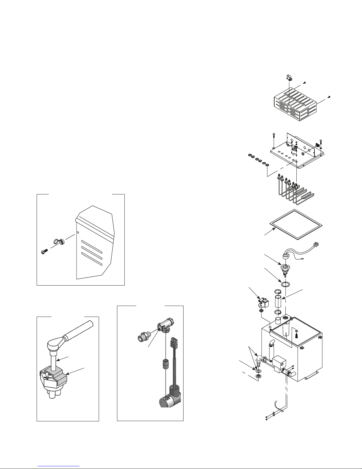
Enclosure Screw Cap
(Vapormist/Humidi-tech)
Note: Components may by oriented
differently than shown in drawing.
OM-778-3
Probe Tool
Torque probe assembly
to 10 ft-lbs (13.6 N-m).
3/8" drive
1
OM-7395X
mc_051508_1320
Fill Valve
3
Sediment screen (3)
inside of Tee
TANKASM-VM2-4X
Apply clear silicone (2) to both sides of gasket.
See Fill Valve inset.
Vapormist/Humidi-tech only
6
4
7
5
8
OM-768X
DRI-STEEM Vapormist/Humidi-tech/CRUV, Standard Water, Service Kit Manual • Page 3
Page 4

Vapormist/Humidi-tech/CRUV, standard water, service instructions
Inspection and maintenance
Cool down humidifier
Before performing service or maintenance procedures, allow
the tank to cool down. Insulated and uninsulated tanks will
have hot surfaces
Note: Fresh make‑up water is used to speed up cooling. Do
not close the manual water supply before cooling down
the humidifier; otherwise the tank could stay hot for
several hours.
1. Verify that there is no call for humidity and that the
aquastat set point (adjusted using the keypad/display Setup
screens) is less than room temperature (default setting
is 40 °F [4 °C]) so that the heaters do not energize while
cooling down the tank.
2. Verify that the tank is in Auto mode so it will fill after
draining begins.
3. Drain the tank:
a. Manually open the drain valve by moving the valve
lever located on the back of the drain valve to the
manual open position. The fill valve will open after
enough water has drained out of the tank.
b. Let the fill water run until the tank is cooled; then shut
off the field‑installed manual supply water shut‑off
valve.
c. Let the tank drain; then manually close the drain valve.
mc_052708_1145
Shut down humidifier
Follow the procedure below before performing service or
maintenance procedures (after the tank has cooled down and
drained):
1. If the humidifier is equipped with a Vapor‑logic3 controller,
use the keypad to change the control mode to Standby.
2. Shut off all electrical power to the humidifier using
the field‑installed fused disconnect, and lock all power
disconnect switches in the OFF position.
3. Close the field‑installed manual water supply shut‑off valve.
mc_060208_0945
Annually (also recommended when maintenance is performed)
1. All safety devices in the control circuit should be cycled on
and off to verify they are functioning. These include:
• Highlimitswitch
• Airflowprovingswitch
• Lowwaterlevelprobe.Pulloutprobeplug;fillvalve
should energize.
2. Measure current draw of heaters and verify amp values per
stage by comparing to the wiring diagram located inside
the subpanel cover. This identifies any burned out heaters.
Only qualified electrical personnel should perform this
task.
3. Inspect tank and gaskets for leaks.
mc_060208_1005
Seasonally (or as required, depending on water quality)
Clean the evaporating chamber. See the facing page of this
Service Kit manual for Vapormist instructions; see the back
page for CRUV instructions.
Off-season maintenance
Perform complete inspection and cleaning of the following:
• Heaters
• Proberods
• Skimmerportandwaterseal
• Humidifiertank
After cleaning, the humidifier should remain empty until
humidification is required.
mc_052708_1210
Note: Steps 4 and 7 below apply only to Vapormist humidifiers.
Off-season shut-down procedure
1. If the tank is hot, cool it down first. See cool‑down
instructions at left.
2. Drain evaporating chamber.
3. Switch off electrical power.
4. Remove enclosure.
5. Shut off water supply to makeup valve.
6. Examine the evaporating chamber (see facing page of this
Service Kit manual), and clean if necessary.
7. Replace enclosure.
8. Leave chamber dry, power off, and the water shut‑off valve
closed until the next humidification season.
mc_060208_1030
Page 4 • DRI-STEEM Vapormist/Humidi-tech/CRUV, Standard Water, Service Kit Manual
Page 5

Vapormist/Humidi-tech/CRUV, standard water, service instructions
Vapormist service
1. Remove the evaporating chamber:
a. Remove the two fasteners on each side of the cover
enclosure (see Enclosure Screw Cap inset on page 3)
b. Remove the enclosure.
WARNING!
Do not remove the humidifier electrical panel cover or the
heater terminal cover until electrical power is disconnected.
Contact with energized circuits can cause property damage,
severe personal injury or death as a result of electrical shock.
c. If the Vapormist has an SDU mounted directly above it,
the SDU cover must be removed before removing the
humidifier cover.
d. If the tank is hot, cool it down first (see cool‑down
instructions on facing page).
e. Shut off the water supply.
f. Allow the tank to drain completely.
g. Shut off the electrical supply.
h. Disconnect the fill line at the supply side of the fill
valve.
i. Disconnect the electrical plugs between the tank
components and the back of the electrical panel
(includes: power plug, fill plug, drain plug, water level
control plug, tank temperature sensor plug and thermal
trip plug).
Important: Disconnect by pulling on plug
housing. Do not disconnect by pulling on cord or
wires.
j. Disconnect the drain union on the back left corner of
the frame.
k. Disconnect the steam supply hose from the top of the
tank.
l. Lift the tank foot above the frame flange and slide the
tank assembly forward to remove.
2. Loosen the four cover bolts and remove the cover assembly
from the tank.
3. Clean the tank interior using a putty knife or similar flat
instrument.
4. Clean the probes:
a. Unplug probe plug assembly. Leave ground wire
connected to tank.
b. Unscrew the probe rod assembly using the probe tool
connected to a 3/8" square drive.
c. Inspect the probe housing and clean, ensuring that all
the housing passageways are clear. Remove the housing
from the holding bracket by sliding the housing
horizontally toward the open end of the bracket.
• Thescaleshouldflakeoffeasilyfromtheprobe
assembly rods.
• Thebottom3/8"(10mm)ofeachrodisthesensing
portion; clean these areas with a wire brush,
abrasive pad, or steel wool.
d. Inspect the composite plastic probe rod assembly for
any signs of cracking, roughness, or deterioration. If
found, replace probe assembly.
e. Reassemble and install the probe and probe plug
assembly. Verify ground wire is solidly connected to
tank.
5. Secure the chamber cover, making sure the cover gasket is
seated and the chamber is sealed.
6. Re‑install the evaporating chamber:
a. Reconnect the fill line.
b. Reconnect the electrical plugs (plugs are color coded).
c. Reconnect the drain union.
d. Reconnect the vapor hose.
7. Verify electrical connections:
a. Verify that all DIN rail‑mounted components are
securely fastened to DIN rail.
b. Verify that all power terminal screws and lugs are tight
from power block to heaters. See the table below for
torque specifications.
Table 5-1:
Vapormist torque specifications
Screw or lug location
Power block 16 1.8
Contactor 16 1.8
Heater
nut
Heater
wire lug
8-32 (8.5 mm) nut 20 2.2
10-32 (9.5 mm) nut 25 2.8
6 gauge (10 mm2) wire 35 4.0
8 gauge (6 mm2) wire 25 2.8
10-14 gauge (<6 mm2) wire 20 2.2
Torque
inch - lbs N-m
c. Verify that all plugs located under the humidifier cover
are completely plugged in.
8. Move the drain valve lever back to the auto position.
9. Turn on the water supply.
10. Turn on the electrical power.
mc_060208_1055
DRI-STEEM Vapormist/Humidi-tech/CRUV, Standard Water, Service Kit Manual • Page 5
Page 6

Vapormist/Humidi-tech/CRUV, standard water, service instructions
Humidifier De-scaling Solution
Scale buildup on humidifier heaters
acts as an insulator, reducing humidifier
performance while increasing energy
costs. To keep humidifiers operating as
efficiently as possible, remove scale with
DRI-STEEM's Humidifier De-scaling Solution,
available for purchase from your DRI-STEEM
representative or distributor.
The De-scaling Solution cleans without risk
of corroding humidifier tanks or welds. The
De-scaling Solution also cleans surfaces
unreachable by hand scraping.
DRI-STEEM's Humidifier De-scaling Solution
is the only approved cleaner/de-scaler for
use with DRI-STEEM humidifiers. Use of
other cleaners/de-scalers may void your
DRI-STEEM warranty.
mc_021908_1410-elec
DRI-STEEM Corporation
An ISO 9001: 2000 certified corporation
U.S. Headquarters:
14949 Technology Drive
Eden Prairie, MN 55344
800-328-4447 or 952-949-2415
952-229-3200 (fax)
European office:
Marc Briers
Grote Hellekensstraat 54 b
B-3520 Zonhoven
Belgium
+3211823595 (voice)
+3211817948 (fax)
E-mail: marc.briers@dristeem.com
Continuous product improvement is a
policy of DRI-STEEM Corporation; therefore,
product features and specifications are
subject to change without notice.
DRI-STEEM, Vapormist, Humidi-tech, CRUV,
and Vapor-logic are registered trademarks
of DRI-STEEM Corporation and are filed for
trademark registration in Canada and the
European community.
Drane-kooler is a trademark of DRI-STEEM
Corporation.
CRUV Service
1. Drain the tank. See Step 3 on page 4.
2. Clean the probes. See Step 4 on page 5.
3. Remove the tank cover and wet vac minerals out of tank
(recommended).
4. To remove tank for cleaning, disconnect drain line union, fill valve
supply line, electrical connections to drain, (disconnecting field
wiring in conduit is NOT recommended,) thermal trip, heaters,
fill valve, and probe. Disconnect steam hose from top of tank and
remove mounting bracket fasteners.
5. Remove evaporating chamber and clean.
6. Install the probe and probe plug assembly. Verify that ground wire is
connected.
7. Replace tank cover, making sure tank is sealed tight.
8. Reconnect drain line union, fill valve supply line, electrical
connections to drain, thermal trip, heaters, fill valve, and probe.
Connect steam hose to top of tank.
9. Verify drain valve lever is in AUTO position.
The CRUV humidifier is again ready to humidify.
mc_060208_1100
Mineral precipitate
As evaporation takes place in the humidifier, some of the minerals
dissolved in the water precipitate out and float on the water surface. The
minerals not removed by the skimmer will settle to the bottom of the
evaporating chamber.
Cleaning the evaporating chamber
The heating element is self‑cleaning. The mineral buildup on the element
flakes off after reaching a thickness of about 1/16" (2 mm), and settles to
the bottom of the chamber.
Long heater element life can be expected when the operation of the
humidifier is observed for a few weeks following initial start‑up. By
observing the mineral build‑up rate, the frequency of both drain/flush
use and manual cleaning can be determined and adjustments made.
CAUTION
Before this mineral scale builds up on the underside of the heating
element, it must be removed. Failure to do so could result in premature
heater burnout.
The humidifier is designed for convenient cleaning and maintenance.
mc_052708_1130
Start-up
Perform the Annual safety checks in the Inspection and maintenance
section on page 4.
If resuming operation after service, do not leave the humidifier
unattended; allow it to cycle through multiple fill cycles to verify that all
serviced parts are functioning properly. See the humidifier's Installation,
Operation, and Maintenance manual for start‑up details.
mc_052908_1005
© 2011 DRI-STEEM Corporation
Form No. VM/CRUV-standard-SKM-0711
Page 6 • DRI-STEEM Vapormist/Humidi-tech/CRUV, Standard Water, Service Kit Manual
Part No. 891000-001 Rev C
DRI-STEEM products are warranted according to the terms and conditions of the standard
two-year Limited Warranty effective when the humidifier was purchased. See the literature
that was shipped with the humidifier for warranty information.
mc_081308_1405
Page 7

Humidi-tech
®
et CRUV
®
Humidificateurs électriques,
Eau standard
Manuel du nécessaire d'entretien
ATTENTION
Indique une situation dangereuse qui pourrait entraîner des blessures
graves voire la mort si les consignes ne sont pas respectées.
ATTENTION
Lire l'ensemble des mises en garde et des instructions
Cette page fournit des consignes de sécurité importantes ; elle est conçue pour compléter — non remplacer — le Manuel d'installation,
d'utilisation et de maintenance (IOM). Lire l'IOM qui a été fourni avec l'humidificateur avant d'effectuer des interventions d'entretien ou de
maintenance sur n'importe quelle pièce du système. Le non-respect de l'ensemble des mises en garde et des instructions pourrait engendrer les
situations dangereuses décrites dans ce document et dans l'IOM, et occasionner des dommages aux biens, des préjudices corporels voire la mort.
Si l'IOM est manquant, rendez-vous à http://www.dristeem.com/ds_lit.jsp pour télécharger un manuel de remplacement.
Surfaces et eau portées à température élevée
Les systèmes d'humidification à vapeur comportent des surfaces à température extrêmement élevée ; la température de l'eau présente
dans les cuves, les cylindres à électrode, les conduites de vapeur et les ensembles de dispersion peut atteindre 100 °C. Pour éviter tout
risque de brûlures graves, laisser refroidir tout le système d'humidification.
Suivre la procédure de refroidissement décrite dans l'IOM de l'humidificateur avant d'effectuer des interventions d'entretien ou de
maintenance sur n'importe quelle pièce du système.
Arrêt de la source d'énergie
Avant toute intervention d'entretien ou de maintenance sur n'importe quelle pièce du système d'humidification, vérifier que toutes les
sources d'énergie sont à l'arrêt. Les sources d'énergie peuvent être des sources d'électricité, de gaz, de vapeur ou de liquide à température
élevée. Le fait de ne pas arrêter la source d'énergie peut occasionner une intoxication au monoxyde de carbone, un incendie, une explosion
ou un choc électrique, et faire naître d'autres situations dangereuses. Ces situations dangereuses pourraient occasionner des dommages
aux biens, des préjudices corporels, voire la mort.
Tout contact avec des circuits alimentés peut occasionner des dommages aux biens, des préjudices corporels graves voire la mort à la suite
d'un choc électrique ou d'un incendie. Ne pas retirer l'enveloppe/la protection, la porte/la protection du panneau électrique, les panneaux
d'accès ou le couvre-bornes de l'élément chauffant avant d'avoir débranché l'alimentation électrique.
Suivre la procédure d'arrêt décrite dans l'IOM de l'humidificateur avant d'effectuer des interventions d'entretien ou de maintenance sur
n'importe quelle pièce du système.
Risque de choc électrique
Si l'humidificateur démarre en réponse à une demande d'humidification lors d'une intervention de maintenance, cela pourrait occasionner
des préjudices corporels graves voire la mort à la suite d'un choc électrique. Pour éviter un tel démarrage, suivre la procédure ci-dessous
avant toute intervention d'entretien ou de maintenance sur cet humidificateur (une fois que la cuve a été refroidie et vidangée) :
1. Utiliser le pavé numérique Vapor-logic®3 ou Vapor-logic4 pour basculer le mode de commande en veille.
2. Couper toute l'alimentation électrique de l'humidificateur en utilisant le sectionneur à fusible installé sur site et verrouiller tous les
sectionneurs d'alimentation en position d'arrêt OFF.
3. Fermer les robinets de sectionnement d'alimentation manuelle en eau et en gaz installés sur site.
ATTENTION
Indique une situation dangereuse qui pourrait endommager ou détruire
des biens si les consignes ne sont pas respectées.
Dommages occasionnés par l'eau de refoulement à haute température
La température de l'eau de refoulement peut atteindre 212 °F et endommager la plomberie de vidange.
Si l'humidificateur est équipé d'un dispositif de tempérage de l'eau comme DRI-STEEM Drane-kooler™, il a besoin d'eau d'appoint fraîche pour
fonctionner correctement. S'assurer que l'alimentation en eau du Drane-kooler reste ouverte lors de la vidange.
Si l'humidificateur n'est pas équipé d'un dispositif de tempérage de l'eau, laisser la cuve refroidir avant d'ouvrir le robinet de vidange.
Les pièces citées dans ce nécessaire d'entretien sont prévues pour les humidificateurs HT99 et CRUV99 (août 1999 à ce jour).
ATTENTION
Les pièces sont répertoriées en page 2.
Page 8

Humidi-tech/CRUV, eau standard, pièces du nécessaire d'entretien
HT99 / CRUV99, eau standard, 2 à 4 kW
Nécessaire d'entretien n° 900100-001
N° Description de la pièce Référence. Qté.
1 Outil à sonde (voir l'encart Outil à sonde) 406201 1
2 Silicone, transparent (non représenté) 320000 1
3
Tamis à sédiments (voir l'encart Robinet de remplissage)
4 Joint d'étanchéité de protection 160695-001 1
5 Joint d'étanchéité de sonde 309750-004 1
6 Joint d'étanchéité de vidange Bulkhead (Humidi-tech
seulement)
7 Ensemble tige de sonde 406303-005 1
8 Carter de sonde 308500 1
HT99 / CRUV99, eau standard, 6 à 34 kW
Nécessaire d'entretien n° 900100-002
N° Description de la pièce Référence. Qté.
1 Outil à sonde (voir l'encart Outil à sonde) 406201 1
2 Silicone, transparent (non représenté) 320000 1
3
Tamis à sédiments (voir l'encart Robinet de remplissage)
4 Joint d'étanchéité de protection (Humidi-tech
seulement)
5 Joint d'étanchéité de sonde 309750-004 1
6 Joint d'étanchéité de drainage Bulkhead 309750-005 1
7 Ensemble tige de sonde 406303-006 1
8 Carter de sonde 308500 1
300051 1
309750-005 1
300051 1
160695-002 1
Page 8 • DRI-STEEM Humidi-tech/CRUV, eau standard, Manuel du nécessaire d'entretien
Page 9

Humidi-tech/CRUV, eau standard, pièces du nécessaire d'entretien
Le nécessaire d'entretien contient les pièces de rechange
référencées dans le schéma des pièces qui permettent à votre
humidificateur DRI‑STEEM de continuer à fonctionner au
maximum de ses performances. Ce Manuel du nécessaire
d'entretien fournit des consignes de sécurité et d'entretien
importantes ; il est conçu pour compléter — non remplacer — le
Manuel d'installation, d'utilisation et de maintenance (IOM).
Lire l'ensemble des mises en garde et des instructions en
page 1.
Lors des interventions d'entretien et de maintenance, remplacer
les pièces existantes par les pièces neuves fournies dans le
nécessaire d'entretien.
Capuchon vissé de
l'enceinte (Humidi-tech)
Remarque : Certains composants peuvent
être orientés différemment par
rapport au schéma.
OM-778-3
Outil à sonde
Embout mâle
de 3/8"
1
OM-7395X
Appliquer un couple de serrage de
13,6 N-m à la sonde.
Robinet de remplissage
3
Tamis à sédiments (3)
à l'intérieur du té
TANKASM-VM2-4X
4
7
Appliquer du silicone transparent
(2) aux deux faces du joint d'étanchéité.
Voir l'encart Robinet
de remplissage.
Humidi-tech seulement
5
6
8
OM-768X
DRI-STEEM Humidi-tech/CRUV, eau standard, Manuel du nécessaire d'entretien • Page 9
Page 10

Humidi-tech/CRUV, eau standard, consignes d'entretien
Inspection et maintenance
Refroidissement de l'humidificateur
Avant toute intervention d'entretien ou de maintenance, laisser
refroidir la cuve. Certaines surfaces des cuves isolées et non
isolées seront portées à température élevée
Remarque : De l'eau d'appoint fraîche est utilisée pour
accélérer le refroidissement. Ne pas fermer
l'alimentation manuelle en eau avant d'avoir
refroidi l'humidificateur ; autrement, la cuve
pourrait rester chaude pendant plusieurs heures.
1. Vérifier qu'il n'y a pas eu de demande d'humidification et
que le point de consigne de l'aquastat (réglé à l'aide du pavé
numérique ou des écrans de configuration de l'affichage) est
inférieur à la température ambiante (la valeur par défaut est
de 4 °C) afin que les éléments chauffants ne s'activent pas
lors du refroidissement de la cuve.
2. Vérifier que la cuve est en mode automatique de façon à ce
qu'elle se remplisse après le début de la vidange.
3. Vidange de la cuve :
a. Ouvrir manuellement le robinet de vidange en déplaçant
le levier situé à l'arrière du robinet de vidange en
position d'ouverture manuelle. Le robinet de remplissage
s'ouvrira dès qu'une quantité suffisante d'eau aura été
vidangée de la cuve.
b. Laisser couler l'eau de remplissage jusqu'à ce que la cuve
soit refroidie ; puis, fermer le robinet de sectionnement
de l'alimentation manuelle en eau installé sur site.
c. Laisser la cuve se vidanger ; puis, fermer manuellement
le robinet de vidange.
Arrêt de l'humidificateur
Suivre la procédure ci‑dessous avant toute intervention
d'entretien ou de maintenance (une fois que la cuve a été
refroidie et vidangée) :
1. Si l'humidificateur est équipé d'un dispositif de régulation
Vapor‑logic3, utiliser le pavé numérique pour basculer le
mode de commande en veille.
2. Couper toute l'alimentation électrique de l'humidificateur en
utilisant le sectionneur à fusible installé sur site et verrouiller
tous les sectionneurs d'alimentation en position d'arrêt OFF.
3. Fermer le robinet de sectionnement d'alimentation manuelle
en eau installé sur site.
Annuellement (également recommandé lors de la maintenance)
1.
Tous les dispositifs de sécurité du circuit de commande
doivent être mis en marche, puis arrêtés, afin de vérifier leur
fonctionnement. Ces dispositifs comprennent notamment :
• Commutateurdefindecourse
• Commutateurdecontrôlededébitd'air
• Sondedeniveaud'eaubas.Tirerlafichedelasonde;le
robinet de remplissage devrait s'activer.
2.
Mesurer le débit de courant des éléments chauffants et vérifier
les ampérages par étage par comparaison avec le schéma de
principe situé à l'intérieur de la protection du sous‑panneau.
Ceci permet d'identifier tous éléments chauffants grillés. Seul
le personnel qualifié en électricité peut effectuer cette tâche.
3. Inspecter la cuve et les joints d'étanchéité pour déceler des
fuites éventuelles.
À chaque saison (ou au besoin, selon la qualité de l'eau)
Nettoyer la chambre d'évaporation. Voir les instructions
relativesauHumidi-techsurlapageenregarddeceManuel
du nécessaire d'entretien ; voir les instructions relatives au
CRUV sur la page verso.
Maintenance de fin de saison
Effectuer une inspection et un nettoyage complets des
éléments suivants :
• Éléments chauffants
• Tiges de sonde
• Orifice de l'écumoire et siphon isolateur
• Cuve d'humidificateur
Après le nettoyage, l'humidificateur doit demeurer vide
jusqu'à ce qu'il y ait un besoin d'humidification.
Remarque : Les étapes 4 et 7 ci‑dessous s'appliquent
uniquementauxhumidificateursHumidi-tech.
Procédure d'arrêt hors saison
1. Si la température de la cuve est élevée, la refroidir au
préalable. Voir les instructions de refroidissement à gauche.
2. Vidanger la chambre d'évaporation.
3. Couper l'alimentation électrique.
4. Déposer l'enceinte.
5. Couper l'alimentation en eau au robinet d'appoint.
6.
Examiner la chambre d'évaporation (voir la page en regard de
ce Manuel du nécessaire d'entretien) et la nettoyer au besoin.
7. Remettre en place l'enceinte.
8. Laisser la chambre sèche, l'alimentation électrique coupée et
le robinet de sectionnement de l'alimentation en eau fermé
jusqu'à la prochaine saison d'humidification.
Page 10 • DRI-STEEM Humidi-tech/CRUV, eau standard, Manuel du nécessaire d'entretien
Page 11

Humidi-tech/CRUV, eau standard, consignes d'entretien
Entretien Humidi-tech
1. Déposer la chambre d'évaporation :
a. Retirerlesdeuxattachesdechaquecôtédel'enceintede
protection (voir l'encart Capuchon vissé de l'enceinte en
page 3)
b. Déposer l'enceinte.
ATTENTION
Ne pas retirer la protection du panneau électrique de l'humidificateur
ou le couvre-bornes de l'élément chauffant avant d'avoir débranché
l'alimentation électrique. Tout contact avec des circuits alimentés peut
occasionner des dommages aux biens, des préjudices corporels graves
voire la mort à la suite d'un choc électrique ou d'un incendie.
c. SileHumidi-techcomporteuneunitédedistribution
de l'espace (SDU) montée directement à l'aplomb, il
faut retirer la protection de la SDU avant de déposer la
protection de l'humidificateur.
d. Si la température de la cuve est élevée, la laisser refroidir
au préalable (voir les consignes de refroidissement sur la
page en regard).
e. Couper l'alimentation en eau.
f. Laisser la cuve se vidanger totalement.
g. Couper l'alimentation électrique.
h. Débrancherlaconduitederemplissageducôté
d'alimentation du robinet de remplissage.
i.
Débrancher les fiches électriques entre les éléments de la
cuve et l'arrière du panneau électrique (comprenant : fiche
d'alimentation, fiche de remplissage, fiche de vidange,
fiche de commande du niveau d'eau, fiche du capteur de
température de la cuve et fiche du déclencheur thermique).
Important: Débrancher en tirant sur le boîtier de la
fiche. Ne pas débrancher en tirant sur le cordon ou les fils.
j. Débrancher le raccord de vidange dans le coin arrière
gauche du châssis.
k. Débrancher le tuyau d'alimentation en vapeur du haut
de la cuve.
l.
Soulever le pied de la cuve au‑dessus de la bride du châssis
et faire coulisser la cuve vers l'avant pour déposer.
2. Desserrer les quatre boulons de la protection et déposer la
protection de la cuve.
3. Nettoyer l'intérieur de la cuve à l'aide d'un couteau à
mastiquer ou d'un instrument plat similaire.
4. Nettoyer les sondes :
a. Débrancher la fiche de la sonde. Laisser le fil de terre
connecté à la cuve.
b. Dévisser la tige de la sonde à l'aide de l'outil à sonde
connecté à une douille à embout mâle de 3/8".
c.
Inspecter le carter de la sonde et le nettoyer, en s'assurant
que toutes ses voies de passage sont dégagées. Retirer le
carter du support de maintien en faisant coulisser le carter
horizontalement vers l'extrémité ouverte du support.
•
Le tartre devrait se détacher aisément des tiges de sonde.
•
Les 10 mm du bas de chaque tige sont la partie
détectrice ; nettoyer cette partie à l'aide d'une brosse
métallique, d'un tampon abrasif ou de laine d'acier.
d. Inspecter la tige de sonde en plastique composite pour
déceler toute fissure, rugosité ou détérioration. Dans ce
cas, remplacer la sonde.
e.
Remonter et installer la sonde et la fiche de la sonde.
Vérifier que le fil de terre est solidement connecté à la cuve.
5. Fixer la protection de la chambre, en s'assurant que le joint
d'étanchéité de la protection est bien en place et la chambre
est fermée de façon étanche.
6. Réinstaller la chambre d'évaporation :
a. Reconnecter la conduite de remplissage.
b. Reconnecter les fiches électriques (les fiches sont
repérées par un code de couleur).
c. Reconnecter le raccord de vidange.
b. Reconnecter le tuyau à vapeur.
7. Vérifier les branchements électriques :
a. Vérifier que tous les composants montés sur guide DIN
sont solidement fixés au guide DIN.
b. Vérifier que toutes les vis et les cosses des bornes
d'alimentation sont serrées entre le bloc d'alimentation
et les éléments chauffants. Voir les spécifications de
couple de serrage dans le tableau ci‑dessous.
Tableau 11-1 :
Spécifications de couple de serrage
Humidi-tech
Emplacement de vis ou de
cosse
Bloc d'alimentation 1,8
Contacteur 1,8
Écrou
d'élément
chauffant
Cosse de fil
d'élément
chauffant
8,5 mm Écrou 2,2
9,5 mm Écrou 2,8
2
Fil 10 mm
2
Fil 6 mm
Fil < 6 mm
2
Couple de serrage
N-m
4,0
2,8
2,2
c. Vérifier que toutes les fiches situées sous la protection de
l'humidificateur sont enfoncées à fond.
8. Ramener le levier du robinet de vidange en position
automatique.
9. Ouvrir l'alimentation en eau.
10. Allumer l'alimentation électrique.
DRI-STEEM Humidi-tech/CRUV, eau standard, Manuel du nécessaire d'entretien • Page 11
Page 12

Humidi-tech/CRUV, eau standard, consignes d'entretien
Entretien CRUV
1. Vidanger la cuve. Voir l'étape 3 en page 4.
2. Nettoyer les sondes. Voir l'étape 4 en page 5.
3. Déposer la protection de la cuve et éliminer à l'aspirateur industriel
eaux et poussières les sels minéraux présents dans la cuve
(recommandé).
4. Pour déposer la cuve en vue du nettoyage, déconnecter le raccord
de la conduite de vidange, la conduite d'alimentation du robinet de
remplissage, les branchements électriques sur la vidange (il n'est PAS
recommandé de déconnecter le câblage sur site dans le conduit),
le déclencheur thermique, les éléments chauffants, le robinet de
remplissage et la sonde. Déconnecter le tuyau de vapeur au sommet
de la cuve et rétirer les attaches du support de montage.
5. Déposer la chambre d'évaporation et la nettoyer.
6. Installer la sonde et la fiche de la sonde. Vérifier que le fil de terre est
connecté.
7. Remettre en place la protection de la cuve, en s'assurant que la cuve
est fermée de façon étanche.
8. Reconnecter le raccord de la conduite de vidange, la conduite
d'alimentation du robinet de remplissage, les branchements
électriques sur la vidange, le déclencheur thermique, les éléments
chauffants, le robinet de remplissage et la sonde. Connecter le tuyau
de vapeur au sommet de la cuve.
9. Vérifier que le levier du robinet de vidange est en position AUTO.
DRI-STEEM Corporation
ISO 9001 : 2000 société certifiée
Bureau européen :
Marc Briers
Grote Hellekensstraat 54 b
B-3520 Zonhoven
Belgique
+3211823595 (téléphone)
+3211817948 (télécopie)
E-mail : marc.briers@dristeem.com
Siège social aux États-Unis :
14949 Technology Drive
Eden Prairie, MN 55344
800-328-4447 ou 952-949-2415
952-229-3200 (télécopie)
DRI-STEEM Corporation poursuit une politique
d'amélioration continue de ses produits. Par conséquent,
les caractéristiques et les spécifications des produits
peuvent changer sans préavis.
DRI-STEEM, Humidi-tech, CRUV et Vapor-logic sont des
marques déposées de DRI-STEEM Corporation et ont fait
l'objet d'une demande de dépôt de marque au Canada et
dans la Communauté Européenne.
Drane-kooler est une marque déposée de
DRI-STEEM Corporation.
© 2011 DRI-STEEM Corporation
L'humidificateur CRUV est prêt pour un nouveau cycle d'humidification.
Précipités minéraux
Au fur et à mesure qu'intervient l'évaporation dans l'humidificateur,
certains des sels minéraux dissous dans l'eau précipitent et flottent à la
surface de l'eau. Les sels minéraux qui ne sont pas éliminés par l'écumoire
se déposent au fond de la chambre d'évaporation.
Nettoyage de la chambre d'évaporation
L'élément chauffant se nettoie automatiquement. Les sels minéraux
accumulés sur l'élément se détachent après avoir atteint une épaisseur
d'environ 2 mm et se déposent au fond de la chambre.
On peut s'attendre à ce que l'élément chauffant ait une durée de vie
importante quand le fonctionnement de l'humidificateur est surveillé
pendant les quelques semaines qui suivent le démarrage initial. Surveiller
la vitesse d'accumulation des sels minéraux permet de déterminer à la fois
la fréquence des vidanges et rinçages et du nettoyage manuel et d'apporter
des ajustements.
ATTENTION
Le tartre doit être éliminé avant de commencer à s'accumuler au‑dessous
de l'élément chauffant. Le non‑respect de cette consigne pourrait
entraîner le grillage prématuré de l'élément chauffant.
L'humidificateur est conçu pour faciliter le nettoyage et la maintenance.
Démarrage
EffectuerlescontrôlesdesécuritéAnnuels prévus à la section Inspection
et maintenance en page 4.
En cas de reprise du fonctionnement après un entretien, ne pas laisser
l'humidificateur sans surveillance ; le laisser accomplir plusieurs cycles de
remplissage afin de vérifier que toutes les pièces entretenues fonctionnent
correctement. Voir les détails du démarrage dans le Manuel d'installation,
d'utilisation et de maintenance de l'humidificateur.
Formulaire n° VM/CRUV-standard-SKM-F-0711
Référence 891000-001 Rev C
Page 12 • DRI-STEEM Humidi-tech/CRUV, eau standard, Manuel du nécessaire d'entretien
Les produits DRI-STEEM sont garantis selon les modalités de la garantie limitée de deux ans
standard prenant effet à la date d'achat de l'humidificateur. Voir la documentation fournie avec
l'humidificateur pour plus d'informations sur la garantie.
Page 13

Humidi-tech
®
, and CRUV
®
Elektro-Befeuchter,
Normalwasser
Anleitung für Wartungskit
VORSICHT
Weist auf einen Betriebszustand hin, der zu schweren Verletzungen
oder Tod führen kann, falls die Anweisungen mißachtet werden.
Alle Warnhinweise und Arbeitsanweisungen lesen
Diese Seite enthält wichtige Sicherheitshinweise; sie ist als Zusatz zu verstehen und NICHT als Ersatz für die Installations- und
Bedienungsanleitung. Daher zuerst die Installations- und Bedienungsanleitung des Befeuchters lesen, welche mit dem Befeuchter geliefert
wurde, bevor jegliche Wartungsarbeiten am System durchgeführt werden. Nichteinhaltung dieser Warnhinweise kann zu den hier und in
der Befeuchter-Bedienungsanleitung beschriebenen gefährlichen Betriebszuständen führen, welche Sachschäden, Verletzungen oder Tod
zur Folge haben können.
Fehlt die Befeuchter-Bedienungsanleitung, diese von http://www.dristeem.com/ds_lit.jsp herunterladen.
Heiße Oberflächen und heißes Wasser
Dampf-Befeuchtungssysteme weisen sehr heiße Oberflächen auf und das Wasser in den Tanks, Elektrozylindern, Dampfrohren und
Verteilmodulen kann bis zu 100 °C heiß sein. Daher das gesamte Befeuchtersystem zuerst abkühlen um Verbrühungen zu vermeiden.
Das Abkühlverfahren in der Befeuchter-Bedienungsanleitung befolgen, bevor jegliche Wartungsarbeiten an Teilen des Systems erfolgen.
Die Energiezufuhr abschalten
Bevor jeglicher Wartung an Teilen des Befeuchtungssystems, sicherstellen, die gesamte Energiezufuhr ist abgeschaltet. Die
Energiequellen können, Strom, Gas, Dampf oder heißes Fluid sein. Nichteinhaltung dieser Anweisung kann zu Kohlenmonoxidvergiftung,
Feuer, Explosion, Stromschlag und anderen gefährlichen Betriebszuständen führen. Diese gefährlichen Betriebszustände können zu
Sachschäden, Verletzungen oder Tod führen.
Kontakt mit stromführenden Schaltkreisen kann zu Sachschäden, schweren Verletzungen oder Tod führen. Daher zuerst die Stromzufuhr
abschalten und aussperren, bevor jegliche Abdeckungen oder Schaltkästen geöffnet bzw. Arbeiten an Klemmen oder Elektrik
durchgeführt werden.
Die Anweisungen zur korrekten Abschaltung in der Befeuchter-Bedienungsanleitung befolgen, bevor jegliche Wartungsarbeiten an Teilen
des Systems erfolgen.
ACHTUNG
Weist auf einen Betriebszustand hin, der zu Sachschäden führen kann,
falls die Anweisungen mißachtet werden.
VORSICHT
Gefahr durch Stromschlag
Falls der Befeuchter während der Wartung einschaltet kann dies zu schweren Verletzungen oder Tod durch Stromschlag führen. Um
ein automatisches Einschalten zu verhindern, die nachfolgenden Anweisungen beachten, bevor jegliche Wartungsarbeiten an diesem
Befeuchter erfolgen (nachdem der Tank abgekühlt und entwässert wurde):
1. Mit Hilfe des Vapor-logic®3 oder Vapor-logic4 Steuergeräts in den Steuermodus Standby schalten.
2. Die Stromversorgung am bauseitigen gesicherten Hauptschalter abschalten und alle Schalter in Position AUS sperren.
3. Die bauseitigen manuellen Wasser- und Gaszufuhrventile schließen.
Schäden aufgrund heißem Abwasser
Abwasser kann bis zu 100 °C heiß sein und die Ablaufverrohrung beschädigen.
Ist der Befeuchter mit einem Abwasserkühlgerät wie z.B. dem DRI-STEEM Drane-kooler™ ausgerüstet muss ein Kaltwasseranschluss vorhanden sein,
damit das Gerät ordnungsgemäß funktioniert. Daher sicherstellen, die Wasserzufuhr zum Drane-kooler-Kühlgerät ist während des Abkühlvorgangs
geöffnet.
Weist der Befeuchter kein Abwasserkühlgerät auf, den Tank zuerst abkühlen lassen, bevor das Ablaufventil geöffnet wird.
Teile für diesen Wartungssatz passen zu Befeuchter, HT99 und CRUV99 (ab August 1999 bis heute). Für Teileliste siehe Seite 2.
ACHTUNG
Page 14

Humidi-tech/CRUV, Normalwasser, Wartungssatz-Teile
HT99 / CRUV99, Normalwasser, 2 bis 4 kW
Wartungssatz-Nr. 900100-001
Nr. Benennung Teile-Nr. Menge
1 Sondenwerkzeug (siehe Abbildung Sondenwerkzeug) 406201 1
2 Silikon, klar (nicht dargestellt) 320000 1
3 Filtereinsatz (siehe Abbildung Füllventil) 300051 1
4 Dichtung Abdeckung 160695-001 1
5 Dichtung Sonde 309750-004 1
6 Dichtung Trennwand-Ablauf (Nur Humidi-tech) 309750-005 1
7 Sondenbaugruppe 406303-005 1
8 Sondengehäuse 308500 1
HT99 / CRUV99, Normalwasser, 6 bis 34 kW
Wartungssatz-Nr. 900100-002
Nr. Benennung Teile-Nr. Menge
1 Sondenwerkzeug (siehe Abbildung Sondenwerkzeug) 406201 1
2 Silikon, klar (nicht dargestellt) 320000 1
3 Filtereinsatz (siehe Abbildung Füllventil) 300051 1
4 Dichtung Abdeckung (Nur Humidi-tech) 160695-002 1
5 Dichtung Sonde 309750-004 1
6 Dichtung Trennwand-Ablauf 309750-005 1
7 Sondenbaugruppe 406303-006 1
8 Sondengehäuse 308500 1
Seite 14 • DRI-STEEM Humidi-tech/CRUV, Normalwasser, Anleitung für Wartungssatz
Page 15

Humidi-tech/CRUV, Normalwasser, Wartungssatz-Teile
Dieser Wartungssatz enthält Ersatzteile gemäß den Angaben
der Teilezeichnung für einen optimalen Betrieb Ihres
DRI‑STEEM Befeuchters. Die vorliegende Anleitung enthält
wichtige Sicherheits‑ und Wartungsanweisungen und ist kein
Ersatz für die mit dem Befeuchter gelieferte Installations‑ und
Bedienungsanleitung. Bitte lesen Sie alle Warnhinweise und
Arbeitsanweisungen auf Seite 1.
Bei der Durchführung von Wartungsarbeiten die alten Teile mit
den neuen Teilen aus diesem Wartungssatz ersetzen.
Kappe Gehäuseschraube
(Humidi-tech)
Anmerkung: Bauteile können eine
unterschiedliche Ausrichtung
erfordern als hier dargestellt.
OM-778-3
Sondenwerkzeug
3/8" Einsatz
Anziehmoment für Sonden-
Baugruppe 13.6 Nm.
1
OM-7395X
Füllventil
3
Filtereinsatz (3)
im -T-Stück
TANKASM-VM2-4X
Klares Silikon (2) auf beiden Seiten der Dichtung
auftragen.
Siehe Einzelheit Füllventil.
Nur Humidi-tech
6
4
7
5
8
OM-768X
DRI-STEEM Humidi-tech/CRUV, Normalwasser, Anleitung für Wartungssatz • Seite 15
Page 16

Humidi-tech/CRUV, Normalwasser, Wartungsanweisungen
Inspektion und Wartung
Befeuchter abkühlen
Bevor jeglichen Wartungsarbeiten zuerst den Tank abkühlen
lassen. Wärmegedämmte und nicht gedämmte Tanks weisen
heiße Oberflächen auf.
Anmerkung: Zur Abkühlung ist frisches Zusatzwasser
erforderlich. Daher den Wasserzulauf erst sperren
nachdem der Befeuchter abgekühlt wurde.
Andernfalls bleibt der Tank noch für mehrere
Stunden heiß.
1. Sicherstellen, es wird keine Befeuchtung gefordert und der
Wasserthermostat‑Einstellwert liegt unter der aktuellen
Raumtemperatur(EinstellungmitHilfedesSteuergeräts
in Anzeige Setup, Vorgabeeinstellung ist 4 °C) damit die
HeizgerätenichteinschaltenwährendderTankabkühlt.
2. Sicherstellen der Tank ist in Modus Auto damit sich der
Tank wieder füllt, wenn die Entwässerung beginnt.
3. Den Tank entwässern:
a. Am Ablaufventil den Ventilhebel, der sich auf der
RückseitedesVentilsbefindet,vonHandindiePosition
'Manuell öffnen' schieben. Das Füllventil öffnet nachdem
eine gewisse Menge Wasser aus dem Tank ausgelaufen
ist.
b. Die Wasserzulaufleitung offen lassen, bis sich der
Tank ausreichend abgekühlt hat. Dann das bauseitig
installierte manuelle Absperrventil in der Zulaufleitung
schließen.
c. Den Tank entwässern lassen und danach das
AblaufventilvonHandschließen.
Befeuchter abschalten
Die nachfolgenden Anweisungen beachten bevor jegliche
Wartungsarbeiten ausgeführt werden (Nachdem der Tank
abgekühlt hat und entwässert ist):
1. Ist der Befeuchter mit einer Vapor‑logic3 Steuerung
ausgerüstet,mitHilfedesSteuergerätsdenBefeuchterin
Modus Standby schalten.
2. DiekompletteStromzufuhrzumBefeuchtermitHilfedes
bauseitigen Sicherungs‑Trennschalter sperren und alle
Stromtrennschalter in Position AUS sperren.
3. Das bauseitig installierte manuelle Absperrventil in der
Wasser‑Zulaufleitung schließen.
Jährlich (sowie nach Wartungsarbeiten)
1. Alle Sicherheitsgeräte im Steuerkreis sollten Ein/Aus
getaktet werden um deren ordnungsgemäße Funktion zu
prüfen. Diese umfassen:
• Maximal-Grenzwertschalter
• Luftströmungsschalter
• Wassermangel-Pegelsonde.DazudenSteckerander
Sonde abziehen; Das Füllventil sollte nun schalten.
2. DieStromaufnahmederHeizgerätemessenunddie
gemessenen Werte pro Stufe mit den Werten im Schaltplan,
der sich auf der Innenseite der Abdeckung befindet,
vergleichen.DamitlassensichausgebrannteHeizgeräte
erkennen. Diese Arbeit darf nur von einem qualifizierten
Elektriker durchgeführt werden.
3. Tank und Dichtungen auf Undichtheiten überprüfen.
Saisonal (oder wie erforderlich, abhängig von der
Wasserqualität)
Die Verdampfungskammer reinigen. Siehe
gegenüberliegendeSeiteindieserAnleitungfürHumidi-
tech Anweisungen; siehe Rückseite für CRUV Anweisungen.
Wartung außerhalb der Saison
Eine komplette Inspektion und Reinigung folgender Teile
durchführen:
• Heizgeräte
• Sondenstäbe
• SkimmeranschlussundWasserdichtung
• Befeuchtertank
Nach erfolgter Reinigung sollte der Befeuchter leer bleiben,
bis eine Befeuchtung erforderlich wird.
Anmerkung: Die nachfolgenden Schritte 4 und 7 gelten nur für
Humidi-techBefeuchter.
Stilllegung außerhalb der Saison
1. Ist der Tank noch heiß, die Anweisungen unter Befeuchter
Abkühlen in der linken Spalte beachten.
2. Die Verdampfungskammer entwässern.
3. Die Stromzufuhr abschalten.
4. Gehäuseabnehmen.
5. Wasserzulauf zum Zusatzwasserventil schließen.
6. Verdampfungskammer inspizieren (siehe gegenüberliegende
Seite dieser Anleitung), und falls erforderlich reinigen.
7. Gehäusewiedermontieren.
8. Bis zur nächsten Saison die Kammer trocken, den Strom
abgeschaltet und das Wasserabsperrventil geschlossen
lassen.
Seite 16 • DRI-STEEM Humidi-tech/CRUV, Normalwasser, Anleitung für Wartungssatz
Page 17

Humidi-tech/CRUV, Normalwasser, Wartungsanweisungen
Humidi-tech Wartung
1. Die Verdampfungskammer ausbauen:
a. Die zwei Schrauben auf jeder Seite der
Gehäuseabdeckunglösen(sieheEinzelheitKappe
GehäuseschraubenaufSeite3)
b. DasGehäuseabnehmen.
VORSICHT!
Die Abdeckungen der Schaltplatine und HeizgeräteKlemmenleiste am Befeuchter erst öffnen, nachdem die
Stromzufuhr ausgesperrt ist. Der Kontakt mit Schaltkreisen
kann zu Sachschäden, schweren Verletzungen oder Tod durch
Stromschlag führen.
c. IstdirektüberdemHumidi-tech-BefeuchtereinSDU-
Modul montiert, muss die SDU‑Abdeckung zuerst
abgenommen werden, bevor die Befeuchter‑Abdeckung
abgenommen werden kann.
d. Ist der Tank noch heiß, diesen zuerst abkühlen
(siehe Anweisungen zum Abkühlen auf der
gegenüberliegenden Seite).
e. Die Wasserzufuhr absperren.
f. Den Tank komplett entwässern.
g. Die Stromzufuhr aussperren.
h. Die Zulaufleitung auf der Zufuhrseite des Füllventils
trennen.
i. Die Elektrostecker zwischen den Tankkomponenten
und Rückseite der Platine abziehen (einschließlich:
Stromstecker, Füllstecker, Ablaufstecker,
Wasserstandregel‑Stecker, Tanktemperatursensor‑Stecker
und Thermoauslöser‑Stecker).
Wichtig: Den Stecker beim Abziehen am
Steckergehäuse halten und nicht am Kabel ziehen.
j. Die Ablaufverrohrung an der hinteren linken Ecke des
Rahmens lösen.
k. Den Dampfzufuhrschlauch von der Tankoberseite lösen.
l. Den Tankfuß über dem Rahmenflansch heben und
die Tank‑Baugruppe nach vorne ziehen um diese
herauszunehmen.
2. Die vier Schrauben der Abdeckung lösen und die
Abdeckung vom Tank abnehmen.
3. Die Tankinnenseite mit einem Kittmesser oder ähnlich
flachem Werkzeug reinigen.
4. Die Sonden reinigen:
a. Die Sondenstecker‑Baugruppe abziehen. Den
Erdungsdraht dabei nicht vom Tank lösen.
b. DieSondenstab-BaugruppemitHilfedesSonden-
werkzeugs und einer 3/8" Einatz‑Verlängerung lösen.
c. Das Sondengehäuse inspizieren und reinigen, dabei
darauf achten, dass alle Durchgänge frei sind. Das
GehäusehorizontalRichtungoffeneSeitederHalterung
ziehen und herausnehmen.
• DerKesselsteinsolltesichleichtvonden
Sondenstäben lösen.
• Dieunteren10mmjedenStabssindderSensorteil;
diesen Bereich jeweils mit einer Stahlbürste,
Scheuerpad oder Stahlwolle reinigen.
d. Den Verbundkunststoffteil der Sondenstäbe auf Risse,
raue Oberflächen oder Verwitterung prüfen und wenn
vorhanden, Sondenbaugruppe ersetzen.
e. Die Sonde und Sondenstecker‑Baugruppe wieder
montieren. Sicherstellen der Erdungsdraht ist fest mit
dem Tank verbunden.
5. Die Kammerabdeckung montieren und dabei sicherstellen,
die Dichtung der Abdeckung sitzt ordnungsgemäß und die
Kammer ist dicht.
6. Die Verdampfungskammer wieder einbauen:
a. Zulaufleitung wieder anschließen.
b. Elektrostecker wieder einstecken (Stecker sind
farbkodiert).
c. Ablaufverschraubung wieder anschließen.
d. Dampfschlauch wieder anschließen.
7. Alle Elektroanschlüsse überprüfen:
a. Sicherstellen alle Komponenten auf der DIN‑Schiene
sind sicher befestigt.
b. Sicherstellen die Klemmenschrauben der Klemmleiste
zudenHeizgerätensindfestgezogen.Siehenachstehende
Tabelle für korrekte Anziehmomente.
Tabelle 17-1:
Humidi-tech Anziehmomente
Schrauben oder Klemmenpunkt
Stromleiste 1,8
Schütz 1,8
Heiz-
gerät
Mutter
Heizgerät
Drahtklemme
8.5 mm Mutter 2,2
9.5 mm Mutter 2,8
10 mm2 Draht 4,0
6 mm2 Draht 2,8
<6 mm2 Draht 2,2
Anziehmoment
Nm
c. Sicherstellen, alle Stecker unter der Befeuchterabdeckung
sind komplett eingesteckt.
8. DenHebelamAblaufventilzurückaufPositionAutostellen.
9. Die Wasserzufuhr öffnen.
10. Die Stromversorgung einschalten.
DRI-STEEM Humidi-tech/CRUV, Normalwasser, Anleitung für Wartungssatz • Seite 17
Page 18

Humidi-tech/CRUV, Normalwasser, Wartungsanweisungen
CRUV Wartung
1. Tank entwässern. Siehe Schritt 3 auf Seite 4.
2. Die Sonden reinigen. Siehe Schritt 4 auf Seite 5.
3. Die Tankabdeckung abnehmen und die Mineralien mit einem geeigneten
Staubsauger aus dem Tank entfernen (empfohlen).
4. Um den Tank zur Reinigung auszubauen, die Ablaufrohrverschraubung,
Füllventil‑Zulaufleitung, Elektroverbindungen zum Ablauf, (lösen der
bauseitigenVerdrahtungimKanalistNICHTempfohlen)Thermoauslöser,
Heizgeräte,FüllventilundSondelösen.DenDampfschlauchvonder
TankoberseitelösenundBefestigungenderHalterungausbauen.
5. Verdampfungskammer herausnehmen und reinigen.
6. Die Sonden‑ und Sondenstecker‑Baugruppe montieren. Sicherstellen der
Erdungsdraht ist angeschlossen.
7. Tankabdeckung montieren und sicherstellen der Tank ist dicht.
8. Die Ablaufverrohrung, Füllventil‑Zulaufleitung, Elektroverbindungen
zumAblauf,Thermoauslöser,Heizgeräte,FüllventilundSondewieder
montieren. Den Dampfschlauch zur Tankoberseite verbinden.
9. Sicherstellen,derHebelamAblaufventilstehtaufPositionAUTO.
Der CRUV‑Befeuchter ist wieder einsatzbereit.
DRI-STEEM Corporation
Zertifiziert gemäß ISO 9001: 2000
Europaniederlassung:
Marc Briers
Grote Hellekensstraat 54 b
B-3520 Zonhoven
Belgien
+3211823595 (Tel)
+3211817948 (Fax)
E-mail: marc.briers@dristeem.com
US-Hauptsitz:
14949 Technology Drive
Eden Prairie, MN 55344
+1 800-328-4447 oder +1 952-949-2415
+1 952-229-3200 (Fax)
DRI-STEEM Corporation praktiziert eine
fortwährende Produktentwicklung; deshalb behalten
wir uns Produktänderungen ohne Vorankündigung
vor.
DRI-STEEM, Humidi-tech, CRUV und Vapor-logic
sind eingetragene Warenzeichen von DRI-STEEM
Corporation und als eingetragene Warenzeichen in
Kanada und der EU beantragt.
Drane-kooler ist ein Warenzeichen von
DRI-STEEM Corporation.
Salzablagerungen
Bei der Verdampfung im Befeuchter lösen sich eine gewisse Menge Salze, die
dann auf der Wasseroberfläche schwimmen. Salze welche nicht abgeschöpft
werden sinken zum Boden der Verdampfungskammer.
Reinigung der Verdampfungskammer
DasHeizelementistselbstreinigend.DieKesselsteinablagerungenbröckelnab,
wenn sie eine Dicke von 2 mm erreichen und setzen sich am Kammerboden ab.
UmdieStandzeitdesHeizelementeszuverlängernsolltederBefeuchterbetrieb
nach der ersten Inbetriebnahme über einige Wochen beobachtet werden.
Durch die Beobachtung der Kesselstein‑Ablagerungsrate kann die Frequenz
der Entwässerungs‑/ Spültakte und die manuelle Reinigung bestimmt und
optimiert werden.
ACHTUNG
BevorKesselsteinablagerungenaufdieUnterseitedesHeizelementes
heranreichen, müssen diese entfernt werden. Nichteinhaltung dieser Anweisung
kannzueinemvorzeitigenVersagenderHeizelementeführen.
Der Befeuchter ist für eine einfache Reinigung und Wartung ausgelegt.
Inbetriebnahme
Zuerst die jährlichen Sicherheitsprüfungen in Abschnitt Inspektion und
Wartung auf Seite 4 durchführen.
Nach erfolgter Wartung muss der Befeuchter über mehrere Fülltakte
überwacht werden, um sicherzustellen, alle gewarteten Teile funktionieren
ordnungsgemäß. Siehe auch Abschnitt Inbetriebnahme in der Befeuchter‑
Installations‑ und Bedienungsanleitung.
© 2011 DRI-STEEM Corporation
Form Nr. VM/CRUV-standard-SKM-G-0711
Teile-Nr. 891000-001 Rev C
Seite 18 • DRI-STEEM Humidi-tech/CRUV, Normalwasser, Anleitung für Wartungssatz
DRI-STEEM Produkte sind garantiert für einen Zeitraum von zwei Jahren ab dem Kaufdatum
entsprechend den Konditionen der zweijährigen begrenzten Gewährleistung. Siehe mit dem Befeuchter
gelieferte Literatur für Einzelheiten zur Gewährleistung.
 Loading...