

Page 1

READ AND SAVE THESE INSTRUCTIONS
®
GTS
Gas-to-Steam Humidifier
Installation, Operation,
and Maintenance Manual
WARNING
Fire or explosion hazard
If the information in this manual is not
followed exactly, a fi re or explosion could
result, causing property damage, personal
injury, or death.
If you smell gas:
• Do not try to light any appliance.
• Do not touch any electrical switch; do
not use any phone in your building.
• Immediately call your gas supplier
from an off-site phone. Follow the gas
supplier’s instructions.
• If you cannot reach your gas supplier,
call the fi re department.
Installation and service must be performed
by a qualifi ed installer, service agency, or
the gas supplier.
For toll-free support call DriSteem Technical
Support: 1-800-328-4447
Page 2
WARNINGS AND CAUTIONS
Warnings and cautions
EUROPEAN MODELS
SAFE OPERATING INSTRUCTIONS
1. Read “Fire and explosion hazard” on the next page.
2. Set the humidistat to the lowest setting.
3. Turn off all electric power to the appliance.
4. This appliance is equipped with an ignition device that automatically lights
the burner. Do not try to light the burner by hand.
5. Remove the control access panel.
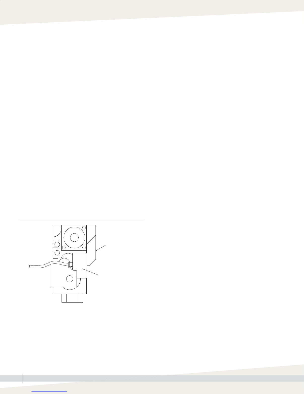
6. Unplug the black power plug on the gas valve (see detail of gas valve
below).
7. Wait five minutes to clear out any gas.
If you still smell gas, STOP! Follow “B” on the next page.
If you do not smell gas, go to the next step.
8. Plug the black power plug back into the gas valve.
9. Replace the control access panel.
10. Turn on electric power to the appliance.
11. Set the humidistat to desired setting.
12. If the appliance does not operate, follow the instructions below under,
“To turn off gas to appliance,” and call your service technician or gas
supplier.
Important: Troubleshooting information
for this humidifi er is located in the Vapor-logic
Installation and Operation Manual shipped
with your humidifi er. If you do not have this
manual, go to www.dristeem.com to download
or order a copy.
European models
The DriSteem GTS Gas-to-Steam Humidifi er has
been certifi ed for compliance with harmonised
European directives concerning gas
appliances, low voltage, and emission (Gas
Appliance Directive 90/396/CEE). Testing
was carried out by the Canadian Standards
Association; the notifying body is AFNOR in
France, which is a recognized authority by
the European bodies and the DTI in the United
Kingdom.
Installation must conform to the requirements
of the National Gas Safety (Installation & Use)
Regulations.
SAFE OPERATING INSTRUCTIONS
DETAIL OF GAS VALVE
Top view
Gas valve
Gas valve power plug
To turn off gas to appliance:
1. Set the humidistat to lowest setting.
2. Turn off all electric power to the appliance if service is to be performed.
3. Remove control access panel.
4. Unplug the black power plug on the gas valve.
5. Replace control access panel.
GTS INSTALLATION, OPERATION, AND MAINTENANCE MANUAL
ii
Page 3
Warnings and cautions
WARNING
Indicates a hazardous situation that could result in death or
serious personal injury if instructions are not followed.
mc_051508_1145
WARNING
Fire or explosion hazard
A. This appliance does not have a pilot. It is equipped with an ignition device which automatically lights the burner.
Do NOT try to light the burner by hand.
B. Before operating, smell all around the appliance area for gas. Be sure to smell next to the fl oor because gas can be
heavier than air and settle on the fl oor.
If you smell gas:
• Do not try to light any appliance.
• Do not touch any electrical switch; do not use any phone in your building.
• Immediately call your gas supplier from an off-site phone. Follow the gas supplier’s instructions.
• If you cannot reach your gas supplier, call the fi re department.
C. Do not use this appliance if any part has been under water. Immediately call a qualifi ed gas appliance service
technician to inspect the appliance and to replace any part of the control system and any gas control that has been
under water.
CAUTION
Indicates a hazardous situation that could result in damage to or
destruction of property if instructions are not followed.
Attention installer
Read this manual before installing, and leave this manual with product owner. This product must be installed by qualifi ed
HVAC and electrical contractors. Installation must be code approved. Improper installation can cause property damage,
severe personal injury, or death as a result of electric shock, burns, or fi re.
DriSteem
North America: 800-328-4447
Europe: +3211823595
Read all warnings and instructions
Read this manual before performing service or maintenance procedures on any part of the system. Failure to follow all
warnings and instructions could produce the hazardous situations described, resulting in property damage, personal
injury, or death.
Failure to follow the instructions in this manual can cause moisture to accumulate, which can cause bacteria and mold
growth or dripping water into building spaces. Dripping water can cause property damage; bacteria and mold growth
can cause illness.
®
Technical Support:
Continued
GTS INSTALLATION, OPERATION, AND MAINTENANCE MANUAL
iii
Page 4
Warnings and cautions
WARNING
Carbon monoxide, fi re, explosion, and electrical shock hazards
Improper installation, adjustment, alteration, service, maintenance, or use can cause carbon monoxide poisoning, fi re,
explosion, electrical shock, and other hazardous conditions. These hazardous conditions could cause personal injury,
property damage, or death. To prevent hazardous conditions, read all warnings; lock all power disconnect switches
in the OFF position before removing any access panels; and consult a qualifi ed installer, service agency, local gas
supplier, or your distributor or branch for information or assistance. The qualifi ed installer or agency must use only
factory authorized and listed kits or accessories when modifying this product.
• Inspect humidifi er and accessories upon arrival for damaged, missing, or improper parts. If there is a problem, call
DriSteem.
• Application of this humidifi er should have special attention given to vent sizing and material, gas input rate, and
unit sizing. Improper installation or misapplication of the humidifi er can cause excessive servicing or permanent
component failure.
• When working on equipment, observe precautions in literature, tags, and labels attached to or shipped with the unit
and observe other safety precautions that may apply. Wear safety glasses and work gloves. Have a fi re extinguisher
available during start-up, adjustment procedures, and service calls.
• Do not lift humidifi er by gas controls, gas manifold, fi re box, or shroud.
• Should overheating occur, or the gas supply fail to shut off, shut off the manual gas valve to the appliance before
shutting off the electrical supply.
• The evaporating chamber is designed as a nonpressurized vessel. DO NOT restrict piping where steam exits the
humidifi er. Install drain piping and piping that connects the evaporating chamber to the dispersion assembly only as
described in this manual. DO NOT install a shut-off valve on the piping connecting the evaporating chamber to the
steam outlet.
• Check the humidifi er name plate for the gas type indicated (natural gas or propane gas). Supply the humidifi er only
with the gas type indicated, or burner failure will result. To convert the humidifi er to a different gas type, contact
DriSteem Technical Support or your local DriSteem Representative/Distributor.
• Installation must conform to the requirements of the authority having jurisdiction or, in the absence of such
requirements, must conform to:
– In the United States: The National Fuel Gas Code, ANSI Z223.1 (latest edition).
– In Canada: Local plumbing or waste water codes and other applicable codes and with the current code CAN/
CGA-B149.1, “Installation Code for Natural Gas Burning Appliances and Equipment,” or CAN/CGA-B149.2,
“Installation Code for Propane Burning Appliances and Equipment.”
– In Europe: The National Gas Safety (Installation & Use) Regulations.
• Do not install in potentially explosive or fl ammable atmospheres laden with grain dust, sawdust, or similar airborne
materials.
• Installation of humidifi er in high humidity or salt water atmospheres causes accelerated corrosion, reducing the
normal life-span of the unit.
• To prevent premature heat exchanger failure, do not locate any gas-fi red unit in areas where chlorinated,
halogenated, or acid vapors are present in the atmosphere.
• Locate the humidifi er in an area clear of combustible materials, gasoline, and other fl ammable vapors and liquids.
Continued
GTS INSTALLATION, OPERATION, AND MAINTENANCE MANUAL
iv
Page 5
Warnings and cautions
WARNING
Carbon monoxide, fi re, explosion, and electrical shock hazards (continued)
• With the exception of sealed combustion units, do not locate units in tightly sealed rooms or small compartments
without provision for adequate combustion air and venting. Room air combustion must be supplied through a
minimum of two permanent openings in the wall, with at least one near the bottom. See "Combustion and ventilation
air" for additional information.
• Remove all shipping brackets and materials before operating the humidifi er.
• Do not locate humidifi er in a negative pressure space. Combustion products could be suctioned from the venting.
• Humidifi er fl ue gases must be vented to the outside atmosphere.
• Power supply disconnect switch must be in the off position while making wiring connections to prevent electrical
shock and equipment damage. All units must be wired in strict accordance with the wiring diagrams furnished with
this unit.
• Turn off all gas while installing the gas piping and manual shutoff valve for the humidifi er.
• The appliance and its individual shut-off valve must be disconnected from the gas supply piping system during any
pressure testing of that system at test pressures exceeding 0.5 psig (3.5 kPa).
Hot surfaces and hot water
This steam humidifi cation system has extremely hot surfaces. Water in tank, steam tubing, and dispersion assemblies can
be as hot as 212 °F (100 °C). Discharged steam is not visible. Contact with hot surfaces, discharged hot water, or air
into which steam has been discharged can cause severe personal injury. To avoid severe burns, follow the cool-down
procedure in this manual before performing service or maintenance procedures on any part of the system.
Disconnect electrical power
Disconnect electrical power before installing supply wiring or performing service or maintenance procedures on any
part of the humidifi cation system. Failure to disconnect electrical power could result in fi re, electrical shock, and other
hazardous conditions. These hazardous conditions could cause property damage, personal injury, or death.
Follow the shutdown procedure on Page 54 before performing service or maintenance procedures on any part of the
system.
CAUTION
Hot discharge water
Discharge water can be as hot as 212 °F (100 °C) and can damage some drain plumbing.
The DriSteem Drane-kooler
supply to the Drane-kooler remains open during draining.
Excessive supply water pressure
Supply water pressure greater than 80 psi (550 kPa) can cause the humidifi er to overfl ow.
™
water tempering device needs fresh make-up water in order to function properly. Make sure the water
GTS INSTALLATION, OPERATION, AND MAINTENANCE MANUAL
v
Page 6

Table of contents
WARNINGS AND CAUTIONS . . . . . . . . . . . . . . . . . . . . . . . . . . . . . . . . . . . . . . . . . . . . . . . . . . .ii
EUROPEAN MODELS. . . . . . . . . . . . . . . . . . . . . . . . . . . . . . . . . . . . . . . . . . . . . . . . . . . . . . . . . . ii
SAFE OPERATING INSTRUCTIONS . . . . . . . . . . . . . . . . . . . . . . . . . . . . . . . . . . . . . . . . . . . . . . . . ii
PRODUCT OVERVIEW . . . . . . . . . . . . . . . . . . . . . . . . . . . . . . . . . . . . . . . . . . . . . . . . . . . . . . . . .2
Tap/softened water . . . . . . . . . . . . . . . . . . . . . . . . . . . . . . . . . . . . 2
RO/DI water option . . . . . . . . . . . . . . . . . . . . . . . . . . . . . . . . . . . . 3
SPECIFICATIONS. . . . . . . . . . . . . . . . . . . . . . . . . . . . . . . . . . . . . . . . . . . . . . . . . . . . . . . . . . . . .4
Models, capacities, electrical specifications, and weights . . . . . . . . . . . . 4
Dimensions . . . . . . . . . . . . . . . . . . . . . . . . . . . . . . . . . . . . . . . . . . . . . 5
INSTALLATION . . . . . . . . . . . . . . . . . . . . . . . . . . . . . . . . . . . . . . . . . . . . . . . . . . . . . . . . . . . . . .6
Location and clearance recommendations . . . . . . . . . . . . . . . . . . . . . . . 6
Outdoor Enclosure: . . . . . . . . . . . . . . . . . . . . . . . . . . . . . . . . . . . . . . . 7
Mounting . . . . . . . . . . . . . . . . . . . . . . . . . . . . . . . . . . . . . . . . . . . 7
Operation . . . . . . . . . . . . . . . . . . . . . . . . . . . . . . . . . . . . . . . . . . 14
Wiring . . . . . . . . . . . . . . . . . . . . . . . . . . . . . . . . . . . . . . . . . . . . . . . 15
Piping: . . . . . . . . . . . . . . . . . . . . . . . . . . . . . . . . . . . . . . . . . . . . . . . 16
Tap/softened water . . . . . . . . . . . . . . . . . . . . . . . . . . . . . . . . . . . 16
RO/DI water option . . . . . . . . . . . . . . . . . . . . . . . . . . . . . . . . . . . 17
Supply water and drain overflow connections . . . . . . . . . . . . . . . . . 18
Supply water . . . . . . . . . . . . . . . . . . . . . . . . . . . . . . . . . . . . . . . . 19
Drain . . . . . . . . . . . . . . . . . . . . . . . . . . . . . . . . . . . . . . . . . . . . . 21
Gas . . . . . . . . . . . . . . . . . . . . . . . . . . . . . . . . . . . . . . . . . . . . . . 22
Combustion and ventilation air . . . . . . . . . . . . . . . . . . . . . . . . . . . . . . 26
Room air combustion . . . . . . . . . . . . . . . . . . . . . . . . . . . . . . . . . . 26
Sealed combustion . . . . . . . . . . . . . . . . . . . . . . . . . . . . . . . . . . . . 27
Vertical and horizontal venting . . . . . . . . . . . . . . . . . . . . . . . . . . . . . . 28
Guidelines (stack connection) . . . . . . . . . . . . . . . . . . . . . . . . . . . . 28
Special horizontal venting requirements . . . . . . . . . . . . . . . . . . . . . 30
Dispersion: . . . . . . . . . . . . . . . . . . . . . . . . . . . . . . . . . . . . . . . . . . . . 31
Selecting a location . . . . . . . . . . . . . . . . . . . . . . . . . . . . . . . . . . . 31
Interconnecting piping requirements . . . . . . . . . . . . . . . . . . . . . . . . 32
Steam outlet connections . . . . . . . . . . . . . . . . . . . . . . . . . . . . . . . 34
Drip tee installation . . . . . . . . . . . . . . . . . . . . . . . . . . . . . . . . . . . 35
Single tube and multiple tube . . . . . . . . . . . . . . . . . . . . . . . . . . . . 36
Rapid-sorb . . . . . . . . . . . . . . . . . . . . . . . . . . . . . . . . . . . . . . . . . 41
Area-type fan . . . . . . . . . . . . . . . . . . . . . . . . . . . . . . . . . . . . . . . 48
Ultra-sorb . . . . . . . . . . . . . . . . . . . . . . . . . . . . . . . . . . . . . . . . . . 49
GTS INSTALLATION, OPERATION, AND MAINTENANCE MANUAL
vi
Page 7

Table of contents
OPERATION . . . . . . . . . . . . . . . . . . . . . . . . . . . . . . . . . . . . . . . . . . . . . . . . . . . . . . . . . . . . . .
50
Start-up . . . . . . . . . . . . . . . . . . . . . . . . . . . . . . . . . . . . . . . . . . . . . . 50
Start-up checklist . . . . . . . . . . . . . . . . . . . . . . . . . . . . . . . . . . . . . 50
Start-up procedure . . . . . . . . . . . . . . . . . . . . . . . . . . . . . . . . . . . . 51
Start-up commissioning checklist . . . . . . . . . . . . . . . . . . . . . . . . . . . . . 52
MAINTENANCE . . . . . . . . . . . . . . . . . . . . . . . . . . . . . . . . . . . . . . . . . . . . . . . . . . . . . . . . . . . 54
Inspection recommendations . . . . . . . . . . . . . . . . . . . . . . . . . . . . . . . . 54
MAINTENANCE . . . . . . . . . . . . . . . . . . . . . . . . . . . . . . . . . . . . . . . . . . . . . . . . . . . . . . . . . . . 55
Burners . . . . . . . . . . . . . . . . . . . . . . . . . . . . . . . . . . . . . . . . . . . . . . . 56
Burner assemblies and heat exchanger tubes . . . . . . . . . . . . . . . . . 56
Maintenance frequency . . . . . . . . . . . . . . . . . . . . . . . . . . . . . . . . 56
Burner maintenance instructions . . . . . . . . . . . . . . . . . . . . . . . . . . . 56
Tap/softened water . . . . . . . . . . . . . . . . . . . . . . . . . . . . . . . . . . . . . . 57
Water quality recommendations . . . . . . . . . . . . . . . . . . . . . . . . . . 57
Adjusting skim duration . . . . . . . . . . . . . . . . . . . . . . . . . . . . . . . . 57
Cool down procedure . . . . . . . . . . . . . . . . . . . . . . . . . . . . . . . . . 58
Inspection and maintenance . . . . . . . . . . . . . . . . . . . . . . . . . . . . 59
RO/DI water option . . . . . . . . . . . . . . . . . . . . . . . . . . . . . . . . . . . . . . 61
RO/DI water quality recommendations . . . . . . . . . . . . . . . . . . . . . 61
Cool down procedure . . . . . . . . . . . . . . . . . . . . . . . . . . . . . . . . . 62
Inspection . . . . . . . . . . . . . . . . . . . . . . . . . . . . . . . . . . . . . . . . . . 63
REPLACEMENT PARTS . . . . . . . . . . . . . . . . . . . . . . . . . . . . . . . . . . . . . . . . . . . . . . . . . . . . . . . 64
GTS humidifier . . . . . . . . . . . . . . . . . . . . . . . . . . . . . . . . . . . . . . . . . 64
Fill, drain, and blocked flue sensor . . . . . . . . . . . . . . . . . . . . . . . . . . . 66
Electrical parts . . . . . . . . . . . . . . . . . . . . . . . . . . . . . . . . . . . . . . . . . 68
Outdoor Enclosure . . . . . . . . . . . . . . . . . . . . . . . . . . . . . . . . . . . . . . . 70
EUROPEAN MODELS. . . . . . . . . . . . . . . . . . . . . . . . . . . . . . . . . . . . . . . . . . . . . . . . . . . . . . . . 72
Authorized countries of destination . . . . . . . . . . . . . . . . . . . . . . . . 72
Appliance category . . . . . . . . . . . . . . . . . . . . . . . . . . . . . . . . . . . 72
WARRANTY . . . . . . . . . . . . . . . . . . . . . . . . . . . . . . . . . . . . . . . . . . . . . . . . . . . . . . . . . . . . . . 74
ATTENTION INSTALLER
Read this manual before installing. Leave
manual with product owner.
DriSteem Technical Support
800-328-4447
Where to find more information
On our Web site:
The following related documents can be
viewed, printed or ordered from our web site,
www.dristeem.com
• Catalogs:
– GTS
– Ultra-sorb
• Installation, Operation, and Maintenance
– Ultra-sorb
– Vapor-logic® (includes sensor placement
• DriSteem Design Guide (includes steam
In DriCalc:
DriCalc® is our humidifi cation system sizing
and selection software, which can be ordered
from our website.
DriCalc includes a comprehensive library of
installation guide documents, including:
• Rapid-sorb installation instructions for vertical
• Recommended dispersion placement within a
• Recommended sensor placement
®
®
manuals:
recommendations and troubleshooting
information)
loss tables and general humidifi cation
information)
airfl ows
duct or air handler
Or call us at 800-328-4447
While obtaining documents from our web site
or from DriCalc is the quickest way to review
our literature, we will also mail to you any
literature you need.
GTS INSTALLATION, OPERATION, AND MAINTENANCE MANUAL
1
Page 8
R
w
.
w
.
PRODUCT OVERVIEW
Product overview
GTS humidifi ers burn either natural or propane gas to heat fi ll water into steam
for humidifi cation. The unit has from one to four burners that fi re into a heat
exchanger submerged in a tank of water. When there is a call for humidity, the
burners fi re and generate steam until the call for humidity ends.
TAP/SOFTENED WATE
In tap/softened water GTS humidifi ers, a conductivity probe (see Figure 3-2)
monitors water level, requiring water conductivity to be at least 100 μS/cm to
operate properly. Therefore, GTS tap/softened water models do not operate
ith RO/DI water (water that has been treated using reverse osmosis or
deionized water). For operation with RO/DI water, see “RO/DI water option”
on the next page
Note: GTS humidifi ers for tap/softened water can be converted in the fi eld
ith the RO/DI water option
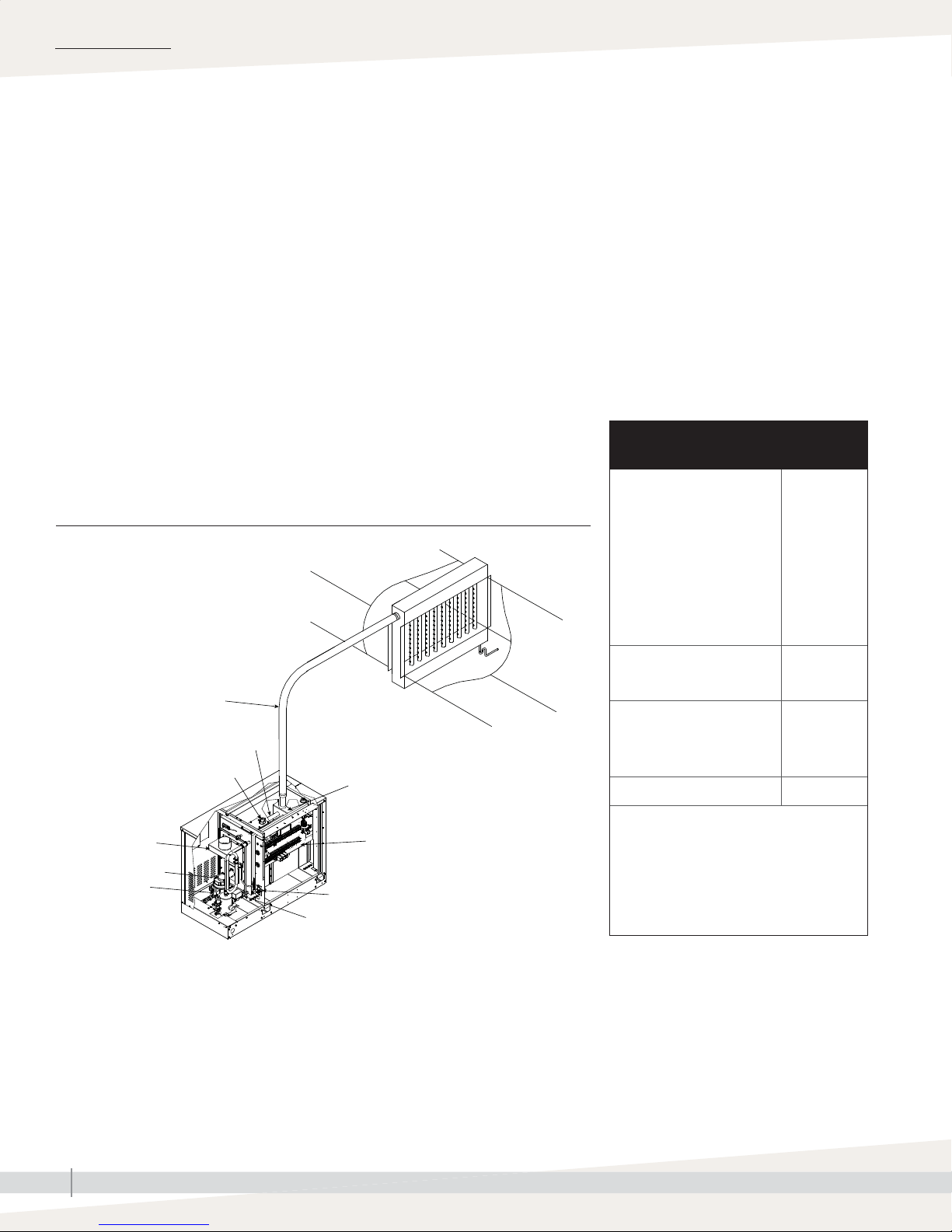
FIGURE 2-1: GTS HUMIDIFIER, TAP/SOFTENED WATER
Duct dispersion option shown: Ultra-sorb Model LV
Supply water guidelines
Supply water quality is an important component
of humidifi er reliability and maintenance.
Examples:
• Corrosive water can decrease the service life
of the humidifi er.
• Excessive water hardness can increase the
humidifi er maintenance requirements.
To maximize humidifi er service life and
minimize humidifi er maintenance, DriSteem
has established guidelines for supply water See
Table 2-1.
Table 2-1:
DriSteem supply water guidelines
Chlorides*
RO or DI water
Softened water
Tap water
* Damage caused by
chloride corrosion is
not covered by your
DriSteem warranty.
< 5 ppm
< 25 ppm
< 50 ppm
Steam hose or tubing
Water level probe
Blower
Gas valve
Steam outlet
Heat exchanger
Control componentsFlue box
Supply water connection
Drain valve
Total hardness
Tap water < 500 ppm
pH
RO, DI, or softened water
Tap water
Silica < 15 ppm
You may wish to take action to mitigate
potential negative effects to your
humidifi er. Supply water outside of these
guidelines may void your DriSteem
warranty. Please contact your DriSteem
Representative or DriSteem Technical
Support if you need advice.
OM-1247_ab mc_071912_1545
7 to 8
6.5 to 8.5
GTS INSTALLATION, OPERATION, AND MAINTENANCE MANUAL
2
Page 9
Product overview
PRODUCT OVERVIEW
RO/DI WATER OPTION
GTS humidifi ers with the RO/DI water option control water level using a
fl oat valve (see Figure 3-3). These humidifi ers produce chemical-free steam
and provide accurate, reliable humidifi cation control. These humidifi ers are
virtually maintenance-free and require very little or no downtime.
Note: GTS humidifi ers with the RO/DI water option can be converted in the
fi eld for use with tap/softened water.
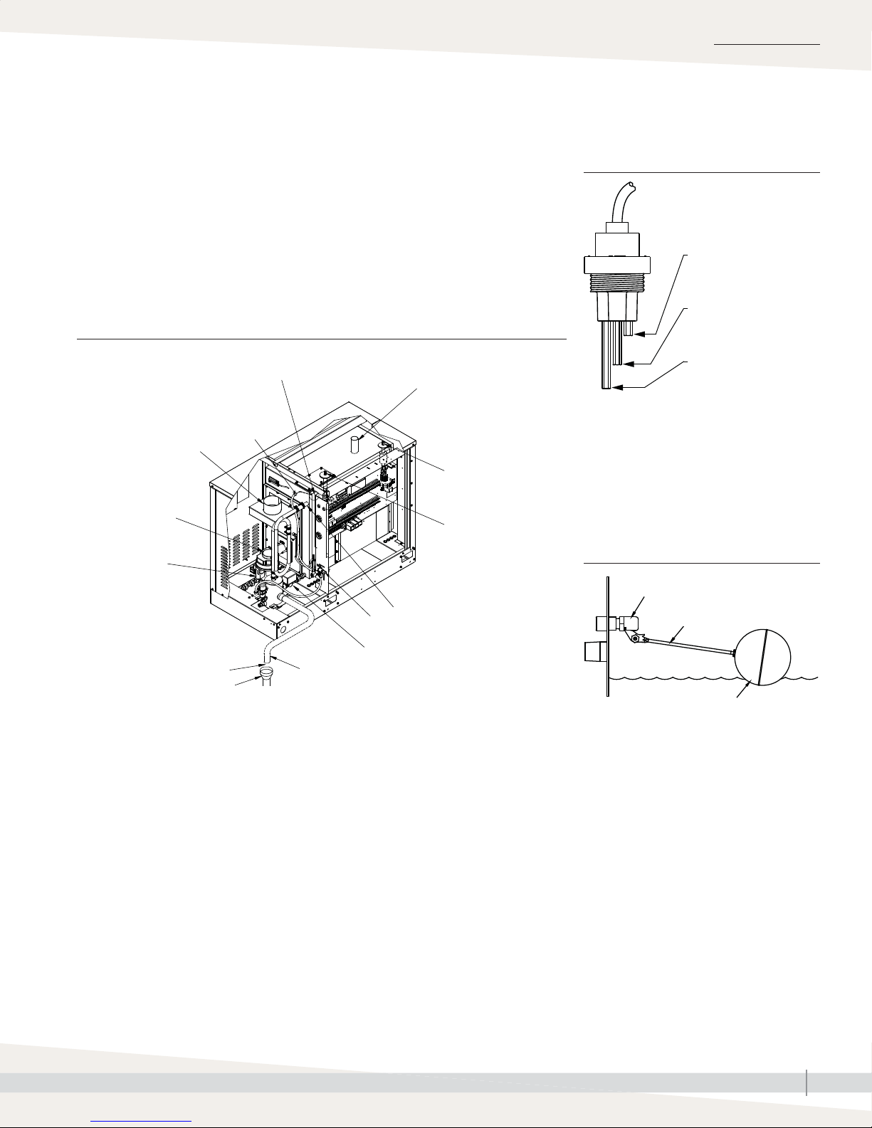
FIGURE 3-2: GTS HUMIDIFIER, RO/DI WATER OPTION
Float for water fi ll valve
Supply water line
Flue connection
Blower
Gas valve
Steam outlet
Redundant low
water cutoff
sensor
Float-operated
low water
cutoff
FIGURE 3-1: WATER LEVEL CONTROL
FOR TAP/SOFTENED WATER
VLC-OM-030
Fill valve closes when
water level rises to this
probe.
Fill valve opens when
water level is below this
probe.
Low-water cutoff. The
controller disables the
burner if the water level
drops below this probe.
Humidifi ers using tap or softened water control
water levels electronically using a three-rod
probe. The controller responds with the above
actions when the water level reaches each rod.
FIGURE 3-3: WATER LEVEL CONTROL
FOR RO/DI-WATER OPTION
OM-1248
Air gap
Open drain
Note: Dashed lines indicate supplied by installer
Drain piping
Overfl ow outlet
Supply water connection
Drain valve
Fill valve
Float rod
VLC-OM-026
Humidifi ers with the RO/DI water option control
water level using a fl oat valve. A low-water
cutoff switch is used as a low-water safety.
Float ball
GTS INSTALLATION, OPERATION, AND MAINTENANCE MANUAL
3
Page 10
SPECIFICATIONS
Models, capacities, electrical specifi cations, and weights
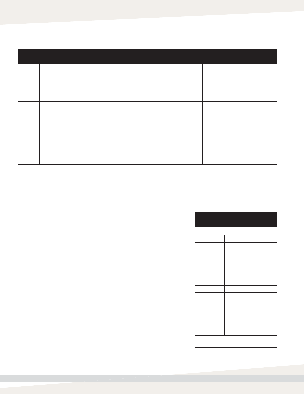
Table 4-1:
GTS models, capacities, electrical specifications, and weights, North American models
Maximum
GTS
model
GTS-100 75 34 100 29 2.76 9 34.1 48 181.7 700 320 375 170 800 365 500 230 1.8 2.8
GTS-200 150 68 200 59 5.52 18 68.1 48 181.7 700 320 375 170 800 365 500 230 1.8 2.8
GTS-300 225 102 300 88 8.28 27 102.2 52 196.8 850 385 450 205 1000 455 600 270 3.0 4.0
GTS-400 300 136 400 117 11.04 36 136.3 52 196.8 850 385 450 205 1000 455 600 270 3.0 4.0
GTS-500 375 170 500 147 13.80 45 170.3 76 287.7 1100 500 600 270 1450 660 950 430 4.5 5.5
GTS-600 450 204 600 176 16.56 54 204.4 76 287.7 1100 500 600 270 1450 660 950 430 4.5 5.5
GTS-700 525 238 700 205 19.32 63 238.5 89 336.9 1400 635 700 320 1750 795 1050 475 6.0 7.0
GTS-800 600 272 800 234 22.08 72 272.5 89 336.9 1400 635 700 320 1750 795 1050 475 6.0 7.0
* Add 15 full load amps for Outdoor Enclosure heater load on all GTS models, add 1 full load amp for an Outdoor Enclosure without heaters.
** Add 10% to account for skim and automatic drain/fl ush features if utilized (tap/softened water units only).
CAPACITY NOTES
steam
capacity
lbs/hr kg/h MBh kW m
Input
Water usage
at maximum
gals/hrlitres/
3
/h
capacity**
hr
Tank
volume
gals litres lbs kg lbs kg lbs kg lbs kg
Operating
• At sea level, approximately 152 Btu are required to raise the temperature
of one pound of water from 60 °F to 212 °F. (At sea level, approximately
GTS GTS with Outdoor Enclosure
weight
Shipping
weight
Operating
weight
Important: See Pages 70 and 71 for
additional European model specifi cations and
capacity notes.
Shipping
weight
Full load
amps*
120V
60 Hz
352 kJ are required to raise the temperature of one kilogram of water from
16 °C to 100 °C.)
• An additional 970 Btu are required to change the state of one pound of
212 °F water to vapor. (An additional 2257 kJ are required to change the
state of one kilogram of 100 °C water to vapor.)
• Another factor to consider is condensation steam loss from piping. See
Table 32-2.
For more detailed information about condensation steam loss, see the DriSteem
Design Guide, or see DriCalc, DriSteem’s free sizing and selection software,
available at www. dristeem.com.
LP GAS
All models operate at rated input
HIGH ALTITUDE
An input derate exists when operating units at a high altitude. See Table 4-2
for high altitude derate information.
Table 4-2:
High altitude derate
Altitude
feet meters
0–2000 0–610 0
2001–2500 610–765 2*
2501–3000 765–915 4*
3001–3500 915–1065 6*
3501–4000 1065–1220 8*
4001–4500 1220–1370 10
4501–5000 1370–1525 12
5001–5500 1525–1675 14
5501–6000 1675–1830 16
6001–6500 1830–1980 18
6501–7000 1980–2135 20
7001–7500 2135–2285 22
7501–8000 2285–2440 24
* GTS-400 models are derated 10% from
2001 through 4500 ft in Canada.
Input
derate %
230V
50 Hz
GTS INSTALLATION, OPERATION, AND MAINTENANCE MANUAL
4
Page 11
Dimensions
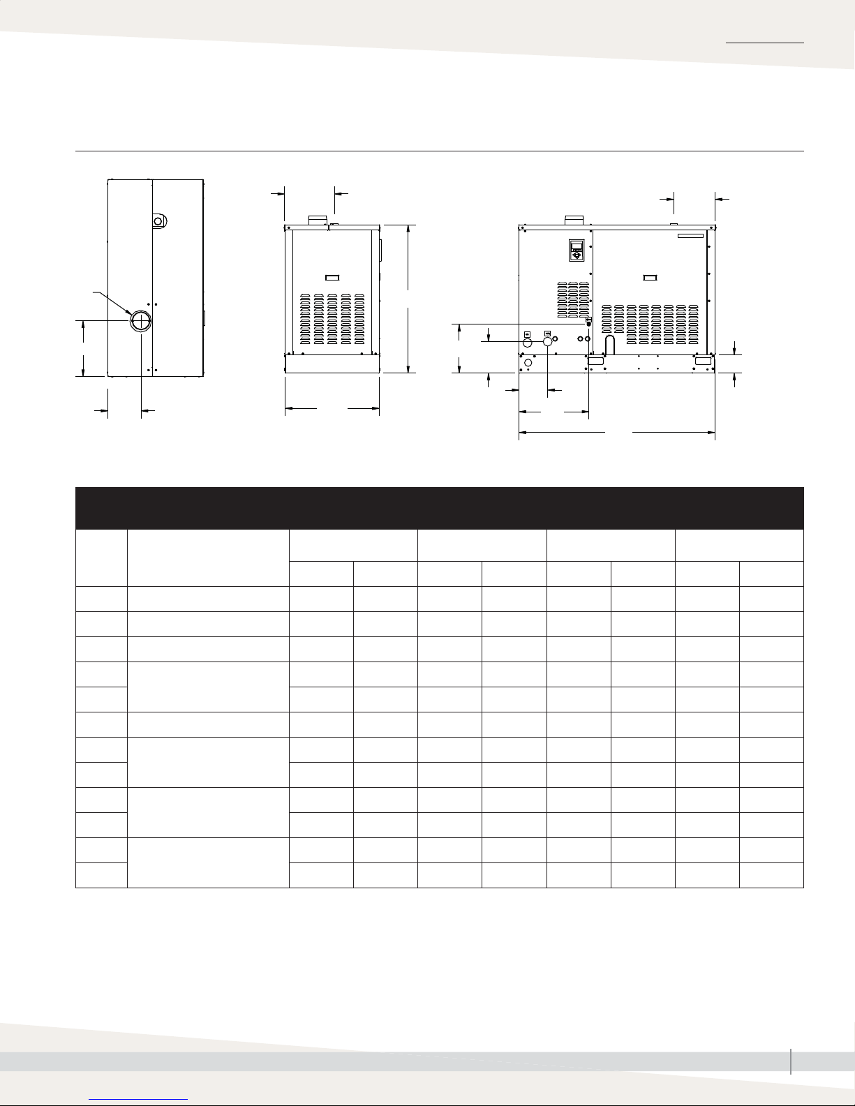
FIGURE 5-1: DIMENSIONS
SPECIFICATIONS
Side viewFront viewTop view
F
D
E
Table 5-1:
Dimensions
OM-1203
Description
G
C
J
L
M
B
GTS-100
GTS-200
inches mm inches mm inches mm inches mm
GTS-300
GTS-400
K
A
GTS-500
GTS-600
H
5" (127 mm)
GTS-700
GTS-800
A Overall length 54.35 1380 54.35 1380 54.35 1380 54.35 1380
B Overall width 26.38 670 32.38 822 42.38 1076 48.38 1229
C Shroud height 41.00 1040 41.00 1040 41.00 1040 41.00 1040
D
Flue position
E 9.13 232 13.13 334 16.63 422 19.13 486
F Flue diameter 5.00 127 7.00 178 8.00 203 10.00 254
G
Steam outlet position
H 11.63 295 11.63 295 11.63 295 11.63 295
J
Fill valve connection position
K 19.38 492 19.38 492 19.38 492 19.38 492
L
Drain position
M 8.00 203 8.00 203 8.00 203 8.00 203
15.50 394 14.75 375 14.95 375 14.00 356
13.88 353 20.38 518 29.13 740 35.00 889
13.50 343 13.50 343 13.50 343 13.50 343
8.25 210 8.25 210 8.25 210 8.25 210
GTS INSTALLATION, OPERATION, AND MAINTENANCE MANUAL
5
Page 12
INSTALLATION
Location and clearance recommendations
FINDING A LOCATION
• Provide a level, solid foundation for the humidifi er.
WARNING
• Locate the humidifi er as near as possible to a chimney or outside wall so
that the fl ue pipe from the humidifi er is short and direct.
• Locate the unit so it and its electrical components are protected from water
during humidifi er operation and service.
• Install the humidifi er in a location away (and protected) from drafts. If
installed in a separate room, follow the instructions concerning combustion
and ventilation air.
• Locate the humidifi er in an area where leakage from the tank or its
connections will not result in damage to the adjacent structure or to lower
fl oors of the structure. When such locations cannot be avoided, install a
suitable drain pan (adequately drained) under the humidifi er. The pan must
not restrict combustion airfl ow.
• If located in an insulated space, keep the humidifi er free and clear of
insulating materials. Insulating material can be combustible. Inspect the
humidifi er area when the humidifi er is installed or when insulation is added.
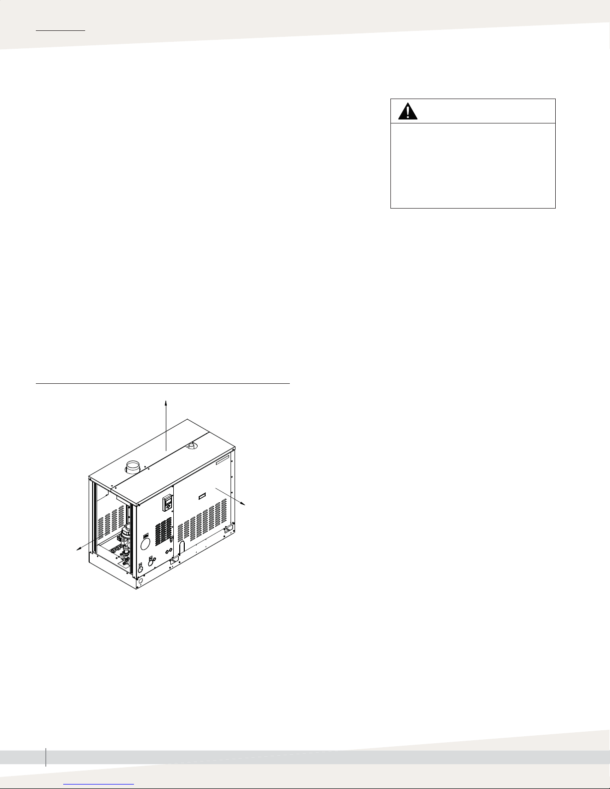
FIGURE 6-1: GTS CLEARANCE RECOMMENDATIONS
18" (457 mm)
Installation requirements
The humidifi er must be installed by
a qualifi ed technician and meet the
requirements of all governing codes.
Failure to follow these instructions could
cause severe bodily injury or death.
OM-1222
36" (914 mm)
30" (762 mm)
Note: DriSteem recommends a minimum of 1" (25 mm) clearance
between hot surfaces and combustible walls.
GTS INSTALLATION, OPERATION, AND MAINTENANCE MANUAL
6
Page 13
INSTALLATION
Outdoor Enclosure:
OUTDOOR ENCLOSURE MOUNTING OPTION
Mounting
The Outdoor Enclosure option is used when the GTS is installed outdoors.
The following information is not intended to supersede any requirements of
federal, state, or governing codes having jurisdiction; prior to locating the unit,
authorities having jurisdiction should be consulted.
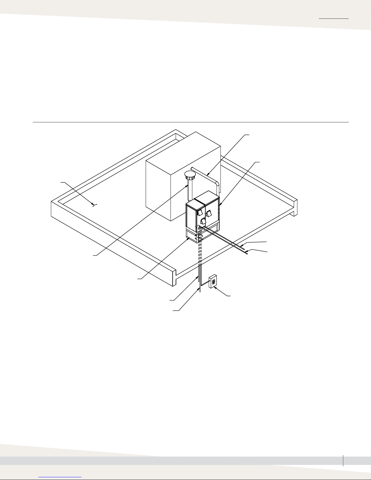
FIGURE 7-1: OUTDOOR ENCLOSURE TYPICAL INSTALLATION OVERVIEW
Roof surface
Steam piping
GTS humidifi er in Outdoor Enclosure
OM-1238
Electrical connections
Flue*
Curb
Drain piping
Water piping
* DriSteem recommends installing a drip tee directly after the factory supplied vent connection. Vertical section of fl ue must be at least 5' or meet all
governing codes, whichever is greater. DriSteem recommends installing a high wind vent cap on all GTS humidifi ers.
Vapor-logic keypad shown with optional cable length.
Keypad ships standard with 5' (1.5 m) of cable
Gas piping
GTS INSTALLATION, OPERATION, AND MAINTENANCE MANUAL
7
Page 14

INSTALLATION
Outdoor Enclosure: Mounting
LIFTING
The GTS Outdoor Enclosure must be lifted from the bottom base in a fashion
that holds it level and keeps it from tipping, falling, or twisting. If the unit
is severely twisted during handling, permanent damage can occur. It is the
installer’s responsibility to verify the handling equipment’s capability to safely
handle the unit.
Lift the Outdoor Enclosure by using special lifting lug hooks installed on the
unit. All lifting operations must be accomplished with a load spreader of
suffi cient width to ensure that the lifting cables clear the side of the unit.
GTS INSTALLATION, OPERATION, AND MAINTENANCE MANUAL
8
Page 15

Outdoor Enclosure: Mounting
LOCATION
• The GTS Outdoor Enclosure must be level and located so there is enough
clearance for opening the access panels.
• Verify that the position of pad or curb properly supports the unit and that
support structure dimensions coincide with unit dimensions.
• Do not locate unit in areas where the surrounding air has high levels of
particulates, such as some industrial parks or areas near highways.
• Locate unit so air intakes are not too close to exhaust fan outlets, gasoline
storage, or other contaminants that potentially could cause dangerous
situations. Using and storing gasoline or other fl ammable vapors and
liquids in open containers in the vicinity of this appliance is hazardous.
• When located on the roof, the air intakes must be a minimum of 14"
(360 mm) off the roof to prevent intake of snow or splashed rain. The unit
should be located so prevailing winds do not blow into the air intakes.
• An emergency drain is provided. In case of any water leak, water drains
onto the roof through this emergency drain.
INSTALLATION
• A keypad with standard 5' (1.5 m) cable ships mounted to the subpanel in
the GTS Outdoor Enclosure. The keypad must not come in contact with the
strip heaters or block the intake ventilation hood.
• If constant monitoring of the unit is desired, or if the unit is located in a
severe climate, install a remote mount keypad. Additional cable lengths up
to 500' (152 m) are available as an option for this mounting confi guration.
• Curbs (optional) are shipped knocked down for ease of transporting
to the roof. Curbs are manufactured of 14-gauge galvanized steel and
shipped with all hardware for bolt-together assembly. All holes are matched
before leaving the factory. Curb is to be a minimum of 14" (360 mm)
high. A closed-cell curb gasket with adhesive on one side is supplied with
hardware. An installation drawing also is included. To prevent moisture
from leaking into the building from either driving rain or melting snow,
install the gasket between the top of the curb and the base surface of the
unit.
GTS INSTALLATION, OPERATION, AND MAINTENANCE MANUAL
9
Page 16

INSTALLATION
Outdoor Enclosure: Mounting
BEFORE YOU BEGIN
• Prior to installing the unit, remove all packaging.
• During the transit, unloading, and setting of the unit, bolts and nuts may
become loose. Check that all nuts are tightened as required.
• There are three knockouts located on the right and left side of the enclosure.
DriSteem recommends running electrical power into the enclosure at these
knockouts.
• When pad-mounted or when the pipe chase cannot be used, the supply
water and drain piping can be run through the knockouts, although
preferably on the opposite side from the gas and electric.
• When unit is mounted on an outdoor curb, there must be a gasket between
the top of the curb and the base surface of the unit to prevent moisture from
leaking into the building from either driving rain or melting snow.
• The Outdoor Enclosure has two available steam distribution confi gurations.
The standard confi guration has a steam outlet at the back of the Outdoor
Enclosure for connecting to steam dispersion unit piping. The optional
internal steam distribution confi guration routes steam within the Outdoor
Enclosure and down through the pipe chase into a building. See Figures
11-1 and 12-1.
Important: A pipe chase is located inside the burner section of the
enclosure. DriSteem recommends using this pipe chase for both the supply
water piping and drain piping. Use insulation to completely fi ll the area
around the pipes to maintain proper enclosure pressure and protect unit
components from elevated moisture levels within building; insulation must
serve as an effective vapor barrier. Use the provided pipe chase cover to
seal off the pipe chase. Cut necessary holes and seal after installation.
• The heater package has two thermostat-controlled heaters: one strip heater
is located in the control section, and one strip heater is located in the
burner section to keep the enclosure at a constant minimum temperature.
Once the humidifi er tank is full and up to temperature, the tank will keep the
enclosure at an appropriate temperature. The heaters will turn off.
• See “Wiring” on Page 15 and “Piping” beginning on Page 16 for
directions on installing electrical, gas, fl ue, drain, and water connections. A
separate electrical service connection for the outdoor GTS is recommended.
Insulation and/or heat taping of water piping is recommended.
GTS INSTALLATION, OPERATION, AND MAINTENANCE MANUAL
10
Page 17
Outdoor Enclosure: Mounting
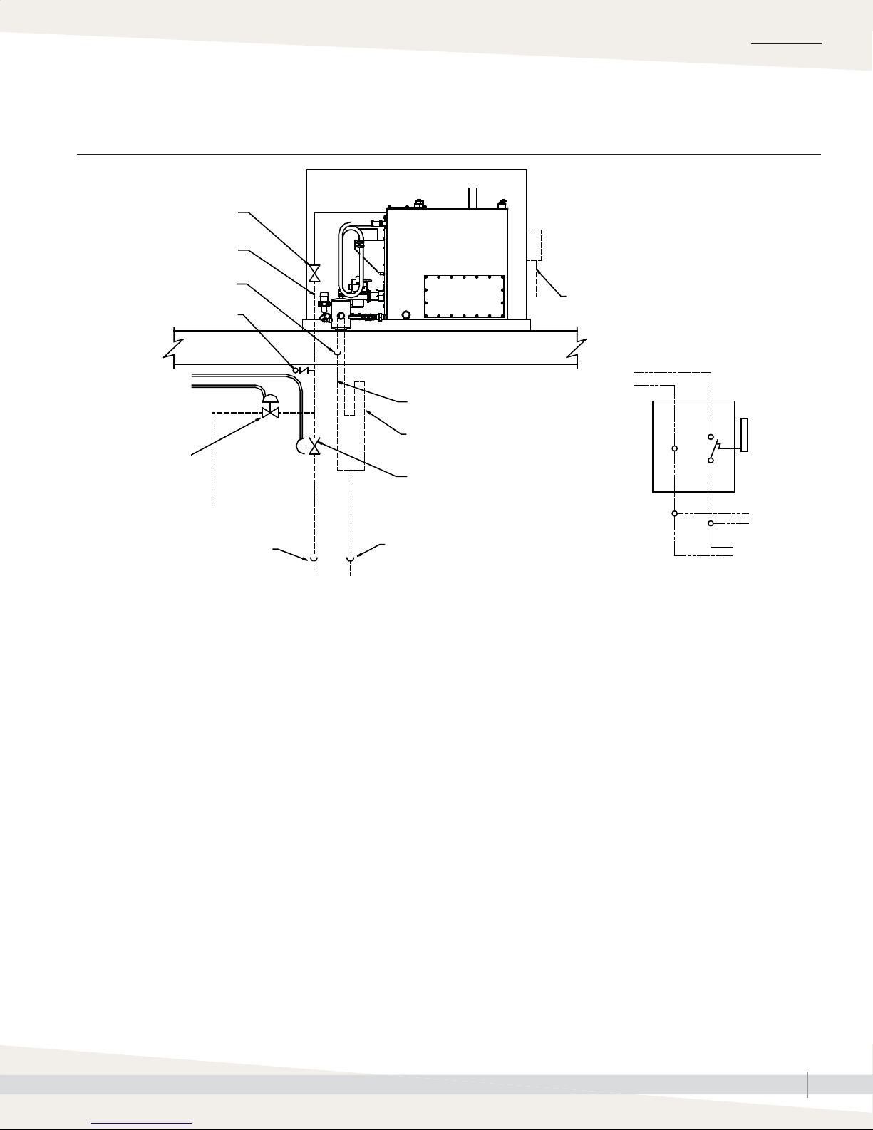
FIGURE 11-1: OUTDOOR ENCLOSURE INSTALLATION DETAIL
Normally closed fi ll valve
(by factory)
Supply water piping (by
installer) (See Note 2)
Open to drain
Vacuum breaker (by installer)
120 V (230 V in
Europe) from unit
disconnect or other
source (See Note 1)
Normally closed (fail
closed) min 3/8"
electric valve
(by installer)
Domestic water, 80 psig
(582 kPa) maximum
Open drain (See Note 4)
GTS humidifi er in
Outdoor Enclosure
installed on rooftop
Drain line, min. 1½" (See Note 3)
Optional water seal (P-trap) drain
line, min. 1½" (DN40) (See Note 3)
Normally open (fail open) min 1/2"
electric valve (by installer)
Open drain
(See Note 4)
Roof decking
OM-4045
Disconnect (by installer); see Detail A
120 V supply (230 V in
Europe)
120 V
(230 V in
Europe)
Disconnect
Heated building interior
INSTALLATION
Detail A
N
box
To valves
(by installer)
(See Note 1)
To GTS
humidifi er
Piping notes:
1. Insulate supply water piping to avoid dripping from condensation. To ensure that water does not remain in the fi ll line and freeze if there is a loss
of power, DriSteem recommends fi eld installing additional valves upstream of the fi ll valve in a conditioned space. Power these valves on the same
circuit as the GTS; if the power goes off, water drains out of the fi ll line to prevent freezing (see above). Supply power for these valves from the
same circuit that supplies the GTS.
2. Ensure that water lines are protected from freezing conditions.
• Install heat tracing and insulation on fi ll piping inside the Outdoor Enclosure.
• In extreme or critical applications in which the unlikely event of a water leak could cause severe damage, DriSteem recommends a thermostat
with a remote sensor on the fi ll line to cut power to the GTS and safety valves to stop fi ll water to the GTS and drain the fi ll piping when the
temperature is below freezing.
3. DriSteem recommends copper or iron drain piping for Outdoor Enclosures. On a loss of power the tank water will drain, but not be cooled by
the Drane-kooler because of the fi eld supplied safety shut-off valves. If it is critical to keep the Drane-kooler functional in the case of a power loss,
disconnect the Drane-kooler and relocate it down inside the conditioned space of the building. Pipe the supply water for the Drane-kooler before the
safety shut-off valves.
4. If copper or iron piping is used for both the fi ll and drain piping, these drains may be tied together. Locate 1" air gap only in spaces with adequate
temperature and air movement to absorb fl ash steam; otherwise, condensation may form on nearby surfaces. Refer to governing codes for drain
pipe size and maximum discharge water temperature.
GTS INSTALLATION, OPERATION, AND MAINTENANCE MANUAL
11
Page 18
INSTALLATION
Outdoor Enclosure: Mounting
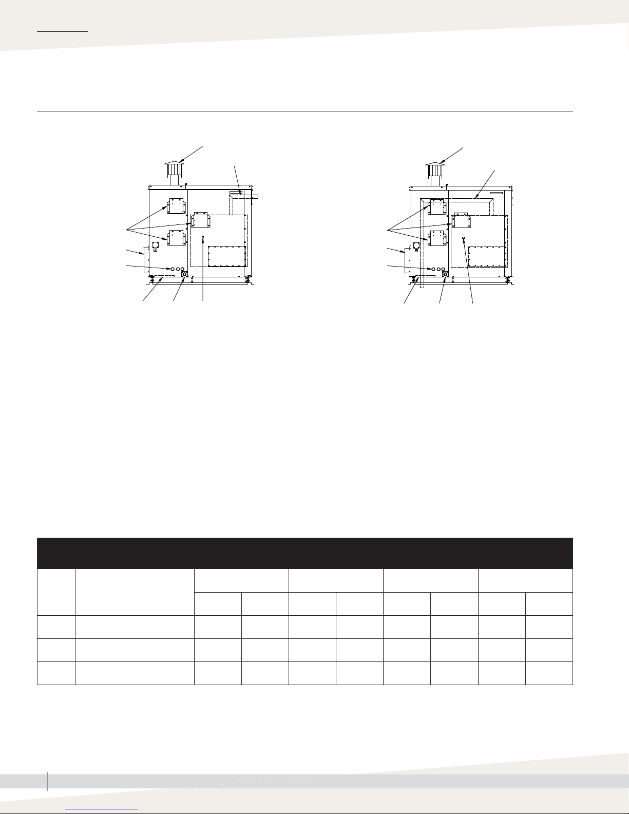
FIGURE 12-1: GTS OUTDOOR ENCLOSURE WITH STANDARD OR OPTIONAL STEAM OUTLET, ELEVATION VIEW
Standard steam outlet Optional steam outlet
OM-1228M
Ventilation fans
Combustion air intake
1½" (38 mm) knockouts
4" (102 mm) o.c.
Pipe chase
Emergency
drain
Flue piping (by installer)
Steam outlet (See Note 1)
GTS
humidifi er
Power block
OM-1227M
Ventilation fans
Combustion air intake
1½" (38 mm) knockouts
4" (102 mm) o.c.
Pipe chase
Emergency
drain
Flue piping (by others)
Steam outlet
(See Note 1)
GTS
humidifi er
Power block
Notes:
1. The Outdoor Enclosure has two available steam distribution confi gurations. The standard confi guration has a steam outlet at the back of the
Outdoor Enclosure for connecting to steam dispersion unit piping. The optional internal steam distribution confi guration routes steam within the
Outdoor Enclosure and down through the enclosure pipe chase into a building.
2. There are three knockouts located on the right and left side of the enclosure. Run the electrical power and gas piping into the enclosure at these
knockouts.
3. Piping from the GTS unit to the steam outlet is stainless steel pipe. Piping from the steam outlet to the dispersion assembly is provided by the
installer. Choose interconnecting steam piping material that is appropriate for the application (e.g., for high-purity steam applications, consider
using stainless steel interconnecting steam tubing). See Table 18-1 for steam outlet sizes.
4. The GTS housed in an Outdoor Enclosure will operate properly in operating temperature of –40 °F to 122 °F (–40 °C to 50 °C).
5. Install external fl ue piping shall be provided by installers and fi eld installed. The fl ue of the Outdoor Enclosure exits out the left side of the unit and
a vertical stack must be constructed. The stack must be a minimum of 5–10 feet (1.5–3.0 m) above the top of the roof. However, the exact height
varies depending on unit size, climate, etc. Governing codes prevail. A UL or UL/CSA (or equivalent) listed cap must be used and a drip tee
included. DriSteem recommends installing a high-wind vent cap on all GTS humidifi ers.
Table 12-1:
Outdoor Enclosure dimensions
Description
inches mm inches mm inches mm inches mm
A Enclosure height 54.63 1388 54.63 1388 54.63 1388 54.63 1388
B Enclosure width 26.00 660 32.00 813 42.00 1067 48.00 1219
C Enclosure length 57.25 1454 57.25 1454 57.25 1454 57.25 1454
GTS INSTALLATION, OPERATION, AND MAINTENANCE MANUAL
12
GTS-100
GTS-200
GTS-300
GTS-400
GTS-500
GTS-600
GTS-700
GTS-800
Page 19
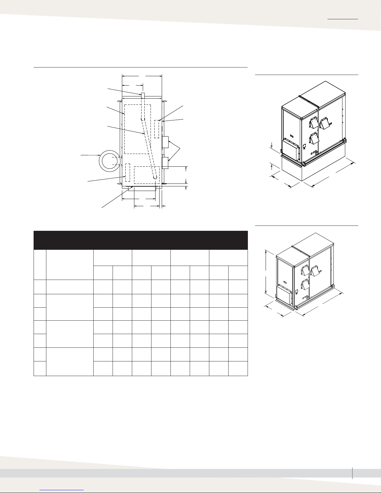
INSTALLATION
Outdoor Enclosure: Mounting
FIGURE 13-1: OUTDOOR ENCLOSURE TOP VIEW FIGURE 13-2: OUTDOOR ENCLOSURE
MOUNTED ON A CURB
Exit for standard steam outlet
T
Y
OM-7432
GTS humidifi er
Exit for optional steam outlet
(through pipe chase)
Flue (by installer)
Burner section heater
Access panel door
Table 13-1:
Outdoor Enclosure top view dimensions
GTS-100
Description
GTS-200
inches mm inches mm inches mm inches mm
Z
W
GTS-300
GTS-400
Control panel heater
Access panel door
Intake ventilation fans
X
V
U
GTS-500
GTS-600
OM-7431
14"
(356 mm)
C
B
FIGURE 13-3: OUTDOOR ENCLOSURE
MOUNTED FLUSH
OM-7430
GTS-700
GTS-800
A
T Enclosure width 26.00 660 32.00 813 42.00 1067 48.00 1219
U
Pipe chase position
V 3.00 76 3.00 76 3.00 76 3.00 76
W
Pipe chase size
X 11.00 279 11.00 279 11.00 279 11.00 279
Y
Steam pipe position
Z 21.00 533 27.00 686 37.00 940 43.00 109
3.00 76 3.00 76 3.00 76 3.00 76
16.00 406 16.00 406 16.00 406 16.00 406
14.12 359 20.12 511 30.12 765 36.12 917
B
C
GTS INSTALLATION, OPERATION, AND MAINTENANCE MANUAL
13
Page 20

INSTALLATION
Outdoor Enclosure: Operation
SEQUENCE OF OPERATION
• Power is applied to the Outdoor Enclosure.
• If the ambient temperature in the enclosure is below
50 °F (10 °C), the strip heaters are powered up. The strip heaters remain
on until the enclosure reaches 50 °F (10 °C) to ensure that the temperature
inside the enclosure does not drop below the freezing point.
• When there is no call for humidity, an aquastat maintains tank temperature
at the factory default of 70 °F (21 °C). This temperature can be reset in the
fi eld to be from 40-180 °F (4-82 °C).
• When the ambient temperature in the enclosure reaches 85 °F (29 °C), two
ventilation fans turn on to cool the electronic components. A high limit is
also provided to power down the GTS if the enclosure temperature reaches
150 °F (66 °C). In a high limit situation, the ventilation fans continue to run
and once the enclosure temperature falls below 130 °F (54 °C), the GTS
automatically resumes normal operation.
• A normally open drain valve is provided on the GTS Outdoor Enclosure to
drain the tank in the event of a power loss.
GTS INSTALLATION, OPERATION, AND MAINTENANCE MANUAL
14
Page 21
Wiring
INSTALLATION
WARNING
Grounding
Installation must meet the requirements of governing codes or, in the absence of
governing codes, in accordance with the National Electrical Code, ANSI/NFPA
70, or Canadian Electrical Code, CSA C22.1, or IEE wiring regulations (BS7671).
The electrical subpanel must have an uninterrupted or unbroken ground to minimize
personal injury if an electrical fault should occur. This ground can consist of electrical
wire or conduit approved for electrical ground when installed in accordance with
existing electrical codes. Do not use gas piping as an electrical ground.
• GTS humidifi ers must be supplied with 120 Vac, 60 Hz (North American
models) or 230 Vac, 50 Hz (European models) separately fused electrical
service. The GTS humidifi er is equipped with a transformer to step down the
voltage to 24 Vac control voltage.
• When installed, the GTS humidifi er must be electrically grounded in
accordance with governing codes or, in the absence of governing codes,
in accordance with the National Electrical Code, ANSI/NFPA 70; or
Canadian Electrical Code, CSA C22.1; or IEE wiring regulations (BS7671).
In North America, the electrical conductors shall be Type MTW (105 °C)
AWG #14 (2.5 mm2) wire for 120 V line voltage , with BLACK WIRE
for HOT, WHITE WIRE for NEUTRAL, GREEN AND YELLOW WIRE for
GROUND. Units with Outdoor Enclosure must use AWG #12 (4 mm2) for
120 V line voltage. Use #18 gauge (1 mm2) for control wiring.
WARNING
Fire hazard
Do not connect aluminum wire between
disconnect switch and humidifi er. Use
only copper wire. Failure to follow
these instructions could cause a fi re,
resulting in severe bodily injury, death,
or signifi cant property damage.
In Europe, the electrical conductors shall be Type MTW (105 °C) 2.5 mm2
wire for line voltage (230V), with BLACK WIRE for LINE, BLUE WIRE for
NEUTRAL, GREEN AND YELLOW WIRE for GROUND, and 2.5 mm2 wire
for control wiring.
• All electrical components and wiring must be protected from mechanical
damage and water. The control system requires an earth ground for proper
operation.
• The GTS humidifi er is adjusted for correct performance. Only a qualifi ed
gas appliance technician may alter throttle setting.
• Check the electric current characteristics and capacity requirements against
the nameplate. All wiring must be in accordance with all governing codes
and with the GTS wiring diagrams located inside the control cabinet. See
the electrical specifi cations in Table 4-1 (North America) and Table 71-1
(Europe).
• Refer to the Vapor-logic Installation and Operation Manual for additional
information on the controller furnished with this GTS humidifi er.
GTS INSTALLATION, OPERATION, AND MAINTENANCE MANUAL
15
Page 22
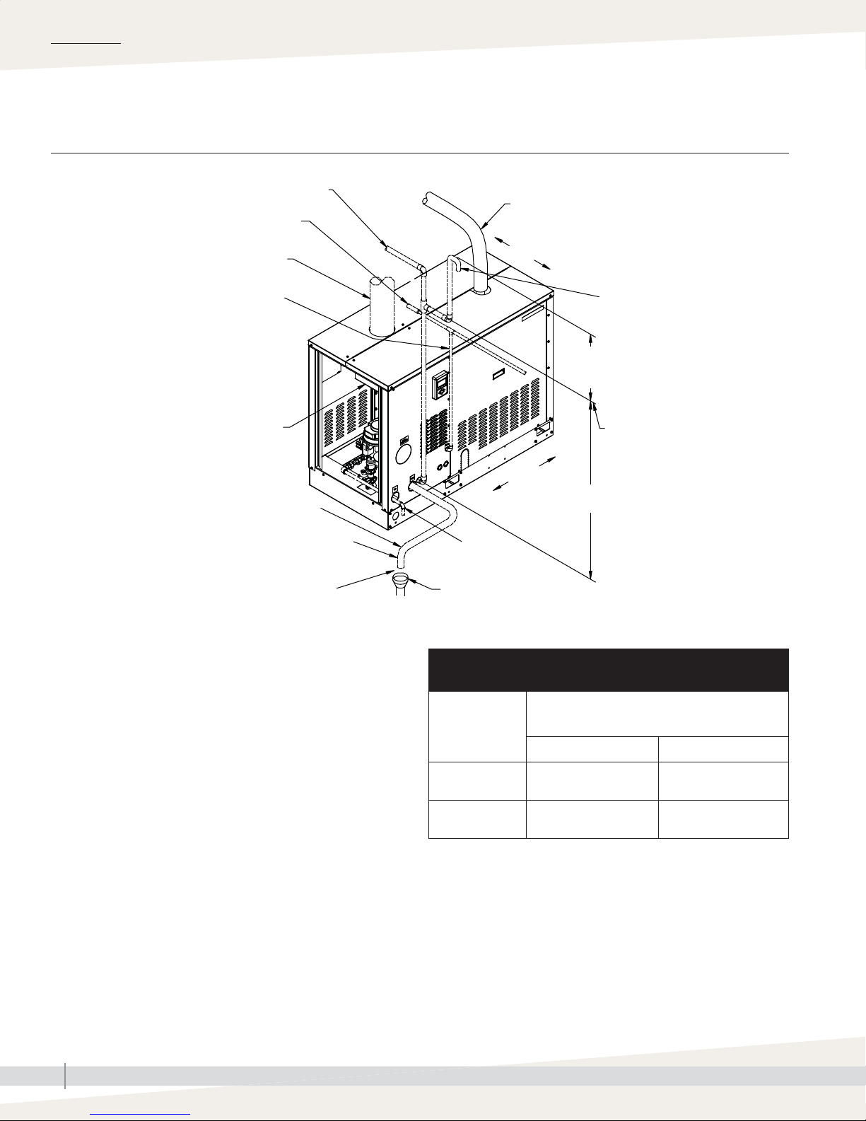
INSTALLATION
Piping: Tap/softened water
FIGURE 16-1: GTS FIELD PIPING OVERVIEW, TAP/SOFTENED WATER
Optional condensate return piping from dispersion
unit; 3/4" pipe thread (DN20) fi tting at humidifi er
Shock arrester recommended to reduce
water hammer, by installer
Flue size per governing codes. Do not reduce.
Steam hose or tubing
Install level
Supply water line; water pressure range
25 to 80 psi (172 to 582 kPa); water
conductivity minimum 100 μS/cm
Flue connection
Offset humidifi er from fl oor drain to prevent
fl ash steam from rising into the humidifi er
1½" NPT (DN40) drain piping must be
rated for 212 °F (100 °C) (by installer)
1" (25 mm) air gap
Notes:
• Locate air gap only in spaces with adequate temperature and air
movement to absorb fl ash steam; otherwise, condensation may form
on nearby surfaces. Refer to governing codes for drain pipe size and
maximum discharge water temperature.
• Dashed lines indicate provided by installer.
• Humidifi er fl ue gases must be vented to the outside atmosphere.
• Supply water inlet is more than 1" (25 mm) above skim/overfl ow port,
eliminating the possibility of backfl ow or siphoning from tank. No
additional backfl ow prevention is required; however, governing codes
prevail.
• Damage caused by chloride corrosion is not covered by your DriSteem
warranty.
• See the next page for recommended supply water piping for RO/DI
water models.
Air vent tube
6" (150 mm)
minimum vent height
Air vent height must be equal to
or greater than dimension H
(see Table 16-1)
Install level
H
Gas inlet
connection
Open drain
required. See fi rst
note below.
OM-1208b
Table 16-1:
Height (H) required to overcome GTS internal pressure (H)
GTS model
(tap/softened
water)
100, 200 35 889
300, 400, 500,
600, 700, 800
Dimension H in drawing above = height required to
overcome humidifi er internal pressure
inches mm
41 1041
GTS INSTALLATION, OPERATION, AND MAINTENANCE MANUAL
16
Page 23
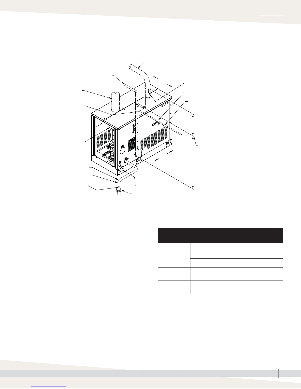
RO/DI water option Piping:
FIGURE 17-1: GTS FIELD PIPING OVERVIEW, RO/DI WATER OPTION
Steam hose or tubing
INSTALLATION
Optional condensate return piping from dispersion
unit; 3/4" pipe thread (DN20) fi tting at humidifi er
Flue size per governing codes.
Do not reduce.
Supply water line; water pressure
range 25 psi to 80 psi (172 kPa
to 582 kPa); fi rst 3' (1 m) of supply
line must be rated for 212 °F
(100 °C)
Flue connection
Offset humidifi er from fl oor
drain to prevent fl ash steam
from rising into the humidifi er
1½" (DN40) drain piping must
be rated for 212 °F (100 °C)
1" (25 mm) air gap
Install level
Install level
Gas inlet
connection
Open drain required.
See fi rst note below.
Air vent tube
If water piping to humidifi er is nonmetallic, we
recommend a 2" (50 mm) water seal in the supply
water line to isolate steam during RO/DI water system
maintenance.
Inlet strainer by installer
6" (150 mm)
minimum vent height
OM-1223
H
Air vent tube height must be equal to or
greater than dimension H (see Table 17-1)
Notes:
• Locate air gap only in spaces with adequate temperature and air
movement to absorb fl ash steam; otherwise, condensation may form
on nearby surfaces. Refer to governing codes for drain pipe size and
maximum discharge water temperature.
• Dashed lines indicate provided by installer.
• Humidifi er fl ue gases must be vented to the outside atmosphere.
• Supply water inlet is more than 1" (25 mm) above overfl ow port,
eliminating the possibility of backfl ow or siphoning from tank. No
additional backfl ow prevention is required; however, governing codes
prevail.
• Damage caused by chloride corrosion is not covered by your DriSteem
warranty.
• In order to minimize RO/DI water use, disconnect factory piping to the
water tempering device and pipe directly to tap water.
• See the previous page for recommended supply water piping for tap/
softened water models.
Table 17-1:
Height (H) required to overcome GTS internal pressure
GTS model
(RO/DI water
option)
100, 200 35 889
300, 400, 500,
600, 700, 800
Dimension H in drawing above = height required to
overcome humidifi er internal pressure
inches mm
41 1041
GTS INSTALLATION, OPERATION, AND MAINTENANCE MANUAL
17
Page 24

INSTALLATION
Supply water and drain overflow connections Piping:
Regardless of the type of water used, the following general instructions MUST
be followed:
• Make union connections at the humidifi er on the make-up water supply and
drain/overfl ow lines.
• Provide a shutoff valve in the supply water line to isolate the humidifi er from
the water system while servicing.
• Shock arrester, provided by installer, is recommended to reduce water
hammer.
• A 1" (25 mm) opening is provided in the humidifi er tank to accommodate
skim and/or overfl ow protection.
Note: Follow governing code requirements regarding size of drain pipe.
• Use insulating unions or bushings to make connections between copper and
other dissimilar metal fi ttings, such as galvanized steel. These insulating
fi ttings are required to minimize electrolytic corrosion, which results from the
direct connection of dissimilar metals in a water system.
• Before beginning ignition sequence of the humidifi er at a new installation,
make sure the humidifi er tank is full of water and the water is free to fl ow
into the tank.
• If planning to use heated supply water, disconnect the supply water line to
the water tempering device at the fi ll manifold and reconnect it to a cold
water supply. This will ensure that the water tempering device operates
properly.
Table 18-1:
Connection sizes
Description
Gas supply
Sealed combustion piping (optional) 4 100 4 100 4 100 4 100
Flue vent 5 125 7 180 8 200 10 250
Supply water to fi ll valve and tempering
device*
Drain
Steam outlet**
Condensate return (recommended)
Notes:
To minimize RO/DI water use, disconnect factory piping to the water tempering device and pipe directly to tap water.
*
For pipe thread steam outlet options, see DriCalc, DriSteem’s free sizing and selection software, available at www. dristeem.com.
**
• If planning to use heated supply water, disconnect the water line to the water tempering device at the fi ll manifold, and reconnect it to a cold
water supply. This will ensure that the water tempering device operates properly.
GTS-100 and GTS-200 GTS-300 and GTS-400 GTS-500 and GTS-600 GTS-700 and GTS-800
inches DN inches DN inches DN inches DN
1/2
(pipe thread)
3/8
(pipe thread)
1½
(pipe thread)
2
(hose)
3/4
(pipe thread)
15
10
40
50
20
1
(pipe thread)
3/8
(pipe thread)
1½
(pipe thread)
3
(fl ange)
3/4
(pipe thread)
25
10
40
80
20
1
(pipe thread)
3/8
(pipe thread)
1½
(pipe thread)
4
(fl ange)
3/4
(pipe thread)
25
10
40
100
20
1¼
(pipe thread)
3/8
(pipe thread)
1½
(pipe thread)
4
(fl ange)
3/4
(pipe thread)
32
10
40
100
20
GTS INSTALLATION, OPERATION, AND MAINTENANCE MANUAL
18
Page 25

Supply water Piping:
SUPPLY WATER PIPING GENERAL INSTRUCTIONS
The GTS humidifi er has a 1" (25 mm) internal air gap to prevent back
siphoning into a potable water system. However, some governing codes may
require additional protection such as a vacuum breaker or backfl ow preventer.
The supply water pressure range must be 25 psi to 80 psi (172 kPa to 552
kPa). When nonmetallic water piping is used, it must be rated to withstand
212 °F (100 °C) or greater temperature. If not, the fi nal three feet of piping
connected to the humidifi er should be metallic and should not be insulated.
TAP/SOFTENED SUPPLY WATER PIPING
The supply water assembly has a 3/8" pipe thread (DN10) connection. Since
the primary component of the supply water assembly is a solenoid valve, there
may be noise issues that surface during a fi ll cycle.
During a fi ll cycle, the supply water drops the water temperature in the tank
and may collapse the steam, which can cause a low rolling sound. To diminish
this, adjust the factory-supplied needle valve (installed prior to the fi ll valve) to
decrease the water fi ll rate, and/or use hot supply water.
INSTALLATION
In cases where water hammer occurs when the fi ll solenoid closes, a shock
arrester is recommended. Reducing the supply water pressure (minimum
25 psi [172 kPa]) or using fl exible tubing (rated for 212 °F [100 °C] minimum
continuous operating temperature) may diminish the noise, but installing a
shock arrester is the best solution.
The minimum water conductivity for the GTS tap/softened water model is 100
μS/cm.
GTS INSTALLATION, OPERATION, AND MAINTENANCE MANUAL
19
Page 26
INSTALLATION
Supply water Piping:
SUPPLY WATER PIPING, RO/DI WATER OPTION
GTS humidifi ers with the RO/DI water option control water level with a fl oat
valve, and have a 3/8" pipe thread (DN10) connection. For models with the
end-of-season drain option, a solenoid valve is installed prior to the fl oat valve.
The end-of-season feature shuts off the supply water and drains the tank when
there is no demand for humidity for 72 hours. (This length of time is a default
setting and is user-adjustable. See the Vapor-logic Installation and Operation
Manual for more information.)
When using nonmetallic tubing for supply water, it must be rated for 212 °F
(100 °C) minimum continuous operating temperature. DriSteem recommends
installing a 3' (1 m) piece of noninsulated stainless steel pipe directly off
the humidifi er prior to connecting to the nonmetallic tubing. When using
nonmetallic tubing, DriSteem recommends the installer place a 2" (50 mm)
water seal/loop in the supply water line to isolate steam during RO/DI water
system maintenance. See Figure 17-1.
DriSteem recommends installing a strainer in the supply water line to prevent
clogging of the solenoid valve or fl oat valve orifi ce. A strainer is highly
recommended when the humidifi er has the end-of-season drain option. The
strainer prevents particulate from collecting at the solenoid valve seat.
Important: Damage caused by chloride
corrosion is not covered by your DriSteem
warranty. See “Supply water guidelines” on
Page 2.
In order to minimize RO/DI water use, disconnect factory piping to the water
tempering device and pipe directly to tap water.
WARNING
Fire hazard
If a GTS humidifi er with the RO/DI water option is supplied with tap water, the fl oat
valve assembly will become clogged, and particulate will accumulate on the low
water cutoff switch (fl oat switch). This will cause failure of a critical safety circuit and
the potential for a dry tank fi re. A dry tank fi re can cause heat exchanger, steam hose,
and wire insulation failure, severe property damage, severe personal injury, or death.
GTS INSTALLATION, OPERATION, AND MAINTENANCE MANUAL
20
Page 27
INSTALLATION
Drain Piping:
The drain line piped from the humidifi er must be run to an approved sanitary
waste or suitable drain. Although the GTS humidifi er is equipped with
integral water tempering, if nonmetallic drain pipe or hose is used, DriSteem
recommends it be rated for 212 °F (100 °C) minimum continuous operating
temperature.
Minimum drain pipe size is 1½" (DN40) inside diameter. Do not reduce the
size of the drain piping. If the length of the drain piping exceeds 10' (3 m),
increase the pipe size. If combining multiple drain lines together, ensure proper
common pipe sizing practices are used.
Do not locate the humidifi er directly above a fl oor drain — skim and drain
water dumped into the drain will cause fl ash steam. This steam will rise
and saturate electrical components, adversely affecting component life and
performance.
An open drain with a 1" (25 mm) air gap between the drain piping and the
drain is required. Locate air gap only in spaces with adequate temperature
and air movement to absorb fl ash steam; otherwise, condensing on nearby
surfaces may occur.
Drain piping after the water seal must be pitched a minimum of 1/8"/ft (1%)
toward the drain. Governing codes may require more pitch.
If the proximity of a drain requires the humidifi er drain and skim water to
be lifted, use a water pump with capacity of at least 12 gallons per minute
(gpm) or 45.4 litres per minute (L/m). Contact DriSteem to order a drain pump
suitable for your installation. A check valve is required on the discharge of the
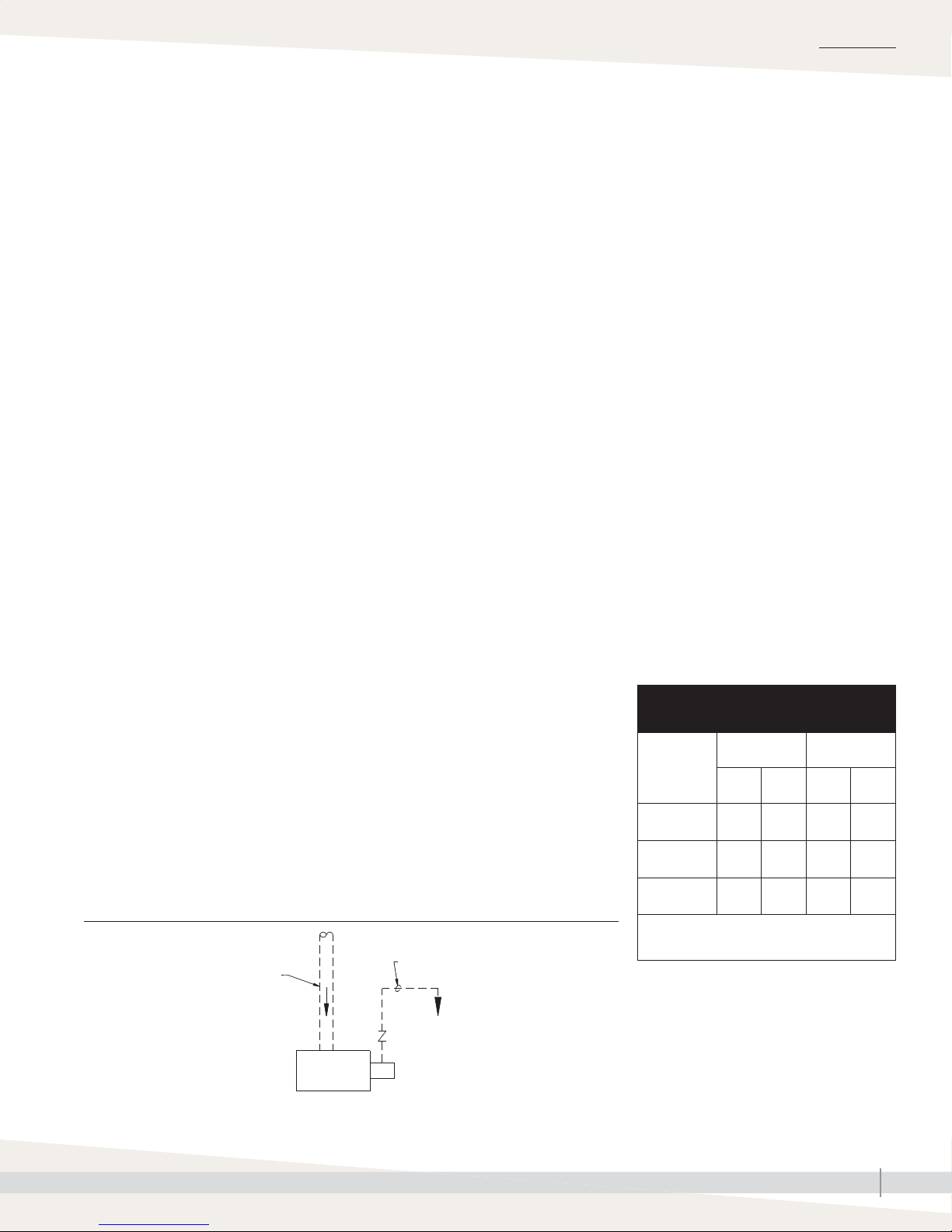
pump (see Figure 21-1). Electrical power for the pump is independent of the
humidifi er.
The GTS humidifi er has an auxiliary 1½" (DN40) drain outlet located below
the subpanel. This drain outlet can be hard-piped during installation to enable
rapid tank draining before maintenance. This outlet can also provide access for
removing scale from the tank bottom.
FIGURE 21-1: LIFTING DRAIN WATER
Discharge piping, by installer
Inlet drain water piping, by installer
Integral water tempering chamber
Governing codes may require that the 212 °F
(100 °C) drain and skim/overfl ow water
from the humidifi er be tempered before it is
discharged into the building drain piping. The
GTS humidifi er has an integral water tempering
chamber that tempers 6 gpm (22.7 L/m) of
212 °F (100 °C) water to 140 °F (60 °C). The
water tempering sequence of operation is:
1. Hot water discharged from the humidifi er
enters the water tempering chamber from
either the skim/overfl ow port or the tank
drain.
2. Cold water enters the water tempering
chamber through a temperature-actuated
valve to mix with the hot discharged water.
3. Tempered water at 140 °F (60 °C) maximum
exits through the water tempering chamber
side outlet for safe discharge into a
municipal sewer system or PVC pipe.
4. In order to minimize RO/DI water use,
disconnect factory piping to the water
tempering device and pipe directly to tap
water.
5. If planning to use heated supply water,
disconnect the water line to the water
tempering device at the fi ll manifold, and
reconnect it to a cold water supply. This
will ensure that the water tempering device
operates properly.
Table 21-1:
Integral water tempering specifications
Maximum
Water type
Hot water
infl ow
Cold water
infl ow*
Tempered
water outfl ow
* Cold water infl ow pressure must be between
25 psi and 80 psi (172 kPa and 552 kPa).
low rate
U.S.
L/m °F °C
gpm
6 22.7 212 100
6 22.7 70 21
12 45.4 140 60
Maximum
temperature
Water pump
DC-1117
Note: Size water pump to handle a minimum of 12 gpm (45.4 L/m).
Check valve
GTS INSTALLATION, OPERATION, AND MAINTENANCE MANUAL
21
Page 28
INSTALLATION
Piping:
GAS PIPING GUIDELINES
Gas
• After threading and reaming the ends of the pipes, inspect piping and
remove loose dirt and chips.
• Support piping so there are no strains imposed on unit or controls.
• Use two wrenches when connecting piping to unit or controls.
• Provide a drip pocket before each unit and in the line where low spots
cannot be avoided.
• Takeoff to unit should come from top or side of main to avoid trapping
condensate.
• Piping that is subject to wide temperature variations should be insulated.
• Pitch piping up toward unit at least 1/4" (6 mm) per 15' (4.5 m) of
horizontal run.
• Compounds used on threaded joints of gas piping must be resistant to the
harmful action of liquefi ed petroleum gases.
WARNING
Fire or explosion hazard
Purge air before lighting unit by disconnecting piping at gas control. In no case should
line be purged into heat exchanger. Failure to follow these instructions could cause a
fi re or explosion, resulting in bodily injury, death, or signifi cant property damage.
WARNING
Fire hazard
Supply the humidifi er only with the
gas type (natural gas or LP gas) listed
on the humidifi er name plate. Failure
to supply the humidifi er with the listed
gas type could result in burner failure
or a fi re, causing property damage,
personal injury, or death.
To convert the humidifi er to natural
gas or LP gas, contact DriSteem
Technical Support or your DriSteem
Representative/Distributor.
Important: For North American models,
the recommended supply pressure is 7" wc
(1.75 kPa) for natural gas or 11" wc (1.83
kPa) for LP gas.
For European models, the required supply
pressure is 20 or 25 mbar for natural gas and
30, 37, or 50 mbar for propane gas.
• After installation, check fi eld piping and humidifi er gas train for gas leaks.
• Do not use soap solution or open fl ame on humidifi er gas train. A gas leak
detector is recommended.
• Install a ground joint union and a manual shutoff valve immediately
upstream of the unit. Install a plugged tapping upstream of the shut-off
valve, accessible for test gauge connection (see Caution at left). Pressure
tappings for test gauges are located on all gas valves.
• Allow at least 5' (1.5 m) of piping between any high pressure regulator
and unit pipe connection.
• Piping installation must conform to the requirements of the authority having
jurisdiction or, in the absence of such requirements, must conform to:
In the United States: The National Fuel Gas Code, ANSI Z223.1 (latest
edition).
In Canada: Local plumbing or waste water codes and other applicable
codes and with the current code CAN/CGS-B149.1, “Installation Code for
Natural Gas Burning Appliances and Equipment,” or CAN/CGA-B149.2,
“Installation Code for Propane Burning Appliances and Equipment.”
In Europe: The National Gas Safety (Installation & Use) Regulations.
CAUTION
Install connection for gas pressure test
gauge
Gas pressure to the humidifi er controls
must never exceed 24" wc (6 kPa, 60
mbar), or the gas valve will become
damaged and require replacement.
Install a 1/8" pipe thread (DN6)
plugged tapping, accessible for
test gauge connection, immediately
upstream of the gas supply connection
to the appliance.
GTS INSTALLATION, OPERATION, AND MAINTENANCE MANUAL
22
Page 29
INSTALLATION
Gas Piping:
• Do not use fl exible connectors.
• Piping to units should conform with local and national requirements for
type, volume, and gas handled and for pressure drop allowed in the line.
Refer to the tables on this page to determine the gas fl ow in ft3/hr or m3/
hr for the type of gas and size of unit to install. Using this value and the
length of pipe necessary, determine the pipe diameter. Where several units
are served by the same main, the total capacity, gas fl ow, and length of
main must be considered. Avoid pipe sizes smaller than 1/2" (DN15).
Table 23-2 allows for the usual number of fi ttings with a 0.3" wc (0.07 kPa)
pressure drop.
• When the specifi c gravity of the gas is other than 0.60 for natural gas or
1.53 for propane, use Table 23-1.
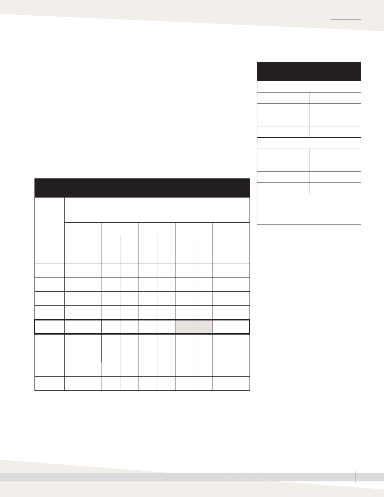
Table 23-2:
Gas pipe capacities for gas pressures of 0.5 psig (3.45 kPa) or less
Length of
pipe
ft m ft
Gas fl ow in piping in ft3/hr and m3/hr at pressure drop of 0.3" wc (0.07 kPa)
Nominal iron pipe diameter in inches (DN)
1/2" (DN15) 3/4" (DN20) 1" (DN25) 1¼" (DN32) 1½" (DN40)
3
/hr m3/hr ft3/hr m3/hr ft3/hr m3/hr ft3/hr m3/hr ft3/hr m3/hr
Specifi c gravity = 0.60
Table 23-1:
Specific gravity conversion factors
Natural gas
Specifi c gravity Factor
0.55 1.04
0.60 1.00
0.65 0.962
Propane gas
Specifi c gravity Factor
1.50 0.633
1.53 0.626
1.60 0.612
Note:
Use the above multiplying factor with Table:
23-2 when the specifi c gravity of gas is other
than 0.60 (natural gas) or 1.53 (propane).
10 3 132 3.7 278 7.9 520 14.7 1050 29.7 1600 45.3
20 6 92 2.6 190 5.4 350 9.9 730 20.7 1100 31.1
30 9 73 2.1 152 4.3 285 8.1 590 16.7 890 25.2
40 12 63 1.8 130 3.7 245 6.9 500 14.2 760 21.5
50 15 56 1.6 115 3.3 215 6.1 440 12.5 670 19.0
60 18 50 1.4 105 3.0 195 5.5 400 11.3 610 17.3
70 21 46 1.3 96 2.7 180 5.1 370 10.5 560 15.9
80 24 43 1.2 90 2.5 170 4.8 350 9.9 530 15.0
90 27 40 1.1 84 2.4 160 4.5 320 9.1 490 13.9
100 30 38 1.1 79 2.2 150 4.2 305 8.6 460 13.0
See example on page 24.
GTS INSTALLATION, OPERATION, AND MAINTENANCE MANUAL
23
Page 30

INSTALLATION
Gas Piping:
EXAMPLE
For this example, refer to the tables on Page 23.
To determine gas piping size, begin by calculating the cubic feet/hour (ft3/hr)
or m3/hr using the following formula:
Btuh (kW) input / calorifi c value of gas
Calorifi c values are:
• Natural gas: 1025 Btu/ft3 (10.6 kW-hr/m3)
• Propane: 2500 Btu/ft3 (25.9 kW-hr/m3)
For example, if you have a GTS-400 operating on natural gas, calculate the
ft3/hr or m3/hr as follows:
400,000 Btuh / 1025 Btu/ft3 = 390 ft3 per hour
117.2 kW / 10.6 kW-hr/m3 = 11.1 m3 per hour
If you need to run your gas piping 60 feet (18 m), see Table 23-2, and look
horizontally across the 60 ft (18 m) row until you locate the next highest value
above your calculated ft3/hr or m3/hr. In this example, you are looking for the
next highest value above 390 ft3/hr (11.05 m3/hr), which is 400 ft3/hr (11.3
m3/hr) and indicates the use of a 1¼" (DN32) pipe for this application.
Gas leak testing
• When leak-testing the gas supply piping
system, disconnect the humidifi er and its gas
shutoff valve during any pressure in excess
of 24" wc (6 kPa). Isolate the humidifi er from
the gas supply piping system by closing its
fi eld-installed manual shutoff valve during
any pressure not equal to 24" wc (6 kPa).
• With all burners running, check gas supply
pressure at the inlet pressure tap of the
combination gas control valve.
For North American models, the
recommended supply pressure is 7" wc
(1.75 kPa) for natural gas or 11" wc (1.83
kPa) for LP gas. Perform gas piping purging
as described in ANSI Z223.1 (latest edition)
or in Canada, CAN/CGA-B149 codes. The
minimum supply pressure is 6" wc (1 kPa) for
natural gas or LP gas.
For European models, the required supply
pressure is 20 or 25 mbar for natural gas
and 30, 37, or 50 mbar for propane gas.
Using the same example, if the specifi c gravity of your natural gas was 0.55
(instead of the 0.60 standard), see Table 23-2 for an adjustment factor.
In this case, the factor would be 1.04, which you multiply by the 390 ft3/hr
(11.05 m3/hr) value. This gives you a new value of 406 ft3/hr (11.49 m3/hr).
Referring again to Table 23-2, you see that for the same 60 ft (18 m) length,
you now need to use 1½" (DN40) pipe due to the change in the specifi c
gravity of the gas.
GTS INSTALLATION, OPERATION, AND MAINTENANCE MANUAL
24
Page 31
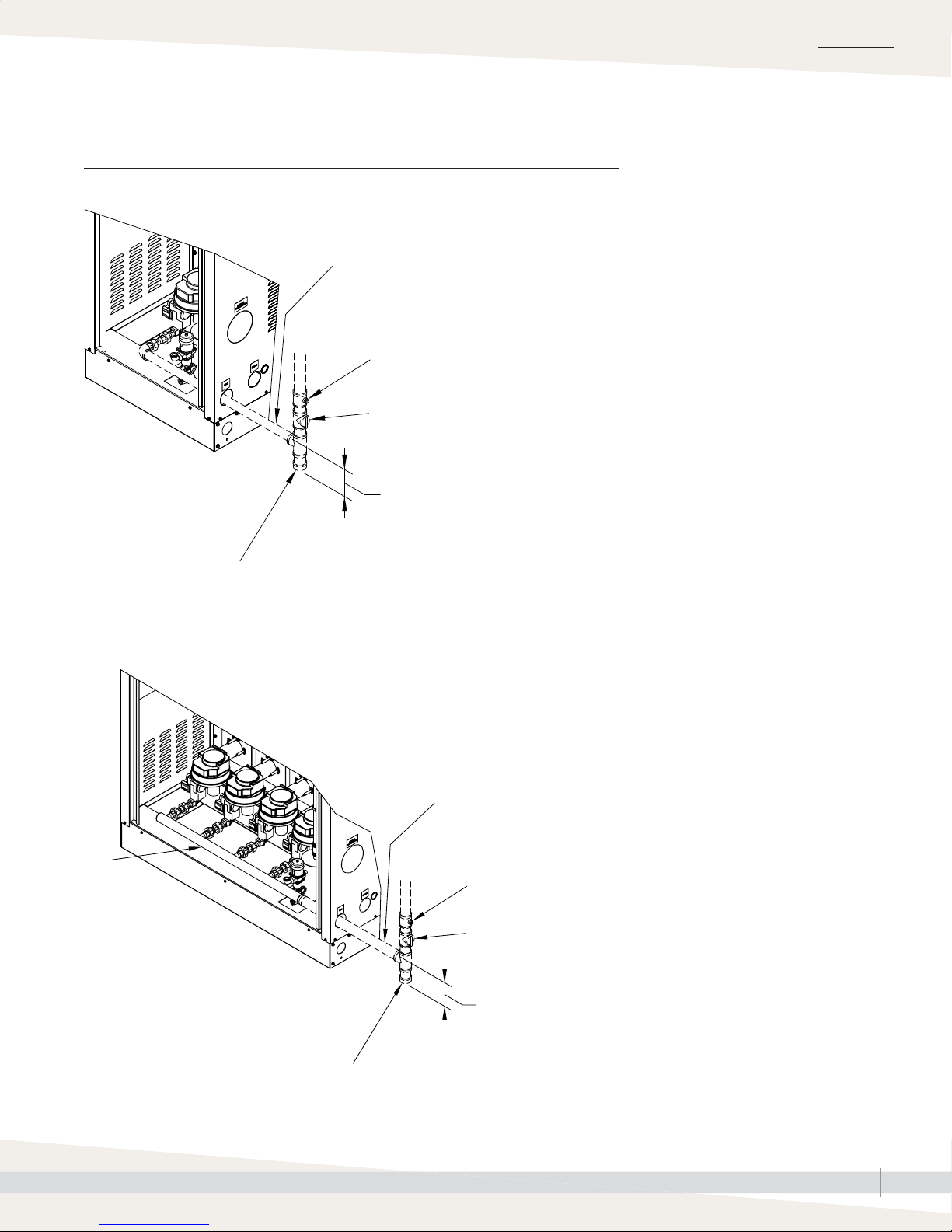
Gas Piping:
FIGURE 25-1: GTS GAS PIPING
Models 100, 200
OM-1236
INSTALLATION
1/2” pipe thread (DN15) piping
Plugged test gauge connection
Manual gas shutoff valve
Models 300-800
Gas manifold
(by DriSteem)
3” (76 mm) min.
Drip pocket
See Table 18-1 for
pipe size by model
Plugged test gauge
connection
Manual gas shutoff valve
Note: Dashed lines indicate supplied by installer
OM-1235
Drip pocket
3” (76 mm) min.
GTS INSTALLATION, OPERATION, AND MAINTENANCE MANUAL
25
Page 32
INSTALLATION
Combustion and ventilation air
The GTS humidifi er supports both room air and sealed combustion. See
Warning. Requirements and recommendations for each follow.
WARNING
ROOM AIR COMBUSTION
• All fuel burning equipment must be supplied with air for combustion of
the fuel. Suffi cient air must be provided to ensure there is not a negative
pressure in the equipment room or space.
• Provide adequate combustion and ventilation air in accordance with
Section 5.3, Air for Combustion and Ventilation, of the National Fuel
Gas Code, ANSI Z223.1 or applicable provisions of governing codes.
Canadian installations must be installed in accordance with sections 7.2,
7.3, and 7.4 of the CAN/CGA.B149 Installation Codes and all authorities
having jurisdiction.
• For proper and safe operation this appliance needs air for combustion and
ventilation. Do not block or obstruct air openings on the appliance, spaces
around the appliance, or air openings communicating with the appliance
area.
• Do not locate in a dusty environment.
• Do not block the fl ow of combustion and ventilation air. To provide for
necessary oxygen for proper combustion, openings must be provided
to allow outside air to enter the space where the humidifi er is located.
Enclosed spaces, such as equipment rooms, must be vented for combustion
air. The size of air openings must be based on all gas-burning equipment
installed in the space involved. Table 26-1 outlines four types of
locations, and the requirements of each.
Air for combustion
Air for combustion must not be
contaminated by halogen compounds,
which include fl uoride, chloride,
bromide, and iodide. These elements
are found in aerosol sprays, detergents,
bleaches, cleaning solvents, salts,
air fresheners, and other household
products.
When the GTS is located in an
environment with negative pressure
or toxic air, it must have sealed
combustion.
Failure to follow these instructions could
cause severe bodily injury or death.
Table 26-1:
Location of humidifier and required air openings
Location description Required air opening
Confi ned space with all air from inside the building;
conventional frame, brick or stone construction
with normal infi ltration (Note: this location rarely
provides enough air for higher capacity units.)
Confi ned space with all air from outside the
building through air ducts
Confi ned space with all air from outside the
building from through-wall openings only (no ducts)
Unconfi ned space with all air from outside the
building
* The minimum dimension of any opening is 3" × 3" (76 mm × 76 mm).
Two openings, 1 sq. in. (6.5 cm
opening per 1000 Btu/hr (293 W) input
The minimum free area of all openings
combined is 100 sq. in. (645 cm2).
Two openings, 2 ducts, 1 sq. in. (6.5 cm
per opening per 2000 Btu/hr (586 W)
input*
Two openings, 1 sq. in. (6.5 cm2) per
opening per 4000 Btu/hr (1172 W) input*
Same as confi ned space; all air from outside
the building
2
) per
2
)
GTS INSTALLATION, OPERATION, AND MAINTENANCE MANUAL
26
Page 33
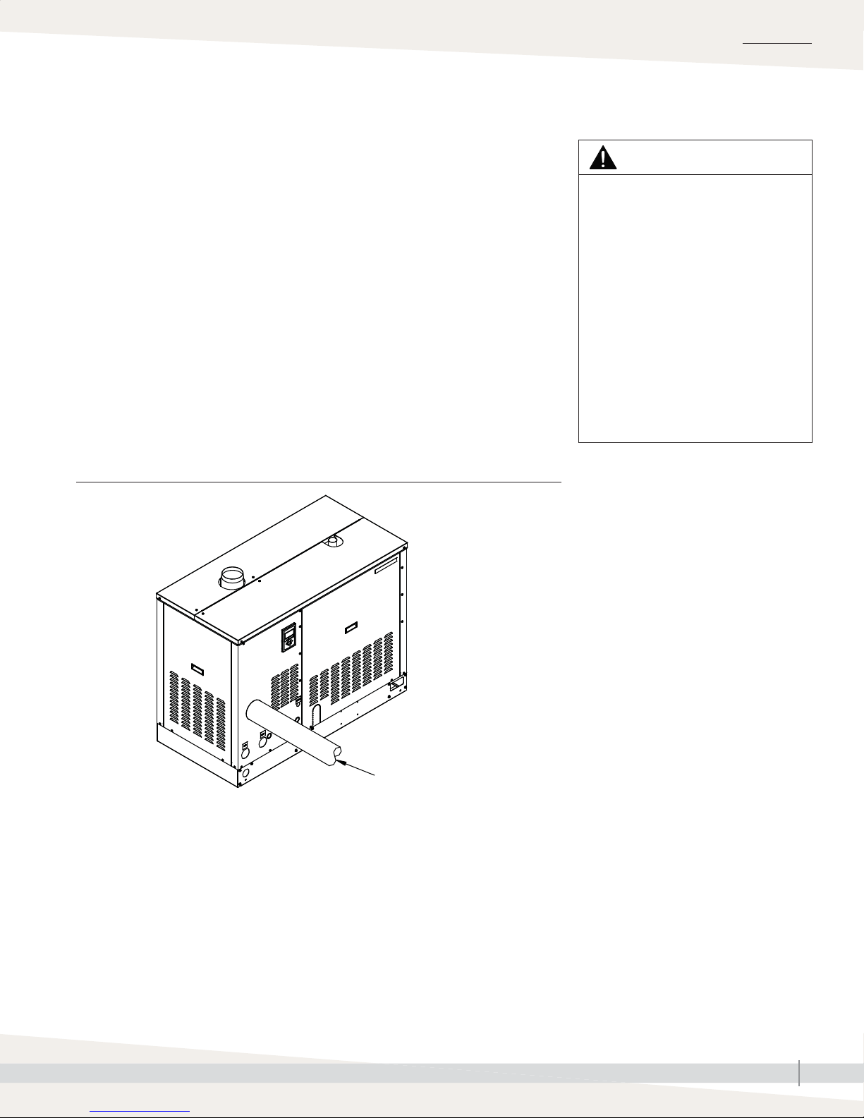
Combustion and ventilation air
SEALED COMBUSTION
The GTS supports sealed combustion using 4" (DN100) PVC or CPVC piping
(see Figure 27-1). All GTS models have a single point connection to the
blower inside the humidifi er shroud.
When running PVC or CPVC piping for sealed combustion, the maximum
allowable distance to the outdoor air source is 70' (21.3 m) including 7'
(2.1 m) equivalent length for each elbow. The outside air source can be
either a fi nal connection outside the building or a connection to an outdoor
air plenum within the building. When the combustion air origination point is
outside the building, the opening must be covered with a large mesh screen to
prevent the introduction of unwanted materials without restricting airfl ow.
If sealed combustion piping is less than 20 ft (6 m), we recommend insulating
piping to prevent condensation.
INSTALLATION
WARNING
Requirement for manifolding sealed
combustion piping runs
When installing sealed combustion
piping for more than one GTS
humidifi er, do not commonly manifold
multiple sealed combustion piping
runs without having the manifold
sized for the specifi c installation by
a licensed engineer. Failure to follow
these instructions could starve the GTS
humidifi er of combustion air resulting
in either the unit not being able to light
or high carbon monoxide (CO) levels,
which may cause severe personal injury
or death.
FIGURE 27-1: GTS OPTIONAL SEALED COMBUSTION CONNECTION
OM-1225
4" dia. (DN100) PVC or
CPVC combustion air intake
GTS INSTALLATION, OPERATION, AND MAINTENANCE MANUAL
27
Page 34

INSTALLATION
Vertical and horizontal venting
GUIDELINES (STACK CONNECTION)
• The GTS is a Fan Assisted Category I (natural draft) Appliance. Installations
where the vent terminates in a side wall of the building, or where the
overall horizontal run exceeds the overall vertical run require a power
venter. See Page 30.
• Maximum fl ue temperature under normal operating conditions is 400 °F
(205 °C) plus ambient.
• Maximum abnormal-operation fl ue temperature is 658 °F (348 °C) plus
ambient.
• Flue draft negative pressure greater than 0.2" wc (50 Pa) may cause
unacceptable post ignition.
• Vent piping must be UL or UL/CSA listed type B, B-W, or any other vent
type approved for a Category I appliance.
– Type B: Double wall construction, inner wall aluminum, outer wall
galvanized steel
– Type B-W: Same as type B except fabrication in oval shapes only
Do not use more than one type of venting per application Required
clearance for Type B and B-W vent piping is 1" (25 mm).
WARNING
Installation requirements
The humidifi er must be installed by
a qualifi ed technician and meet the
requirements of all governing codes.
Failure to follow these instructions could
cause severe bodily injury or death.
Note:
For European models, contact your distributor
for horizontal venting parts.
• Do not use vent equipment from more than one manufacturer.
• When connecting the humidifi er to a gas vent or chimney, installation must
be in accordance with Part 7, Venting of Equipment, of the National Fuel
Gas Code, ANSI Z223.1; or Section 7, Venting Systems and Air Supply
Appliances, of the CAN/CGA B149 Installation Codes; or National Gas
Safety Code (Installation & Use) Regulations (latest revision); governing
codes, and the vent manufacturer’s instructions.
• When applying the codes, reference also the venting manufacturer's
instructions, the service gas supplier's regulations, and the specifi c
instructions provided in this manual.
• Install a drip tee or fl ue box condensate drain. See Caution statement.
• The purpose of venting the gas humidifi er is to completely remove all
products of combustion and ventilation gases to the outside air.
• For vertical vent pipe terminations only: Do not reduce the vent diameter
and avoid short turns in the vent piping. Use the same size stack as the vent
furnished with the humidifi er. Maintain a minimum upward slope of 1/4"
per linear foot (2%) on all horizontal runs. Maintain proper support of vent
connections and joints. Observe clearances (in accordance with applicable
codes) from all combustible materials and install an approved cap for the
stack outlet. The bottom of the cap must be one stack diameter above the
top of the stack.
• Inspect for proper and tight construction. Remove any restrictions or
obstructions. An existing chimney may require cleaning.
CAUTION
Flue condensate removal
Install a drip tee or fl ue box condensate
drain for start-up fl ue condensate
removal. Failure to follow these
instructions could cause water to
accumulate in the fl ue box.
• For vertical vent pipe terminations only: Extend chimney or vent at least 3'
(1 m) above its passage through a roof and at least 2' (0.6 m) above any
ridge within 10' (3 m) of the chimney (governing codes apply).
• Do not connect this humidifi er to a chimney fl ue servicing a separate
appliance designed to burn solid fuel.
GTS INSTALLATION, OPERATION, AND MAINTENANCE MANUAL
28
Page 35

Vertical and horizontal venting
• Never connect this humidifi er to a chimney serving a fi replace, unless the
fi replace opening is permanently sealed off.
INSTALLATION
WARNING
• Code prohibits venting into an unlined masonry or concrete chimney.
• If this humidifi er is connected to a lined, masonry chimney, the chimney
must be sized and installed according to the provisions of the National
Fuel Gas Code or Canadian CAN/CGA.B149 requirements, or governing
codes.
• Vent connector serving this appliance shall not be connected into any
portion of mechanical draft systems operating under positive pressure.
• Add insulation to any roof or wall penetration vent connector that is
exposed to ambient temperatures of 30 °F (0 °C) or less, especially any
application using single-wall vent pipe as a connector.
• Do not insulate vent pipe exposed to outdoor weather conditions (e.g.,
above roof lines).
• Install vent piping as direct as possible, with a minimum number of turns or
elbows.
• Rigidly support the vent pipe every 5' (1.5 m) or less with hangers or straps
to ensure there is no movement after installation. The humidifi er vent box
should not support the weight of the vent piping.
• No portion of the vent system should extend into, or pass through, any
circulation air duct or plenum.
• The vent system must terminate above the roof surface per the National Fuel
Gas Code, CAN/CGA.B149, or National Gas Safety Code (Installation &
Use) Regulations (latest revision) requirements or governing codes, and must
include a UL or UL/CSA listed vent cap or roof assembly, unless prohibited
by governing codes. DriSteem recommends installing a high-wind vent cap
on all GTS humidifi ers.
Horizontal
For applications where the vent pipe
terminates in a vertical position, the
horizontal length of the vent and vent
connector must not exceed the height of
the vent system unless a power venter is
used. Failure to follow these instructions
could cause fl ue gases to exit the vent
piping, causing severe personal injury
or death.
• For vertical vent pipe terminations only: This humidifi er may be commonly
vented with other listed Category I gas-fi red appliances. Total input rates of
all appliances determines the vent size.
• Install and fi re-stop all vent pipe passing through fl oors, ceilings, and
walls with the proper clearances from combustible material according to
the National Fuel Gas Code, Canadian Standards CAN/CGA.B149, the
National Gas Safety Code (Installation & Use) Regulations (latest revision),
or governing codes.
• In replacement installation where an existing vent system may be used,
inspect the vent system for condition, size, type of vent material, and
height to meet the requirements in these instructions. When connecting the
humidifi er to a gas vent or chimney, the installation must be in accordance
with Part 7, Venting of Equipment, of the National Fuel Gas Code, ANSI
Z223.1; Section 7, Venting Systems and Air Supply Appliances, of the
CAN/CGA B149 Installation Codes; The National Gas Safety Code
(Installation & Use) Regulations (latest revision), governing building codes,
and the vent manufacturer’s instructions.
GTS INSTALLATION, OPERATION, AND MAINTENANCE MANUAL
29
Page 36
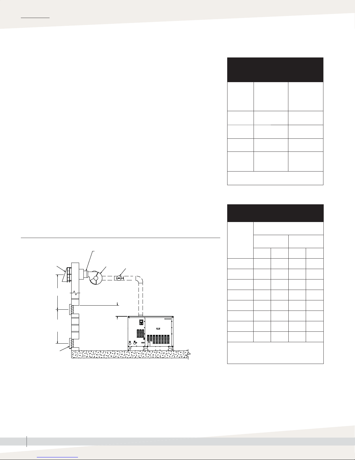
INSTALLATION
Vertical and horizontal venting
SPECIAL HORIZONTAL VENTING REQUIREMENTS
• Ensure that distances from vent terminal to adjacent public walkways,
buildings, and openable windows and building openings are consistent
with National Fuel Gas Code, ANSI Z223.1, CAN/CGA B149 Installation
Codes, National Gas Safety Code (Installation & Use) Regulations (latest
revision), or governing codes.
• In areas accessible to the public, vent terminal must be at least 7' (2.1 m)
above ground level to prevent burns from hot terminal surface.
• The vent terminal and air intake locations must be at suffi cient height above
ground level to prevent blocking by expected snowfall.
• Building materials must be protected from degradation by fl ue gases.
• Maintain minimum horizontal clearance of 4' (1.22 m) from electric meters,
gas meters, regulators, and relief equipment.
• Maximum equivalent length of vent pipe is 100' (30 m). Minimum
equivalent length of vent pipe is 10' (3 m). See power venter installation
manual for equivalent lengths of fi ttings.
• Vent box pressure must be –0.01" wc (–2.5 Pa). Set by adjusting power
venter and barometric damper with all burners running (see manufacturer's
instructions included with power venter and damper).
Table 30-1:
Equipment required for horizontal
venting
Field controls
Item
Power
venter
Barometric
damper
Vent hood SWH-1-5 (5") SWH-8
Electrical
ratings
Note: For European models, contact your
model number
for GTS models
100, 200, 300,
400
PVO-600 (5") PVE-1200 (8")
MG-1 (5") MG-1 (8")
120 VAC
60 Hz
2.1 A
distributor for horizontal venting parts.
Field controls
model number
for GTS models
500, 600, 700,
and 800
120 VAC
60 Hz
2.5 A
Table 30-2:
Recommended minimum vent sizes
FIGURE 30-1: GTS VENTING
Important: Seal the connection and all other vent
piping joints on the pressure side of the power venter.
Vent hood
Distance**
Air intake
3½' (1.07 m)
minimum
Air intake
Notes:
* Install a tee after the fi rst elbow from the humidifi er as shown. Use the open end of this tee for
the location of the barometric damper.
** Required distance between air intake and vent hood is defi ned by governing codes.
• Refer to power venter manual for clearance requirements relative to combustion air openings.
Power venter
X
Recommended
value for X
approximately
12" (305 mm)
Barometric draft control installed in tee*
OM-1209
Minimum vent size
Model
GTS-100 5 130 5 130
GTS-200 5 130 5 130
GTS-300 7 180 5* 130
GTS-400 7 180 5* 130
GTS-500 8 205 8 205
GTS-600 8 205 8 205
GTS-700 10 255 8* 205
GTS-800 10 255 8* 205
Note: For best results, make transition to
smaller vent diameter as close to the
power venter as possible.
Vertical vent Horizontal vent
inches mm inches mm
GTS INSTALLATION, OPERATION, AND MAINTENANCE MANUAL
30
Page 37

INSTALLATION
Dispersion:
SELECTING THE DISPERSION ASSEMBLY LOCATION
• Non-wetting distance is the dimension downstream from the leaving
side of the steam dispersion assembly to the point where wetting will
not occur, although wisps of steam may be present. This distance was
calculated during humidifi cation system design and is dependent on
several application parameters. To determine your dispersion assembly’s
non-wetting distance, consult your system’s design engineer or project
documentation. Non-wetting distance can also be calculated using
DriSteem’s DriCalc sizing and selection software, available at www.
dristeem.com. Note that your current design conditions may vary from
conditions used for system design.
• It is important that the dispersion assembly is positioned where the water
vapor being discharged is carried off with the airstream and is absorbed
before it can cause condensation or dripping in the duct.
• In general, the dispersion assembly is best placed where the air can most
readily absorb the moisture being added without causing condensation
at or after the unit. This normally is after the heating coil or where the air
temperature is highest.
• Place the dispersion assembly so that absorption occurs before the intake
of a high effi ciency fi lter. The fi lter can remove the visible moisture and
become waterlogged.
Selecting a location
• Place the dispersion assembly so absorption occurs before coming in
contact with any metal surface.
• Place the dispersion assembly so absorption occurs before fi re or smoke
detection devices.
• Place the dispersion assembly so absorption occurs before a split in the
duct. Otherwise, the dispersion assembly may direct more moisture into one
duct than the other.
• When draining dispersion condensate to an open drain, provide a 1"
(25 mm) gap between the condensate drain piping and the drain. Locate
air gap only in spaces with adequate temperature and air movement to
absorb fl ash steam; otherwise, condensing on nearby surfaces may occur.
GTS INSTALLATION, OPERATION, AND MAINTENANCE MANUAL
31
Page 38

INSTALLATION
Dispersion:
Interconnecting piping requirements
• The steam outlet on the humidifi er is sized to the output of the humidifi er.
DO NOT use interconnecting piping with an inside diameter smaller than
the humidifi er steam outlet.
• See the maximum steam carrying capacities and maximum piping lengths
in Table 33-1.
• See the steam loss data in Table 33-2.
• See the Table 37-1 for pitch of dispersion tubes and interconnecting piping
for single tube and multiple tube applications. See Table 42-1 for pitch
of interconnecting piping, dispersion tubes, and headers for Rapid-sorb
applications.
• If the humidifi er must be located higher than the dispersion assembly, use
the recommended installation shown in Figure 35-1.
• For single tube applications, see the capacities in Table 39-1.
CONNECTING TO DISPERSION ASSEMBLY WITH STEAM HOSE
• Support steam hose to prevent sags or low spots and to maintain a
minimum pitch of 2"/ft (15%) back to the humidifi er.
• Use DriSteem steam hose. Other manufacturers of steam hose may use
unacceptable release agents or material mixes that can affect humidifi er
system performance adversely. Using hose from alternative manufacturers
increases the possibility of tank foaming and accelerated aging. Foaming
causes condensate discharge at the dispersion assembly.
WARNING
Prevent pressure build-up in
evaporating chamber
The evaporating chamber is designed
as a nonpressurized vessel. Do not
restrict piping where steam exits the
humidifi er. Do not install a shut-off
valve on the piping connecting the
evaporating chamber to the steam
outlet.
Important:
Failure to follow the recommendations in this
section can result in excessive back pressure on
the humidifi er. This will result in unacceptable
humidifi cation system performance such as
leaking gaskets, blown water seals, erratic
water level control, and spitting condensate
from dispersion tubes.
mc_060210_0843
• Do not use steam hose in outdoor applications.
• Do not insulate steam hose. Insulation causes accelerated heat aging,
causing the steam hose to become hard and susceptible to failure due to
cracks.
CONNECTING TO DISPERSION ASSEMBLY WITH TUBING
• Support interconnecting piping between the humidifi er steam outlet and the
dispersion system with pipe hangers. Failure to properly support the entire
steam piping weight may cause damage to the humidifi er tank and void the
warranty.
• 90° elbows are not recommended; use two 45° elbows, 1' (0.3 m) apart.
• Insulate tubing to reduce the loss in output caused by condensation.
mc_060310_1145
GTS INSTALLATION, OPERATION, AND MAINTENANCE MANUAL
32
Page 39
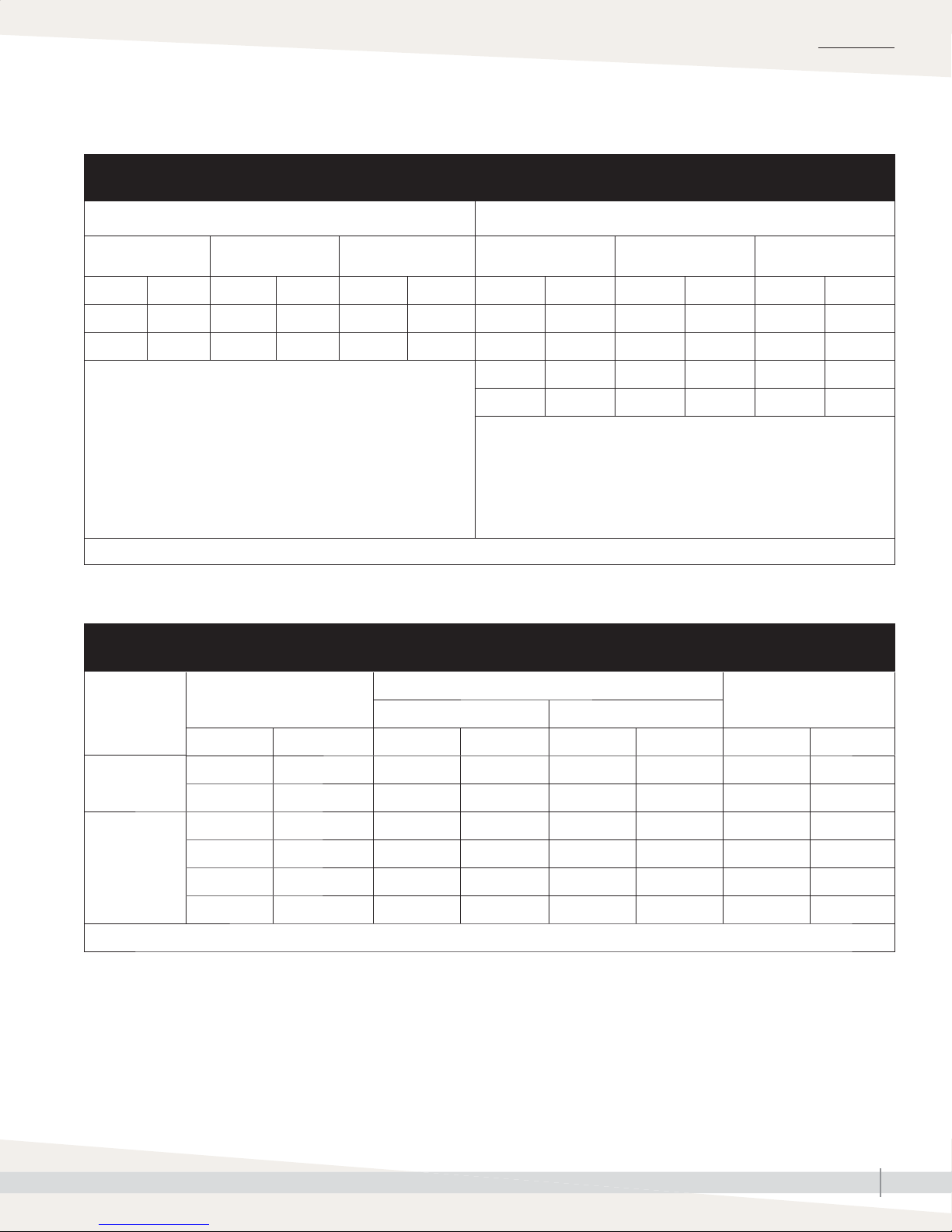
INSTALLATION
Dispersion:
Interconnecting piping requirements
Table 33-1:
Maximum steam carrying capacity and length of interconnecting steam hose or tubing
Steam hose
Hose I.D. Maximum capacity Maximum length
inches DN lbs/hr kg/h ft m inches DN lbs/hr kg/h ft m
1½ 40 150 68 10 3 1½ 40 150 68 20 6
2 50 250 113 10 3 2 50 220 100 30 9
1. When using steam hose, use DriSteem steam hose for best results.
Field-supplied hose may have shorter life and may cause foaming in
the evaporating chamber resulting in condensate discharge at the
dispersion assembly. Do not use steam hose for outdoor applications.
2. Maximum recommended length for steam hose is 10' (3 m). Longer
distances can cause kinking or low spots.
Note: Capacities and lengths in this table are based on total maximum pressure drop in hose or tubing of 5" wc (1250 Pa).
mc_091410_1050-GTS
1
2
Tubing size Maximum capacity
3 5 80 5450 204 80 24
4 5 100
3. Insulate tubing to minimize loss of capacity and effi ciency.
4. Developed length of tubing equals measured length plus 50% of measured
length, to account for fi ttings.
Longer tubing lengths are possible at capacities lower than listed
maximums. Consult factory.
5. Requires fl ange connection.
Copper or stainless steel tubing
3
5
750 340 100 30
Maximum developed
length
4
Table 33-2:
Steam loss of interconnecting steam hose or tubing
Description
Hose
Tubing
Note: Data based on an ambient air temperature of 80 °F (27 °C), fi berglass insulation, and copper tubing.
Nominal hose or tubing size
Noninsulated Insulated
inches DN lbs/hr/ft kg/h/m lbs/hr/ft kg/h/m inches mm
1½ 40 0.15 0.22 N/A N/A N/A N/A
2 50 0.20 0.30 N/A N/A N/A N/A
1½ 40 0.11 0.16 0.020 0.030 2.0 50
2 50 0.14 0.21 0.025 0.037 2.0 50
3 80 0.20 0.30 0.030 0.045 2.5 64
4 100 0.26 0.39 0.030 0.045 3.0 76
Steam loss
Insulation thickness
GTS INSTALLATION, OPERATION, AND MAINTENANCE MANUAL
33
Page 40
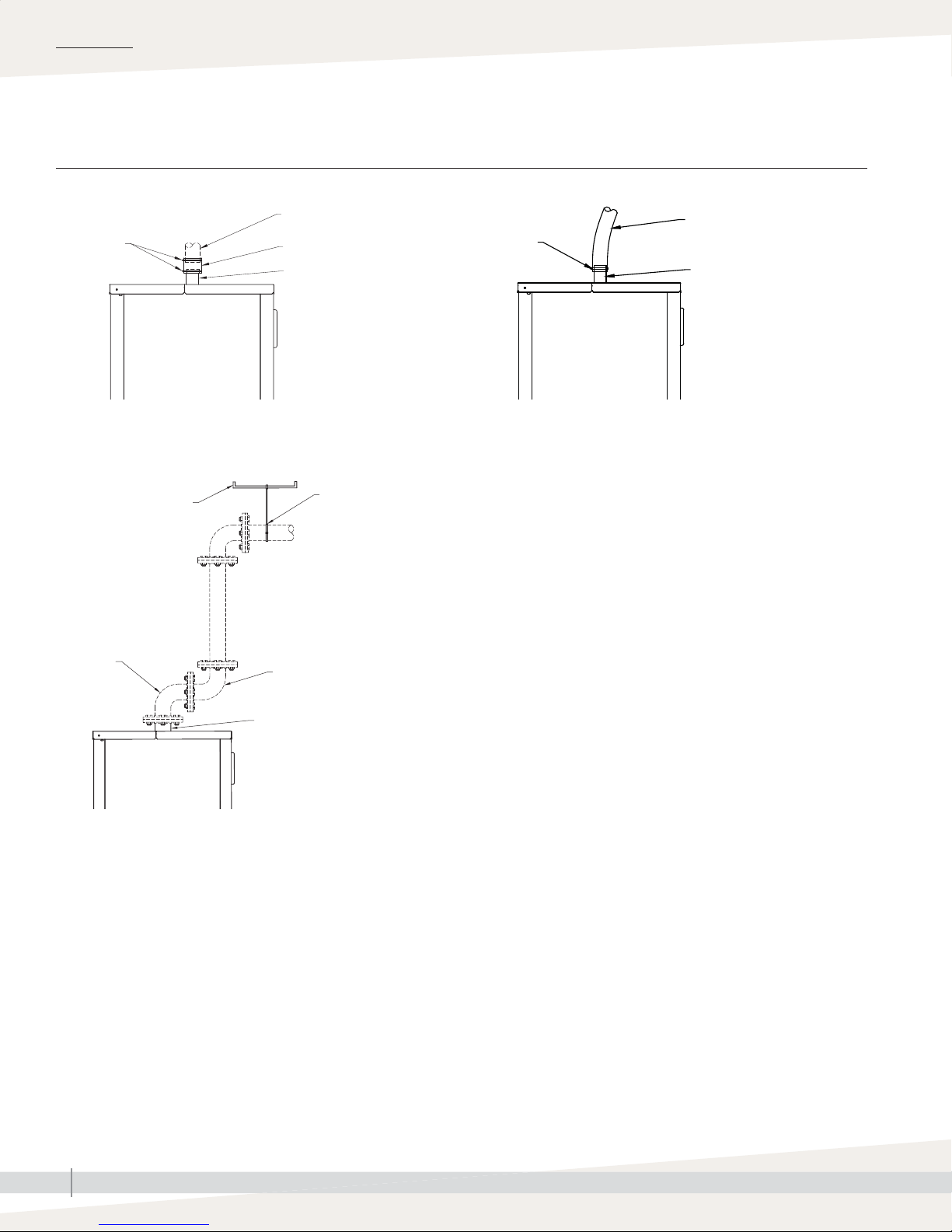
INSTALLATION
Steam outlet connectionsDispersion:
FIGURE 34-1: STEAM OUTLET CONNECTIONS
Tubing using hose cuff with clamps
Hose clamps
OM-1233
Flange connection
Support member
Tubing
6"-long (152 mm) hose cuff
Steam outlet connection
(tubing)
Support tubing from
above to prevent undue
pressure on humidifi er
outlet. Allow for thermal
expansion.
Hose connection
Steam hose
Hose clamp
Steam outlet connection
(tubing)
OM-1232
Notes:
• Dashed lines indicate provided by installer.
• Diameter of interconnecting steam hose or tubing must be equal to or
greater than the diameter of the steam outlet. Do not use steam hose or
tubing that is smaller than the steam outlet.
Swing arm
by installer
Directional arm (up, down,
right, left) by installer
Steam outlet connection
(fl ange)
OM-1234
GTS INSTALLATION, OPERATION, AND MAINTENANCE MANUAL
34
Page 41
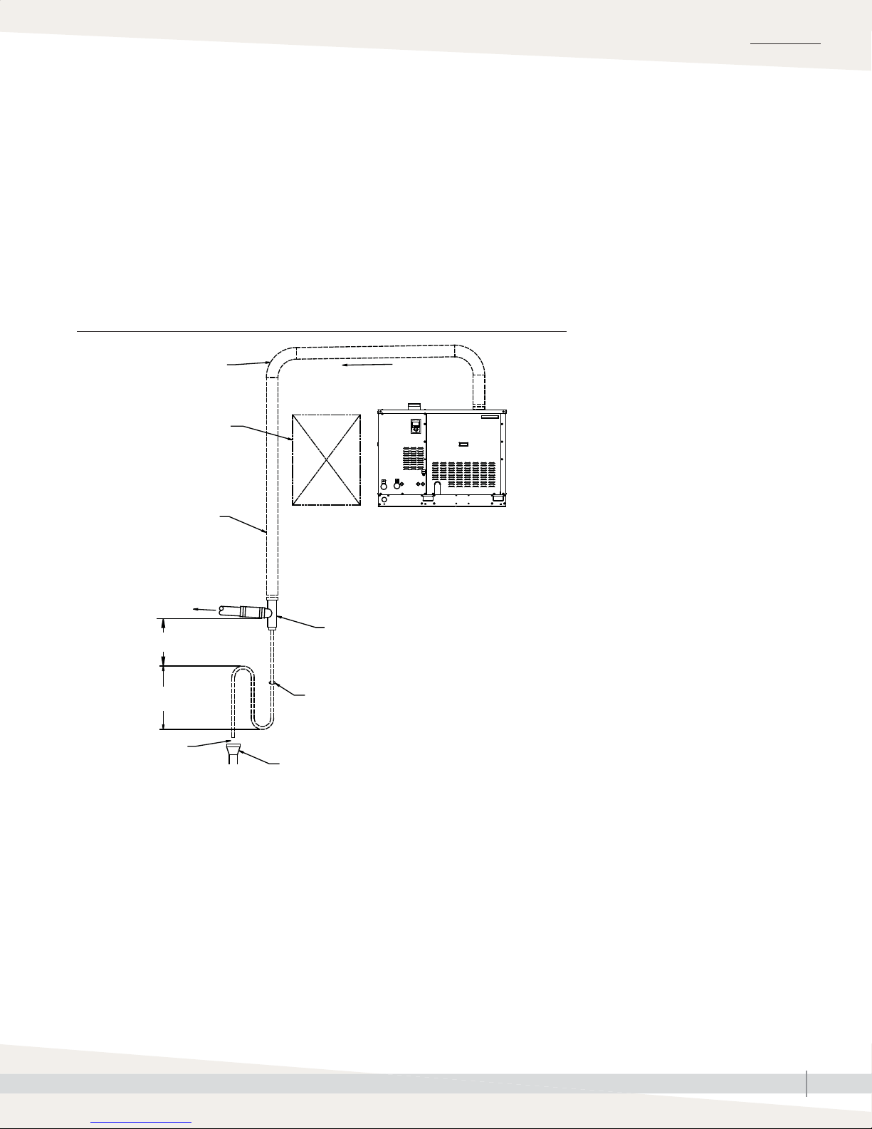
Drip tee installationDispersion:
Install a drip tee as shown below
• When the humidifi er is mounted higher than the dispersion assembly
• When interconnecting hose or piping needs to go over an obstruction
• When interconnecting piping runs are long
Important: Steam hose must be supported to prevent sagging or low spots.
FIGURE 35-1: DRIP TEE INSTALLATION (PIPING OVER AN OBSTRUCTION)
INSTALLATION
90° long sweep or
two 45° elbows
Obstruction
Insulate tubing to
reduce steam loss
To dispersion assembly
6" (150 mm) minimum
8" (200 mm) minimum
1" (25 mm) air gap
Notes:
• Locate air gap only in spaces with adequate temperature and air movement to absorb fl ash
steam, or condensing on nearby surfaces may occur. Refer to governing codes for drain pipe
size and maximum discharge water temperature.
• Support steam hose so there are no sags or low spots
• Dashed lines indicate provided by installer
3/4" (DN20)
Open drain required. See fi rst note below.
Pitch
OM-1210
GTS humidifi er
Tubing drip tee, by installer. DriSteem part
numbers for 304 stainless steel in-line tees:
• 1½" diameter (DN40): No. 162710
• 2" diameter (DN50): No. 162712
GTS INSTALLATION, OPERATION, AND MAINTENANCE MANUAL
35
Page 42

INSTALLATION
Dispersion:
INSTALLATION
Single tube and multiple tube
See the following pages for detailed drawings and notes for installing single
tube and multiple tube dispersion assemblies.
DISPERSION TUBE MOUNTING
• Orient dispersion tube(s) so the tubelets (steam orifi ces) point up.
• See Table 37-1 for dispersion tube pitch requirements.
• If mounting the humidifi er above the level of the dispersion tube(s), see
Figure 35-1.
CONDENSATE DRAIN PIPING
• Minimum diameter (ID) for draining from one or two dispersion tubes:
3/4" (DN20)
• Minimum diameter (ID) for draining from three or more dispersion tubes:
1" (DN25)
• Condensate drain piping must be rated for 212 °F (100 °C) continuous
operating temperature.
• Condensate drain line must be piped as shown in the fi gures on the
following pages. Provide a 6" (152 mm) drop prior to a 5" (127 mm)
water seal to ensure drainage of condensate from the header and to keep
steam from blowing out of the drain line
Important:
Failure to follow the recommendations in this
section can result in excessive back pressure on
the humidifi er. This will result in unacceptable
humidifi cation system performance such as
leaking gaskets, blown water seals, erratic
water level control, and spitting condensate
from dispersion tubes.
mc_060210_0843
• After the water seal, run the drain line to an open drain with a 1"
(25 mm) vertical air gap. Cut the drain line at a 45° angle on the end
above the drain to permit a direct stream of water into the drain pipe
while maintaining a 1" (25 mm) air gap. Locate air gap only in spaces
with adequate temperature and air movement to absorb fl ash steam, or
condensing on nearby surfaces may occur.
• All drain lines must be installed and sized according to governing codes.
GTS INSTALLATION, OPERATION, AND MAINTENANCE MANUAL
36
Page 43

INSTALLATION
Single tube and multiple tubeDispersion:
Table 37-1:
Pitch of dispersion tubes and interconnecting piping for single tube or multiple tube evaporative dispersion units*
Condensate
drain
Without
drain
With
drain
Notes:
* When piping over an obstruction, see the drip tee installation illustration Figure 35-1.
• Assemble multiple dispersion tubes or use a Rapid-sorb or Ultra-sorb dispersion assembly to accommodate maximum humidifi er load.
• The smallest GTS humidifi er steam outlet is 2" (DN50). Install an adaptor manifold if using multiple 1½" (DN40) dispersion tubes. See Table
33-1.
Type of
interconnecting
piping
Steam hose
Tubing
Steam hose
Tubing
Diameter of dispersion tube and
interconnecting piping
1½" (DN40)
2" (DN50)
1½" (DN40)
2" (DN50)
1½" (DN40)
2" (DN50)
1½" (DN40) 1/2"/ft (5%)
2" (DN50) 1/4"/ft (2%)
Pitch of interconnecting
piping toward humidifi er
2"/ft (15%)
1/8"/ft (1%)
2"/ft (15%)
Pitch of
dispersion tube(s)
2"/ft (15%)
toward humidifi er
1/8"/ft (1%)
toward
condensate
drain
Pitch of
condensate drain
No drain
1/4"/ft (2%)
toward fl oor drain or
toward humidifi er if
humidifi er is below
dispersion unit
GTS INSTALLATION, OPERATION, AND MAINTENANCE MANUAL
37
Page 44
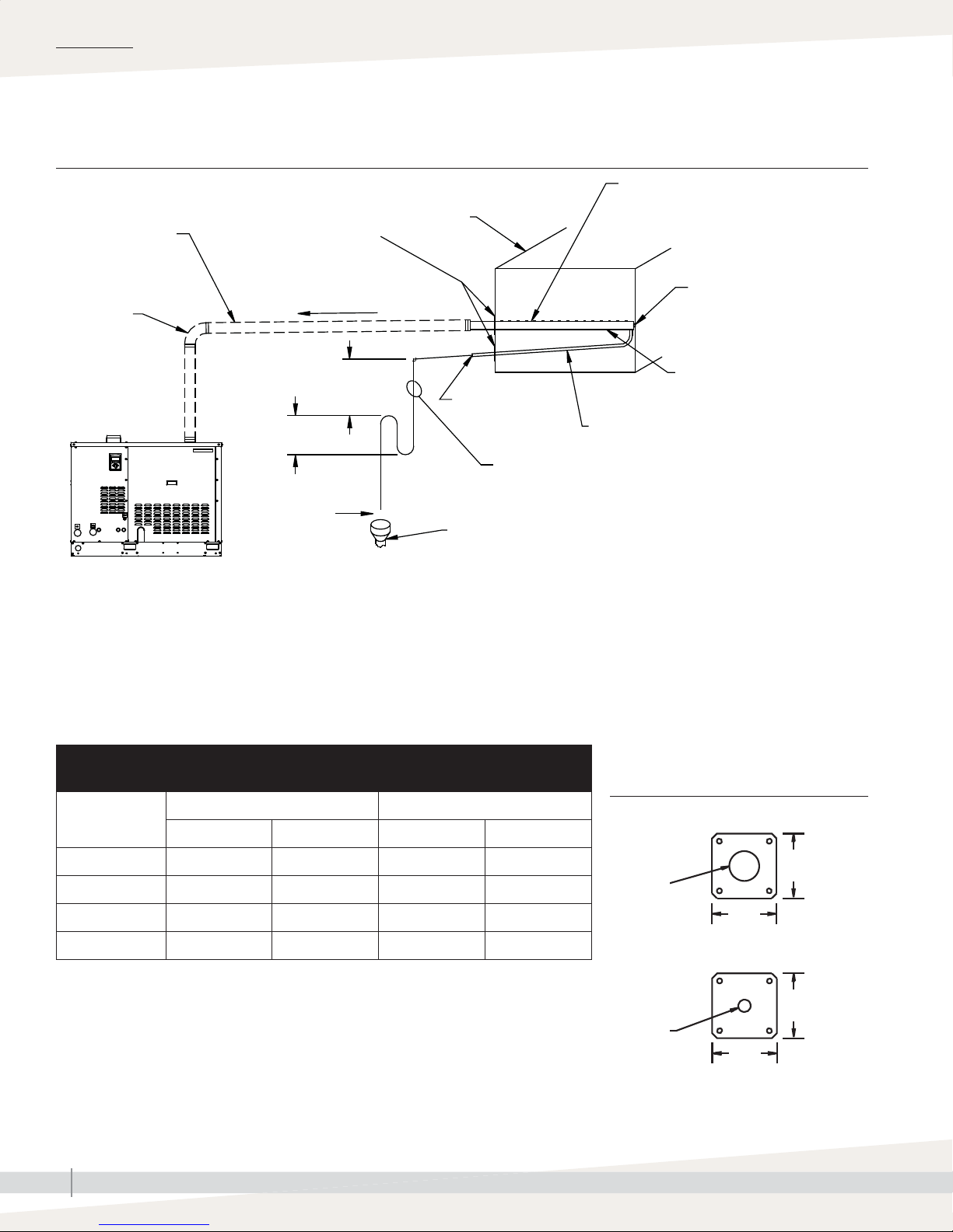
INSTALLATION
Single tube and multiple tubeDispersion:
FIGURE 38-1: SINGLE TUBE DISPERSION WITH CONDENSATE WASTED TO FLOOR DRAIN
Steam hose or tubing.
Insulate tubing to reduce
steam loss. Do not
insulate steam hose.
Secure and seal
escutcheon plates
Duct
Dispersion tube
90° long
sweep or two
45° elbows
GTS humidifi er
Notes:
1. Locate air gap only in spaces with adequate temperature and air movement to absorb fl ash steam, or condensing on nearby surfaces my occur.
Refer to governing codes for drain pipe size and maximum discharge water temperature.
2. Assemble multiple dispersion tubes or use a Rapid-sorb or Ultra-sorb dispersion assembly where necessary to accommodate maximum humidifi er load.
3. The smallest GTS humidifi er steam outlet is 2" (DN50). Install an adaptor manifold if using multiple 1½" (DN40) dispersion tubes. See also Table 37-1.
4. Pitch steam hose or tubing toward humidifi er:
– 2"/ft (15%) when using steam hose
– 1/2"/ft (5%) when using 1½" tubing
– 1/4"/ft (2%) when using 2" tubing
5. Dashed lines indicate provided by installer
Water seal
5" (127 mm)
OM-1212a
Pitch
(see Notes)
6" (152 mm)
recommended
1" (25 mm)
air gap
3/8" (M10) mounting nut
Pitch tube toward drain
1/4" (DN8) pipe
thread
Condensate drain tube, by installer, minimum 3/4" (DN20);
must be suitable for 212 °F (100 °C) water
Open drain required. See Note 1 below.
1/2" (DN15) O.D. condensate drain tube;
pitch 1/4"/ft (2%)
1/8"/ft (1%)
Table 38-1:
Dispersion tube and condensate drain escutcheon plate dimensions
for 1½" (DN40) tube for 2" (DN50) tube
inches mm inches mm
A 1.51 38 2.03 52
B 3.25 83 5.00 127
C 0.75 19 0.75 19
D 3.25 83 3.25 83
GTS INSTALLATION, OPERATION, AND MAINTENANCE MANUAL
38
FIGURE 38-2: DISPERSION TUBE AND
CONDENSATE DRAIN ESCUTCHEON
PLATES
Dispersion tube plate
B
A
(diameter)
B
Condensate drain plate
D
C
(diameter)
D
OM-351c
Page 45
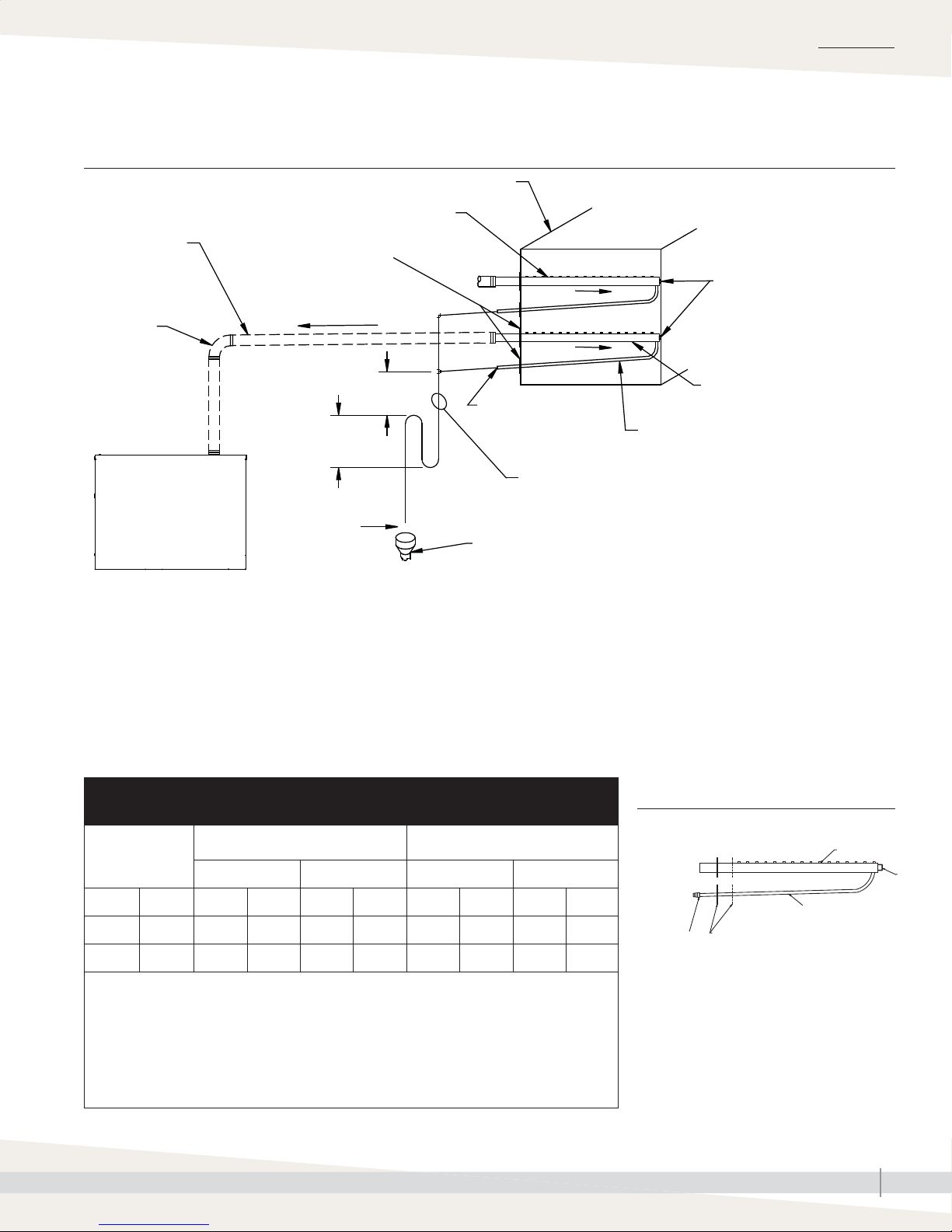
Single tube and multiple tubeDispersion:
FIGURE 39-1: SINGLE TUBE WITH CONDENSATE RETURNED TO HUMIDIFIER
Duct
Dispersion tube
INSTALLATION
Steam hose or
tubing
90º long
sweep
or two 45°
elbows
GTS humidifi er
Notes:
1. Assemble multiple dispersion tubes or use a Rapid-sorb or Ultra-sorb dispersion assembly where necessary
to accommodate maximum humidifi er load.
2. The smallest GTS humidifi er steam outlet is 2" (DN50). Install an adaptor manifold if using multiple 1½"
(DN40) dispersion tubes. See also Table 37-1.
3. Pitch steam hose or tubing toward humidifi er:
– 2"/ft (15%) when using steam hose
– 1/2"/ft (5%) when using 1½" (DN40) tubing
– 1/4"/ft (2%) when using 2" (DN50) tubing
4. Dashed lines indicate provided by installer
1/2" (13 mm)
air vent
Secure and seal
escutcheon plates
Pitch (see Notes)
6" (152 mm)
minimum
H (see Table 16-1)
OM-1215b
6" (152 mm)
minimum
Pitch
Pitch
1/4" pipe thread (DN8)
1/2" (DN15) O.D. condensate drain tube,
pitch 1/4"/ft (2%)
5" (127 mm)
water seal
Condensate drain tube, by installer, 3/4" DN20 minimum. Return line piping
material must be suitable for 212 °F (100 °C) water. Note: Condensate may
be returned to the humidifi er or wasted to a drain. See the previous page for
piping condensate to a drain.
Mounting nut, 3/8" (M10)
Pitch tube toward drain
1/8"/ft (1%)
Table 39-1:
Single dispersion tube capacities*
Insulated
Tube size
inches DN lbs/hr kg/h lbs/hr kg/h lbs/hr kg/h lbs/hr kg/h
1½ 40 29 13.2 65 29.5 28 12.7 62 28.2
2 50 65 29.5 97 44.1 62 28.2 93 42.3
Notes:
* If face width is <19" (483 mm), tube capacity may be reduced. Consult DriSteem or see
DriCalc for the correct capacity.
• Single dispersion tube available with face width between 6" (152 mm) up to 120" (3048 mm)
in 1" (25 mm) increments.
• Hose kits are available that include dispersion tube, 10 ft (3 m) of steam hose, and hardware
• The smallest GTS humidifi er steam outlet is 2" (DN50). Install an adaptor manifold if using
multiple 1½" (DN40) dispersion tubes.
(High-Effi ciency Tubes)
Without drain With drain Without drain With drain
Uninsulated
FIGURE 39-2: SINGLE TUBE DISPERSION
WITH CONDENSATE DRAIN
Thermal-resin tubelets
(steam orifi ce inserts)
1/4" (DN8)
pipe thread
end
GTS INSTALLATION, OPERATION, AND MAINTENANCE MANUAL
Movable escutcheon plate. Plate
can be mounted within limits of
2.5" (64 mm).
Mounting
bracket
1/2" O.D. (DN15)
condensate drain
OM-351b
39
Page 46
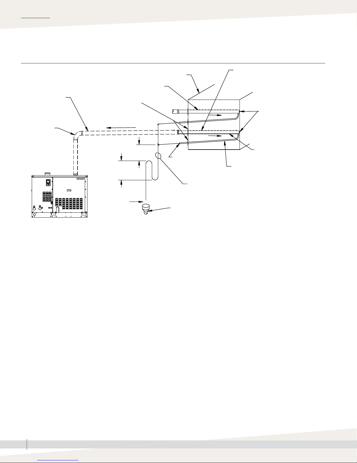
INSTALLATION
Single tube and multiple tubeDispersion:
FIGURE 40-1: MULTIPLE TUBES WITH CONDENSATE WASTED TO FLOOR DRAIN
Duct
Dispersion tube
Steam hose or tubing
90° long sweep
or two 45°
elbows
GTS humidifi er
OM-1215a
Notes:
1. Assemble multiple dispersion tubes or use a Rapid-sorb or Ultra-sorb dispersion assembly where necessary to accommodate maximum humidifi er load.
2. The smallest GTS humidifi er steam outlet is 2" (DN50). Install an adaptor manifold if using multiple 1½" (DN40) dispersion tubes. See also Table 37-1.
3. Pitch steam hose or tubing toward humidifi er:
– 2"/ft (15%) when using steam hose
– 1/2"/ft (5%) when using 1½" (DN40) tubing
– 1/4"/ft (2%) when using 2" (DN50) tubing
4. Dashed lines indicate provided by installer
Secure and seal
escutcheon plates
Pitch (see Notes)
(152 mm)
Water seal
5" (127 mm)
1" (25 mm)
air gap
Pitch
Pitch
6"
1/4" (DN8) pipe thread
Condensate drain tube provided by installer,
3/4" (DN20) minimum
Open drain required.
Locate air gap only in spaces with adequate temperature and air
movement to absorb fl ash steam, or condensing on nearby surfaces
may occur. Refer to governing codes for drain pipe size and maximum
discharge water temperature.
Dispersion tube
Mounting nut, 3/8" (M10)
Pitch tube toward drain
1/8"/ft (1%)
1/2" (DN15) O.D. condensate drain tube,
pitch 1/4"/ft (2%)
GTS INSTALLATION, OPERATION, AND MAINTENANCE MANUAL
40
Page 47

INSTALLATION
Dispersion:
GENERAL INSTALLATION INSTRUCTIONS
Rapid-sorb
Before you begin installation, read all dispersion instructions in this manual.
• Unpack shipment and verify receipt of all Rapid-sorb components with
packing list. Report any shortages to DriSteem factory immediately. The
components typically include the following:
– Multiple dispersion tubes
– Header
– 3/4" × 2" (19 mm × 51 mm) L-bracket
– A single duct escutcheon plate the size of the header
– Slip couplings or hose cuffs and clamps.
– Accessories such as duct plates, slip couplings, or hose cuffs (in plastic
bag)
– Bolts and washers for mounting dispersion tubes to bracket (in end of
tubes or packaged in a bag with other accessories)
– Tubes, header, and L-bracket are tagged with customer requested
identifi cation number written on each component.
• When choosing a location for installation, select a location that provides
necessary access in and around ductwork or air handler.
• Rapid-sorb is typically installed centered side to side in duct, or across face
of coil in air handler.
• Center line of outer dispersion tubes should never be closer than 4.5"
(114 mm) from side of ductwork or air handler wall.
Important:
Failure to follow the recommendations in this
section can result in excessive back pressure on
the humidifi er. This will result in unacceptable
humidifi cation system performance such as
leaking gaskets, blown water seals, erratic
water level control, and spitting condensate
from dispersion tubes.
mc_060210_0843
Table 41-1:
Rapid-sorb tube capacities*
Tube
diameter
inches DN lbs/hr kg/h lbs/hr kg/h
1½ 40 43 19.5 40 18.2
2 50 80 36.4 77 35
* Capacities shown are for horizontal airfl ow.
See DriCalc for vertical airfl ow capacities.
If face height is <22” (559 mm), tube
quantity per panel may need to increase to
compensate for reduced capacity of short
tubes. Consult DriSteem or see DriCalc for
the correct calculation.
Insulated
(High-Effi ciency
Tubes)
Uninsulated
• Rapid-sorbs are provided with an L-bracket for installation:
– L-brackets 50" (1270 mm) or shorter have a hole 4" (102 mm) from
each end for mounting L-bracket to duct or air handler wall.
– L-brackets longer than 50" (1270 mm) have an additional hole in center
of L-bracket.
– Important: Before marking and drilling holes in duct or air handler,
refer to ALL pitch requirements for the Rapid-sorb assembly you received
(see Table 42-1). Size, quantity, and location of penetrations are
determined by specifi c dimensions and confi guration of Rapid-sorb
assembly you received.
Note: Hardware for mounting L-bracket to duct or air handler wall and
hardware for header support bracket is not provided.
• The Rapid-sorb instructions are for the most typical Rapid-sorb installations
— installed in a duct horizontal airfl ow with Rapid-sorb header either inside
or outside of duct. See DriCalc Installation Guides library or contact your
representative/distributor or DriSteem for installation instructions for air
handler or vertical airfl ow applications.
Table 41-2:
Rapid-sorb header capacities
Header capacity Header diameter
lbs/hr kg/h inches DN
≤ 250 ≤ 113 2 50
251-500 114-227 3 80
501-800 228-363 4 100
GTS INSTALLATION, OPERATION, AND MAINTENANCE MANUAL
41
Page 48

INSTALLATION
Rapid-sorbDispersion:
PITCH REQUIREMENTS
• When installing Rapid-sorb with header outside a horizontal airfl ow duct,
consider the following pitch issues:
– For 1½" (DN40) dispersion tubes, use a fastener of suffi cient length to
accommodate 1/8"/ft (1%) pitch requirements toward the 3/4" pipe
thread (DN20) header drain fi tting.
– For 2" (DN50) dispersion tubes, bracket can be mounted fl ush to
ductwork. The 1/8"/ft (1%) pitch typically can be accomplished in
length of hose cuffs used to connect tubes to header.
• See the table below and the drawings on the following pages for pitch
requirements.
Table 42-1:
Pitch of interconnecting piping, dispersion tubes, and headers for Rapid-sorb evaporative dispersion units
Airfl ow
Horizontal
Vertical
Type of
interconnecting piping
Steam hose 1½" (DN40), 2" (DN50)
Tubing
Steam hose 1½" (DN40), 2" (DN50)
Tubing
Diameter of
interconnecting piping
1½" (DN40), 2" (DN50),
3" (DN80), 4" (DN100),
5" (DN125), 6" (DN150)
1½" (DN40), 2" (DN50),
3" (DN80), 4" (DN100),
5" (DN125), 6" (DN150)
Pitch of
interconnecting piping
2"/ft (15%)
toward Rapid-sorb
1/8"/ft (1%)
toward Rapid-sorb
2"/ft (15%)
toward Rapid-sorb
1/8"/ft (1%)
toward Rapid-sorb
Pitch of
dispersion tubes
Vertically plumb
2"/ft toward header
Pitch of
header
1/8"/ft (1%) toward
condensate drain
1/8"/ft (1%) toward
condensate drain
GTS INSTALLATION, OPERATION, AND MAINTENANCE MANUAL
42
Page 49
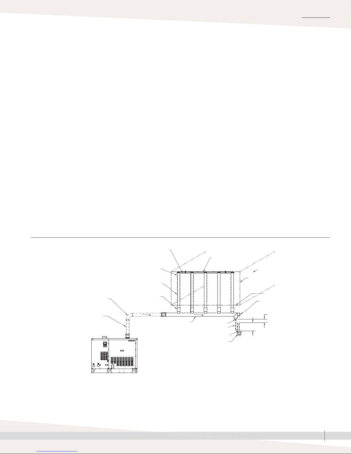
INSTALLATION
Rapid-sorbDispersion:
RAPID-SORB HEADER OUTSIDE OF DUCT (HORIZONTAL AIRFLOW)
1. Locate and cut holes in ductwork for dispersion tubes. Use L-bracket as a
template to locate holes on duct floor.
2. Temporarily, loosely suspend or support header below final location —
vertical balance point of the dispersion tube length dictates where header
should be suspended or supported temporarily.
3. Mount dispersion tubes to header with provided connector, either a slip
coupling or a hose cuff.
• When installing slip couplings for 1½" (DN40) dispersion tubes, take
care not to shear O-rings.
• Set slip coupling on header stub or dispersion tube so O-ring is resting
on face of tubing.
• Rotate slip coupling as you push them onto tubing.
• O-rings are lubricated at factory. If additional lubrication is necessary,
DO NOT use a petroleum-based lubricant.
4. Position flange of L-bracket so it is upstream of tubes when assembly is
raised and fastened into position. Fasten L-bracket to end of dispersion
tubes with provided bolt, lock washer, and flat washer.
Continued
Note:
See Figure 43-1 for steam supply and
condensate drain line connection instructions.
FIGURE 43-1: RAPID-SORB WITH HEADER OUTSIDE THE DUCT, HORIZONTAL AIRFLOW
Position L-bracket so that fl ange is upstream of dispersion tubes.
This drawing shows the L-bracket positioned for airfl ow back to front
Dispersion tube
Point tubelets (steam orifi ces) perpendicular to airfl ow
90° long sweep or two 45° elbows
Steam hose or tubing
GTS humidifi er
* Pitch steam hose or tubing toward Rapid-sorb:
– 2"/ft (15%) when using steam hose
– 1/8"/ft (1%) when using tubing
Slip coupling
or hose cuff
Pitch*
Pitch header toward
drain 1/8"/ft (1%)
OM-1214
Pitch*
3/4" pipe thread
(DN20) condensate drain
3/4" (DN20) copper
1" (25 mm) air gap
Open drain required.
Locate air gap only in spaces with adequate temperature and air
movement to absorb fl ash steam, or condensing on nearby surfaces
may occur. Refer to governing codes for drain pipe size and maximum
discharge water temperature.
Stainless steel support
by DriSteem
Airfl ow
Duct
Support bracket
Secure and seal
escutcheon plates
2" (51 mm)
recommended
5" (127 mm)
GTS INSTALLATION, OPERATION, AND MAINTENANCE MANUAL
43
Page 50

INSTALLATION
Rapid-sorbDispersion:
5. Before tightening L-bracket bolts to dispersion tubes:
• For 1½" (DN40) dispersion tubes:
– Dispersion tube will rotate in slip coupling. Verify that dispersion tube
orifi ces are directed perpendicular to airfl ow.
– Dispersion tube and slip coupling must be fully engaged onto header
stub for O-rings to provide a seal.
• For 2" (DN50) dispersion tubes:
Before securing hose cuff in place with hose clamps on dispersion
tube and header stub, verify that dispersion tube orifi ces are directed
perpendicular to airfl ow.
6. Slide assembly up until L-bracket aligns with mounting holes in duct.
• For 1½" (DN40) dispersion tubes:
– Header pitch is duplicated in L-bracket.
– Dispersion tube and slip coupling must be fully engaged on header
stub for O-rings to provide a seal.
– High end of L-bracket can be fastened tightly to duct or air handler.
– On low end of L-bracket, fastener must be long enough to
compensate for pitch, and a nut should be provided and secured on
both sides of L-bracket and duct or air handler for stability.
• For 2" (DN50) dispersion tubes:
– Fasten bracket to top of duct, and use hose cuffs to compensate for
pitch of header.
– Before securing hose cuff in place with hose clamps on dispersion
tube and header stub, verify that header pitch of 1/8"/ft (1%)
toward drain, is maintained.
7. Permanently secure both ends of the header and verify that the header
pitch, 1/8"/ft (1%) toward drain, is maintained.
8. Verify that all fasteners are secure:
• L-bracket to duct
• Dispersion tubes to L-bracket
• Hose clamps on 2" (DN50) tubes
9. Secure and seal dispersion tube escutcheon plate and condensate drain
tube escutcheon plate around respective tubes, if applicable.
GTS INSTALLATION, OPERATION, AND MAINTENANCE MANUAL
44
Page 51
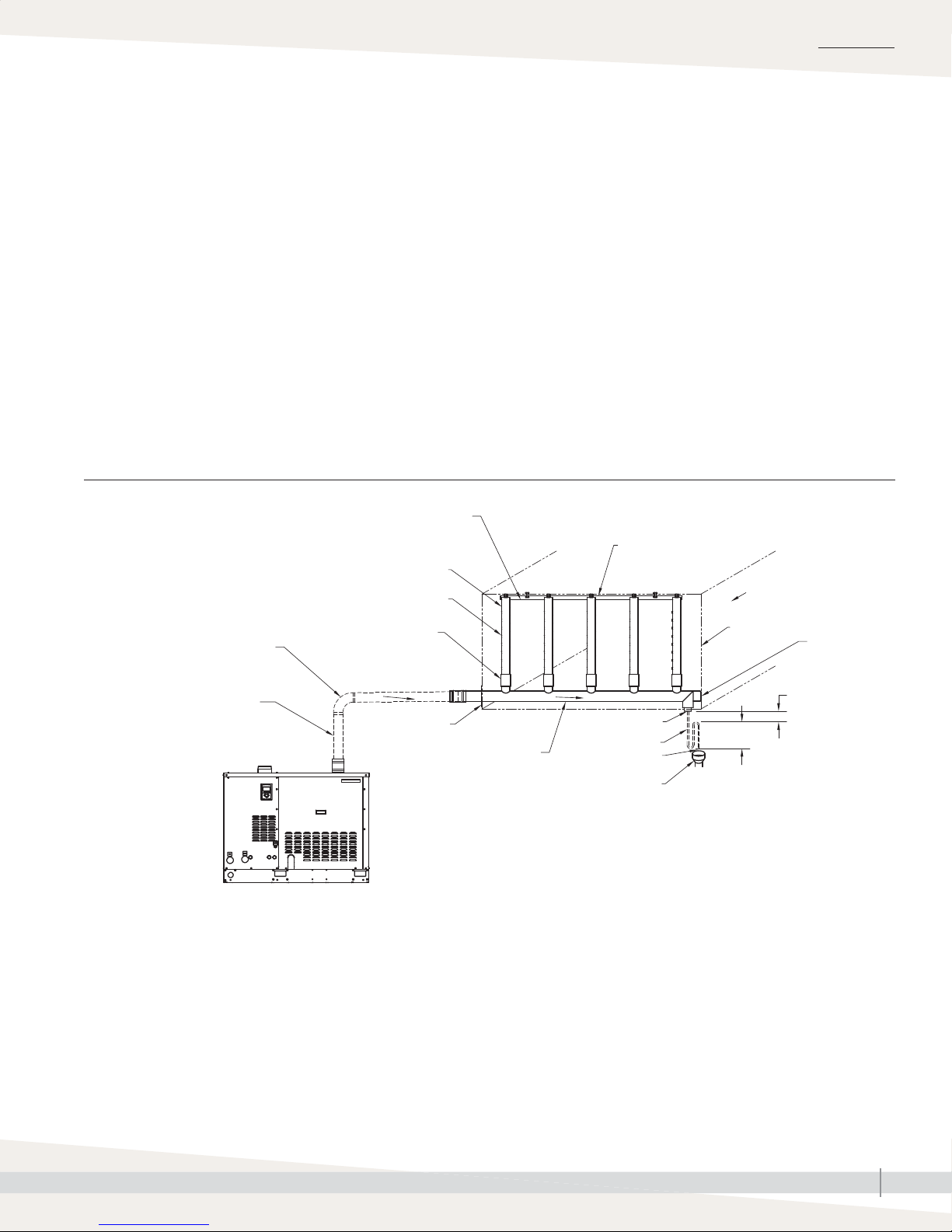
Rapid-sorbDispersion:
RAPID-SORB HEADER INSIDE OF DUCT (HORIZONTAL AIRFLOW)
1. Locate and cut the holes in ductwork or air handler for steam header
penetration, condensate drain piping, and header support bracket fastener.
Allow 1/8"/ft (1%) header pitch toward the support bracket when you drill
the hole for the header support bracket fastener.
2. Loosely fasten the header in place.
3. Rotate the header 90° so the header stubs point horizontally in the duct.
When installing in an air handler, the rotation of the header is often less
than 90°. Typically, due to the condensate drain piping requirements, the
header can be set on the fl oor of the air handler, assembled in the vertical
position, and then raised and mounted in place.
Continued
FIGURE 45-1: RAPID-SORB HEADER INSIDE THE DUCT, HORIZONTAL AIRFLOW
INSTALLATION
Position L-bracket so that fl ange is upstream of dispersion tubes.
This drawing shows the L-bracket positioned for airfl ow back to front
Dispersion tube
Point tubelets (steam orifi ces) perpendicular to airfl ow
Slip coupling or hose cuff
90° long sweep or two 45° elbows
Pitch*
Steam hose or tubing
Secure and seal
escutcheon plate
Pitch header toward
drain 1/8"/ft (1%)
OM-1213
GTS humidifi er
* Pitch steam hose or tubing toward Rapid-sorb:
– 2"/ft (15%) when using steam hose
– 1/8"/ft (1%) when using tubing
Stainless steel support
by DriSteem
Airfl ow
Duct
3/4" pipe thread
(DN20) drain
3/4" (DN20)
copper
1" (25 mm) air gap
Open drain required.
Locate air gap only in spaces with adequate temperature and air movement
to absorb fl ash steam, or condensing on nearby surfaces may occur. Refer to
governing codes for drain pipe size and maximum discharge water temperature.
5" (127 mm)
Support
bracket
2" (51 mm)
recommended
GTS INSTALLATION, OPERATION, AND MAINTENANCE MANUAL
45
Page 52

INSTALLATION
Rapid-sorbDispersion:
4. Mount the dispersion tubes on the header with the slip couplings or hose
cuffs.
• When installing slip couplings for 1½" (DN40) dispersion tubes, take
care not to shear the O-rings.
• Set the slip coupling on the header stub or dispersion tube so the O-ring
is resting on the face of the tubing.
• Rotate the slip coupling as you push it on to the tubing.
• The O-rings are lubricated at the factory. If additional lubrication is
necessary, DO NOT use a petroleum-based lubricant.
5. Allow the dispersion tubes to rest against the bottom of the duct.
6. Position the flange of the L-bracket so it is upstream of the tubes when the
assembly is rotated into position. Fasten the L-bracket to the end of the
dispersion tubes with the provided bolt, lock washer, and flat washer.
7. Rotate the assembly up until the L-bracket aligns with the mounting holes in
the duct or air handler.
• 1½'' (DN40) dispersion tubes
– The header pitch is duplicated in the L-bracket.
– The dispersion tube and slip coupling must be fully engaged on to
the header stub for the O-rings to provide a seal.
– The high end of the L-bracket can be fastened tight to the duct or air
handler.
– On the low end of the L-bracket, the fastener must be long enough to
compensate for the pitch, and a nut should be provided and secured
on both sides of the L-bracket and the duct or air handler for stability.
• 2" (DN50) dispersion tubes
– Fasten the bracket to the top of the duct or air handler and use the
hose cuffs to compensate for the pitch of the header.
– Before securing the hose cuff in place, with the hose clamps on the
dispersion tube and the header stub, verify that the dispersion tube
orifi ces are directed perpendicular to the airfl ow.
8. Verify that all fasteners are secure:
• L-bracket to duct
• Dispersion tubes to L-bracket
• Hose clamps on 2" (DN50) tubes
• Header support bracket fastener
9. Secure and seal the header escutcheon plate around the header.
10. See Figure 45-1 for steam supply and condensate drain line connection
instructions.
GTS INSTALLATION, OPERATION, AND MAINTENANCE MANUAL
46
Page 53

Rapid-sorbDispersion:
STEAM SUPPLY CONNECTIONS TO THE RAPID-SORB HEADER
1. Connect the steam supply interconnecting piping from the humidifier to the
Rapid-sorb. The steam supply piping requires a minimum of 1/8"/ft (1%)
pitch toward the header.
2. If multiple humidifiers are supplying one Rapid-sorb, a multiple steam
supply connector is needed.
• Typically, the multiple steam supply connector attaches to the Rapid-sorb
header supply end with hose cuff and clamps.
• Route the necessary number of steam supplies from the humidifi er tanks
to the steam supply connector.
• Position the steam supply connector to accept the steam supplies while
maintaining the necessary pitch.
• Make sure the hose clamps on the steam supply connector and header
are tight.
CONDENSATE DRAIN CONNECTIONS TO THE RAPID-SORB HEADER
1. Piping must be minimum 3/4" I.D. (DN20) and rated for 212 °F (100 °C)
minimum continuous operating temperature.
INSTALLATION
2. Condensate drain line must be piped as shown in the figures on the
previous pages. Provide a 6" (152 mm) drop prior to a 5" (127 mm)
water seal to:
• Ensure drainage of condensate from the header
• Keep steam from blowing out of the drain line
3. After the water seal, run the drain line to an open drain with a 1"
(25 mm) vertical air gap. Cut the drain line at a 45° angle on the end
above the drain to permit a direct stream of water into the drain pipe
while maintaining a 1" (25 mm) air gap. Locate air gap only in spaces
with adequate temperature and air movement to absorb flash steam, or
condensing on nearby surfaces may occur.
4. All drain lines must be installed and sized according to governing codes.
GTS INSTALLATION, OPERATION, AND MAINTENANCE MANUAL
47
Page 54

INSTALLATION
Area-type fanDispersion:
Table 48-1:
Area-type (evaporative steam) minimum non-wetting distances*
60 °F (16 °C)
Maximum steam
capacity
Rise Spread Throw Rise Spread Throw Rise Spread Throw
lbs/hr kg/h ft m ft m ft m ft m ft m ft m ft m ft m ft m
50 20 1.0 0.3 2.0 0.6 6.0 1.8 1.0 0.3 2.0 0.6 6.0 1.8 1.0 0.3 2.5 0.8 6.0 1.8
75 34 3.0 0.9 3.0 0.9 8.0 2.4 3.0 0.9 3.0 0.9 8.0 2.4 3.0 0.9 4.0 1.2 8.0 2.4
100 45 4.0 1.2 4.0 1.2 10.0 3.1 4.0 1.2 4.0 1.2 10.0 3.1 4.0 1.2 5.0 1.5 10.0 3.1
150 68 6.0 1.8 5.0 1.5 12.0 3.7 6.0 1.8 5.0 1.5 12.0 3.7 6.0 1.8 5.0 1.5 12.0 3.7
200 90 7.0 2.1 7.0 2.1 13.0 4.0 8.0 2.4 7.0 2.1 14.0 4.3 8.0 2.4 7.0 2.1 14.0 4.3
30% RH 40% RH 50% RH
225 102 7.0 2.1 7.0 2.1 13.0 4.0 8.0 2.4 7.0 2.1 14.0 4.3 8.0 2.4 7.0 2.1 14.0 4.3
250 110 8.0 2.4 8.0 2.4 15.0 4.6 9.0 2.7 9.0 2.7 16.0 4.9 9.0 2.7 9.0 2.7 16.0 4.9
285 130 9.0 2.7 9.0 2.7 17.0 5.2 10.0 3.1 10.0 3.1 18.0 5.5 10.0 3.1 10.0 3.1 18.0 5.5
300 136 9.0 2.7 9.0 2.7 17.0 5.2 10.0 3.1 10.0 3.1 18.0 5.5 10.0 3.1 10.0 3.1 18.0 5.5
70 °F (21 °C)
Maximum steam
capacity
Rise Spread Throw Rise Spread Throw Rise Spread Throw
lbs/hr kg/h ft m ft m ft m ft m ft m ft m ft m ft m ft m
50 20 1.0 0.3 1.5 0.5 4.0 1.2 1.0 0.3 2.0 0.6 4.0 1.2 1.0 0.3 2.0 0.6 4.0 1.2
75 34 2.0 0.6 2.0 0.6 6.0 1.8 2.0 0.6 2.5 0.8 6.0 1.8 2.0 0.6 2.5 0.8 6.0 1.8
100 45 3.0 0.9 3.0 0.9 8.0 2.4 3.0 0.9 3.0 0.9 8.0 2.4 3.0 0.9 3.0 0.9 8.0 2.4
150 68 4.0 1.2 4.0 1.2 10.0 3.1 4.0 1.2 4.0 1.2 11.0 3.4 4.0 1.2 4.0 1.2 11.0 3.4
200 90 5.0 1.5 5.0 1.5 11.0 3.4 5.0 1.5 5.0 1.5 12.0 3.7 5.0 1.5 5.0 1.5 12.0 3.7
225 102 5.0 1.5 5.0 1.5 11.0 3.4 5.0 1.5 5.0 1.5 12.0 3.7 5.0 1.5 5.0 1.5 12.0 3.7
250 110 6.0 1.8 6.0 1.8 12.0 3.7 6.0 1.8 6.0 1.8 13.0 4.0 6.0 1.8 6.0 1.8 14.0 4.3
30% RH 40% RH 50% RH
285 130 7.0 2.1 7.0 2.1 14.0 4.3 7.0 2.1 7.0 2.1 15.0 4.6 7.0 2.1 7.0 2.1 16.0 4.9
300 136 7.0 2.1 7.0 2.1 14.0 4.3 7.0 2.1 7.0 2.1 15.0 4.6 7.0 2.1 7.0 2.1 16.0 4.9
* With fan on high speed
Rise: Minimum non-wetting height above the steam chute
Spread: Minimum non-wetting width from the steam chute
Throw: Minimum non-wetting horizontal distance from the steam chute
GTS INSTALLATION, OPERATION, AND MAINTENANCE MANUAL
48
Page 55
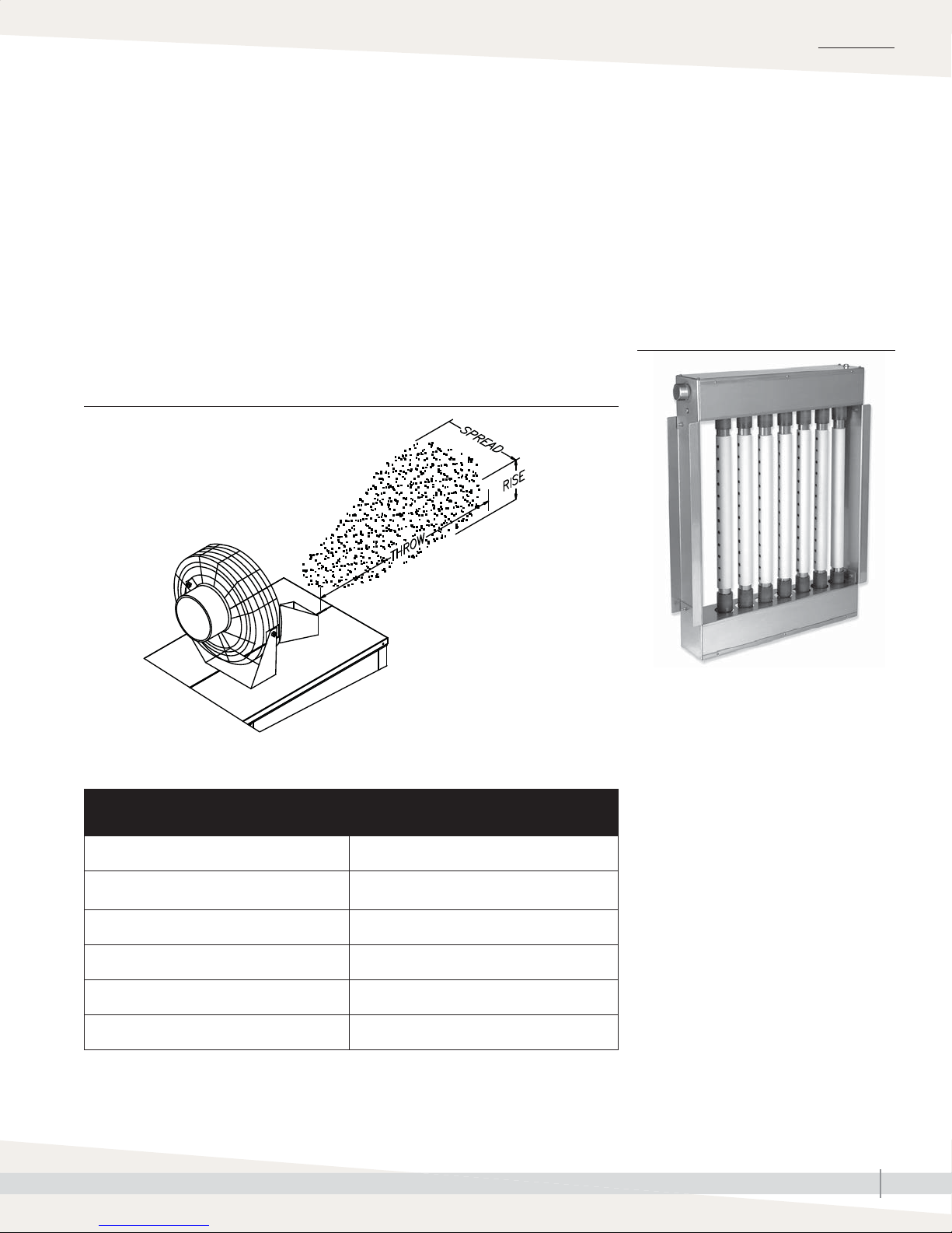
INSTALLATION
Dispersion:
Area-type fan
Table 48-1 lists the Area-type steam minimum rise, spread, and throw
nonwetting dimensions. Surfaces or objects located within this minimum
dimension can cause condensation and dripping.
The greater the space relative humidity, the higher and farther the discharged
steam will carry and rise in the space until becoming absorbed.
The Area-type fan, brackets, and wiring are factory installed on the humidifi er.
Note: For European Area-type models, contact your Distributor for parts.
FIGURE 49-2: AREA-TYPE RISE, SPREAD, THROW
ULTRA-SORB
Ultra-sorb
For Ultra-sorb steam dispersion panel
instructions, see the installation, operation,
and maintenance manual shipped with the
Ultra-sorb.
Also see Figure 49-1.
FIGURE 49-1: ULTRA-SORB WITH THE
HIGH-EFFICIENCY TUBE OPTION
OM-1230
Table 49-1:
Area-type electric fan specifications
Motor 120 V, 50/60 Hz
Blade diameter 18" (457 mm)
Speeds 3
Control Rotary switch
RPM (high speed) 1500
Amps (high speed) 1.52
High-efficiency Tube option
Dispersion assemblies with the High-effi ciency
Tube option are designed to produce
signifi cantly less dispersion-generated
condensate and airstream heat gain, which
reduces wasted energy by up to 85%.
These improvements are accomplished by
reducing the thermal conductivity of the tubes
with 1/8" of polyvinylidene fl uoride (PVDF)
insulating material on the outside of the tubes.
These assemblies require careful unpacking,
installation, and handling.
GTS INSTALLATION, OPERATION, AND MAINTENANCE MANUAL
49
Page 56

OPERATION
Start-up
START-UP CHECKLIST
After the system is installed and connected to gas, electrical, water supplies,
and controls, check the following items:
☐ Verify that the GTS humidifi er, controls, piping, electrical connections, steam
supply, and dispersion unit(s) are installed according to the following:
• Installation instructions in this manual
• Vapor-logic Installation and Operation Manual (shipped with the
humidifi er)
– Installation section
– Installation checklist
• Ladder style wiring diagram (shipped inside unit)
• External connections wiring diagram (shipped inside unit)
• Gas connection instructions in this manual
• Mounting instructions in this manual
• All governing codes
☐ Piping (gas)
• Verify that the gas type supplied to the humidifi er matches the unit
nameplate label.
• Verify that all fi eld and humidifi er gas piping has been tested for leaks.
(Soap and water are not recommended near gas valves.)
☐ Piping (steam, drain, supply water)—Verify that all piping connections have
been completed as recommended and that water pressure is available.
WARNING
Startup
Only qualifi ed electrical and gas
personnel should perform the start-up
procedure.
The Vapor-logic Installation and Operation
Manual is a comprehensive operation manual.
Refer to it for information regarding the
following features:
• Keypad display setup and menu information
• Control input signals and functions
• Drain, fl ush, and skim features
• Safety features
• Alarm screens and fault messages
The manual was shipped with your humidifi er.
Additional copies can be viewed, printed, or
ordered on our website: www.dristeem.com
☐ Electrical—Verify that all wiring connections have been made in accordance
with all governing codes and the GTS wiring diagrams.
☐ Controls—Verify that all control wiring has been completed as specifi ed and
required for correct and safe operation of the GTS humidifi er. Refer to the
Vapor-logic Installation and Operation Manual.
☐ Verify that the humidifi er tank is securely installed and level before fi lling
with water (see the operating weights in Table 4-1.
☐ Verify that the humidifi er tank is level front to back and side to side after it is
full of water.
GTS INSTALLATION, OPERATION, AND MAINTENANCE MANUAL
50
Page 57

Start-up
OPERATION
START-UP PROCEDURE
1. Refer to the Vapor-logic Installation and Operation Manual, and verify that
the installer has followed the Pre-installation Checklist (including proper
wiring).
2. Follow the “Start-up commissioning checklist” on Pages 52 and 53 of this
manual.
Note: During start-up, do not leave the humidifi er unattended.
3. Monitor the humidifier operation through multiple fill cycles. The humidifier
operating status appears on the Vapor-logic keypad/display.
Notes:
• On tap/softened water units, water skims from the humidifi er after every
fi ll cycle. Adjust the amount of skim by increasing or decreasing the skim
time (see the Vapor-logic Installation and Operation Manual).
• At start-up, DriSteem recommends initially running the humidifi er with the
factory default setting for skim time. See “Adjusting skim duration” on
Page 56, and see the Vapor-logic controller Setup menu.
For complete operating instructions, read and follow the instructions in the
“Operation” section of the Vapor-logic Installation and Operation Manual.
Systems and safeguards
The GTS humidifi er has a number of systems
and safeguards to ensure proper operation.
• When there is a call for humidity, all of
the combustion blowers must start. Each
combustion blower sends a signal to the
microprocessor relaying its current speed. If
this actual speed is outside an acceptable
range, the GTS will not operate.
• The negative pressure gas valves used on the
GTS are designed to keep a constant ratio of
air and gas throughout the operating range
of the blower. If the fl ue becomes blocked
or the blower fails to run, the blocked fl ue
sensor will shut down the humidifi er.
• During operation, the water level in the tank
is monitored by a probe system for tap/
softened water units and by a low water
fl oat for RO/DI units. These water monitors
tie into the Vapor-logic controller. If the water
level drops below a safe point, the controller
turns heaters off and tries to fi ll. If humidifi er
is unable to fi ll within a defi ned time period,
an “Excessive refi ll time” alarm appears in
the Vapor-logic Alarm Log. The heaters will
remain off until this alarm is cleared. (For
more about alarms, see the Vapor-logic
Installation and Operation Manual.)
• In tap/softened water applications, the
water level in the tank is also monitored
by a redundant low-water system that runs
independently of the Vapor-logic. This system
is tied directly into the power source for
the gas valves. If this system detects a low
water condition, the humidifi er shuts down
until water is present or until the a “GTS low
water” alarm is cleared from the Vapor-logic
Alarm Log.
• In addition to monitoring the water level,
there is a temperature sensor located near
the top of the heat exchanger. If the water
level drops too low and both the main and
redundant low water sensors fail to detect
it, the temperature sensor shuts down the
humidifi er before an unsafe condition occurs.
GTS INSTALLATION, OPERATION, AND MAINTENANCE MANUAL
51
Page 58

OPERATION
Start-up commissioning checklist
Visit date _______________________________________________
Model # ________________________________________________
Serial # _________________________________________________
Tag # ___________________________________________________
Important: Troubleshooting information for this humidifi er is
located in the Vapor-logic Installation and Operation Manual shipped
with your humidifi er. If you do not have this manual, go to www.
dristeem.com to download or order a copy.
Supply water
☐ RO
☐ DI
☐ Softened
☐ Potable
Grains hardness ______________________________________
☐ Hot*
☐ Cold
Water pressure ________________ psi
(must be between 25 and 80 psi
[172 and 582 kPa])
☐ Supply water piping is 3/8" pipe thread (DN10) minimum
Float adjustments (DI system)
____________________________________________________
* If using heated supply water, disconnect the supply water
line to the water tempering device at the fi ll manifold and
reconnect it to a cold water supply. This will ensure that the
water tempering device operates properly.
Gas supply
☐ Natural
☐ LP
Manifold pressure _____ inches wc ( _____ kPa)
Supply shutoff valve distance ___________________________
Supply line size _______________________________________
Flue piping
Class ________________________________________________
Size _________________________________________________
Rise _________________________________________________
Run _________________________________________________
☐ Slight pitch toward drip tee
☐ Termination point capped and covered
Power venter location __________________________________
Barometric damper location ____________________________
Job site representation:
________________________________________________________
________________________________________________________
________________________________________________________
Job name _______________________________________________
Program code ___________________________________________
DriSteem rep ____________________________________________
Required clearances
☐ Top cover removal 18" (457 mm)
☐ Distance vent box to combustible 30" (762 mm)
☐ Cleanout plate side 36" (914 mm)
Wiring
☐ Control transmitter
Gauge _________
☐ Shield
☐ High limit duct humidistat
Gauge _________
☐ Shield
☐ Airfl ow proving switch
☐ Power vent
☐ Combustion air damper
☐ Area-type fan
☐ External fault contact
☐ Twisted pair connection between boards
(for multiple units only)
Steam pipe
Outlet size ___________________________________________
☐ Flange
☐ Hard pipe
☐ Insulated
☐ Steam hose (do not insulate)
Rise _________________________________________________
Run _________________________________________________
☐ Pitched back to humidifi er
☐ 45° angles used in piping
Continued
GTS INSTALLATION, OPERATION, AND MAINTENANCE MANUAL
52
Page 59

Start-up commissioning checklist
OPERATION
Dispersion
☐ Ultra-sorb
☐ Rapid-sorb
☐ Single tube
☐ Single tube with drain
☐ Area-type fan
Condensate/drain piping
Water seal height of dispersion system
____________________________________________________
☐ Air gap
☐ Condensate return to tank
☐ Drane-kooler
Cold-start burner ignition
Burner 1 lights after: ☐ First try
☐ Second try
☐ Third try
Burner 1 color after 15 minutes:
☐ Blue
☐ Orange
☐ Red-orange
Burner 2 lights after: ☐ First try
☐ Second try
☐ Third try
Burner 2 color after 15 minutes:
☐ Blue
☐ Orange
☐ Red-orange
Burner 3 lights after: ☐ First try
☐ Second try
☐ Third try
Burner 3 color after 15 minutes:
☐ Blue
☐ Orange
☐ Red-orange
Burner 4 lights after: ☐ First try
☐ Second try
☐ Third try
Burner 4 color after 15 minutes:
☐ Blue
☐ Orange
☐ Red-orange
Safety testing to verify function
Low water test ________________________________________
High humidity limit test _________________________________
Airfl ow test ___________________________________________
Aquastat test _________________________________________
Additional comments
__________________________________________________
__________________________________________________
__________________________________________________
__________________________________________________
__________________________________________________
__________________________________________________
__________________________________________________
__________________________________________________
__________________________________________________
__________________________________________________
__________________________________________________
__________________________________________________
__________________________________________________
__________________________________________________
__________________________________________________
__________________________________________________
__________________________________________________
__________________________________________________
__________________________________________________
__________________________________________________
__________________________________________________
__________________________________________________
__________________________________________________
__________________________________________________
GTS INSTALLATION, OPERATION, AND MAINTENANCE MANUAL
53
Page 60
MAINTENANCE
Inspection recommendations
USER INSPECTION EVERY 30 DAYS
• Vent connector is in place, sloping upward and is physically sound without
holes or excessive corrosion.
• Physical support of the appliance is sound without sagging, cracks, or
gaps between fl oor stand or tank fl anges.
• There are no obvious signs of deterioration of the appliance.
• Burner fl ame is primarily orange in color — up to a 1/4" (6 mm) from the
surface of the burner.
• Check for alarms and messages through the message/alarm log.
See Vapor-logic controller instruction manual for description and
troubleshooting.
• Check ignition sequence:
1. Ignitor energized - visual orange glow noted at the burner sight glass
2. Gas valve on (click) 2-3 seconds after ignitor glows
3. Flame on the burner
4. Flame rectifi cation - fl ame is sensed
5. Burner stays on - visual inferred glow (brilliant orange)
• Replace ignitor at regular intervals
1. When cycle count exceeds 80,000
• Notifi cation will appear on Vapor-logic controller
• First alarm at 80,000 cycles
• Second alarm and shut-off at 100,000 cycles
• Replacement verifi cation required to re-start cycle count
2. If signs of cracking or uneven heating are noted during ignition sequence
check, or if unit fails to ignite after three attempts.
Note: If replacing the ignition ignitor, reset the GTS ignitor counter through
the Vapor-logic controller setup screen. See the Vapor-logic Installation and
Operation Manual for instructions.
WARNING
Shutdown procedure
To prevent severe personal injury
or death from electrical shock, fi re,
or explosion, follow this shutdown
procedure before performing service
or maintenance procedures on this
humidifi er.
1. Use Vapor-logic keypad/display,
change the control mode to
Standby.
2. Place all power disconnects in OFF
position and lock in OFF position.
3. Close fi eld-installed manual supply
water shut-off valve.
4. Close gas shut-off valves.
Table 54-1:
GTS products of combustion
guidelines (at 100% demand)
CO
CO2%
O2% 4 – 7 %
Flue
temperature
Less than 40 ppm; 0 or low
single digits is typical
8-10%; 9% is typical for natural
gas, 10% is typical for LP gas
Less than 400°F plus room
temperature
(Less than 204.4°C plus room
temperature)
GTS INSTALLATION, OPERATION, AND MAINTENANCE MANUAL
54
Burner
effi ciency
Troubleshooting
The Vapor-logic Installation and Operation
Manual that shipped with your humidifi er is a
comprehensive operation manual. Refer to it for
troubleshooting information.
Greater than 80%
Page 61

Inspection recommendations
APPLIANCE SYSTEM INSPECTED AT A MINIMUM ONCE A YEAR BY A QUALIFIED
SERVICE PERSON (ANNUAL PRE-SEASONAL INSPECTION)
• Proper fi eld operation of burner. Measure CO, CO2%, O2%, fl ue
temperature, and burner effi ciency at 100% demand with the tank at a boil.
Verify that measurements are within the guidelines described in Table 55-1;
if not, consult DriSteem.
• Flue passageways external to the appliance, such as vent connector and
chimney, are clear and free of obstructions.
• Upgrade Vapor-logic software to the latest version.
• At least annually, inspect the ventilation apparatus, ensuring the following:
– Vent connector is in place, sloping upward, and physically sound
without holes or excessive corrosion.
– Physical support of the appliance is sound without sagging, cracks, or
gaps between fl oor stand or tank fl anges.
– Adequate combustion and ventilation air in accordance with Section
5.3, Air for Combustion and Ventilation, of the National Fuel Gas Code,
ANSI Z223.1 or applicable provisions of governing codes.
Canadian installations must be installed in accordance with sections
7.2, 7.3, and 7.4 of the CAN/CGA.B149 Installation Codes and all
authorities having jurisdiction.
MAINTENANCE
REPLACEMENT PARTS
When servicing or repairing this equipment, use only DriSteem-approved
service replacement parts. Complete replacement part lists are on Pages 62
through 69. Refer to the rating plate on the GTS humidifi er for complete unit
model number, serial number, and company address. Any substitution of parts
or controls not approved by DriSteem will be at owner’s risk and will void the
warranty.
GTS INSTALLATION, OPERATION, AND MAINTENANCE MANUAL
55
Page 62

MAINTENANCE
Burners
BURNER ASSEMBLIES AND HEAT EXCHANGER TUBES
This is not a regular maintenance item, but if the heat exchanger tubes contain
carbon deposits, soot, or other residue, clean as follows:
1. Follow shutdown procedure on Page 54.
2. Remove gas train shroud.
3. Disconnect wiring to blowers, flame sensors, gas valves, and ignition
controllers. Remove burner assemblies (each assembly is mounted with four
bolts).
4. Remove vent box.
5. Use a 6" (150 mm) flue brush with a 24" (600 mm) extension and
reversible drill. Work brush in and out of all combustion chambers.
Note: To ease reassembly, disconnect components from one burner
assembly at a time, and clean each corresponding combustion
chamber individually.
WARNING
Respiratory hazard
When cleaning burners with
compressed air, wear appropriate
respiratory protection. Failure to do so
may cause severe bodily injury.
Note:
Soot and carbon deposits may indicate a
combustion problem that needs to be corrected.
Consult the factory.
6. Remove loose deposits and residue that falls into rear header with vacuum
cleaner and hose extension.
7. Inspect 1½" (DN40) return tubes. Clean if necessary.
8. Run thin brush between turbulator and tube wall on all four sides.
9. Reinstall burner assemblies and gaskets, vent box and gasket, all electrical
wiring, gas train shroud, and pressure switch connections.
MAINTENANCE FREQUENCY
Under normal use conditions, the burner(s) should not need cleaning for a
minimum of fi ve years. However, depending on the operating environment,
the burner(s) may require periodic cleaning to remove accumulated materials.
Failure to clean burners can result in reduced unit capacity. Use sealed
combustion in dirty environments. See burner maintenance instructions below.
BURNER MAINTENANCE INSTRUCTIONS
To service the burner system, clean both the blower and the burner. Remove the
blower(s) from the system and clean dust from the wheel. Remove the burner(s)
for cleaning. Removing and cleaning one burner at a time eases reassembly.
To dislodge particulate matter from the burner surface matrix, use compressed
air (100 psig [700 kPa] maximum). Keep the air nozzle about 2" (50 mm)
from the burner’s surface, blowing air perpendicular to the burner surface
while moving the nozzle back and forth lengthwise. This dislodges particles
trapped in the matrix, pushing them back inside the burner. Avoid blowing
air across the surface, which tends to have a destructive effect on the burner
surface. Allow particulate matter to fall from the burner through the air/gas
inlet. To assist in removing the particulate matter, use a vacuum at the burner’s
air/gas inlet.
GTS INSTALLATION, OPERATION, AND MAINTENANCE MANUAL
56
Page 63

Tap/softened water
MAINTENANCE
WATER QUALITY RECOMMENDATIONS
The best way to determine how often your particular system needs
maintenance is to remove the probe plate and inspect it for mineral deposits
after three months of duty. Potable water carries a variety of minerals and other
materials in a mix that varies from location to location. This variation in water
quality, combined with the hours of operation and duty cycle, will determine
your own unique maintenance schedule.
WATER QUALITY MAKES A DIFFERENCE
• Light to moderately hard water (2 to 10 grains hardness per gallon
[35 mg/L to 170 mg/L]) requires:
– Annual cleaning
– Regular skimming
• High mineral content water (more than 10 grains hardness per gallon
[more than 170 mg/L]) requires:
– Cleaning frequency determined by use and water quality
– Regular skimming
– Periodic drain and fl ush cycles
• Softened water dramatically reduces mineral accumulation inside tap/
softened water models.
Humidifier De-scaling solution
Scale buildup on humidifi er heat exchangers
acts as an insulator, reducing humidifi er
performance while increasing energy costs.
To keep humidifi ers operating as effi ciently
as possible, remove scale with DriSteem's
Humidifi er De-scaling Solution, available for
purchase from your DriSteem representative or
distributor.
The De-scaling Solution cleans without risk
of corroding humidifi er tanks or welds. The
De-scaling Solution also cleans surfaces
unreachable by hand scraping.
DriSteem's Humidifi er De-scaling Solution is the
only approved cleaner/de-scaler for use with
DriSteem humidifi ers. Use of other cleaners/
de-scalers may void your DriSteem warranty.
mc_021908_1405
Note: Solids, like silica, are not removed in the softening process.
ADJUSTING SKIM DURATION
The skim time duration determines the quantity of water skimmed with each fi ll
cycle. Skim time is fi eld adjustable using the Vapor-logic keypad.
Each time the GTS refi lls, it fi lls to an elevation near the lip of the skim/
overfl ow fi tting. A portion of the refi ll water then fl ows to the drain carrying
most of the minerals left by the previous evaporating cycle. This reduces the
mineral concentration, thereby reducing the frequency of cleaning needed.
The heated water that fl ows to the drain is an operational cost. Cleaning the
humidifi er also is an operational cost. Therefore, DriSteem recommends that the
user observe and adjust the skimming quantity to achieve a balance between
minimizing mineral buildup and conserving heated water.
GTS INSTALLATION, OPERATION, AND MAINTENANCE MANUAL
57
Page 64

MAINTENANCE
Tap/softened water
COOL DOWN PROCEDURE
Before performing any maintenance, allow the tank to cool down.
• Insulated and uninsulated tanks will have hot surfaces.
• Verify that there is no call for humidity and that the aquastat set point
(adjusted using the keypad/display Set Up screens) is less than room
temperature (default setting is 40 °F [4 °C]) so the burners do not energize
while cooling down the tank.
• Models with a standard drain valve:
1. Manually open the drain valve by moving the valve lever located on the
back of the drain valve to the manual open position.
2. The fi ll valve eventually opens.
3. Let the fi ll water run until the tank is cooled; then shut off the fi eld-
installed manual supply water shut-off valve.
4. Let the tank drain; then manually close the drain valve.
• For models without a manually operated drain valve, use the keypad to
perform the cool down process.
1. From the Main menu, enter the Tank Status submenu.
2. Change mode to Drain, and allow approximately half the water to drain
out of the tank.
3. Change the mode back to Auto; the fi ll valve opens and the humidifi er
cools down.
4. When the fi ll valve closes, go back into Drain mode, and allow the tank
to drain completely. The humidifi er should be cool enough to work on.
Note: For more information about using the keypad, see the
Vapor-logic Installation and Operation Manual.
GTS INSTALLATION, OPERATION, AND MAINTENANCE MANUAL
58
Page 65

Tap/softened water
INSPECTION AND MAINTENANCE
1. Annually (also recommended when maintenance is performed)
• Inspect tank, piping, and gaskets for water and gas leaks.
• All safety devices in the control circuit should be cycled on and off to
verify they are functioning. These include:
– High limit switch
– Airfl ow proving switch
– Low water level probe. Pull out probe plug; fi ll valve should energize.
– Redundant low water level probe
2. Seasonally (or as required, depending on water quality)
• Clean tank
– Remove cleanout plate and dispose of any loose scale that has
collected in the tank. Do this before the scale buildup reaches the
bottom of the heat exchanger.
– Inspect the area inside the tank in front of the drain valve fi tting and
thoroughly clean all scale and mineral buildup from that area.
• Dismantle and clean drain valve and associated piping
• Clean the probes
– Access the probe assembly either from the electrical panel or by
removing the roof panel above the electrical area.
– Disconnect the probe plug and cable assembly and unscrew the
probe rod assembly from the humidifi er probe housing.
– Inspect the probe housing and clean, ensuring that all the housing
passageways are clear. Remove the housing from the tank by
removing the cover plate from the tank.
– The scale should fl ake off easily from the probe assembly rods.
– The bottom 3/8" (10 mm) of each rod is the sensing portion; clean
these areas with a wire brush, abrasive pad, or steel wool.
– Inspect the composite plastic probe rod assembly for any signs
of cracking, roughness, or deterioration. If found, replace probe
assembly.
– Reassemble the probe assembly.
MAINTENANCE
WARNING
Follow the shutdown procedure
Follow the shutdown procedure on
Page 54 before performing service
or maintenance procedures on this
humidifi er. Failure to follow the
shutdown procedure could cause
electrical shock, fi re, or explosion and
severe personal injury or death.
GTS INSTALLATION, OPERATION, AND MAINTENANCE MANUAL
59
Page 66

MAINTENANCE
Tap/softened water
• Clean the skim/overfl ow port
– Water should drain from the skimmer drain pipe after each fi ll cycle.
This should be verifi ed visually by a weekly inspection.
– Loosen deposits in and around the skimmer/overfl ow port with a
long tool such as a screwdriver.
– If fl ow through the water seal/P-trap is diminished due to mineral
accumulation:
- Remove the water seal piping from the humidifi er and fl ush out.
- Replace the water seal with new piping if the minerals have
hardened in the water seal.
• Clean the low water cutout probe — Remove the shroud cover and
inspect the probe rod for mineral accumulation. The rod is located on
the top of the tank near the back. Use stainless steel wool to clean the
probe.
• Inspect blower motor — A lubrication port is not provided, therefore
lubrication is not required.
• Remove dust — Using a vacuum, remove all dust from areas around the
motor, vent fan(s), and louvers that allow air to the shrouded area.
• When the maintenance requirements are complete:
– Replace cleanout plate and tighten the nuts on the plate. Torque the
nuts to 25 to 35 in-lb (2.8 to 4.0 N-m).
– Verify that the probe rod holder is secure and that the probe plug
and cable assembly are plugged into the probe rod holder.
– Verify that the drain valve assembly is in the closed position.
– Replace and secure all covers and doors.
– Turn on the water supply.
– Turn on the electrical power.
– Turn on gas.
– Do not leave humidifi er unattended. Allow the humidifi er to cycle
through multiple fi ll cycles and verify that the humidifi er cover,
cleanout plate, and probe holder gasket are not leaking.
Important:
Minimum supply water pressure is 25 psi
(172 kPa).
3. Off-season maintenance
• Perform complete inspection and cleaning of the following:
– Probe rods
– Skimmer port and water seal
– Humidifi er tank
– Heat exchanger
• After cleaning, the humidifi er should remain empty until humidifi cation is
required.
GTS INSTALLATION, OPERATION, AND MAINTENANCE MANUAL
60
Page 67

RO/DI water option
RO/DI WATER QUALITY RECOMMENDATIONS
• Verify regularly that water processing equipment is operating correctly. The
presence of chlorides in improperly processed DI water can cause pitting
and failure of the tank and heat exchanger. Your DriSteem warranty does
not cover damage caused by chloride corrosion.
• GTS humidifi ers with the RO/DI water option do not require regular
cleaning, although regular inspections are advised.
• GTS humidifi ers with the RO/DI water option do not require skimming or
draining and fl ushing to remove precipitated minerals. However, at the
end of a humidifi cation season, drain all DI humidifi ers either by manually
opening the drain valve or by programming the humidifi er to automatically
drain at end-of-season (electric fi ll and drain valve required).
MAINTENANCE
WARNING
Follow the shutdown procedure
Follow the shutdown procedure on
Page 54 before performing service
or maintenance procedures on this
humidifi er. Failure to follow the
shutdown procedure could cause
electrical shock, fi re, or explosion and
severe personal injury or death.
GTS INSTALLATION, OPERATION, AND MAINTENANCE MANUAL
61
Page 68

MAINTENANCE
RO/DI water option
COOL DOWN PROCEDURE
Before performing any maintenance, allow the tank to cool down.
Note: Fresh make-up water is used to speed up cooling. Do not close the
manual water supply before cooling down the humidifi er; otherwise the
tank could stay hot for several hours.
• Tanks will have hot surfaces.
• Verify that there is no call for humidity and that the aquastat set point
(adjusted using the keypad/display Set Up screens) is less than room
temperature (default setting is 40 °F [4 °C]) so the burners do not energize
while cooling down the tank.
• Models with a standard drain valve:
– Manually open the drain valve.
– The fl oat valve opens.
– Let the fi ll water run until the tank is cooled; then shut off the fi eld-
installed manual supply water shut-off valve.
– Let the tank drain; then manually close the drain valve.
• For models without a manually operated drain valve, use the keypad to
perform the cool down process.
– From the Main menu, enter the Tank Status submenu.
– Change mode to Drain, and allow approximately half the water to drain
out of the tank.
– Change the mode back to Auto; the fi ll valve opens and the humidifi er
cools down.
– When the fi ll valve closes, go back into Drain mode, and allow the tank
to drain completely. The humidifi er should be cool enough to work on.
– For more information about using the keypad, see the
Vapor-logic Installation and Operation Manual.
GTS INSTALLATION, OPERATION, AND MAINTENANCE MANUAL
62
Page 69

RO/DI water option
INSPECTION
1. Annually (also recommended when maintenance is performed)
• All safety devices in the control circuit should be cycled on and off to
verify they are functioning. These include:
– High limit switch
– Airfl ow proving switch
– Low water cutoff switch
– Redundant low water cutoff switch
• Inspect tank and gaskets for leaks.
• Verify that the fl oat valve is closing off. If the fl oat valve will not shut off,
there may be particulate on the valve seat, or the EPDM seat may be
worn and in need of replacement.
• As long as mineral-free water is used in the GTS, no cleaning or fl ushing
of the humidifi er should be necessary.
MAINTENANCE
WARNING
Prevent wiring errors
When servicing controls, before
disconnecting, label all areas. Wiring
errors can cause explosion or fi re,
resulting in severe bodily injury, death,
or signifi cant property damage.
2. Seasonally (or as required, depending on water quality)
• Inspect blower motor. Since a lubrication port is not provided,
lubrication is not required.
• Remove dust — Using a vacuum, remove all dust from areas around the
motor, vent fan(s), and louvers that allow air to the shaded area.
3. Off-season maintenance
• Perform a complete inspection of the following:
– Float valve
– Low water cutoff switch
– Redundant low water cutoff switch
– Humidifi er tank and gaskets
– Heat exchanger
• Drain humidifi er tank and rinse.
• After inspection, the humidifi er should remain empty until humidifi cation
is required.
GTS INSTALLATION, OPERATION, AND MAINTENANCE MANUAL
63
Page 70
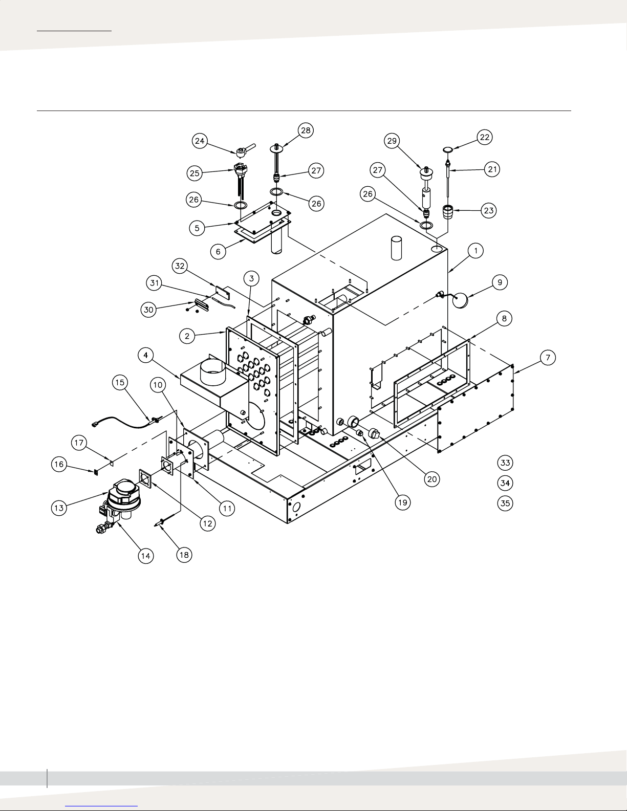
REPLACEMENT PARTS
GTS humidifi er
FIGURE 64-1: GTS REPLACEMENT PARTS
OM-1243
GTS INSTALLATION, OPERATION, AND MAINTENANCE MANUAL
64
Page 71
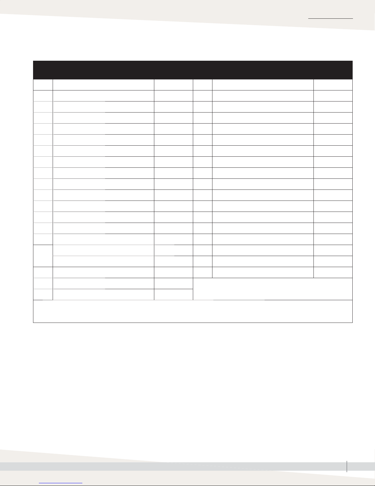
REPLACEMENT PARTS
GTS humidifi er
Table 65-1:
GTS replacement parts
No. Description Part no. No. Description Part no.
1 Tank Consult factory 19 Plug, 3/4" 250192-002
2 Heat exchanger Consult factory 20 Plug, 1½" 250681-002
3 Heat exchanger gasket Consult factory 21 Redundant probe * 405726-001
4 Flue box Consult factory 22 Bushing 405805-004
5 Probe plate 165302-005 23 Adapter weld * 168010-005
6 Probe plate gasket 308235-006 24 Probe plug * 406050-100
7 Cleanout plate 165479-001 25 Probe assembly * 406303-010
8 Cleanout plate gasket 308235-005 26 Probe gasket 309750-004
9 DI fl oat valve assembly ** Consult factory 27 DI fl oat switch ** 408420-002
10 Burner gasket 308230-006 28 DI fl oat weld ** 167789
11 Burner Consult factory 29 Redundant DI fl oat weld ** 167789-002
12 Blower gasket 308230-007 30 Temperature sensor bracket 128666-001
13 Blower 405800-003 31 Temperature sensor 405760
14 Gas valve 405800-007 32 Temperature sensor gasket 308230-011
Ignitor, 120 V US/Canada 405718 33 Gas manifold weld *** Consult factory
15
Ignitor, 230 V Europe 405718-001 34 Sealed combustion assembly *** Consult factory
16 Sight glass bracket 128661 35 Pallet/shroud components *** Consult factory
17 Sight glass 405720
18 Flame sensor 405725
* Tap/softened water GTS only
** GTS with RO/DI water option only
*** Not shown
GTS INSTALLATION, OPERATION, AND MAINTENANCE MANUAL
65
Page 72
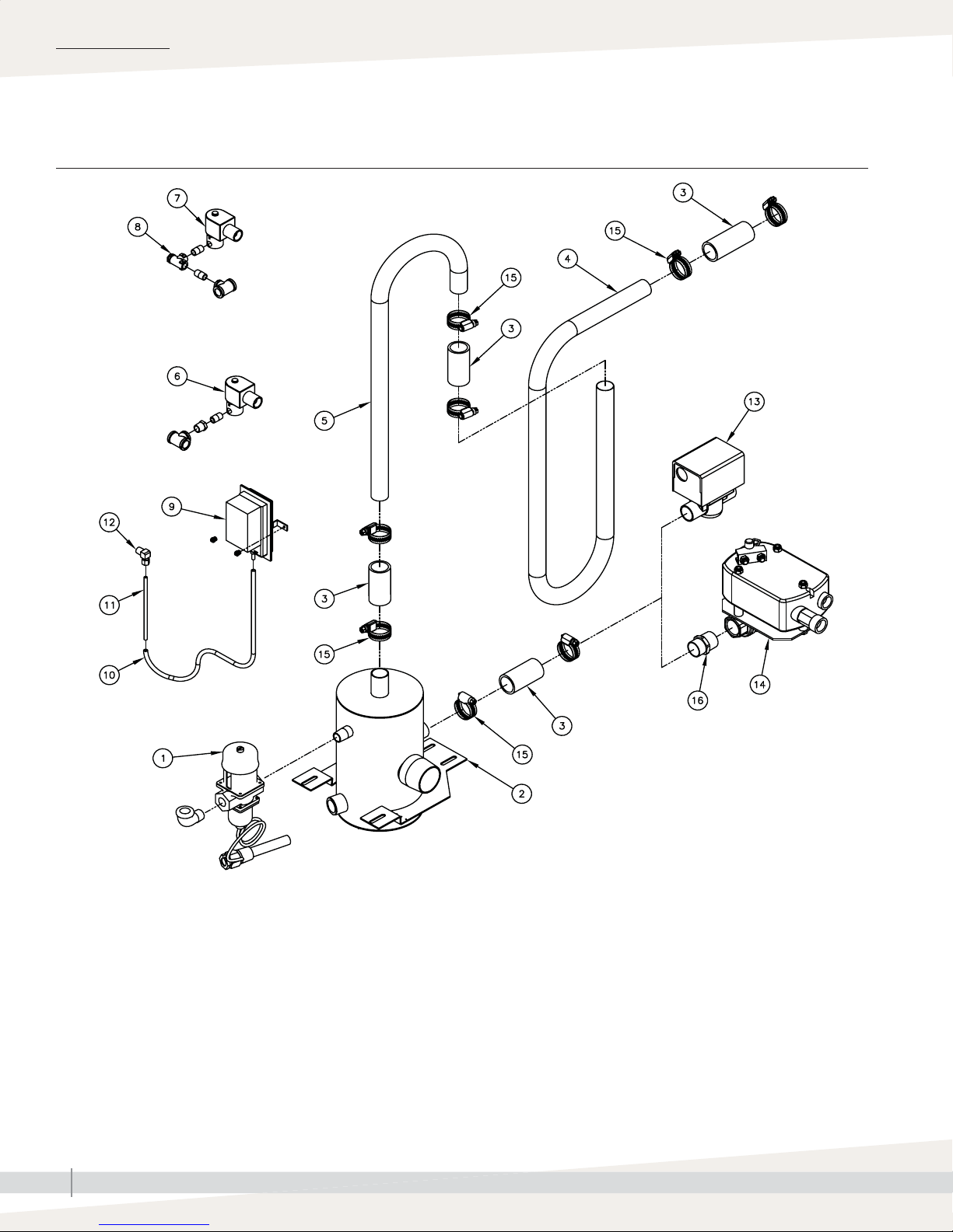
REPLACEMENT PARTS
Fill, drain, and blocked fl ue sensor
FIGURE 66-1: GTS FILL, DRAIN, AND BLOCKED FLUE REPLACEMENT PARTS
OM-1244
GTS INSTALLATION, OPERATION, AND MAINTENANCE MANUAL
66
Page 73

Fill, drain, and blocked fl ue sensor
Table 67-1:
GTS fill, drain, and blocked flue sensor replacement parts
No. Description Part no.
1 Water tempering valve 505090
2 Water tempering tank Consult factory
3 Drain hose cuff 305389-003
4 Top water seal tube 204812-201
5 Bottom water seal tube 204812-202
6 Fill valve, DI EOS models ** 505086
7 Fill valve, tap/softened water models * 505095
8 Strainer * 300050
9 Blocked fl ue sensor 406190
REPLACEMENT PARTS
10 Flexible tubing 405722
11 Copper tubing 100038-025
12 Compression elbow 405723
13 Drain valve, tap/softened water models * 505075
14 Drain valve, DI-EOS models ** 193458
15 Hose clamp 700560-100
16 Adapter, NPT × C 204700
17 Fill hose *** Consult factory
18 Water tempering hose *** Consult factory
* Tap/softened water GTS only
** GTS with RO/DI water option only
*** Not shown
GTS INSTALLATION, OPERATION, AND MAINTENANCE MANUAL
67
Page 74
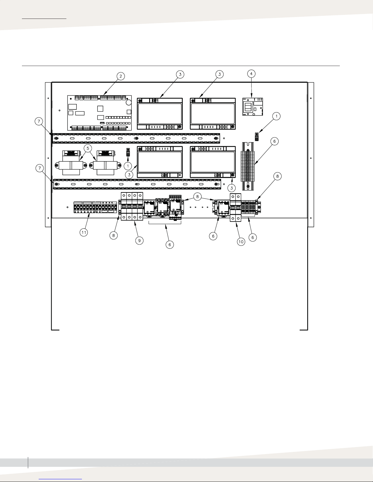
REPLACEMENT PARTS
Electrical parts
FIGURE 68-1: GTS ELECTRICAL REPLACEMENT PARTS
Note: See Pages 68 and 69 for GTS Outdoor Enclosure replacement parts.
OM-7470
GTS INSTALLATION, OPERATION, AND MAINTENANCE MANUAL
68
Page 75

Electrical parts
Table 69-1:
GTS electrical replacement parts
No. Description Part no.
1 Ground wire lug 409250-003
2 Vapor-logic main board 183504-014
Ignition module (for North America) 405800-006
3
Ignition module (for Europe) 405800-005
4 Low water board * 405726 *
Transformer (for North America) 408965-001
5
Transformer (for Europe) 408985
6 Relays, Sockets, time delay Consult factory
7 Wire channel 408999-001
REPLACEMENT PARTS
8 DIN-rail end bracket 408252-006
9 Circuit breaker, 2-pole (for Europe only) 406775-004
10 Circuit breaker, single-pole (for SDU option only) 406775-009
11 Terminal strip Consult factory
* Tap/softened water GTS only
GTS INSTALLATION, OPERATION, AND MAINTENANCE MANUAL
69
Page 76
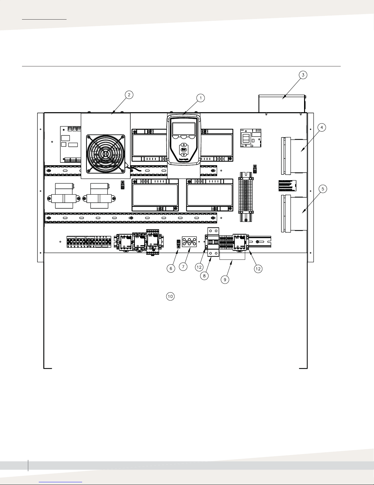
REPLACEMENT PARTS
Outdoor Enclosure
FIGURE 70-1: OUTDOOR ENCLOSURE ELECTRICAL REPLACEMENT PARTS
Note: For European models, refer to Fisair diagrams
OM-7471
Not shown
GTS INSTALLATION, OPERATION, AND MAINTENANCE MANUAL
70
Page 77

Outdoor Enclosure
Table 71-1:
Outdoor Enclosure electrical replacement parts
No. Description Part no.
1 Vapor-logic display with back
Fan assembly (for North America) 185110-003
2
Fan assembly (for Europe) 185110-004
3 High limit stat 405800-065
Fan stat (for North America) 405800-067
4
Fan stat (for Europe) 405871-002
Heater stat (for North America) 405800-066
5
Heater stat (for Europe) 405871-001
6 Ground wire lug 409250-003
REPLACEMENT PARTS
7 Power block 408300-002
8 Circuit breaker 406775-005
9 Relays, sockets, time delay Consult factory
10 Heater assembly, 600W * 183502-044
12 DIN-rail end bracket 408252-006
* Not shown
GTS INSTALLATION, OPERATION, AND MAINTENANCE MANUAL
71
Page 78
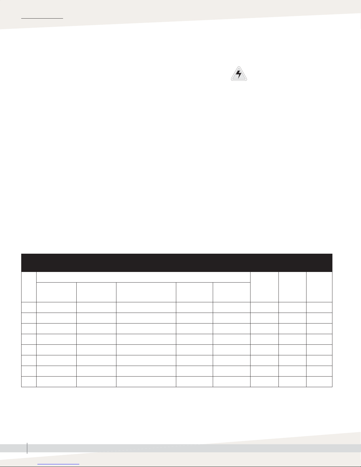
EUROPEAN MODELS
European models only
This equipment has been tested by the Canadian Standards Association
International to the Low Voltage, Gas Appliance, and EMC directives and has
been certifi ed by AFNOR for use in all EU countries.
AUTHORIZED COUNTRIES OF DESTINATION
GTS humidifi ers bearing the CE mark are authorized for use in the European
countries listed below.
Austria AT Greece GR
Belgium BE Ireland IE
Switzerland CH Iceland IS
Germany DE Italy IT
Denmark DK Luxembourg LU
Spain ES Netherlands NL
Finland FI Norway NO
France FR Portugal PT
United Kingdom GB Sweden SE
APPLIANCE CATEGORY
In relation to the country of destination, this humidifi er is classifi ed under one of
the following boiler categories: category I2H, I2L, I2E, I
2E+
, I
, I
, I
, I
, I
2LL
2ES
2Fi
2ER
3B/P
, I
3P
Electrical warning label
Location: Control cover, shroud
Defi nition: Electrical shock hazard
Important:
This equipment is for use with second family
(G20, G25) natural gases; and third family
(G30, G31) propane gas. Contact your
distributor before converting to another group
or supply pressure.
See the unit data plate for the specifi c category of your appliance.
Table 72-1:
Gas specifications for European models
Volumetric fl ow rate by gas category
GTS
2H-G20-20 mbar
model
2E-G20-20 mbar
2Es-G20-20 mbar
100 2.31 m
200 4.62 m3/h 5.64 m3/h 4.62-5.64 m3/h 2.62 m3/h 2.98 m3/h 163 °C -0.025 mbar 13.8 g/s
300 6.93 m3/h 8.46 m3/h 6.92-8.46 m3/h 3.93 m3/h 4.47 m3/h 191 °C -0.025 mbar 20.7 g/s
400 9.24 m3/h 11.28 m3/h 9.24-11.28 m3/h 5.24 m3/h 5.96 m3/h 218 °C -0.025 mbar 27.6 g/s
500 11.55 m3/h 14.10 m3/h 11.55-14.10 m3/h 6.55 m3/h 7.45 m3/h 218 °C -0.025 mbar 34.5 g/s
600 13.86 m3/h 16.92 m3/h 13.85-16.92 m3/h 7.86 m3/h 8.94 m3/h 218 °C -0.025 mbar 41.4 g/s
700 16.17 m3/h 19.74 m3/h 16.17-19.74 m3/h 9.17 m3/h 10.43 m3/h 218 °C -0.025 mbar 48.3 g/s
800 18.48 m3/h 22.56 m3/h 18.47-22.56 m3/h 10.48 m3/h 11.92 m3/h 218 °C -0.025 mbar 55.2 g/s
3
2L-G25-25 mbar
2LL-G25-20 mbar
2Ei-G25-25 mbar
/h 2.82 m3/h 2.31-2.82 m3/h 1.31 m3/h 1.49 m3/h 121 °C -0.025 mbar 6.9 g/s
2E+G20/G25-20/25 mbar
2ER-G20/G25-20/25 mbar
3B-G30-30 mbar
3B-G30-50 mbar
3P-G31-30 mbar
3P-G31-37 mbar
3P-G31-50 mbar
Average fl ue
temperature
Minimum
draught
requirement
Mass fl ow
rate of
combustion
products
GTS INSTALLATION, OPERATION, AND MAINTENANCE MANUAL
72
Page 79

EUROPEAN MODELS
European models only
Table 73-1:
GTS models, capacities, electrical specifications, and weights, European models
GTS
model
GTS-100 34 0-24 0-29
GTS-200 68 0-48 0-59
GTS-300 102 0-72 0-88 DN80 (3") fl ange DN180 (7") 385 205 4.0
GTS-400 136 0-96 0-117 DN80 (3") fl ange DN180 (7") 385 205 4.0
GTS-500 170 0-120 0-147 DN100 (4") fl ange DN200 (8") 500 270 5.5
GTS-600 204 0-144 0-176 DN100 (4") fl ange DN200 (8") 500 270 5.5
GTS-700 238 0-168 0-205 DN100 (4") fl ange DN250 (10") 635 320 7.0
GTS-800 272 0-192 0-234 DN100 (4") fl ange DN250 (10") 635 320 7.0
* Maximum steam capacities listed may be as much as 10% lower than the given values due to local variations in the Wobbe index of G20 and
G25 gases.
Steam
capacity per
hour in kg*
P = (kW) Q = (kW) Steam outlet
DN50 (2") BSPT
or DN50 hose
DN50 (2") BSPT
or DN50 hose
Recommended fl ue
size (Class B)
DN125 (5") 320 170 2.8
DN125 (5") 320 170 2.8
Operating
weight in kg
Shipping weight
in kg
Full load
amps
CAPACITY NOTES
• At sea level, 402 kJ are required to raise the temperature of one kilogram
of water from 4 °C to 100 °C.
• An additional 2257 kJ are required to change the state of one kilogram of
100 °C water to vapor.
• Another factor to consider is condensation steam loss from piping. See
Table 33-2.
LP GAS
All models operate at rated kW input.
OPERATING CHARACTERISTICS
• Unit is capable of operating in ambient conditions of 5 °C to 40 °C.
• Unit is capable of operating in ambient conditions between 30% RH and
95% RH (noncondensing).
• NOx class 5
GAS SUPPLY PRESSURE
20 or 25 mbar for natural gas (depending on gas group), and 30, 37 or 50
mbar for propane gas (depending on gas group)
PMS (ALL UNITS)
7.0 bar
CAUTION
Install connection for gas pressure test
gauge
Gas pressure to the humidifi er controls
must never exceed 6 kPa (60 mbar),
or the gas valve will become damaged
and require replacement. Install a 1/8"
pipe thread (DN6) plugged tapping,
accessible for test gauge connection,
immediately upstream of the gas supply
connection to the appliance.
ELECTRIC SUPPLY
230V, 667W to 2415W (see data plate)
MAX INLET WATER TEMPERATURE
90 °C
GTS INSTALLATION, OPERATION, AND MAINTENANCE MANUAL
73
Page 80

W
ARRANTY
Expect quality from the industry leader
Since 1965, DriSteem has led the industry with
innovative methods for humidifying and cooling
air with precise control. Our focus on ease of
ownership is evident in the design of the GTS
humidifi er, which features cleanable, stainless
steel construction. DriSteem also leads the
industry with a Two-year Limited Warranty and
optional extended warranty.
For more information
www.dristeem.com
[email protected]
For the most recent product information
visit our website: www.dristeem.com
DRI-STEEM Corporation
a subsidiary of Research Products Corporation
DriSteem is an ISO 9001:2000 certifi ed company
U.S. Headquarters:
14949 Technology Drive
Eden Prairie, MN 55344
800-328-4447 or 952-949-2415
952-229-3200 (fax)
European offi ce:
Grote Hellekensstraat 54 b
B-3520 Zonhoven
Belgium
+3211823595
E-mail: [email protected]
Continuous product improvement is a policy of
DriSteem; therefore, product features and
specifi cations are subject to change without
notice.
DriSteem, Area-type, Drane-kooler, DriCalc,
Rapid-sorb, Ultra-sorb, and Vapor-logic are
registered trademarks of Research Products
Corporation and are fi led for trademark
registration in Canada and the European
community.
Two-year Limited Warranty
DRI-STEEM Corporation (“DriSteem”) warrants to the original user that its products will be free from
defects in materials and workmanship for a period of two (2) years after installation or twentyseven (27) months from the date DriSteem ships such product, whichever date is the earlier.
If any DriSteem product is found to be defective in material or workmanship during the applicable
warranty period, DriSteem’s entire liability, and the purchaser’s sole and exclusive remedy,
shall be the repair or replacement of the defective product, or the refund of the purchase price,
at DriSteem’s election. DriSteem shall not be liable for any costs or expenses, whether direct
or indirect, associated with the installation, removal or reinstallation of any defective product.
Excluded from the Limited Warranty are all consumable and wear and tear items such as cylinders,
membranes, fi lters, or media replacements. These items are subject to usual wear and tear during
usage.
DriSteem’s Limited Warranty shall not be effective or actionable unless there is compliance with
all installation and operating instructions furnished by DriSteem, or if the products have been
modifi ed or altered without the written consent of DriSteem, or if such products have been subject
to accident, misuse, mishandling, tampering, negligence or improper maintenance. Any warranty
claim must be submitted to DriSteem in writing within the stated warranty period. Defective parts
may be required to be returned to DriSteem.
DriSteem’s Limited Warranty is made in lieu of, and DriSteem disclaims all other warranties,
whether express or implied, including but not limited to any IMPLIED WARRANTY OF
MERCHANTABILITY, ANY IMPLIED WARRANTY OF FITNESS FOR A PARTICULAR PURPOSE, any
implied warranty arising out of a course of dealing or of performance, custom or usage of trade.
DriSteem SHALL NOT, UNDER ANY CIRCUMSTANCES BE LIABLE FOR ANY DIRECT, INDIRECT,
INCIDENTAL, SPECIAL OR CONSEQUENTIAL DAMAGES (INCLUDING, BUT NOT LIMITED
TO, LOSS OF PROFITS, REVENUE OR BUSINESS) OR DAMAGE OR INJURY TO PERSONS OR
PROPERTY IN ANY WAY RELATED TO THE MANUFACTURE OR THE USE OF ITS PRODUCTS. The
exclusion applies regardless of whether such damages are sought based on breach of warranty,
breach of contract, negligence, strict liability in tort, or any other legal theory, even if DriSteem has
notice of the possibility of such damages.
By purchasing DriSteem’s products, the purchaser agrees to the terms and conditions of this Limited
Warranty.
Extended warranty
The original user may extend the term of the DriSteem Limited Warranty for a limited number of
months past the initial applicable warranty period and term provided in the fi rst paragraph of this
Limited Warranty. All the terms and conditions of the Limited Warranty during the initial applicable
warranty period and term shall apply during any extended term. An extended warranty term of
an additional twelve (12) months or twenty four (24) months of coverage may be purchased. The
extended warranty term may be purchased until eighteen (18) months after the product is shipped,
after which time no extended warranties are available.
Any extension of the Limited Warranty under this program must be in writing, signed by DriSteem,
and paid for in full by the purchaser.
mc_051308_0630
Product and corporate names used in this
document may be trademarks or registered
trademarks. They are used for explanation only
without intent to infringe.
© 2017 Research Products Corporation
Form No. GTS-IOM-EN-REVL-0617
Part No. 890000-101 Rev L
 Loading...