

DriSteem GTS LX Series, GTS LX-50, GTS LX-75, GTS LX-100, GTS LX-200 Installation, Operation And Maintenance Manual
...Page 1
READ AND SAVE THESE INSTRUCTIONS
®
GTS
Gas-to-Steam Humidifier
LX Series
Installation, Operation,
and Maintenance Manual
WARNING
Fire or explosion hazard
If the information in this manual is not
followed exactly, a fire or explosion could
result, causing property damage, personal
injury, or death.
Do not store or use gasoline or other
flammable vapors and liquids in the
vicinity of this or any other appliance.
If you smell gas:
• Do not try to light any appliance.
• Do not touch any electrical switch; do
not use any phone in your building.
• Immediately call your gas supplier
from an off-site phone. Follow the gas
supplier’s instructions.
• If you cannot reach your gas supplier,
call the fire department.
Installation and service must be performed
by a qualified installer, service agency, or
the gas supplier.
For toll-free support call DriSteem Technical
Support: 1-800-328-4447
Page 2

Page 3
Warnings and cautions
WARNING
Indicates a hazardous situation that could result in death or
serious personal injury if instructions are not followed.
WARNING
Fire or explosion hazard
A. This appliance does not have a pilot. It is equipped with an ignition
device which automatically lights the burner.
Do NOT try to light the burner by hand.
B. Before operating, smell all around the appliance area for gas. Be sure
to smell next to the floor because gas can be heavier than air and settle
on the floor.
If you smell gas:
• Do not try to light any appliance.
• Do not touch any electrical switch; do not use any phone in your
building.
• Immediately call your gas supplier from an off-site phone. Follow the
gas supplier’s instructions.
• If you cannot reach your gas supplier, call the fire department.
C. Do not use this appliance if any part has been under water.
Immediately call a qualified gas appliance service technician to inspect
the appliance and to replace any part of the control system and any
gas control that has been under water.
Attention installer
Read this manual before installing, and leave this manual with product
owner. This product must be installed by qualified HVAC and electrical
contractors. Installation must be code approved. Improper installation can
cause property damage, severe personal injury, or death as a result of
electric shock, burns, or fire.
DriSteem
North America: 800-328-4447
Europe: +3211823595
Read all warnings and instructions
Read this manual before performing service or maintenance procedures on
any part of the system. Failure to follow all warnings and instructions could
produce the hazardous situations described, resulting in property damage,
personal injury, or death.
Failure to follow the instructions in this manual can cause moisture to
accumulate, which can cause bacteria and mold growth or dripping water
into building spaces. Dripping water can cause property damage; bacteria
and mold growth can cause illness.
®
Technical Support:
CAUTION
Indicates a hazardous situation that could result in damage to or
destruction of property if instructions are not followed.
Continued
GTS HUMIDIFIER LX SERIES INSTALLATION, OPERATION, AND MAINTENANCE MANUAL
1
Page 4
Warnings and cautions
WARNING
Carbon monoxide, fire, explosion, and electrical shock hazards
Improper installation, adjustment, alteration, service, maintenance, or use can cause carbon monoxide poisoning, fire,
explosion, electrical shock, and other hazardous conditions. These hazardous conditions could cause personal injury,
property damage, or death. To prevent hazardous conditions, read all warnings; lock all power disconnect switches
in the OFF position before removing any access panels; and consult a qualified installer, service agency, local gas
supplier, or your distributor or branch for information or assistance. The qualified installer or agency must use only
factory authorized and listed kits or accessories when modifying this product.
• Inspect humidifier and accessories upon arrival for damaged, missing, or improper parts. If there is a problem, call
your local DriSteem Representative/Distributor.
• Application of this humidifier should have special attention given to vent sizing and material, gas input rate, and
unit sizing. Improper installation or misapplication of the humidifier can cause excessive servicing or permanent
component failure.
• When working on equipment, observe precautions in literature, tags, and labels attached to or shipped with the unit
and observe other safety precautions that may apply. Wear safety glasses and work gloves. Have a fire extinguisher
available during start-up, adjustment procedures, and service calls.
• Do not lift humidifier by gas controls, gas manifold, fire box, or shroud.
• Should overheating occur, or the gas supply fail to shut off, shut off the manual gas valve to the appliance before
shutting off the electrical supply.
• The evaporating chamber is designed as a nonpressurized vessel. DO NOT restrict piping where steam exits the
humidifier. Install drain piping and piping that connects the evaporating chamber to the dispersion assembly only as
described in this manual. DO NOT install a shut-off valve on the piping connecting the evaporating chamber to the
steam outlet.
• Check the humidifier name plate for the gas type indicated (natural gas or propane gas). Supply the humidifier only
with the gas type indicated, or burner failure will result. To convert the humidifier to a different gas type, contact
DriSteem Technical Support or your local DriSteem Representative/Distributor.
• Installation must conform to the requirements of the authority having jurisdiction or, in the absence of such
requirements, must conform to:
– In the United States: The National Fuel Gas Code, ANSI Z223.1 (latest edition).
– In Canada: Local plumbing or waste water codes and other applicable codes and with the current code CAN/
CGA-B149.1, “Installation Code for Natural Gas Burning Appliances and Equipment,” or CAN/CGA-B149.2,
“Installation Code for Propane Burning Appliances and Equipment.”
– In Europe: The National Gas Safety (Installation & Use) Regulations.
• Do not install in potentially explosive or flammable atmospheres laden with grain dust, sawdust, or similar airborne
materials.
• Installation of humidifier in high humidity or salt water atmospheres causes accelerated corrosion, reducing the
normal life-span of the unit.
• To prevent premature heat exchanger failure, do not locate any gas-fired unit in areas where chlorinated,
halogenated, or acid vapors are present in the atmosphere.
• Locate the humidifier in an area clear of combustible materials, gasoline, and other flammable vapors and liquids.
Continued
GTS HUMIDIFIER LX SERIES INSTALLATION, OPERATION, AND MAINTENANCE MANUAL
2
Page 5
Warnings and cautions
WARNING
Carbon monoxide, fire, explosion, and electrical shock hazards (continued)
• With the exception of sealed combustion units, do not locate units in tightly sealed rooms or small compartments
without provision for adequate combustion air and venting. Room air combustion must be supplied through a
minimum of two permanent openings in the wall, with at least one near the bottom. See "Combustion and ventilation
air" for additional information.
• Do not install the humidifier indoor directly on carpeting, tile, or other combustible material other than wood
flooring. Outdoor units may be installed directly on combustible flooring or, in the U.S., on wood flooring or Class
A, Class B or Class C roof covering materials.
• Remove all shipping brackets and materials before operating the humidifier.
• Do not locate humidifier in a negative pressure space. Combustion products could be suctioned from the venting.
See page 42.
• Humidifier flue gases must be vented to the outside atmosphere.
• Do not interfere, disable, or tamper with the devices monitoring the combustion gas discharge, including the flue
temperature and flue pressure sensors. Only authorized and trained technicians should perform any service on these
items.
• Do not interfere or tamper with any sealed components. Only authorized and trained technicians should perform
any service on these items.
• This humidifier is not intended for use by persons (including children) with reduced physical, sensory, or mental
capabilities, or lack of experience and knowledge, unless they have been given supervision or instruction
concerning use of the appliance by a person responsible for their safety.
• Children should be supervised to ensure that they do not play with the humidifier.
• The GTS humidifier LX series must be vented and supplied with combustion and ventilation air as described in this
IOM. Ensure the vent and air piping and the combustion air supply comply with these instructions regarding vent,
system, air system, and combustion air quality. Inspect finished vent and air piping thoroughly to ensure all are
airtight and comply with the instructions provided and with all requirements of applicable codes. Failure to provide
a properly installed vent and air system will cause severe personal injury or death.
• This humidifier requires a special venting system. Use only approved stainless steel, PVC, CPVC, or polypropylene
pipe and fittings listed in this IOM. Failure to comply could result in severe personal injury, death, or substantial
property damage.
• Do not connect any other appliance to the vent pipe or multiple humidifiers to a common vent pipe. Failure to
comply could result in sever personal injury, death, or substantial property damage.
• The flue gas vent shall not pass through any air duct or plenum. Do not insulate plastic flue gas vent pipe.
• Do NOT mix components from different systems. The vent system could fail, causing leakage of flue products. Mixing
of venting materials will void the warranty.
• Power supply disconnect switch must be in the off position while making wiring connections to prevent electrical
shock and equipment damage. All units must be wired in strict accordance with the wiring diagrams furnished with
this unit.
• Turn off all gas while installing the gas piping and manual shutoff valve for the humidifier.
• The appliance and its individual shut-off valve must be disconnected from the gas supply piping system during any
pressure testing of that system at test pressures exceeding 0.5 psig (3.5 kPa).
Continued
GTS HUMIDIFIER LX SERIES INSTALLATION, OPERATION, AND MAINTENANCE MANUAL
3
Page 6
Warnings and cautions
WARNING
Hot surfaces and hot water
This steam humidification system has extremely hot surfaces. Water in tank, steam tubing, and dispersion assemblies can
be as hot as 212 °F (100 °C). Discharged steam is not visible. Contact with hot surfaces, discharged hot water, or air
into which steam has been discharged can cause severe personal injury. To avoid severe burns, follow the cool-down
procedure in this manual before performing service or maintenance procedures on any part of the system.
Disconnect electrical power
Disconnect electrical power before installing supply wiring or performing service or maintenance procedures on any
part of the humidification system. Failure to disconnect electrical power could result in fire, electrical shock, and other
hazardous conditions. These hazardous conditions could cause property damage, personal injury, or death.
Follow the shutdown procedure on Page 60 before performing service or maintenance procedures on any part of the
system.
Continued
GTS HUMIDIFIER LX SERIES INSTALLATION, OPERATION, AND MAINTENANCE MANUAL
4
Page 7

Warnings and cautions
CAUTION
Hot discharge water
Discharge water can be as hot as 212 °F (100 °C) and can damage some drain plumbing.
The humidifier is equipped with integrated water drain tempering that needs make-up water no greater than 90°F (32 °C) in order
to function properly. Make sure the water supply to the humidifier remains open during draining.
Excessive supply water pressure
Supply water pressure greater than 80 psi (550 kPa) can cause the humidifier to overflow.
GTS HUMIDIFIER LX SERIES INSTALLATION, OPERATION, AND MAINTENANCE MANUAL
5
Page 8

Table of contents
PRODUCT OVERVIEW .........................................................8
Supply water guidelines .................................8
Universal water .......................................8
Water level control ....................................9
Models, capacities, electrical specifications, and weights ...........11
SPECIFICATIONS........................................................... 11
Indoor dimensions .......................................12
INSTALLATION ............................................................ 14
Location and clearance recommendations ......................14
Optional floor stand mount (Models 50, 75,100, and 150 only) ......16
Optional wall mount (Models 50, 75 and 100 only) ...............18
Outdoor enclosure .......................................19
Overview ..........................................19
Operation ..........................................20
Dimensions .........................................21
Location ...........................................22
Mounting ..........................................23
Freeze Protection Piping ................................25
Venting ............................................26
Wiring ...............................................27
Piping ...............................................28
Overview ..........................................29
Connection sizes .....................................30
Condensate return ....................................31
Supply water and drain overflow connections .................33
Supply water and drain ................................34
Flue gas condensate ..................................36
Gas ..............................................38
General venting ........................................42
Room air combustion ..................................42
Sealed combustion (combustion air from outside the building). . . . . . 46
Guidelines .........................................47
Vertical venting .........................................50
Sidewall venting ........................................52
Determine a location ..................................52
Sidewall installation ...................................54
Selecting a dispersion location ..............................55
GTS HUMIDIFIER LX SERIES INSTALLATION, OPERATION, AND MAINTENANCE MANUAL
6
Page 9

Table of contents
OPERATION ..............................................................
56
Start-up ..............................................56
Start-up checklist .....................................56
Start-up procedure ....................................57
Start-up commissioning checklist .............................58
MAINTENANCE ........................................................... 60
Inspection recommendations ................................60
Replacement parts ....................................61
Water quality and maintenance .............................62
Water quality recommendations ..........................62
Cool down procedure .................................63
Inspection and maintenance ................................64
Heat exchangers .....................................67
Combustion assemblies ...................................68
Removing the combustion assembly ........................68
Maintenance frequency ................................68
Burner maintenance instructions ...........................69
Ignitor and flame sense rod .............................69
REPLACEMENT PARTS ....................................................... 70
GTS humidifier (Models LX-50 through LX-150) ...................70
GTS humidifier (Models LX-200, LX-250, and LX-300) ..............72
GTS humidifier (Models LX-400 through LX-600) ..................74
Electrical parts .........................................76
Outdoor enclosure .......................................78
ATTENTION INSTALLER
Original Instructions
Read this manual before installing. Leave
manual with product owner.
DriSteem Technical Support
800-328-4447
Website:
Documents can be viewed, printed or ordered
from our website, www.dristeem.com.
DriCalc sizing and selection software:
DriCalc® is our humidification system sizing
and selection software, which can be accessed
from dristeem.com.
EUROPEAN MODELS........................................................ 80
Authorized countries of destination ........................80
Appliance category ...................................80
WARRANTY .............................................................. 86
Two-year Limited Warranty ..............................86
Extended warranty ....................................86
GTS HUMIDIFIER LX SERIES INSTALLATION, OPERATION, AND MAINTENANCE MANUAL
7
Page 10
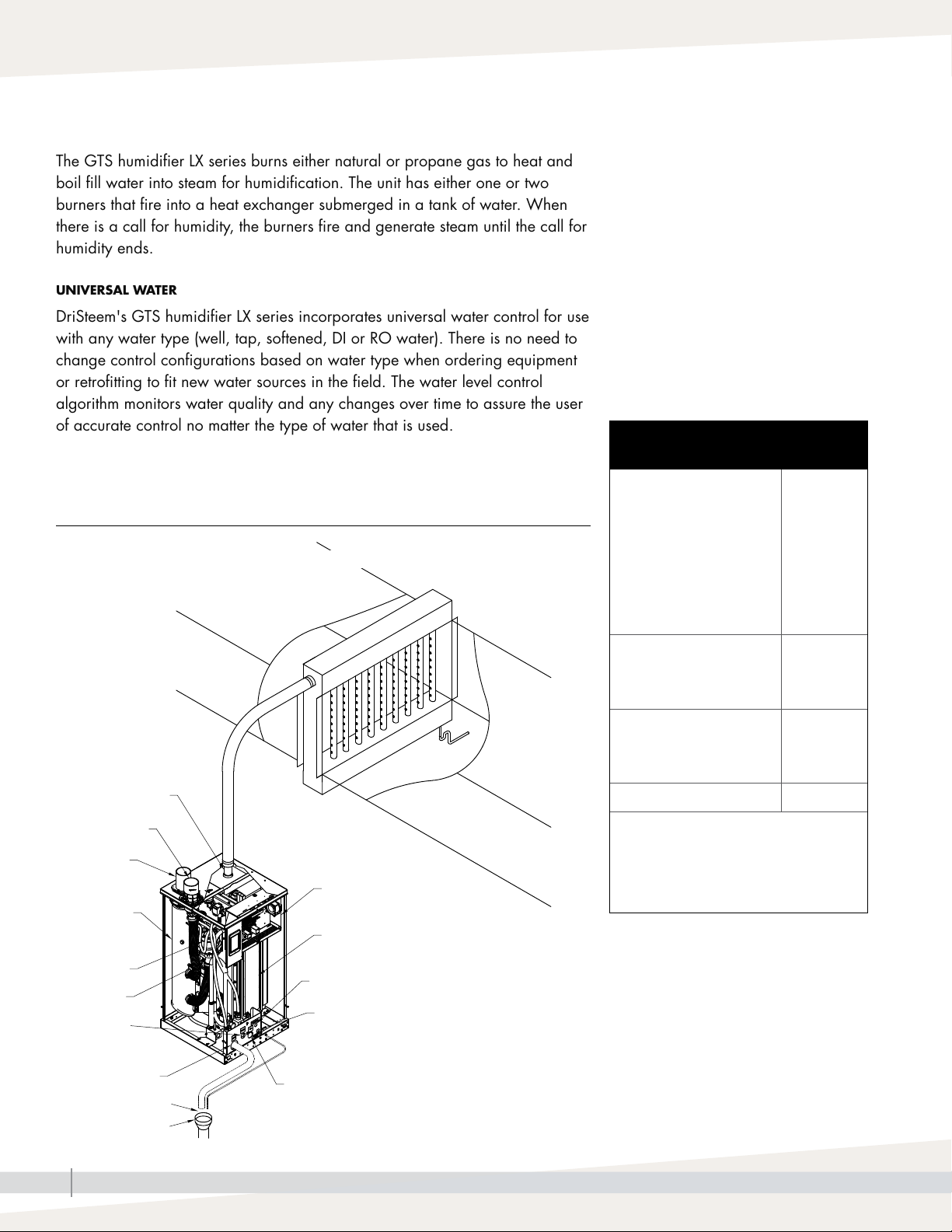
The GTS humidifier LX series burns either natural or propane gas to heat and
boil fill water into steam for humidification. The unit has either one or two
burners that fire into a heat exchanger submerged in a tank of water. When
there is a call for humidity, the burners fire and generate steam until the call for
humidity ends.
UNIVERSAL WATER
DriSteem's GTS humidifier LX series incorporates universal water control for use
with any water type (well, tap, softened, DI or RO water). There is no need to
change control configurations based on water type when ordering equipment
or retrofitting to fit new water sources in the field. The water level control
algorithm monitors water quality and any changes over time to assure the user
of accurate control no matter the type of water that is used.
PRODUCT OVERVIEW
Product overview
Supply water guidelines
FIGURE 8-1: GTS HUMIDIFIER LX SERIES
Duct dispersion option shown: Ultra-sorb Model LV
Supply water guidelines
Supply water quality is an important component
of humidifier reliability and maintenance.
Examples:
• Corrosive water can decrease the service life
of the humidifier.
• Excessive water hardness can increase the
humidifier maintenance requirements.
To maximize humidifier service life and
minimize humidifier maintenance, DriSteem has
established guidelines for supply water. See
Table 8-1.
Table 8-1:
DriSteem supply water guidelines
Chlorides*
Tap water
RO/DI water
Softened water
* Damage caused by
chloride corrosion is
not covered by your
DriSteem warranty.
Total hardness
Tap water < 500 ppm
< 50 ppm
< 5 ppm
< 25 ppm
(29 gpg)
Steam outlet
Combustion air
intake
Flue gas
vent
Control components
Secondary
heat
exchanger
Blower
Gas valve
Supply
water
connection
Open drain
Drain
Air gap
Primary heat exchanger
Electrical field connection
Flue gas condensate
Gas connection
OM-7942
GTS HUMIDIFIER LX SERIES INSTALLATION, OPERATION, AND MAINTENANCE MANUAL
8
pH
Tap water
RO/DI, softened water
6.5 to 8.5
7.0 to 8.0
Silica < 15 ppm
Supply water outside of the guidelines
may void your DriSteem warranty.
Please contact your DriSteem
Representative or DriSteem Technical
Support if you need advice.
Page 11
Product overview
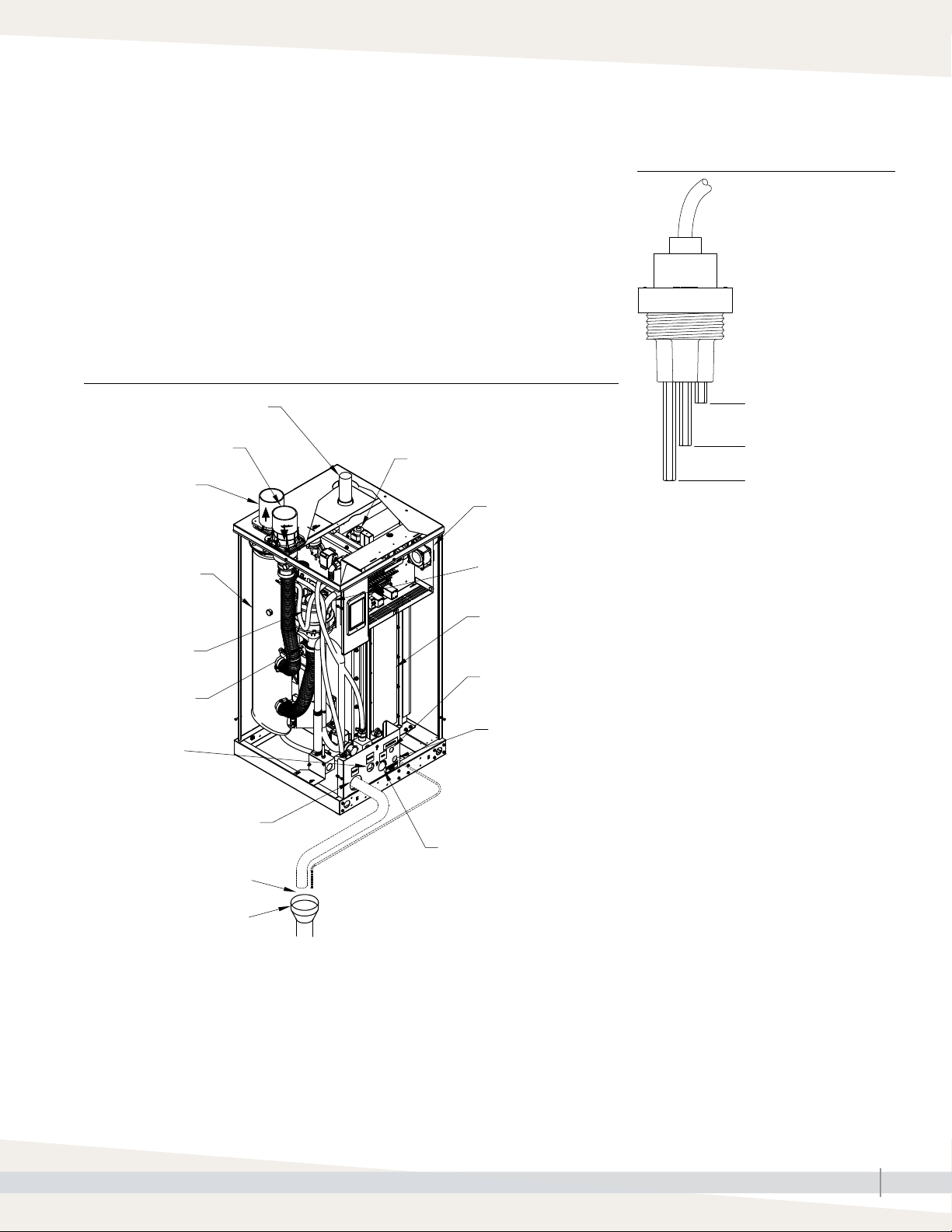
WATER LEVEL CONTROL
The LX series of GTS humidifiers control water level using a three-rod probe
(see Figure 9-1). All water types and conductivities work with the universal
water system. The user does not need to select a new water type or change
hardware to change water types. Additional valves and Vapor-logic algorithms
measure and control the water level for optimum efficiency and low water
safety conditions. Vapor-logic automatically provides a steady output while
maintaining the water level between the bottom and middle probes.
FIGURE 9-2: GTS HUMIDIFIER LX SERIES (MODELS LX-50 THROUGH LX-150)
Steam outlet
Combustion air pipe
Flue gas vent
Secondary heat
exchanger
Water level sensing probe
Control
components
Overflow
outlet
FIGURE 9-1: WATER LEVEL CONTROL
Water level
is controlled
electronically using
three probes
Overflow/foam detection
Full
Low
VLC-OM-030
Blower
Gas valve
Supply water
connection
Drain
Air gap
Open drain
Note: Dashed lines indicate supplied by installer
Primary heat
exchanger
Electrical field
connection
Flue gas condensate
Gas connection
OM-7943
GTS HUMIDIFIER LX SERIES INSTALLATION, OPERATION, AND MAINTENANCE MANUAL
9
Page 12
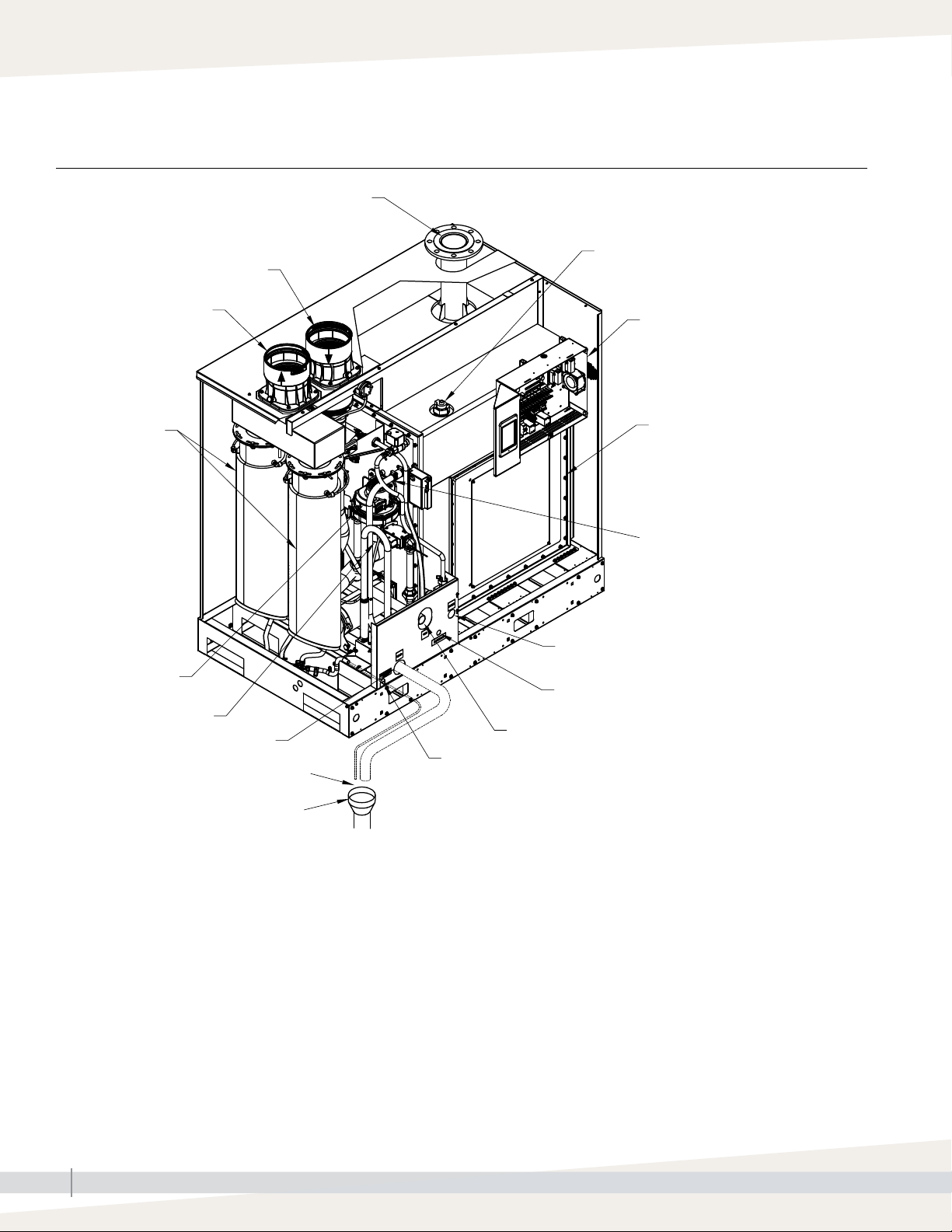
Product overview
FIGURE 10-1: GTS HUMIDIFIER LX SERIES (MODELS LX-400 THROUGH LX-600)
Steam outlet
Flue gas vent
Secondary heat
exchanger
Blower
Combustion air pipe
Gas valve
Drain
Open drain
Air gap
Water level sensing probe
Control
components
Primary heat
exchanger
Overflow
outlet
Supply water
connection
Electrical field
connection
Gas connection
Flue gas condensate
OM-7996
Note: Dashed lines indicate supplied by installer
GTS HUMIDIFIER LX SERIES INSTALLATION, OPERATION, AND MAINTENANCE MANUAL
10
Page 13
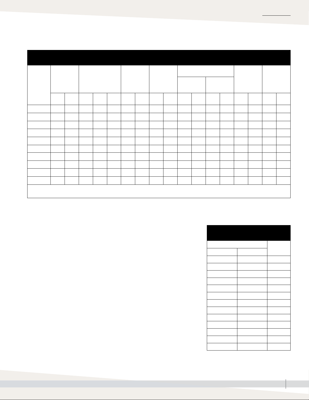
SPECIFICATIONS
Models, capacities, electrical specifications, and weights
Table 11-1:
GTS models, capacities, electrical specifications, turndown, and weights
GTS humidifier
Maximum
GTS
model
LX-50 50 23 61 17.8 1.7 6 23 14 53 304 138 187 85 5:1 10 2.0 1.5
LX-75 75 34 91.5 26.8 2.5 9 34 14 53 304 138 187 85 6:1 12.5 2.0 1.5
LX-100 100 45 122 35.8 3.4 12 45 13 49 300 136 192 87 8:1 12.5 2.0 1.5
LX-150 150 68 183 53.6 5.1 18 68 25 95 450 204 242 110 6:1 25 2.5 2.0
LX-200 200 91 244 71.5 6.8 24 91 42 159 706 320 356 161 6.7:1 30 4.0 2.5
LX-250 250 113 305 89.4 8.5 30 114 42 159 706 320 356 161 8.3:1 30 4.0 2.5
LX-300 300 136 360 105.5 10 36 136 41 155 709 321 367 166 10:1 30 4.0 2.5
LX-400 400 181 488 143 13.5 48 182 80 303 1259 571 593 269 13.3:1 30 6.5 3.5
LX-500 500 227 610 178.8 16.9 60 227 80 303 1259 571 593 269 16.7:1 30 6.5 3.5
LX-600 600 272 720 211 20 72 273 78 295 1265 574 615 279 20:1 30 6.5 3.5
* For outdoor enclosures, see Table 26-1.
** Add approximately 60-90 lbs (27-41 kg) for packaging material.
steam
capacity
lbs/hr kg/h MBh kW m
Input
3
/h
Water usage
at maximum
capacity
gals/hrlitres/
hr
Tank
volume
gals litres lbs kg lbs kg ratio lbs/hr
LX series*
Operating
weight
Shipping
(empty)
weight**
Turndown
Full load
120V
60 Hz
amps*
230V
50 Hz
LP GAS
All models operate at rated input
HIGH ALTITUDE
The input shown6 in Table 11-2 is derate when operating units at a high
altitude. See the "Start-up procedure" on page 57 for adjusting oxygen
levels on the LX series gas valve.
Important: See Pages 80 and 81 for
additional European model specifications and
capacity notes.
Table 11-2:
High altitude derate
Altitude
feet meters
0–2000 0–610 0
2001–2500 610–765 2
2501–3000 765–915 4
3001–3500 915–1065 6
3501–4000 1065–1220 8
4001–4500 1220–1370 10
4501–5000 1370–1525 12
5001–5500 1525–1675 14
5501–6000 1675–1830 16
6001–6500 1830–1980 18
6501–7000 1980–2135 20
7001–7500 2135–2285 22
7501–8000 2285–2440 24
Input
derate %
GTS HUMIDIFIER LX SERIES INSTALLATION, OPERATION, AND MAINTENANCE MANUAL
11
Page 14
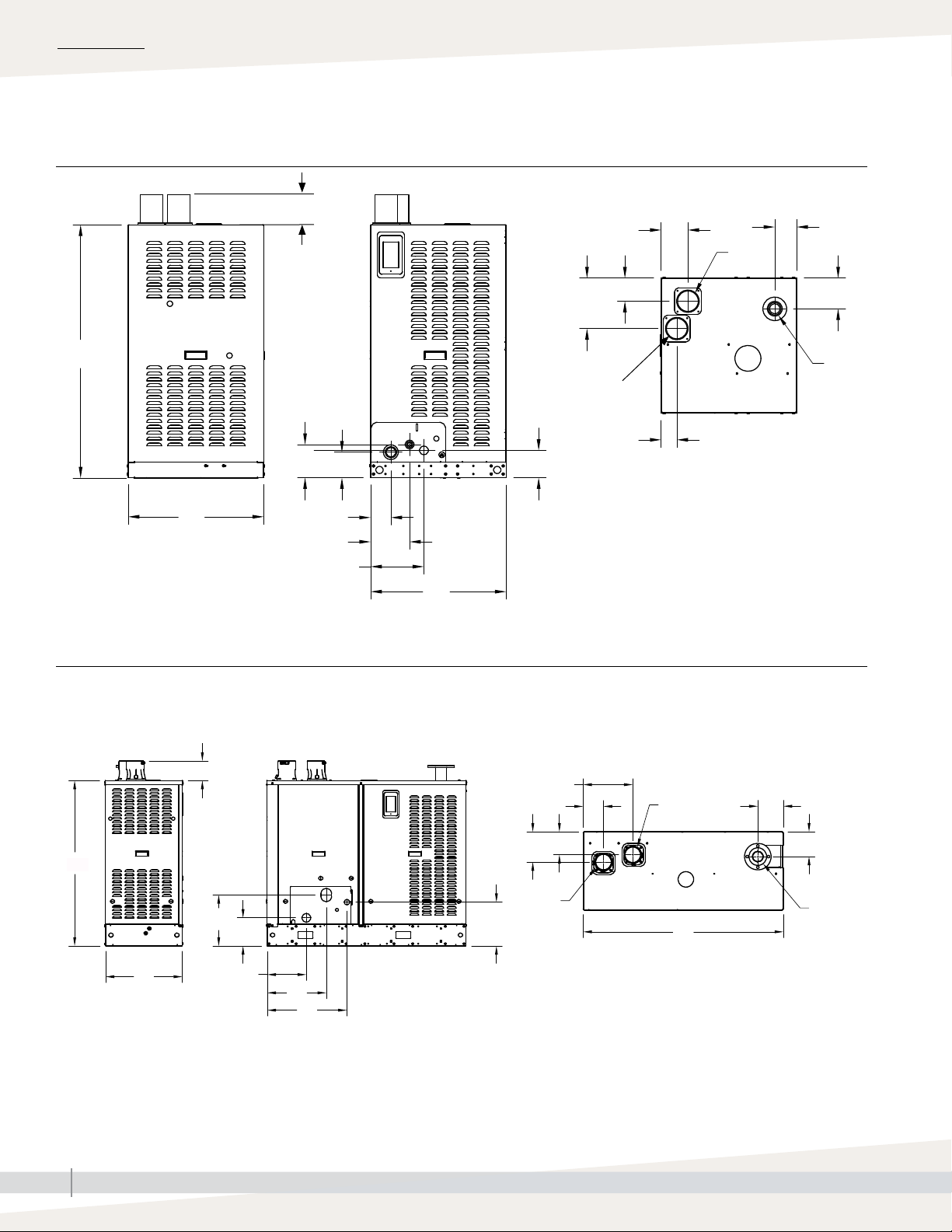
SPECIFICATIONS
Indoor dimensions
FIGURE 12-1: LX MODELS 50 - 150 INDOOR UNIT DIMENSIONS
Side view Front view Top view
C
B
See "Indoor unit dimensions" on page 13-1.
R
E
F
D
O
Q
P
T
L
N
M
S
K
A
J
G
H
J
OM-7946
FIGURE 12-2: LX MODELS 200 - 300 INDOOR UNIT DIMENSIONS
Side view Front view Top view
R
C
L
N
B
See "Indoor unit dimensions" on page 13-1.
M
T
K
S
P
E
O
D
F
Q
A
G
H
J
OM-8014
GTS HUMIDIFIER LX SERIES INSTALLATION, OPERATION, AND MAINTENANCE MANUAL
12
Page 15
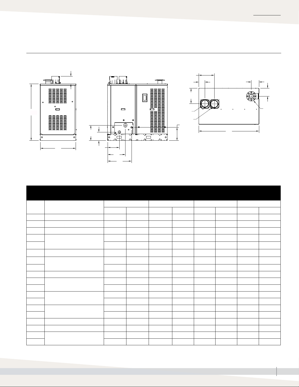
Indoor dimensions
FIGURE 13-1: LX MODELS 400 - 600 INDOOR UNIT DIMENSIONS
Side view Front view Top view
R
SPECIFICATIONS
P
E
G
D
C
B
For outdoor dimensions see page 21.
L
N
M
K
S
F
Q
T
A
OM-7998
Table 13-1:
Indoor unit dimensions
Description
A Overall length 23.25 590 32.25 819 56 1422 56 1422
B Overall width 23.25 590 23.25 590 22 559 34 864
C Overall height 42.75 1085 42.75 1085 47 1194 53 1346
D
Flue position
E 4.4 112 4.4 112 5.61 143 5.6 142
F Flue diameter 3 76 3 76 4 102 6 152
G
Steam outlet position
H 5.3 135 5.3 135 6.9 175 7.4 188
J Steam outlet diameter 2 51 2 51 3 76 4 102
K
Gas inlet position
L 4.6 119 4.6 119 14.3 363 14.3 363
M
Drain position
N 4.5 114 4.5 114 8 203 8 203
O
Combustion air
P 2.7 69 2.7 69 14 363 14.5 368
Q Combustion air diameter 3 76 3 76 4 102 6 152
R Flue and combustion air height 5.5 140 5.5 140 5.6 142 7.1 180
S
Fill valve connection position
T 5.60 142 5.60 142 12.4 315 12.4 315
LX-50, LX-75, LX-100 LX-150 LX-200, LX-250, LX-300 LX-400, LX-500, LX-600
inches mm inches mm inches mm inches mm
4.3 109 4.3 109 8.7 221 14.5 368
3.8 97 3.8 97 7.1 180 7 178
9.2 234 9.2 234 16.6 4022 16.6 422
3.5 89 3.5 89 11 279 11 279
8.92 227 8.92 227 6.5 165 14.5 368
6.59 167 6.59 167 22.4 569 22.4 569
H
J
GTS HUMIDIFIER LX SERIES INSTALLATION, OPERATION, AND MAINTENANCE MANUAL
13
Page 16
INSTALLATION
Location and clearance recommendations
FINDING A LOCATION
• Provide a level, solid foundation for the humidifier.
• The GTS humidifier LX series vent and air piping can be installed through
the roof or through a sidewall. Use only vent/air piping methods described
in this IOM. Locate the humidifier as near as possible to an outside wall
or accessible roof space so that the flue pipe from the humidifier is short,
direct, and limited to wind exposure.
• Locate the unit so it and its electrical components are protected from water
during humidifier operation and service.
• Install the humidifier in a location away (and protected) from drafts. Follow
the instructions concerning combustion and ventilation air.
• Locate the humidifier in an area where leakage from the tank or its
connections will not result in damage to the adjacent structure or to lower
floors of the structure. When such locations cannot be avoided, install
a suitable drain pan (adequately drained) under the humidifier (field
supplied). The pan must not restrict combustion airflow.
WARNING
Installation requirements
The humidifier must be installed by
a qualified technician and meet the
requirements of all governing codes.
Failure to follow these instructions could
cause severe bodily injury or death.
• If located in an insulated space, keep the humidifier free and clear of
insulating materials. Insulating material can be combustible. Inspect the
humidifier area when the humidifier is installed or when insulation is
added.
• See the combustion air and flue gas venting section on page 42 for
pipe termination locations and instructions.
GTS HUMIDIFIER LX SERIES INSTALLATION, OPERATION, AND MAINTENANCE MANUAL
14
Page 17
Location and clearance recommendations
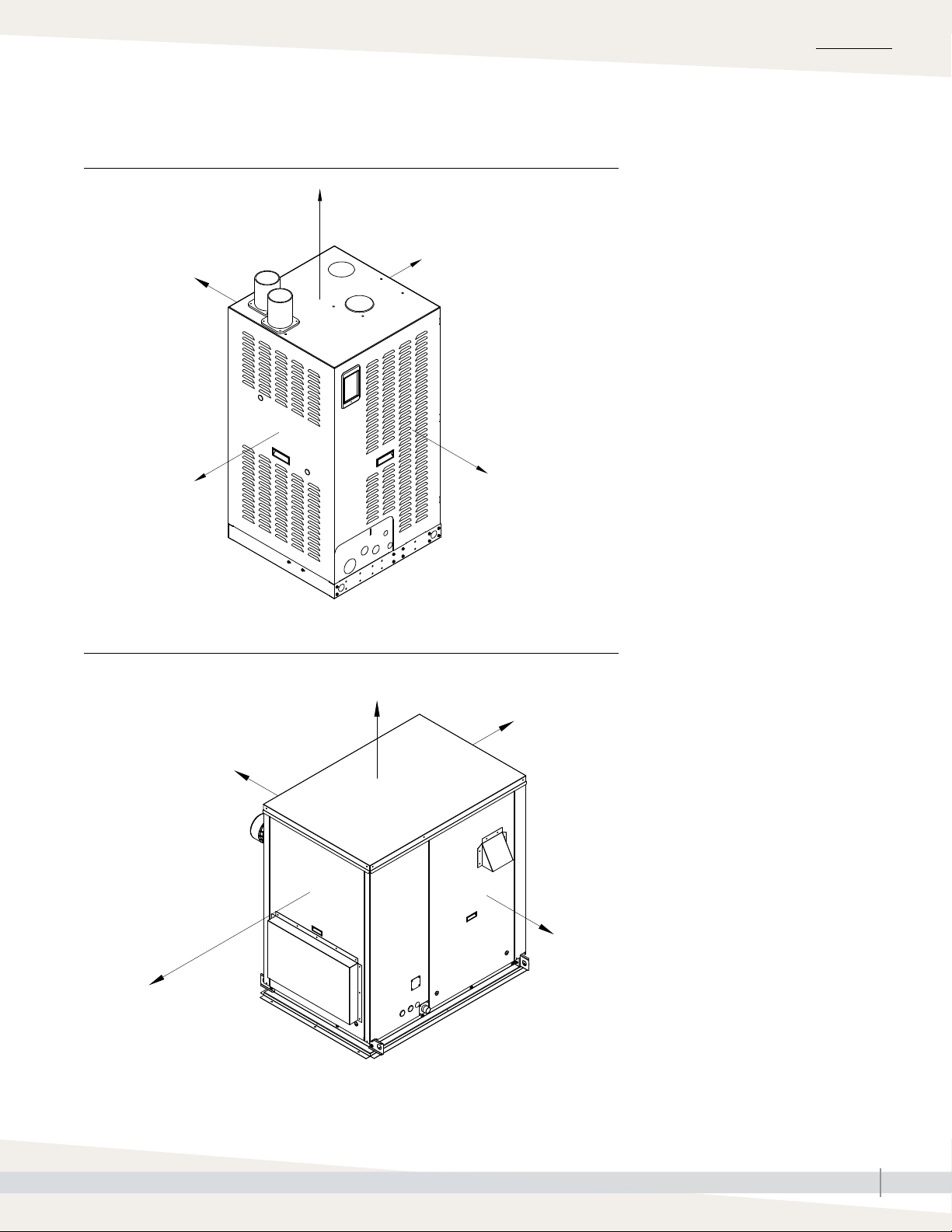
FIGURE 15-1: LX SERIES CLEARANCE RECOMMENDATIONS (INDOOR UNITS)
18" (457 mm)
Indoor Unit
INSTALLATION
1" (25 mm)
30" (762 mm) for
LX-50 through LX-150
54" (1372 mm) for
LX-200 through LX-600
FIGURE 15-2: LX SERIES CLEARANCE RECOMMENDATIONS (OUTDOOR UNITS)
Outdoor Unit
36" (914 mm)
1" (25 mm)
36" (914 mm)
OM-7947
36" (914 mm)
36" (914 mm) for
LX-50 through LX-150
54" (1372 mm) for
LX-200 through LX-600
36" (914 mm)
36" (914 mm)
OM-8012
GTS HUMIDIFIER LX SERIES INSTALLATION, OPERATION, AND MAINTENANCE MANUAL
15
Page 18
INSTALLATION
Optional floor stand mount (Models 50, 75,100, and 150 only)
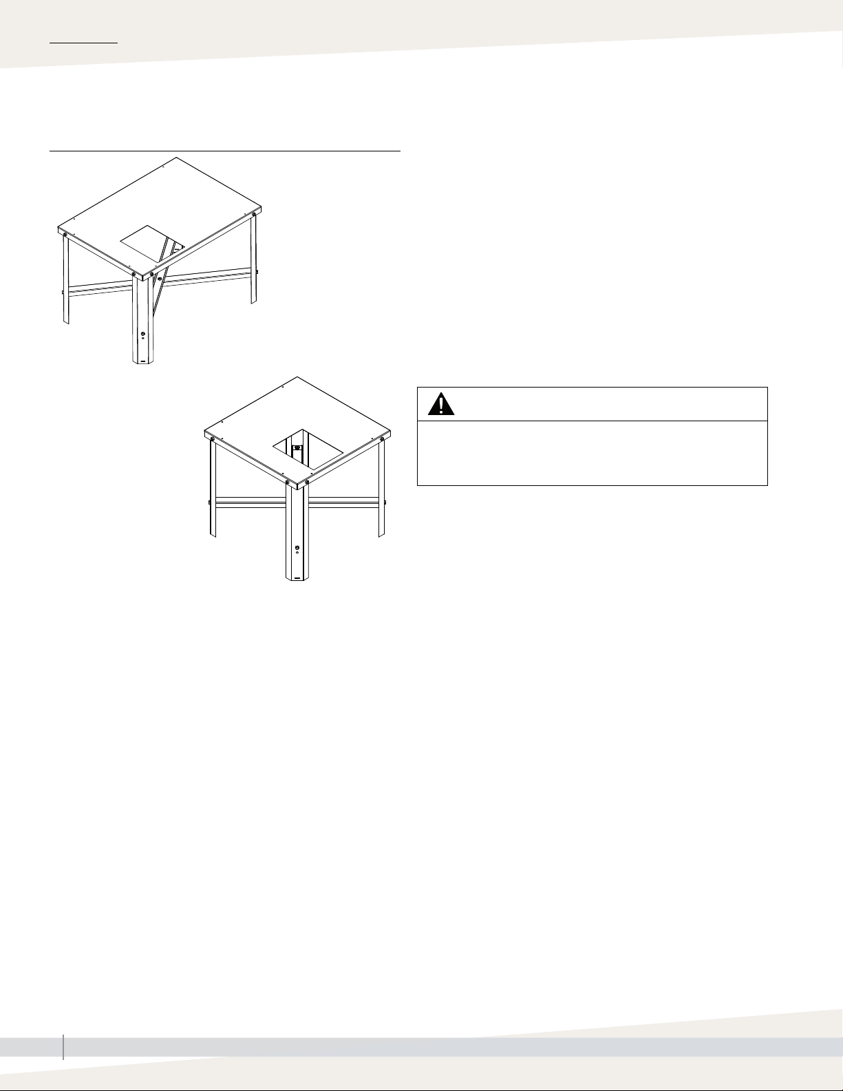
FIGURE 16-1: LX SERIES FLOOR STAND MOUNT ASSEMBLY FLOOR STAND MOUNTING INSTRUCTIONS
Model LX-150
1. Refer to Figure 17-1 for assembly of the floor stand.
2. Use the hardware provided by DriSteem to assemble.
3. Arrange appropriate lifting mechanism and personnel
to mount the GTS humidifier LX series on the floor
stand. See Warning below.
4. Use the lifting hole on the base of humidifier to
carefully lift it off the ground. See Warning below.
OM-7972
Models LX-50 - LX-100
OM-7971
5. Slowly lower the humidifier on the floor stand.
6. Secure the base of the humidifier to the floor stand
using sheet metal screws.
WARNING
HEAVY OBJECT
To avoid muscle strain or back injury, use lifting aids and
proper lifting techniques when removing or replacing.
Notes:
• Weight of floor stand:
Models LX-50 - LX-100: 24 lbs (11 kg),
Model LX-150: 30 lbs (14 kg)
• Allows for condensate piping/pump
• Bottom supply water connection is located underneath the side
water connection. See fill valve connection position on page 13.
GTS HUMIDIFIER LX SERIES INSTALLATION, OPERATION, AND MAINTENANCE MANUAL
16
Page 19
INSTALLATION
Optional floor stand mount (Models 50, 75,100, and 150 only)
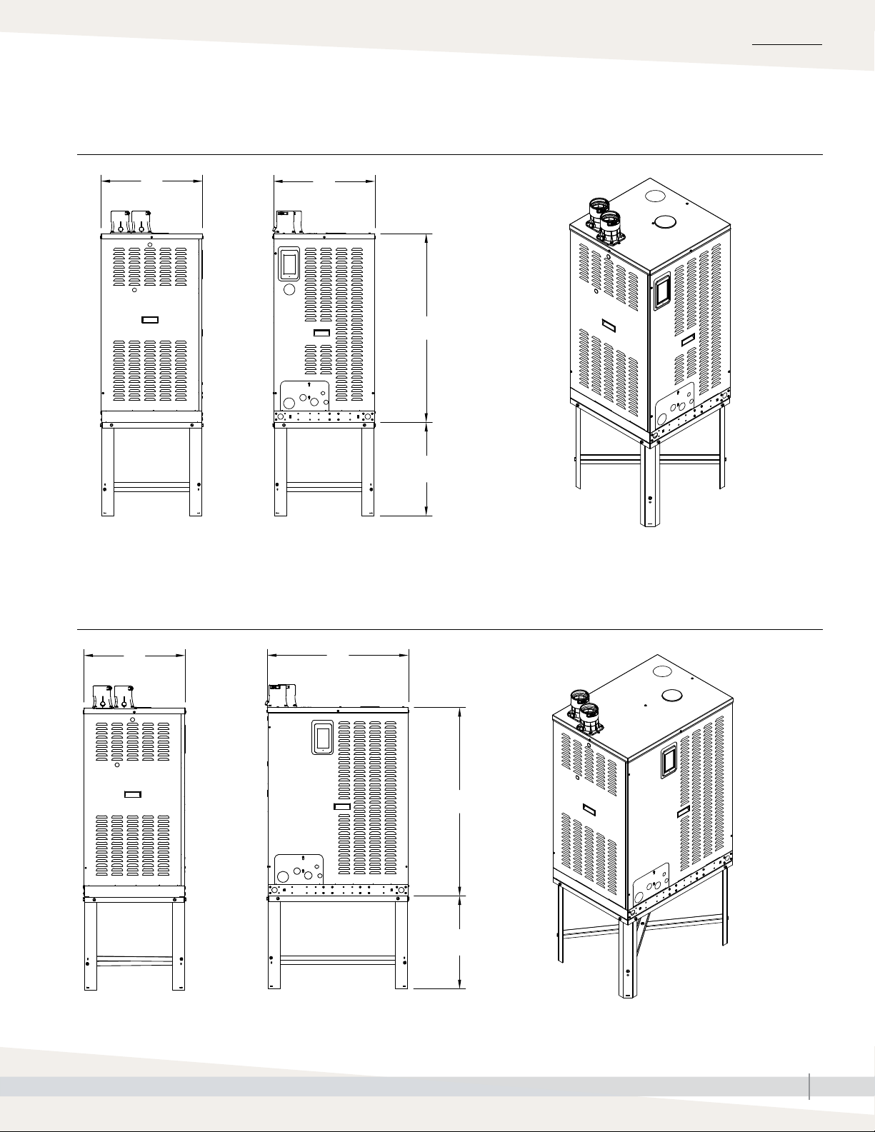
FIGURE 17-1: LX SERIES WITH FLOOR STAND MOUNT (MODELS 50, 75, AND 100)
B
See "Indoor unit dimensions" on page 13-1.
A
C
21.125" (537mm)
OM-7970
OM-7962
FIGURE 17-2: LX SERIES WITH FLOOR STAND MOUNT (MODEL 150)
B
See "Indoor unit dimensions" on page 13-1.
A
C
21.125" (537mm)
OM-8021
OM-8022
GTS HUMIDIFIER LX SERIES INSTALLATION, OPERATION, AND MAINTENANCE MANUAL
17
Page 20
INSTALLATION
Optional wall mount (Models 50, 75 and 100 only)
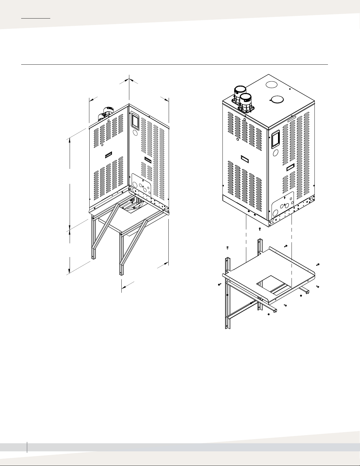
FIGURE 18-1: LX SERIES WITH WALL MOUNT
42.75"
(1086 mm)
20.13"
(511 mm)
23.13" (587 mm)
22.88" (581 mm)
See "Indoor unit dimensions" on page 13-1.
24.63" (626 mm)
OM-7993
OM-7992
GTS HUMIDIFIER LX SERIES INSTALLATION, OPERATION, AND MAINTENANCE MANUAL
18
Page 21
INSTALLATION
Outdoor enclosure
GENERAL DESCRIPTION
Overview
• The outdoor GTS is CSA/ETL approved for installation outdoors. It uses an
optional heater and fans to properly operate in operating temperatures of
-40 ºF to 122 ºF (-40 ºC to 50 ºC). The unit is intended to be mounted on
a concrete pad or rooftop curb. Properly sized curbs are available from
DriSteem.
• The knockouts located on the front of the unit are used to run electrical
power and gas to the unit. There is a pipe chase located inside the
enclosure that is used for both the supply water and drain piping. Supply
water and drain piping will need to come through the knockouts at the front
of the unit if the chase cannot be used. Combustion air is drawn from within
the enclosure, and flue gas is vented out the back of the enclosure.
• An emergency drain is provided on the front of the unit. In case of a water
leak, water drains onto the roof through this emergency drain. The drain is
intended to have a field installed water seal.
• If constant monitoring of the unit is desired, or if the unit is located in a
severe climate, install a remote mount display. Additional cable lengths up
to 500’ (152 m) are available as an option.
• In cold climates, Freeze Protection Piping (see page 25), is an important
component to the proper operation of the outdoor humidifier.
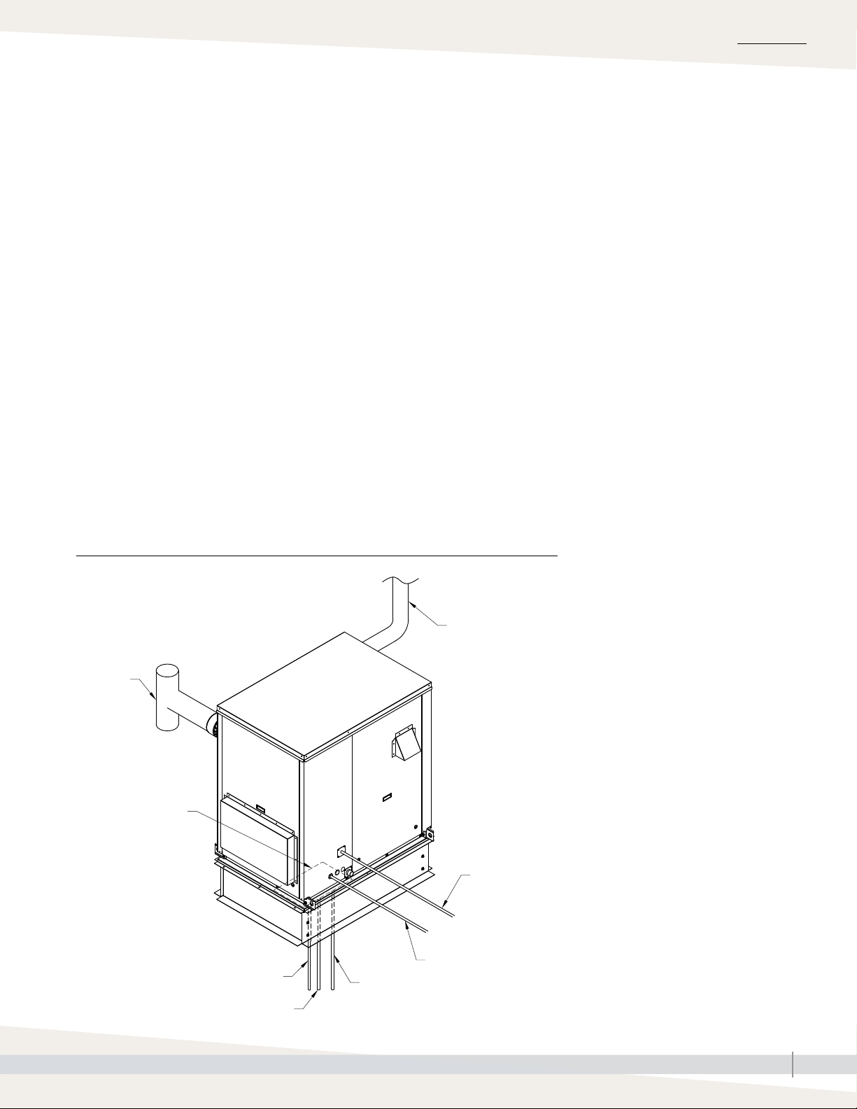
FIGURE 19-1: OUTDOOR ENCLOSURE TYPICAL INSTALLATION OVERVIEW
Steam outlet to
rooftop AHU
dispersion
Flue vent
Pipe chase
Gas piping
Flue condensate drain
Drain piping
Electrical
Fill
connections
OM-8004
GTS HUMIDIFIER LX SERIES INSTALLATION, OPERATION, AND MAINTENANCE MANUAL
19
Page 22

INSTALLATION
Outdoor enclosure: Operation
If the ambient temperature in the enclosure is below 50 ºF (10 ºC), the heater
is powered up. The heater remains powered up until the enclosure reaches
50 ºF (10 ºC). When there is no call for humidity, an aquastat maintains tank
temperature at the factory default of 50 ºF (10 ºC). This temperature can be
reset in the field to be from 50-180 ºF (10-82 ºC). If for any reason the tank
temperature falls below 40 ºF (4 ºC), the tank will drain to keep the unit from
freezing.
When the temperature of the enclosure reaches 85 ºF (29 ºC), the ventilation
fans turn on to cool the electronic components. If the enclosure temperature
reaches 150 ºF (66 ºC), the Vapor-logic controller will extinguish any
operating burners and allow the ventilation fans to cool the enclosure. When
the enclosure temperature falls below 150 ºF (66 ºC), the GTS humidifier
automatically resumes normal operation.
GTS HUMIDIFIER LX SERIES INSTALLATION, OPERATION, AND MAINTENANCE MANUAL
20
Page 23
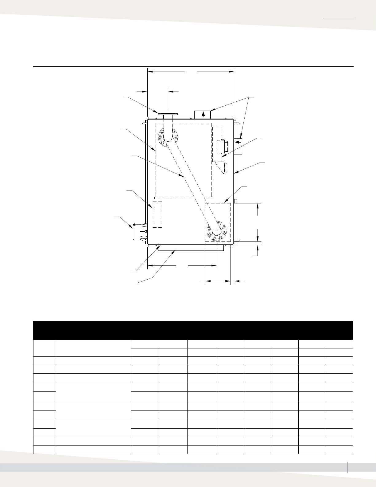
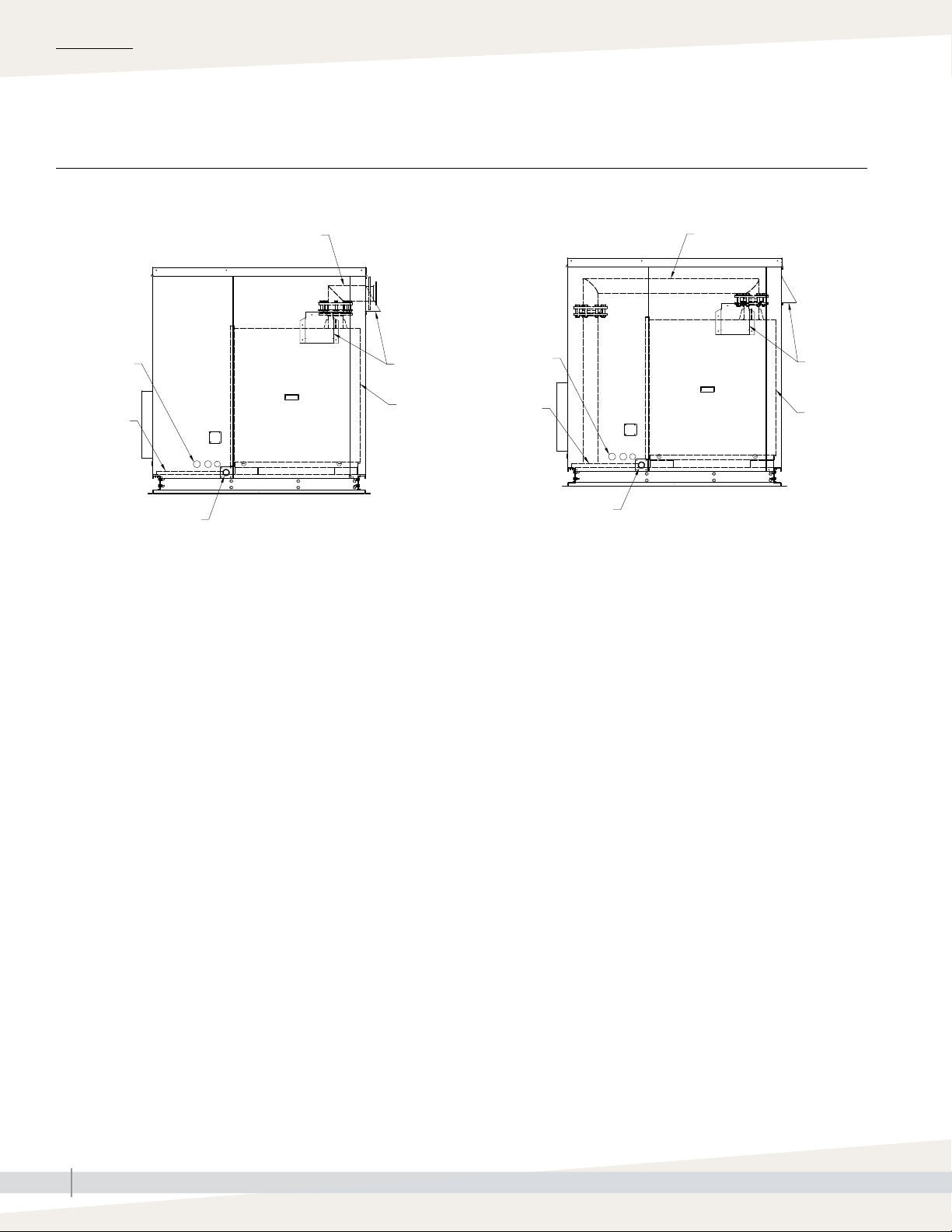
Outdoor enclosure: Dimensions
FIGURE 21-1: OUTDOOR ENCLOSURE TOP VIEW
INSTALLATION
B
Exit for standard steam outlet
GTS humidifier LX series
Exit for optional steam outlet
(through pipe chase)
Heater
Flue (by installer)
Access panel door
Air intake
H
J
F D
Ventilation fans
Control cabinet
Access panel door
Pipe chase
G
E
OM-8010
DIMENSIONS
• For outdoor unit weights, see Table 11-1.
• For clearances, see Figure 15-1.
Table 21-1:
Outdoor unit dimensions
Description
A Enclosure length 36 914.4 45 1143 57.35 1456.59 57.35 1456.59
B Enclosure width 27.35 694.7 27.35 694.7 27.35 694.69 39.10 993.04
C Enclosure height 57 1447.8 57 1447.8 62 1574.8 62 1574.8
D
Pipe chase position
E 6.51 165.28 6.51 165.3 2.048 52.02 2.05 52.04
F
Pipe chase size
G 11 279.4 11 279.4 16 406.4 16 406.4
H
Steam pipe position
J 22.61 574.2 21.33 541.76 22.16 562.84 31.48 799.36
K Curb height 14.0 - 36.0 356 - 914 14.0 - 36.0 356 - 914 14.0 - 36.0 356 - 914 14.0 - 36.0 356 - 914
L Height to bottom of flue outlet 47.0 1194 47.0 1194 45.0 1143 45.0 1143
LX-50, LX-75, LX-100 LX-150 LX-200, LX-250, LX-300 LX-400, LX-500, LX-600
inches mm inches mm inches mm inches mm
2.05 52.02 2.05 52.02 2.425 61.60 2.05 52.02
7 177.8 7 177.8 10 254 10 254
6.96 176.78 6.96 176.79 9.214 234.04 8.965 227.61
GTS HUMIDIFIER LX SERIES INSTALLATION, OPERATION, AND MAINTENANCE MANUAL
21
Page 24
INSTALLATION
Outdoor enclosure: Location
• The following information is not intended to supersede any requirements of
federal, state, or governing codes having jurisdiction; prior to locating the
unit, authorities having jurisdiction should be consulted.
• The GTS must be level and located so there is enough clearance for
opening the access panels (see recommended clearances on Page 15).
• Do not locate unit in areas where the surrounding air has high levels of
particulates, such as some industrial parks or areas near highways. In
situations such as these, you will need to filter the air inlets.
• The unit should be located so prevailing winds do not blow into the air
intakes.
• When located on the roof, the air intakes must be a minimum of 14”
(360mm) off the roof to prevent intake of snow or splashed rain.
• Locate unit so air intakes are not too close to other exhaust fan outlets,
gasoline storage, or other contaminants that could potentially cause
dangerous situations. Using and storing gasoline or other flammable vapors
and liquids in open containers near this appliance is hazardous.
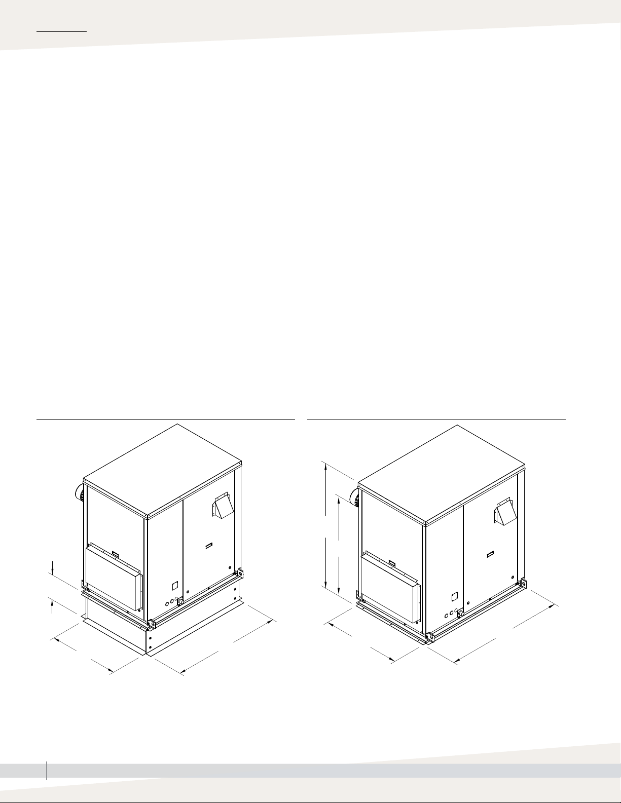
FIGURE 22-1: OUTDOOR ENCLOSURE MOUNTED ON A CURBBFIGURE 22-2: OUTDOOR ENCLOSURE MOUNTED FLUSH
C
L
K
A
B
A
OM-8008 OM-8009
GTS HUMIDIFIER LX SERIES INSTALLATION, OPERATION, AND MAINTENANCE MANUAL
22
Page 25
Outdoor enclosure: Mounting
• Verify that the position of the pad or curb properly supports the unit and
that support structure dimensions coincide with unit dimensions.
• DriSteem rooftop curbs are shipped knocked down for ease of transporting
to the roof. The curb is manufactured out of 14-gauge galvanized steel
and is shipped with all hardware for bolt-together assembly, a curb gasket
for sealing between the curb and the unit, and an installation drawing. All
holes are matched before leaving the factory.
• Roof curbs supplied by others must be at least 14” high, and there must
be a gasket between the top of the curb and the base surface of the unit to
prevent moisture from leaking into the building from either driving rain or
melting snow.
• Prior to installation, remove all of the unit packaging.
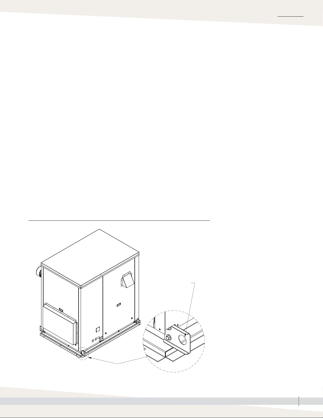
• The GTS outdoor enclosure must be lifted by the lift plates (See Figure
23-1) on the base of the unit. It must be lifted in a fashion that holds it
level and keeps it from tipping, falling, or twisting.
INSTALLATION
• If the unit is severely twisted during handling, permanent damage can
occur.
• It is the installer’s responsibility to verify the handling equipment’s
capability to safely handle the unit.
• All lifting operations must be accomplished with a load spreader of
sufficient width to ensure that the lifting cables clear the side of the unit.
FIGURE 23-1: OUTDOOR ENCLOSURE MOUNTING WITH LIFT BRACKET
1-1½" dia 938 mm) hole
lifting bracket in each
corner (typical of 4)
OM-8011
GTS HUMIDIFIER LX SERIES INSTALLATION, OPERATION, AND MAINTENANCE MANUAL
23
Page 26
INSTALLATION
Outdoor enclosure: Piping
FIGURE 24-1: GTS OUTDOOR ENCLOSURE WITH STANDARD OR OPTIONAL STEAM OUTLET, ELEVATION VIEW
Standard steam outlet Optional steam outlet
Steam outlet
1½" (38 mm)
knockouts 4"
(102 mm) o.c.
Pipe chase
Emergency
drain
OM-8006
Ventilation
fans
GTS LX
humidifier
See Piping beginning on Page 28 for directions on
installing water, drain, flue gas condensate, and gas
on the GTS humidifier LX series. For Outdoor Enclosure
specific items, see below.
Steam outlet
1½" (38 mm)
knockouts 4"
(102 mm) o.c.
Pipe chase
Emergency drain
FLUE GAS CONDENSATE
Ventilation
fans
GTS LX
humidifier
OM-8007
For cold climates, do not drain condensate on roof. This
will cause the condensate to freeze and back up. Follow
local code requirements.
SUPPLY WATER AND DRAIN
• Using the pipe chase
Use insulation to completely fill the area around
the pipes in the chase to maintain proper enclosure
pressure and protect unit components from elevated
moisture levels within the building; insulation must
serve as an effective vapor barrier.
Use the provided pipe chase cover to seal off the pipe
chase. Cut necessary holes, and seal after installation.
• Using the knockouts on the front of the unit
Heat trace and insulate piping if freezing temperatures
is a concern.
• Insulate supply water piping inside the unit to avoid
dripping from condensation.
• For cold climates, see Freeze Protection Piping on Page
25.
STEAM
The humidifier has two available steam distribution
configurations. The standard configuration has a steam
outlet on the right side of the enclosure. The optional
internal steam distribution configuration routes steam
within the enclosure and down through the pipe chase into
a building.
GTS HUMIDIFIER LX SERIES INSTALLATION, OPERATION, AND MAINTENANCE MANUAL
24
Page 27
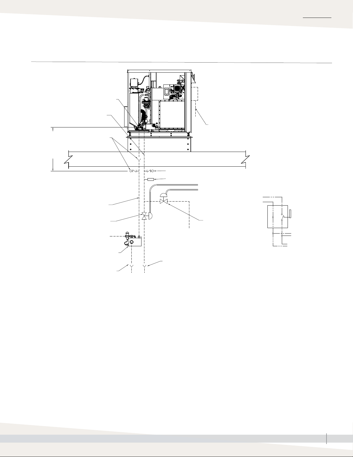
Outdoor enclosure: Freeze Protection Piping
FIGURE 25-1: OUTDOOR ENCLOSURE FREEZE PROTECTION PIPING
GTS humidifier in Outdoor Enclosure installed on rooftop
INSTALLATION
Drain connection
Supply water piping
(by installer)
Install open
drain or vacuum
breaker within
12" (305 mm)
vertical
Open drain or
vacuum breaker
(by installer)
Heated building interior
Typical drain line, min. 1½"
Normally open (fail open) minimum
8 gpm electric valve (by installer)
Domestic water, 20-80 psig
(582 kPa) maximum
Optional Drane-kooler water
tempering device
Open drain (See Note 4)
Disconnect (by installer); see Detail A
120 V supply (230 V in Europe)
Roof decking
Vacuum breaker (by installer)
Water hammer arrestor (by installer)
120 V (230 V in
Europe) from unit
disconnect or other
source (See Note 2)
Normally closed
(fail closed)
minimum
Domestic water,
20-80 psig (582
kPa) maximum
Open drain
(See Note 4)
8 gpm electric valve
(by installer)
Detail A
120 V
(230 V in
Europe)
N
Disconnect
box
To supply and drain
valves (by installer)
(See Note 2)
To GTS LX humidifier
OM-8005
Piping notes:
1. Insulate supply water piping to avoid dripping from condensation.
2. To ensure that water does not remain in the fill line and freeze if there is a loss of power, use field installed additional valves upstream of the fill
valve in a conditioned space. Power these valves on the same circuit as the GTS; if the power goes off, water drains out of the fill line to prevent
freezing (see above).
3. In extreme or critical applications in which the unlikely event of a water leak could cause severe damage, use a thermostat with a remote sensor
on the fill line to cut power to the Model LX and safety valves to stop fill water to the Model LX and drain the fill piping when the temperature is
below freezing.
4. Locate 1" air gap only in spaces with adequate temperature and air movement to absorb flash steam; otherwise, condensation may form on
nearby surfaces. Refer to governing codes for drain pipe size and maximum discharge water temperature.
5. If drain water tempering is required in the case of a power outage, install a Drane-kooler water tempering device. Pipe the cold water supplying
the Drane-kooler ahead of the field-installed additional valves mentioned in Note 2.
GTS HUMIDIFIER LX SERIES INSTALLATION, OPERATION, AND MAINTENANCE MANUAL
25
Page 28

INSTALLATION
Outdoor enclosure: Venting
See General Venting beginning on Page 42 for directions on venting. For
Outdoor Enclosure specific items, see below.
• Flue gas venting should include a 90 degree elbow and end with a tee to
the back of the unit to minimize effects of wind and prevent condensate
from dripping on to the unit. Governing codes prevail.
• Combustion air is drawn from within the DriSteem outdoor enclosure which
is sufficiently vented.
Table 26-1:
Outdoor unit amps and weights
Full Load Amps
Model
LX-50 7.0 4.5 3.0 2.5 479 217 362 164
LX-75 7.0 4.5 3.0 2.5 479 217 362 164
LX-100 7.0 4.5 3.0 2.5 475 216 367 166
LX-150 7.5 5.0 3.5 3.0 629 285 421 191
LX-200 9.0 5.5 5.0 3.5 914 415 564 256
LX-250 9.0 5.5 5.0 3.5 914 415 564 256
LX-300 9.0 5.5 5.0 3.5 916 415 574 260
LX-400 16.5 8.5 7.5 4.5 1606 729 940 426
LX-500 16.5 8.5 7.5 4.5 1606 729 940 426
LX-600 16.5 8.5 7.5 4.5 1612 731 962 436
** Add approximately 60-90 lbs (27-41 kg) for packaging material.
(Heater Package)
120V 60 Hz 230V 50Hz 120V 60Hz 230V 50Hz lbs kg lbs kg
Full Load Amps
(No Heater Package)
Operating weight Shipping (empty) weight*
GTS HUMIDIFIER LX SERIES INSTALLATION, OPERATION, AND MAINTENANCE MANUAL
26
Page 29

Wiring
INSTALLATION
WARNING
Grounding
Installation must meet the requirements of governing codes or, in the absence of
governing codes, in accordance with the National Electrical Code, ANSI/NFPA
70, or Canadian Electrical Code, CSA C22.1, or IEE wiring regulations (BS7671).
The electrical subpanel must have an uninterrupted or unbroken ground to minimize
personal injury if an electrical fault should occur. This ground can consist of electrical
wire or conduit approved for electrical ground when installed in accordance with
existing electrical codes. Do not use gas piping as an electrical ground.
• GTS humidifiers must be supplied with 120 Vac, 60 Hz (North American
models) or 230 Vac, 50 Hz (European models) separately fused electrical
service. The GTS humidifier is equipped with transformers to step down the
voltage to 24 Vac control voltage.
• When installed, the GTS humidifier must be electrically grounded in
accordance with governing codes or, in the absence of governing codes,
in accordance with the National Electrical Code, ANSI/NFPA 70; or
Canadian Electrical Code, CSA C22.1; or IEE wiring regulations (BS7671).
• In North America, the electrical conductors shall be Type MTW (105 °C)
AWG #14 (2.5 mm2) wire for 120 V line voltage , with BLACK WIRE
for HOT, WHITE WIRE for NEUTRAL, GREEN AND YELLOW WIRE for
GROUND. Units with Outdoor Enclosure must use AWG #12 (4 mm2) for
120 V line voltage. Use #18 gauge (1 mm2) for control wiring.
WARNING
Fire hazard
Do not connect aluminum wire between
disconnect switch and humidifier. Use
only copper wire. Failure to follow
these instructions could cause a fire,
resulting in severe bodily injury, death,
or significant property damage.
• In Europe, the electrical conductors shall be Type MTW (105 °C) 2.5 mm2
wire for line voltage (230V), with BLACK WIRE for LINE, BLUE WIRE for
NEUTRAL, GREEN AND YELLOW WIRE for GROUND, and 2.5 mm2 wire
for control wiring.
• All electrical components and wiring must be protected from mechanical
damage and water. The control system requires an earth ground for proper
operation.
• The GTS humidifier is adjusted for correct performance at the factory. Only
a qualified gas appliance technician may alter throttle setting.
• Check the electric current characteristics and capacity requirements against
the nameplate. All wiring must be in accordance with all governing codes
and with the GTS wiring diagrams located inside the control cabinet. See
the electrical specifications in Table 11-1 (North America) and Table
81-1 (Europe).
• Refer to the Vapor-logic Installation and Operation Manual for additional
information on the controller furnished with this GTS humidifier.
GTS HUMIDIFIER LX SERIES INSTALLATION, OPERATION, AND MAINTENANCE MANUAL
27
Page 30

INSTALLATION
Piping
FIGURE 28-1: LX SERIES FIELD PIPING OVERVIEW - MODELS LX-50 THROUGH LX-150
Shock arrester recommended to reduce
water hammer (by installer)
Steam hose or tubing
Steam outlet
Flue gas vent
Combustion air intake
7/8" (22mm) electrical field connection
Install level
Offset humidifier from floor drain to prevent
flash steam from rising into the humidifier
1" NPT (DN25) drain piping must be rated
for 212 °F (100 °C) (by installer)
1" (25 mm) air gap or
vacuum breaker
Open drain required. See first note below.
Supply water line; water pressure range
25 to 80 PSI (172 to 582 kPa); water
Install level
OM-7952
Gas inlet connection
Flue gas condensate
(see page 36)
Notes:
• Locate air gap only in spaces with adequate temperature and air
movement to absorb flash steam; otherwise, condensation may form
on nearby surfaces. Refer to governing codes for drain pipe size and
maximum discharge water temperature.
• Dashed lines indicate provided by installer.
• Humidifier flue gases must be vented to the outside atmosphere.
• Supply water inlet is more than 2" (51 mm) above skim/overflow port,
eliminating the possibility of backflow or siphoning from tank. No
additional backflow prevention is required; however, governing codes
prevail.
• For additional backflow prevention installation, install at a minimum of
40' (12 m) from the humidifier.
• Damage caused by chloride corrosion is not covered by your DriSteem
warranty.
GTS HUMIDIFIER LX SERIES INSTALLATION, OPERATION, AND MAINTENANCE MANUAL
28
Page 31

INSTALLATION
Piping:
FIGURE 29-1: LX SERIES FIELD PIPING OVERVIEW - MODELS LX-200 THROUGH LX-600
Overview
Steam hose or tubing
Steam outlet
Install level
Combustion air intake
Flue gas vent
7/8" (22mm) electrical
field connection
Shock arrester recommended to reduce
water hammer (by installer)
Supply water line; water
pressure range 25 to 80 PSI
(172 to 582 kPa); water
Install level
Flue gas condensate
(see page 36)
1" (25 mm) air gap or vacuum breaker
Open drain required. See first note below.
Notes:
• Locate air gap only in spaces with adequate temperature and air
movement to absorb flash steam; otherwise, condensation may form
on nearby surfaces. Refer to governing codes for drain pipe size and
maximum discharge water temperature.
• Dashed lines indicate provided by installer.
• Humidifier flue gases must be vented to the outside atmosphere.
• Supply water inlet is more than 2" (51 mm) above skim/overflow port,
eliminating the possibility of backflow or siphoning from tank. No
additional backflow prevention is required; however, governing codes
prevail.
• For additional backflow prevention installation, install at a minimum of
40' (12 m) from the humidifier.
• Damage caused by chloride corrosion is not covered by your DriSteem
warranty.
Gas inlet connection
Offset humidifier from floor drain to prevent
flash steam from rising into the humidifier
1½" NPT (DN40) drain piping must be
rated for 212 °F (100 °C) (by installer)
OM-7997
GTS HUMIDIFIER LX SERIES INSTALLATION, OPERATION, AND MAINTENANCE MANUAL
29
Page 32

INSTALLATION
Connection sizesPiping:
Table 30-1:
Connection sizes
Description
Gas supply 1/2 (pipe thread) 15 1/2 (pipe thread) 15 3/4 (pipe thread) 20 1 ¼ (pipe thread) 32
LX-50, LX-75, LX-100 LX-150 LX-200, LX-250, LX-300 LX-400, LX-600
inches DN inches DN inches DN inches DN
Sealed
combustion piping
Flue vent 3 80 3 80 4 100 6 150
Supply water
Drain 1 (drain block) 25 1 (drain block) 25 1 (drain block) 25 1 (drain block) 25
Steam outlet*
Flue gas
condensate
Condensate return
(recommended)
Notes:
For pipe thread steam outlet options, see DriCalc, DriSteem’s free sizing and selection software, available at www.dristeem.com.
*
STEAM PIPING SUPPORT
3/8 (pipe thread - side)
1/2 (pipe thread - bottom)1015
(all steam: hose/pipe
3 80 3 80 4 100 6 150
3/8 (pipe thread - side)
1/2 (pipe thread - bottom)1015
2
50
(all steam: hose/pipe
thread)
5/8 (OD) 18 5/8 (OD) 18 5/8 (OD) 18 5/8 (OD) 18
3/4 (pipe thread) 20 3/4 (pipe thread) 20 3/4 (pipe thread) 20 3/4 (pipe thread) 20
2
thread)
3/8 (pipe thread - side)
1/2 (pipe thread - bottom)1015
503 (all steam: flange/pipe
thread)
3/8 (pipe thread - side)
1/2 (pipe thread - bottom)1015
804 (all steam: flange/pipe
thread)
100
Support interconnecting piping between the humidifier steam outlet and the
dispersion system with pipe hangers. Failure to properly support the entire
steam piping weight can cause damage to the humidifier tank and void the
warranty.
GTS HUMIDIFIER LX SERIES INSTALLATION, OPERATION, AND MAINTENANCE MANUAL
30
Page 33

INSTALLATION
Piping:
FIGURE 31-1: LX SERIES CONDENSATE RETURN FIELD PIPING - MODELS LX-50 THROUGH LX-150
Air vent tube
6" (150 mm) minimum
Condensate return
Optional condensate return piping from dispersion unit, ¾" pipe thread
(DN20) fitting at humidifier
vent height
Condensate return
H
Use union for cleanout plate removal
Access by others
OM-8001
GTS HUMIDIFIER LX SERIES INSTALLATION, OPERATION, AND MAINTENANCE MANUAL
31
Page 34

INSTALLATION
Piping:
FIGURE 32-1: LX SERIES CONDENSATE RETURN FIELD PIPING - MODELS LX-200 THROUGH LX-600
Condensate return
Air vent tube
6" (150 mm) minimum
vent height
Optional condensate return piping from dispersion
unit, ¾" pipe thread (DN20) fitting at humidifier
Access by others
H
Condensate return
Manual drain valve (if required)
OM-8000
GTS HUMIDIFIER LX SERIES INSTALLATION, OPERATION, AND MAINTENANCE MANUAL
32
Page 35

Supply water and drain overflow connectionsPiping:
AUTOMATIC DRAIN WATER TEMPERING
The GTS humidifier LX series is shipped with drain water tempering enabled.
This feature can be disabled in the Vapor-logic controller. When drain water
tempering is enabled, the following steps will take place to ensure drain water
is less than 140°F (60 °C):
1. Water greater than 140°F (60 °C) is detected in the drain assembly with a
temperature sensor.
2. Fill valves open, directing cool water to the drain port within the tank.
3. Hot and cold water mix in the tank near the drain port.
4. Drain port valve opens and sends tempered water to the drain manifold.
5. The Vapor-logic controller controls the drain and fill valves using input
from the drain temperature sensor to enable closed-loop control of drain
water temperature, thus ensuring it does not exceed 140°F (60°C) while
minimizing water usage.
INSTALLATION
SUPPLY WATER CONNECTIONS
Regardless of the type of water used, the following general instructions MUST
be followed:
• There is one water connection to the humidifier. Water is connected in the
field to the fill water manifold. The fill water manifold provides water to the
humidifier tank and to the secondary heat exchanger. The water provided
to the tank is also used for tempering drain water.
• Make union connections at the humidifier on the make-up water supply and
drain/overflow lines.
• Provide a shutoff valve in the supply water line to isolate the humidifier from
the water system while servicing.
• A shock arrester, provided by installer, is required to reduce water hammer.
• A 2" (51 mm) air gap is provided in the humidifier tank to accommodate
skim and/or overflow protection and prevent water backflow.
• Note: Follow governing code requirements regarding size of drain pipe.
• Use insulating unions or bushings to make connections between copper and
other dissimilar metal fittings, such as galvanized steel. These insulating
fittings are required to minimize electrolytic corrosion, which results from the
direct connection of dissimilar metals in a water system.
• Before beginning ignition sequence of the humidifier at a new installation,
make sure the humidifier tank is full of water and the water is free to flow
into the tank.
• Do not use heated supply water. Using supply water over 90°F (32 °C) will
adversely effect the performance of the GTS humidifier LX series.
• Water inlet and outlet must be permanent pipe connections shown in Table
30-1. Do not connect with hose-sets or other non-permanent methods.
GTS HUMIDIFIER LX SERIES INSTALLATION, OPERATION, AND MAINTENANCE MANUAL
33
Page 36

INSTALLATION
Supply water and drainPiping:
SUPPLY WATER PIPING
• The GTS humidifier has a 2" (51 mm) internal air gap to prevent back
siphoning into a potable water system. However, some governing codes
may require additional protection such as a vacuum breaker or backflow
preventer.
• The supply water pressure range must be 25 psi to 80 psi (172 kPa to 552
kPa).
• The supply water assembly has both a 3/8" (DN10) pipe thread (side) and
1/2" (DN 15) pipe thread (bottom) connection.
• During an integral drain tempering event, cold water in the internal drop
tube may cause a low rolling sound.
• In cases where water hammer occurs when the fill solenoid closes, a shock
arrester is recommended. Reducing the supply water pressure (minimum
25 psi [172 kPa]) or using flexible tubing (rated for 212 °F [100 °C]
minimum continuous operating temperature) may diminish the noise, but
installing a shock arrester is the best solution.
• The end-of-season feature drains the tank when there is no demand for
humidity for 72 hours. (This length of time is a default setting and is
user-adjustable. See the Vapor-logic Installation and Operation Manual for
more information.)
• Supply water tubing must be rated for at least 80 psi (552 kPa) at 140°F
(60 °C) continuous service.
DRAIN
The drain line piped from the humidifier must be run to an approved sanitary
waste or suitable drain that accommodates a 12 gpm flow rate. Although
the GTS humidifier is equipped with integral water tempering, if nonmetallic
drain pipe or hose is used, it should be rated for 212 °F (100 °C) minimum
continuous operating temperature.
If vertical drop of drain exceeds 12” (305 mm) a vacuum breaker or open
drain with air gap must be installed within 12 vertical inches (305 mm) of unit.
Failure to do so will create a siphon during drain events, disrupting normal
drain operation and allowing steam to enter the drain through the overflow
p-trap outlet (see Figure 35-2).
Important: Damage caused by chloride
corrosion is not covered by your DriSteem
warranty. See “Supply water guidelines” on
Page 8.
Table 34-1:
Supply water guidelines
Supply water
pressure
Supply water
flow rate
Supply water
temperature
25-80 psi
at 6.0 gpm
flow rate
6.0 gpm 21 l/min
34°F to 90°F 1°C to 32°C
172-552 kPa
Table 34-2:
Water tempering specifications
for optional Drain-kooler water
tempering device
Maximum
Water type
Hot water
inflow
Cold water
inflow*
Tempered
water outflow
* Cold water inflow pressure must be between
25 psi and 80 psi (172 kPa and 552 kPa).
Flow rate
U.S.
gpm
L/m °F °C
6 22.7 212 100
6 22.7 90 32
12 45.4 140 60
Maximum
temperature
Ensure the drain piping configuration (diameter, length, slopes, elbows,
hangers, etc.) supports a 12 gpm flow rate for proper drain operation and to
prevent overflow and spillage from an open drain with air gap.
Do not reduce the size of the drain piping. If the length of the drain piping
exceeds 10' (3 m), increase the pipe size. If combining multiple drain lines
together, ensure proper common pipe sizing practices are used.
GTS HUMIDIFIER LX SERIES INSTALLATION, OPERATION, AND MAINTENANCE MANUAL
34
Page 37

INSTALLATION
Supply water and drainPiping:
Do not locate the humidifier directly above a floor drain — skim and drain
water dumped into the drain will cause flash steam. This steam will rise
and saturate electrical components, adversely affecting component life and
performance.
An open drain or vacuum breaker with a 1" (25 mm) air gap between the
drain piping and the drain is required. Locate air gap only in spaces with
adequate temperature and air movement to absorb flash steam; otherwise,
condensing on nearby surfaces may occur.
Drain piping after the water seal must be pitched a minimum of 1/8"/ft (1%)
toward the drain. Governing codes may require more pitch.
If the proximity of a drain requires the humidifier drain and skim water to be
lifted, use a water pump with capacity of at least 12 gallons per minute (gpm)
or 45.4 litres per minute (L/m). A check valve is required on the discharge of
the pump (see Figure 35-1). Electrical power for the pump is independent of
the humidifier.
The GTS humidifier has an auxiliary 3/4" (20 DN) drain outlet located on or
near the cleanout plate. This drain outlet can be hard-piped during installation
to enable rapid tank draining before maintenance. This outlet can also provide
access for removing scale from the tank bottom. If this connection is used,
install a union to facilitate removal of the cleanout plate.
Drain water tempering
Governing codes may require that the 212 °F
(100 °C) drain and skim/overflow water
from the humidifier be tempered before it is
discharged into the building drain piping. The
GTS humidifier has closed loop integral drain
tempering.
Integral tempering sequence:
1. Water greater than 140 °F (60 °C) is
detected in the drain manifold with a
temperature sensor.
2. Tank fill valve opens and directs cold
water through the tank and toward the
drain.
3. Drain valve opens and sends tempered
water to the drain manifold.
4. Feedback from the drain manifold
temperature sensor will open/close the
drain valve/fill valves to maintain a
maximum of 140 °F (60 °C) in the drain
manifold.
FIGURE 35-1: LIFTING DRAIN WATER FIGURE 35-2: VERTICAL DRAIN
Inlet drain water piping, by installer
Water pump
Note: Size water pump to handle a minimum of 12 gpm (45.4 L/m).
Discharge piping, by installer
Check valve
DC-1117
Install open drain or
vacuum breaker within
12" (305 mm)
Greater than
12" (305 mm)
OM-8023
Open
drain or
vacuum
breaker
(by
installer)
GTS HUMIDIFIER LX SERIES INSTALLATION, OPERATION, AND MAINTENANCE MANUAL
35
Page 38

INSTALLATION
Flue gas condensatePiping:
FLUE CONDENSATE PIPING GUIDELINES
• Follow local code requirements for discharge of condensate. The flue gas
condensate will have a 2-4 pH range and may need to be treated prior to
discharge.
• Minimum drain pipe size is 5/8" inside diameter.
• If treatment is needed, DriSteem offers a condensate neutralizer kit.
The neutralizer should be installed per manufacturer instructions below
condensate p-trap level. Avoid obstructions as condensate could be
damaging to surrounding surfaces and articles.
• Prime the condensate p-trap at the base of the secondary heat exchanger.
FIGURE 36-1: GTS SEALED COMBUSTION CONNECTION
- MODELS LX-50 THROUGH LX-150
Combustion air intakeFlue gas vent to outside
24" (607 mm)
6" - 8"
(152 - 203 mm)
Flue gas condensate
½" (13 mm)
Notes:
1. Use flexible tubing that is rated for acidic condensate.
2. All tubing must allow flow away for humidifier to condensate
neutralizer (if equipped).
3. Condensate neutralizer should be installed per manufacturer
instructions below the condensate p-trap level.
4. If floor drain is greater than 5' (1.5 m) from humidifier, use a
5/8" PVC pipe instead of a hose.
5/8" secondary
heat exchanger
condensate
Optional
condensate
neutralizer
5/8" (16 mm)
Open
drain
OM-7967
GTS HUMIDIFIER LX SERIES INSTALLATION, OPERATION, AND MAINTENANCE MANUAL
36
Page 39

Flue gas condensatePiping:
FIGURE 37-1: GTS SEALED COMBUSTION CONNECTION - MODELS LX-200 THROUGH LX-600
Combustion air intake
Flue gas vent to outside
INSTALLATION
Optional
condensate
neutralizer
5/8" (16 mm) secondary
heat exchanger condensate
Notes:
1. Use flexible tubing that is rated for acidic condensate.
2. All tubing must allow flow away for humidifier to condensate
neutralizer (if equipped).
3. Condensate neutralizer should be installed per manufacturer
instructions below the condensate p-trap level.
4. If floor drain is greater than 5' (1.5 m) from humidifier, use a ½"
PVC pipe instead of a hose.
GTS HUMIDIFIER LX SERIES INSTALLATION, OPERATION, AND MAINTENANCE MANUAL
5/8" (16 mm)
Open
drain
OM-7995
37
Page 40

INSTALLATION
Piping:
GAS PIPING GUIDELINES
Gas
• After threading and reaming the ends of the pipes, inspect piping and
remove loose dirt and chips.
• Support piping so there are no strains imposed on unit or controls.
• Use two wrenches when tightening piping to unit or controls.
• Provide a drip pocket before each unit and in the line where low spots
cannot be avoided.
• Takeoff to unit should come from top or side of main to avoid trapping
condensate.
• Piping that is subject to wide temperature variations should be insulated.
• Pitch piping up toward unit at least 1/4" (6 mm) per 15' (4.5 m) of
horizontal run.
• Compounds used on threaded joints of gas piping must be resistant to the
harmful action of liquefied petroleum gases.
WARNING
Fire or explosion hazard
Purge air before lighting unit by disconnecting piping at gas control. In no case should
line be purged into heat exchanger. Failure to follow these instructions could cause a
fire or explosion, resulting in bodily injury, death, or significant property damage.
WARNING
Fire hazard
Supply the humidifier only with the
gas type (natural gas or LP gas) listed
on the humidifier name plate. Failure
to supply the humidifier with the listed
gas type could result in burner failure
or a fire, causing property damage,
personal injury, or death.
To convert the humidifier to natural
gas or LP gas, contact DriSteem
Technical Support or your DriSteem
Representative/Distributor.
Important: For North American models,
the recommended supply pressure is 7" wc
(1.75 kPa) for natural gas or 11" wc (1.83
kPa) for LP gas.
For European models, the required supply
pressure is 20 or 25 mbar for natural gas and
30, 37, or 50 mbar for propane gas.
• After installation, check field piping and humidifier gas train for gas leaks.
• Do not use soap solution or open flame on humidifier gas train. A gas leak
detector is recommended.
• Install a ground joint union and a manual shutoff valve immediately
upstream of the unit. Install a plugged tapping upstream of the shut-off
valve, accessible for test gauge connection (see Caution).
• Allow at least 5' (1.5 m) of piping between any high pressure regulator
and unit pipe connection.
• Piping installation must conform to the requirements of the authority having
jurisdiction or, in the absence of such requirements, must conform to:
• In the United States: The National Fuel Gas Code, ANSI Z223.1
(latest edition).
• In Canada: Local plumbing or waste water codes and other applicable
codes and with the current code CAN/CGS-B149.1, “Installation
Code for Natural Gas Burning Appliances and Equipment,” or CAN/
CGA-B149.2, “Installation Code for Propane Burning Appliances and
Equipment.”
• In Europe: The National Gas Safety (Installation & Use) Regulations.
CAUTION
Install connection for gas pressure test
gauge
Gas pressure to the humidifier controls
must never exceed 24" wc (6 kPa, 60
mbar), or the gas valve will become
damaged and require replacement.
The gas pressure diagnostic port on
the gas valve can be used to check
pressure. Loosen the screw and push
a 5/16" ID hose over the fitting
connected to a gauge. Remove the
hose and tighten the screw when
finished.
Install a 1/8" pipe thread (DN6)
plugged tapping, accessible for
test gauge connection, immediately
upstream of the gas supply connection
to the appliance.
GTS HUMIDIFIER LX SERIES INSTALLATION, OPERATION, AND MAINTENANCE MANUAL
38
Page 41

INSTALLATION
Gas (continued)Piping:
• Piping to units should conform with local and national requirements for
type, volume, and gas handled and for pressure drop allowed in the line.
Refer to the tables on this page to determine the gas flow in ft3/hr or m3/hr
for the type of gas and size of unit to install. Using this value and the length
of pipe necessary, determine the pipe diameter. Where several units are
served by the same main, the total capacity, gas flow, and length of main
must be considered. Avoid pipe sizes smaller than 1/2" (DN15). Table
39-2 allows for the usual number of fittings with a 0.3" wc (0.07 kPa)
pressure drop.
• When the specific gravity of the gas is other than 0.60 for natural gas or
1.53 for propane, use Table 39-1.
Table 39-2:
Gas pipe capacities for gas pressures of 0.5 psig (3.45 kPa) or less
3
/hr and m3/hr at pressure drop of 0.3" wc (0.07 kPa)
Specific gravity = 0.60
Nominal iron pipe diameter in inches (DN)
Length of
pipe
ft m ft
Gas flow in piping in ft
1/2" (DN15) 3/4" (DN20) 1" (DN25) 1¼" (DN32) 1½" (DN40)
3
/hr m3/hr ft3/hr m3/hr ft3/hr m3/hr ft3/hr m3/hr ft3/hr m3/hr
Table 39-1:
Specific gravity conversion factors
Natural gas
Specific gravity Factor
0.55 1.04
0.60 1.00
0.65 0.962
Propane gas
Specific gravity Factor
1.50 0.633
1.53 0.626
1.60 0.612
Note:
Use the above multiplying factor with Table:
39-2 when the specific gravity of gas
is other than 0.60 (natural gas) or 1.53
(propane).
10 3 132 3.7 278 7.9 520 14.7 1050 29.7 1600 45.3
20 6 92 2.6 190 5.4 350 9.9 730 20.7 1100 31.1
30 9 73 2.1 152 4.3 285 8.1 590 16.7 890 25.2
40 12 63 1.8 130 3.7 245 6.9 500 14.2 760 21.5
50 15 56 1.6 115 3.3 215 6.1 440 12.5 670 19.0
60 18 50 1.4 105 3.0 195 5.5 400 11.3 610 17.3
70 21 46 1.3 96 2.7 180 5.1 370 10.5 560 15.9
80 24 43 1.2 90 2.5 170 4.8 350 9.9 530 15.0
90 27 40 1.1 84 2.4 160 4.5 320 9.1 490 13.9
100 30 38 1.1 79 2.2 150 4.2 305 8.6 460 13.0
See example on page 40
GTS HUMIDIFIER LX SERIES INSTALLATION, OPERATION, AND MAINTENANCE MANUAL
39
Page 42

INSTALLATION
Gas (continued)Piping:
EXAMPLE
For this example, refer to the tables on Page 39.
To determine gas piping size, begin by calculating the cubic feet/hour (ft3/hr)
or m3/hr using the following formula:
• Btuh (kW) input / calorific value of gas
Calorific values are:
• Natural gas: 1025 Btu/ft3 (10.6 kW-hr/m3)
• Propane: 2500 Btu/ft3 (25.9 kW-hr/m3)
For example, if you have a LX-150 operating on natural gas, calculate the ft3/
hr or m3/hr as follows:
• 183,000 Btuh / 1025 Btu/ft3 = 390 ft3 per hour
• 117.2 kW / 10.6 kW-hr/m3 = 11.1 m3 per hour above your calculated
ft3/hr or m3/hr. In this example, you are looking for the next highest
value above 390 ft3/hr (11.05 m3/hr), which is 400 ft3/hr (11.3 m3/hr)
and indicates the use of a 1¼" (DN32) pipe for this application.
Using the same example, if the specific gravity of your natural gas was 0.55
(instead of the 0.60 standard), see Table 39-2 for an adjustment factor.
In this case, the factor would be 1.04, which you multiply by the 390 ft3/hr
(11.05 m3/hr) value. This gives you a new value of 406 ft3/hr (11.49 m3/hr).
Referring again to Table 39-2, you see that for the same 60 ft (18 m) length,
you now need to use 1½" (DN40) pipe due to the change in the specific
gravity of the gas.
Gas leak testing
• When leak-testing the gas supply piping
system, disconnect the humidifier and its gas
shutoff valve during any pressure in excess
of 24" wc (6 kPa). Isolate the humidifier from
the gas supply piping system by closing its
field-installed manual shutoff valve during
any pressure not equal to 24" wc (6 kPa).
• With the burner running at full capacity,
check gas supply pressure at the inlet
pressure tap of the combination gas control
valve.
For North American models, the
recommended supply pressure is 7" wc
(1.75 kPa) for natural gas or 11" wc (1.83
kPa) for LP gas. Perform gas piping purging
as described in ANSI Z223.1 (latest edition)
or in Canada, CAN/CGA-B149 codes. The
minimum supply pressure is 6" wc (1 kPa) for
natural gas or LP gas.
For European models, the required supply
pressure is 20 or 25 mbar for natural gas
and 30, 37, or 50 mbar for propane gas.
GTS HUMIDIFIER LX SERIES INSTALLATION, OPERATION, AND MAINTENANCE MANUAL
40
Page 43

Gas (continued)Piping:
FIGURE 41-1: GTS GAS PIPING
All Models
INSTALLATION
See page 30 for connection sizes
OM-7953
Drip pocket
Manual gas shutoff valve
Plugged test gauge connection
3” (76 mm) min.
GTS HUMIDIFIER LX SERIES INSTALLATION, OPERATION, AND MAINTENANCE MANUAL
41
Page 44

INSTALLATION
General venting
The GTS humidifier is pre-plumbed to support both room air and sealed
combustion. See Warning. Requirements and recommendations for each
follow.
ROOM AIR COMBUSTION
• All fuel burning equipment must be supplied with air for combustion of
the fuel. Sufficient air must be provided to ensure there is not a negative
pressure in the equipment room or space.
• Provide adequate combustion and ventilation air in accordance with
Section 5.3, Air for Combustion and Ventilation, of the National Fuel
Gas Code, ANSI Z223.1 or applicable provisions of governing codes.
Canadian installations must be installed in accordance with sections 7.2,
7.3, and 7.4 of the CAN/CGA.B149 Installation Codes and all authorities
having jurisdiction.
• For proper and safe operation this humidifier needs air for combustion and
ventilation. Do not block or obstruct air openings on the appliance, spaces
around the appliance, or air openings communicating with the humidifier
area.
WARNING
Air for combustion
Air for combustion must not be
contaminated by halogen compounds,
which include fluoride, chloride,
bromide, and iodide. These elements
are found in aerosol sprays, detergents,
bleaches, cleaning solvents, salts,
air fresheners, chlorine and other
household products.
When the GTS is located in an
environment with negative pressure or
toxic air, pipe the sealed combustion
connection to fresh supply air at
atmospheric pressure.
Failure to follow these instructions could
cause severe bodily injury or death.
• Do not locate in a dusty environment.
• Do not block the flow of combustion and ventilation air. To provide for
necessary oxygen for proper combustion, openings must be provided
to allow outside air to enter the space where the humidifier is located.
Enclosed spaces, such as equipment rooms, must be vented for combustion
air. The size of air openings must be based on all gas-burning equipment
installed in the space involved. Table 42-1 outlines four types of
locations, and the requirements of each.
Table 42-1:
Location of humidifier and required air openings (non-ducted combustion air)
Location description Required air opening
2
Confined space with all air from inside the building;
conventional frame, brick or stone construction
with normal infiltration (Note: this location rarely
provides enough air for higher capacity units.)
Confined space with all air from outside the
building through air ducts
Confined space with all air from outside the
building from through-wall openings only (no ducts)
Unconfined space with all air from outside the
building
* The minimum dimension of any opening is 3" × 3" (76 mm × 76 mm).
Two openings, 1 sq. in. (6.5 cm
opening per 1000 Btu/hr (293 W) input
The minimum free area of all openings
combined is 100 sq. in. (645 cm2).
Two openings, 2 ducts, 1 sq. in. (6.5 cm
per opening per 2000 Btu/hr (586 W)
input*
Two openings, 1 sq. in. (6.5 cm
opening per 4000 Btu/hr (1172 W) input*
Same as confined space; all air from outside
the building
) per
2
) per
WARNING
Do not interfere, disable, or tamper
with the devices monitoring the
combustion gas discharge, including
the flue temperature and flue pressure
sensors. Only authorized and trained
technicians should perform any
service on these items. If the unit fails
repeatedly due to a discharge (flue)
fault, have the device serviced and
2
)
tested by authorized and trained
technicians.
GTS HUMIDIFIER LX SERIES INSTALLATION, OPERATION, AND MAINTENANCE MANUAL
42
Page 45

INSTALLATION
General venting (continued)
WARNING
Combustion air quality (list of contaminants)
Sample list of contaminants to be avoided:
The recommended source of combustion air is to use the outdoor air supply. However, the use of indoor air in most applications is
acceptable except as follows:
1. If the furnace is installed in a confined space it is recommended that the necessary combustion air come from the outdoors by
way of attic, crawl space, air duct, or direct opening.
2. If outdoor combustion air is used, there must be no exposure to the installations or substances listed in “3” below.
3. The following types of installation may require OUTDOOR AIR for combustion, due to chemical exposures:
• Commercial buildings
• Buildings with indoor pools
• Furnaces installed in laundry rooms
• Furnaces installed in hobby or craft rooms
• Furnaces installed near chemical storage areas
Exposure to the following substances in the combustion air supply may also require OUTDOOR AIR for combustion:
• Permanent wave solutions
• Chlorinated waxes and cleaners
• Chlorine based swimming pool chemicals
• Water softening chemicals
• De-icing salts or chemicals
• Carbon tetrachloride
• Halogen type refrigerants
• Cleaning solvents (such as perchloroethylene)
• Printing inks, paint removers, varnishes, etc.
• Hydrochloric acid
• Cements and glues
• Antistatic fabric softeners for clothes dryers
• Masonry acid washing materials
GTS HUMIDIFIER LX SERIES INSTALLATION, OPERATION, AND MAINTENANCE MANUAL
43
Page 46

INSTALLATION
General venting (continued)
FIGURE 44-1: ROOM AIR COMBUSTION FOR THE LX-50, LX-75, AND 100
Flue gas vent to outside
Quantity of two 2" (60 mm) 90° elbows
24" (607 mm)
6" - 8" (152 - 203 mm)
Flue gas
condensate
To drain or
condensate
neutralizer
Note: Field piping supplied by others.
Bird screen
3" to 2" (80 to 60 mm)
reducer (user installed)
3" (80 mm) air intake)
See Table 48-1 for
flue venting sizes and
lengths.
OM-7978
CAUTION
Flue condensate removal
(For Models LX-50 - LX-300 only).
Install a drip tee within the first 3' (1 m)
of flue venting for flue condensate
removal. Failure to follow these
instructions could reduce the service
and efficiency of the secondary heat
exchanger.
If flue vent is less than 10' (3 m) long
and a sidewall exit, then no drip tee
needed.
FIGURE 44-2: ROOM AIR COMBUSTION FOR THE MODELS LX-150, 200, AND 300
Flue gas vent to outside
Quantity of two elbows
24" (607 mm)
Bird screen
6" - 8" (152 - 203 mm)
Flue gas
condensate
See Table 48-1 for
To drain or
condensate
neutralizer
Note: Field piping supplied by others.
OM-7979
flue venting sizes and
lengths.
GTS HUMIDIFIER LX SERIES INSTALLATION, OPERATION, AND MAINTENANCE MANUAL
44
Page 47

General venting (continued)
FIGURE 45-1: ROOM AIR COMBUSTION FOR THE LX-400, LX-500, AND LX-600
INSTALLATION
No drip tee required
Flue gas vent to outside
Quantity of two 90° elbows
(See Table 48 for vent size)
Bird screen
See Table 48-1 for
flue venting sizes and
lengths.
OM-8020
GTS HUMIDIFIER LX SERIES INSTALLATION, OPERATION, AND MAINTENANCE MANUAL
45
Page 48

INSTALLATION
General venting (continued)
SEALED COMBUSTION (COMBUSTION AIR FROM OUTSIDE THE BUILDING)
• The GTS is pre-plumbed to support sealed combustion using PVC, CPVC
ABS, polypropylene, or stainless steel or piping (see Figure 46-1).
All GTS models have a single point connection on top of the humidifier
shroud.
• When running piping for sealed combustion, see Tables 48-1 and
49-1 for maximum and minimum equivalent length of vent pipe and
equivalent length of each elbow (maximum of eight elbows including
terminations). The outside air source can be either a final connection
outside the building or a connection to an outdoor air plenum within
the building. When the combustion air origination point is outside the
building, the opening must be covered with a large mesh screen to prevent
the introduction of unwanted materials without restricting airflow.
• If sealed combustion piping passes through warm, conditioned space
insulate piping to prevent condensation.
WARNING
Requirement for manifolding sealed
combustion piping runs
When installing sealed combustion
piping for more than one GTS
humidifier, do not commonly manifold
multiple sealed combustion piping
runs without having the manifold
sized for the specific installation by
a licensed engineer. Failure to follow
these instructions could starve the GTS
humidifier of combustion air resulting
in either the unit not being able to light
or high carbon monoxide (CO) levels,
which may cause severe personal injury
or death.
FIGURE 46-1: LX SERIES SEALED COMBUSTION CONNECTION
Flue gas vent to outside
Flue
Tee
24" (607 mm)
6" - 8"
(152 - 203 mm)
Flue gas
condensate
To drain
Combustion air intake
PVC or CPVC
combustion air intake
OM-7977
Note: Field piping supplied by others.
GTS HUMIDIFIER LX SERIES INSTALLATION, OPERATION, AND MAINTENANCE MANUAL
46
Page 49

General venting (continued)
GUIDELINES
• The GTS is a Fan Assisted Category IV (condensing, positive pressure)
Appliance.
• Maximum flue temperature is 140 °F (60 °C).
• Vent piping must be UL or UL/CSA listed PVC, CPVC, polypropylene or any
other vent type approved for a Category IV appliance.
• Follow supplier fitting and cement/primer instructions to ensure proper fit,
adhesion, and assembly.
• Clean and seal inlet piping per the pipe manufacturer's recommended
solvents and cements. Follow manufacturer's recommended procedures
for pipe and fitting preparation, cutting and attachment with appropriate
solvents and cements for the material.
• Insulate sealed combustion piping to avoid dripping from condensation.
• Do not use vent equipment from more than one application/manufacturer.
• Do not insulate the flue vent piping.
• Installation must be in accordance with Part 7, Venting of Equipment, of
the National Fuel Gas Code, ANSI Z223.1; or Section 7, Venting Systems
and Air Supply Appliances, of the CAN/CGA B149 Installation Codes; or
National Gas Safety Code (Installation & Use) Regulations (latest revision);
governing codes, and the vent manufacturer’s instructions.
INSTALLATION
WARNING
Installation requirements
The humidifier must be installed by
a qualified technician and meet the
requirements of all governing codes.
Failure to follow these instructions could
cause severe bodily injury or death.
Note:
For European models, contact your distributor
for horizontal venting parts.
WARNING
Installation requirements
Failure to properly seal all joints and
seams as required in the air inlet piping
may result in flue gas recirculation,
spillage of flue products and carbon
monoxide emissions causing sever
personal injury or death.
Table 47-1:
Approved PVC/CPVC flue gas vent pipe and fittings
Item Vent material United States Canada
PVC ANSI/STM D2665
PVC, Sch. 40 ANSI/ASTM D1785
Piping
Fittings
Cement,
primer
Note: Do not use cellular (foam) core PVC, DWV pipe, ASTM F891, or cellular core CPVC or
RADEL (Polyphenylsulfone).
PVC, SDR series ANSI/ASTM D2241
CPVC, Sch. 40 ANSI/ASTM F441
CPVC, SDR series ANSI/ASTM F422
PVC, DWV, Sch. 40 ANSI/ASTM D2665
PVC, Sch. 40 ANSI/ASTM 2466
PVC, Sch. 80 ANSI/ASTM 2467
CPVC, Sch. 40 ANSI/ASTM F438
CPVC, Sch. 80 ANSI/ASTM F439
PVC ANSI/ASTM D2564
CPVC ANSI/ASTM F493
IPEX system
1738
ULC S636
Table 47-2:
Approved vent manufacturers
Item Manufacturer
Polypropylene
Stainless steel
* For 2", 3", and 4" vent pipe only.
Centrotherm Eco Systems*
DuraVent (M&G Group)
DuraVent (M&G Group)
Z-Flex
Heat Fab
Metal Fab
Security Chimney
GTS HUMIDIFIER LX SERIES INSTALLATION, OPERATION, AND MAINTENANCE MANUAL
47
Page 50

INSTALLATION
General venting (continued)
• When applying the codes, reference also the venting manufacturer's instructions, the service gas
supplier's regulations, and the specific instructions provided in this manual.
• Install vent piping as direct as possible, with a minimum number of turns or elbows.
• For Models LX-50 - LX-300 only: Install a drip tee within the first 3' (1 m) of flue venting for flue
condensate removal. If flue vent is less than 10' (3 m) long and a sidewall exit, then no drip tee
needed. See Figure 46-1.
• The purpose of venting the gas humidifier is to completely remove all products of combustion
and ventilation gases to the outside air.
• Maintain a minimum upward slope of 1/4" per linear foot (2%) and supported every 4' (1 m)
on all horizontal runs of the flue gas. Maintain proper support of vent connections and joints.
Observe clearances (in accordance with applicable codes) from all combustible materials.
• Inspect for proper and tight construction. Clean and remove any restrictions or obstructions. An
existing chimney may be used as a chase.
• Do not connect this humidifier to a chimney flue servicing any other appliance.
• Dedicated flue gas venting and combustion air piping must be used for each individual LX series
GTS humidifiers.
• The flue gas outlet and combustion air inlet pressures at the vent adapters on the LX series GTS
Table 48-1:
Flue vent lengths
Minimum equivalent pipe length
Model
LX-50 10 (3) 70 (21) 10 (3) 70 (21)
LX-75 5 (1.5) 30 (9) 10 (3) 30 (9) 50 (15)
LX-100 5 (1.5) 10 (3) 10 (3) 20 (6) 25 (8)
LX-150 10 (3) 10 (3)
LX-200 40 (12)
LX-250 30 (9)
LX-300 25 (8)
LX-400 50 (15)
LX-500 35 (10)
LX-600
Combustion air intake Flue gas vent Combustion air intake Flue gas vent
2"
(60
mm)
3"
(80
mm)
4"
(mm)
6"
(mm)
ft (m)
2"
(60
mm)
3"
(80
mm)
4"
(mm)
6"
(mm)
2"
(60
mm)
100
(30)
Maximum equivalent pipe length
3"
(80
mm)
250
(76)
200
(61)
150
(46)
100
(30)
4"
(mm)
175
(53)
125
(38)
100
(30)
ft (m)
6"
(mm)
200
(61)
150
(46)
100
(30)
2"
(60
mm)
100
(30)
50 (15)
25 (8)
3"
(80
mm)
250
(76)
200
(61)
150
(46)
100
(30)
40 (12)
30 (9)
25 (8)
4"
(mm)
175
(53)
125
(38)
100
(30)
50 (15)
35 (10)
6"
(mm)
200
(61)
150
(46)
100
(30)
GTS HUMIDIFIER LX SERIES INSTALLATION, OPERATION, AND MAINTENANCE MANUAL
48
Page 51

General venting (continued)
INSTALLATION
humidifier must be within the ranges shown in Table
49-2 from full output to minimum output.
• Do not common vent products of combustion the LX
series GTS humidifier with another LX series or any
other appliance.
• Flue gas outlet and combustion air inlet adapters
accept PVC, CPVC, Polypropylene and stainless steel
piping.
• Flue vent adapters, if used, must be installed vertically
at the point of connection to the GTS humidifier LX
series.
• Ensure that distances from vent terminal to adjacent
public walkways, buildings, and openable windows
and building openings are consistent with National
Fuel Gas Code, ANSI Z223.1, CAN/CGA B149
Installation Codes, National Gas Safety Code
(Installation & Use) Regulations (latest revision), or
governing codes.
• In areas accessible to the public, vent terminal must be
at least 7' (2.1 m) above ground level to prevent burns
from hot terminal surface.
Table 49-2:
Venting pressure
Description Minimum Maximum
Flue gas outlet pressure
Combustion air inlet pressure
FIGURE 49-1: VENT ELBOWS AND TEES
-0.05" WC
(+12 Pa)
-0.45" WC
(-112 Pa)
long
mitered
+0.45" WC
(+112 Pa)
+0.05" WC
(+12 Pa)
medium
• The vent terminal and air intake locations must be at
sufficient height above ground level to prevent blocking
by expected snowfall.
• Building materials must be protected from degradation
by flue gases.
Note: A maximum of eight elbows, including terminations, are allowed.
concentric
• Maintain minimum horizontal clearance of 4' (1.22 m)
from electric meters, gas meters, regulators, and relief
equipment.
Table 49-1:
Equivalent vent lengths
Description
Long radius 90° elbow 3 0.9 4 1.2 6 1.8
Medium radius 90° elbow 5 1.5 7 2.0 10 3.0
Mitered 90° elbow 8 2.4 11 3.3 16 4.9
Long radius 45° elbow 1.5 0.5 2 0.6 3 0.9
Medium radius 45° elbow 2.5 0.8 3 1.0 5 1.5
Mitered 45° elbow 4 1.2 5 1.6 8 2.4
Concentric vent termination 5 1.5 7 2.0
Tee 16 4.9 21 6.5 32 9.8
3" to 2" (80 to 60 mm) step down adapter 5 1.5 7 2.0 10 3.0
2" - 3" diameter 4" diameter 6" diameter
feet meter feet meter feet meter
GTS HUMIDIFIER LX SERIES INSTALLATION, OPERATION, AND MAINTENANCE MANUAL
49
Page 52

INSTALLATION
Vertical venting
• Never connect this humidifier to an existing chimney.
• Rigidly support the vent pipe every 3' (1 m) or less with
hangers or straps to ensure there is no movement after
installation. The humidifiers secondary heat exchanger
should not support the weight of the vent piping.
• No portion of the vent system should extend into, or
pass through, any circulation air duct or plenum.
• The vent system must terminate above the roof surface
per the National Fuel Gas Code, CAN/CGA.B149,
or National Gas Safety Code (Installation & Use)
Regulations (latest revision) requirements or governing
codes, and must include a UL or UL/CSA listed vent
cap or roof assembly, unless prohibited by governing
codes. Install a high-wind vent cap on all GTS
humidifiers.
• Install and fire-stop all vent pipe passing through floors,
ceilings, and walls with the proper clearances from
combustible material according to the National Fuel
Gas Code, Canadian Standards CAN/CGA.B149,
the National Gas Safety Code (Installation & Use)
Regulations (latest revision), or governing codes.
• In replacement installation where an existing vent
system may be used, inspect the vent system for
condition, size, type of vent material, and height to
meet the requirements in these instructions. When
connecting the humidifier to a gas vent or chimney, the
installation must be in accordance with Part 7, Venting
of Equipment, of the National Fuel Gas Code, ANSI
Z223.1; Section 7, Venting Systems and Air Supply
Appliances, of the CAN/CGA B149 Installation
Codes; The National Gas Safety Code (Installation &
Use) Regulations (latest revision), governing building
codes, and the vent manufacturer’s instructions.
FIGURE 50-1: CONCENTRIC VENT ROOF INSTALLATION
12" (305 mm) [18" (457
mm) for Canada] minimum
Vent
Combustion air
Roof boot/flashing
(field supplied)
Flue gas
clearance above highest
anticipated snow level.
Maximum of 24" (610 mm)
above roof
Support (field supplied)
Elbow
(field supplied)
Combustion air
OM-7976
GTS HUMIDIFIER LX SERIES INSTALLATION, OPERATION, AND MAINTENANCE MANUAL
50
Page 53

Vertical venting (continued)
• Ensure that distances from vent terminal to adjacent public walkways,
buildings, and openable windows and building openings are consistent
with National Fuel Gas Code, ANSI Z223.1, CAN/CGA B149 Installation
Codes, National Gas Safety Code (Installation & Use) Regulations (latest
revision), or governing codes.
• In areas accessible to the public, vent terminal must be at least 7' (2.1 m)
above ground level to prevent burns from hot terminal surface.
• The vent terminal and air intake locations must be at sufficient height above
ground level to prevent blocking by expected snowfall.
• Building materials must be protected from degradation by flue gases.
• Maintain minimum horizontal clearance of 4' (1.22 m) from electric meters,
gas meters, regulators, and relief equipment.
• See Tables 48-1 and 49-1 for maximum and minimum equivalent
length of vent pipe.
FIGURE 51-1: GTS VERTICAL VENTING
2 qty 90° elbows or tee (optional)
Bird screen
INSTALLATION
Flue gas vent (straight)
12" (305 mm)
minimum
vertically
12" (305
mm) minimum
above
roof/snow
level 24"
(610 mm)
maximum
without
additional
support
Notes:
• For Models LX-50 - LX-300 only: Install a drip tee within the first 3' (1 m) of flue venting for flue condensate removal.
If flue vent is less than 10' (3 m) long and a sidewall exit, then no drip tee needed. See Figure 46-1.
• Required distance between air intake and vent hood is defined by governing codes.
• Slope flue gas vent horizontal runs ¼"/ft (2°) back towards the tee at humidifier.
• 4' (1.2 m) minimum from any cable, dormer, or other roof structure with building interior access (e.g. vent or window).
• 10' (3 m) minimum from any forced air inlet to the building, including make up air inlets such as dryer or furnace areas.
24" (610 mm)
minimum
center to center
To drain
GTS
humidifier LX
series
Bird screen
Combustion air intake
(2 qty 90° elbows)
Bird screen
12" (305 mm) minimum above roof/
snow level 24" (610 mm) maximum
without additional support
Bird screen
Flue gas vent
(straight)
Combustion air intake
OM-7973
2 qty 90° elbows or tee
(optional)
Bird screen
2 qty 90° elbows
Bird
screen
12"
(305 mm)
minimum
vertically
OM-7975-LX
GTS HUMIDIFIER LX SERIES INSTALLATION, OPERATION, AND MAINTENANCE MANUAL
51
Page 54

INSTALLATION
Sidewall venting
DETERMINE A LOCATION
Consider the surroundings when terminating the vent and air:
• Position the vent where vapors will not damage nearby shrubs, plants, or
air conditioning equipment or be objectionable.
• The flue will form a noticeable plume as it condenses in cold air. Avoid
areas where the plume could obstruct window views.
• Prevailing winds could cause freezing of condensate and water/ice buildup
where flue products impinge on building surfaces or plants.
WARNING
A gas vent extending through an
exterior wall shall not terminate
adjacent to wall or below building
extensions such as eaves, parapets,
balconies, or decks. Failure to comply
could result in severe personal injury,
death, or substantial property damage.
• Avoid possibility of accidental contact of flue gas with people or pets.
• Do not locate the vent where wind could affect performance or cause
recirculation, such as inside building corners, near adjacent buildings or
surfaces, window wells, stair wells, alcoves, courtyards, or other recessed
areas.
• Do not locate the vent above any door or window. Condensate can freeze,
causing ice formations.
• Locate or guard vent to prevent condensate damage to exterior finishes.
• Combustion air and flue gas terminations should be seated in the same
atmospheric zones.
• In cold climate application, insulate sealed combustion air piping that
passes through warm, humid interior environments to prevent condensation.
FIGURE 52-1: GTS HUMIDIFIER LX SERIES SIDEWALL VENTING
Flue gas vent
Pitch
¼"/ft. minimum
Combustion air pipe
Pitch
¼"/ft. minimum
Sidewall vent and air inlet terminations
must terminate in the same pressure
zone.
Failure to prime all flue gas condensate
traps (tees and secondary heat
exchanger P-trap) with water will result
in combustion gas entering the living
space (which may contain carbon
monoxide).
To avoid the risk asphyxiation from
carbon monoxide, never operate the
humidifier unless the condensate drip
tees and secondary heat exchanger
P-trap are sealed with water.
CAUTION
Sidewall venting commercial products
will result in large exhaust plumes in
cold climates. Consideration should
be taken when locating in proximity to
windows, doors, walkways, etc.
OM-7983
GTS HUMIDIFIER LX SERIES INSTALLATION, OPERATION, AND MAINTENANCE MANUAL
52
Page 55

Sidewall venting (continued)
FIGURE 53-1: GTS HUMIDIFIER LX SERIES SIDEWALL VENTING
For Models LX-50 - LX-300 only: Install a drip
tee within the first 3' (1 m) of flue venting for
flue condensate removal. If flue vent is less
than 10' (3 m) long and a sidewall exit, then
no drip tee needed.
INSTALLATION
Bird screen
Flue gas vent
Bird screen
OM-7980
Bird screen
Combustion air pipe
WARNING
Do not exceed the maximum lengths
of the outside vent piping as shown
in Figure 54-1. Excessive length
exposed to the outside could cause
freezing of condensate in the vent
pipe, resulting in potential humidifier
shutdown.
GTS HUMIDIFIER LX SERIES INSTALLATION, OPERATION, AND MAINTENANCE MANUAL
53
Page 56

INSTALLATION
Sidewall venting (continued)
SIDEWALL INSTALLATION
See Figures 54-1 and Figures 54-2.
• For Models LX-50 - LX-300 only: Install a drip tee within the first 3' (1 m)
of flue venting for flue condensate removal. If flue vent is less than 10' (3
m) long and a sidewall exit, then no drip tee needed. Warning: Failure
to follow these instructions could reduce the service and efficiency of the
secondary heat exchanger.
• If total actual length of flue gas venting is less than 10' AND sidewall exit is
used, a tee is not needed.
• The combustion air piping must end in a down-turned elbow. This
arrangement avoids recirculation of flue products into the combustion air
stream.
• The flue gas vent piping may terminate in an elbow pointed outward or
away from the air inlet at least 12" (305 mm) above the combustion air
inlet, or use a tee as a termination to minimize effects of wind.
• The vent must end:
• At least 6' (1.8 m) from adjacent walls.
• No closer than 12" (305 mm) below roof overhang.
• At least 3' (0.9 m) above any forced air intake within 10' (3 m).
• No closer than 12" (305 mm) below or horizontally from any door or
window or any other gravity air inlet.
• Air inlet must be at least 12" (305 mm) above grade or snow line; at least
12" (305 mm) below the vent end; and the vent pipe must not extend
more than 24" (610 mm) vertically outside the building unless supports are
added.
FIGURE 54-2: GTS HUMIDIFIER LX
SERIES SIDEWALL VENTING
WITH CONCENTRIC VENT
Overhang or
roof
Bird screen
12" (305 mm)
12" (305 mm)
OM-7982
Grade/snow line
FIGURE 54-1: GTS HUMIDIFIER LX SERIES SIDEWALL VENTING
Maximum outside vent
piping length 24" (610 mm)
Flue gas vent
Combustion
air intake
Bird screen
12" (305 mm)
OM-7981
GTS HUMIDIFIER LX SERIES INSTALLATION, OPERATION, AND MAINTENANCE MANUAL
54
Bird screen
12"
(305 mm)
Grade/snow line
Bird screen
Use a tee in high
wind areas
Bird screen
Page 57

Selecting a dispersion location
SELECTING THE DISPERSION ASSEMBLY LOCATION
• It is important that the dispersion assembly is positioned where the water
vapor being discharged is carried off with the airstream and is absorbed
before it can cause condensation or dripping in the duct.
• Non-wetting distance is the dimension downstream from the leaving
side of the steam dispersion assembly to the point where wetting will
not occur, although wisps of steam may be present. This distance was
calculated during humidification system design and is dependent on
several application parameters. To determine your dispersion assembly’s
non-wetting distance, consult your system’s design engineer or project
documentation. Non-wetting distance can also be calculated using
DriSteem’s DriCalc sizing and selection software, available at
www.dristeem.com. Note that your current design conditions may vary from
conditions used for system design.
• In general, the dispersion assembly is best placed where the air can most
readily absorb the moisture being added without causing condensation
at or after the unit. This normally is after the heating coil or where the air
temperature is highest.
INSTALLATION
• Place the dispersion assembly so that absorption occurs before the intake
of a high efficiency filter. The filter can remove the visible moisture and
become waterlogged.
• Place the dispersion assembly so absorption occurs before coming in
contact with any metal surface.
• Place the dispersion assembly so absorption occurs before fire or smoke
detection devices.
• Place the dispersion assembly so absorption occurs before a split in the
duct. Otherwise, the dispersion assembly may direct more moisture into one
duct than the other.
• When draining dispersion condensate to an open drain, provide a 1"
(25 mm) gap between the condensate drain piping and the drain. Locate
air gap only in spaces with adequate temperature and air movement to
absorb flash steam; otherwise, condensing on nearby surfaces may occur.
• Refer to the Interconnecting Piping Instructions for further information
(Part #: 890000-631).
GTS HUMIDIFIER LX SERIES INSTALLATION, OPERATION, AND MAINTENANCE MANUAL
55
Page 58

OPERATION
Start-up
START-UP CHECKLIST
After the system is installed and connected to gas, electrical, water supplies,
controls, steam dispersion, and drain check the following items:
Verify that the GTS humidifier, controls, piping, electrical connections, steam
supply, and dispersion unit(s) are installed according to the following:
• Installation instructions in this manual
• Vapor-logic Installation and Operation Manual (shipped with the
humidifier)
- Installation section
- Installation checklist
• Ladder style wiring diagram (shipped inside unit)
• External connections wiring diagram (shipped inside unit)
• Gas connection instructions in this manual
• Mounting instructions in this manual
• All governing codes
Piping (gas)
• Verify that the gas type supplied to the humidifier matches the unit
nameplate label.
• Verify that all field and humidifier gas piping has been tested for leaks.
(Soap and water are not recommended near gas valves.)
Piping (steam, drain, supply water)—Verify that all piping connections have
been completed as recommended and that water pressure is available.
WARNING
Startup
Only qualified electrical and gas
personnel should perform the start-up
procedure.
The Vapor-logic Installation and Operation
Manual is a comprehensive operation manual.
Refer to it for information regarding the
following features:
• Display setup and menu information
• Control input signals and functions
• Drain, flush, and skim features
• Safety features
• Alert screens and fault messages
The manual was shipped with your humidifier.
Additional copies can be viewed, printed, or
ordered on our website: www.dristeem.com
Electrical—Verify that all wiring connections have been made in accordance
with all governing codes and the GTS wiring diagrams.
Controls—Verify that all control wiring has been completed as specified and
required for correct and safe operation of the GTS humidifier. Refer to the
Vapor-logic Installation and Operation Manual.
Verify that the humidifier tank is securely installed and level before filling
with water (see the operating weights in Table 11-1.
Verify that the humidifier tank is level front to back and side to side after it is
full of water.
GTS HUMIDIFIER LX SERIES INSTALLATION, OPERATION, AND MAINTENANCE MANUAL
56
Page 59

Start-up
OPERATION
START-UP PROCEDURE
1. Refer to the Vapor-logic Installation and Operation Manual, and verify that
the installer has followed the Pre-installation Checklist (including proper
wiring).
2. Prime the condensate p-trap at the base of the secondary heat exchanger.
3. Follow the “Start-up commissioning checklist” on Pages 58 and 59 of
this manual.
• Note: During start-up, do not leave the humidifier unattended.
4. Monitor oxygen levels and adjust if out of range. Desired oxygen range is
5.5% ±1.0% at 100%. To adjust oxygen levels turn the gas valve throttle
screw clockwise to increase oxygen and turn counterclockwise to decrease
oxygen levels.
For complete operating instructions, read and follow the instructions in the
“Operation” section of the Vapor-logic Installation and Operation Manual.
FIGURE 57-1: DETAIL OF GAS VALVE
Top view
Throttle
screw
Gas valve
power plug
Gas pressure
diagnostic port
Vacuum reference signal
Gas valve
Systems and safeguards
The GTS humidifier has a number of systems
and safeguards to ensure proper operation.
• When there is a call for humidity, all of
the combustion blowers must start. Each
combustion blower sends a signal to the
microprocessor relaying its current speed. If
this actual speed is outside an acceptable
range, the GTS will not operate.
• The negative pressure gas valves used on the
GTS are designed to keep a constant ratio of
air and gas throughout the operating range
of the blower. If the flue becomes blocked
or the blower fails to run, the blocked flue
sensor will shut down the humidifier.
• During operation, the water level in the tank
is monitored by a probe system that ties into
the Vapor-logic controller. If the water level
drops below a safe point, the controller
turns the burners off and tries to refill the
tank. If humidifier is unable to fill within a
defined time period, an “Excessive refill
time” alert appears in the Vapor-logic Alert
Log. The burners will remain off until this
alert is cleared. (For more about alerts, see
the Vapor-logic Installation and Operation
Manual.)
• Low water conditions are redundantly
identified by a temperature sensor/
switch located inside the tank. This
sensor/switch is utilized by the Vaporlogic controller and is additionally tied
directly into the power source for the gas
valves. If this system detects an elevated
temperature condition, the humidifier
shuts down until the alert is cleared from
the Vapor-logic Alert Log.
• In addition to monitoring the water level,
there is a temperature sensor located near
the top of the heat exchanger. If the water
level drops too low and both the main and
redundant low water sensors fail to detect
it, the temperature sensor shuts down the
humidifier before an unsafe condition occurs.
OM-7945
GTS HUMIDIFIER LX SERIES INSTALLATION, OPERATION, AND MAINTENANCE MANUAL
57
Page 60

OPERATION
Start-up commissioning checklist
Visit date _______________________________________________
Model # ________________________________________________
Serial # _________________________________________________
Tag # ___________________________________________________
Important: Troubleshooting information for this humidifier is
located in the Vapor-logic Installation and Operation Manual shipped
with your humidifier. If you do not have this manual, go to
www.dristeem.com to download or order a copy.
Supply water
RO
DI
Softened
Potable
Grains hardness ________________________________
Water pressure ________________ psi
(must be between 25 and 80 psi
[172 and 582 kPa] at 6.0 gpm)
Supply water piping is 3/8" (DN10) pipe thread (side) or
½" (DN 15) pipe thread (bottom) connection or up sized for
longer runs to maintain 25-80 psi at 6.0 gpm.
______________________________________________________
Gas supply
Natural
LP
Manifold pressure _____ inches wc
_____ kPa _____ mbar
Supply shutoff valve distance
Supply line size
Check for leaks
Flue piping
Flue piping material
PVC
CPVC
Polypropylene
Stainless steel
Size ________________________________
Rise ________________________________
Run ________________________________
Dedicated flue gas and combustion air piping
Slight pitch toward drip tee
All pipe connections sealed and tight
All flue gas condensate traps primed.
Plastic flue gas vent pipe is not insulated.
Total developed length is within requirements.
Flue and combustion air pressures within spec at 100% output
Job site representation:
________________________________________________________
________________________________________________________
________________________________________________________
Job name _______________________________________________
Program code ___________________________________________
DriSteem rep ____________________________________________
Required clearances
Top cover removal 18" (457 mm)
Cleanout plate/electrical panel side 36" (914 mm)
Wiring
Control transmitter
Gauge _________
Shield
High limit duct humidistat
Gauge _________
Shield
Airflow proving switch
Combustion air damper
Area-type fan
External fault contact
Twisted pair connection between boards
(for multiple units only)
Steam pipe
Outlet size ________________________________
Flange
Hard pipe
Insulated
Steam hose (do not insulate)
Rise ________________________________
Run ________________________________
Pitched back to humidifier
45° angles used in piping
Continued
GTS HUMIDIFIER LX SERIES INSTALLATION, OPERATION, AND MAINTENANCE MANUAL
58
Page 61

Start-up commissioning checklist
OPERATION
Dispersion
Ultra-sorb
Rapid-sorb
Single tube
Single tube with drain
Space distribution unit
Condensate/drain piping
Water seal height of dispersion system
________________________________
Air gap, open drain, or vacuum breaker within
12" (305 mm) vertical of LX unit
Condensate return to tank
Cold-start burner ignition
Burner 1 lights after: First try
Second try
Third try
Additional comments
__________________________________________________
__________________________________________________
__________________________________________________
__________________________________________________
__________________________________________________
__________________________________________________
__________________________________________________
__________________________________________________
__________________________________________________
__________________________________________________
__________________________________________________
__________________________________________________
__________________________________________________
__________________________________________________
Burner 1 color after 15 minutes:
Blue
Orange
Red-orange
Burner 2 lights after: First try
Second try
Third try
Burner 2 color after 15 minutes:
Blue
Orange
Red-orange
Flue gas oxygen range 5.5% ±1.0 at 100%
Flue gas CO ppm 0-60 ppm typical,
400 ppm max allowable
Safety testing to verify function
Low water test ________________________________
High humidity limit test ________________________
Airflow test ________________________________
__________________________________________________
__________________________________________________
__________________________________________________
__________________________________________________
__________________________________________________
__________________________________________________
__________________________________________________
__________________________________________________
__________________________________________________
__________________________________________________
Aquastat test ________________________________
Blocked flue test ________________________________
GTS HUMIDIFIER LX SERIES INSTALLATION, OPERATION, AND MAINTENANCE MANUAL
59
Page 62

MAINTENANCE
Inspection recommendations
USER INSPECTION EVERY 30 DAYS
• Vent adapter and flue gas inspection port are in place with vent pipe
seated and secured.
• Physical support of the appliance is sound without sagging, cracks, or
gaps between floor stand or tank flanges.
• There are no obvious signs of deterioration of the appliance.
• Burner flame is primarily orange in color when operated under low
demand, and primarily blue in color when operated under high demand.
• Check for alarms and messages through the alert log. See Vapor-logic
controller instruction manual for description and troubleshooting.
• Check ignition sequence:
1. Blower RPMs ramp up and then level off.
2. Gas valve on (click) 4 seconds after blower starts
3. Flame on the burner
4. Flame rectification - flame is sensed
WARNING
SHUTDOWN PROCEDURE
To prevent severe personal injury
or death from electrical shock, fire,
or explosion, follow this shutdown
procedure before performing service
or maintenance procedures on this
humidifier.
1. Use Vapor-logic display, change
the control mode to Standby.
2. Place all power disconnects in OFF
position and lock in OFF position.
3. Close field-installed manual supply
water shut-off valve.
4. Close gas shut-off valves.
5. Burner stays on - visual flame/glow
Table 60-1:
GTS products of combustion
guidelines (at 100% demand)
CO
CO2%
O
% 5.5% ±1.0%
2
Flue
temperature
Thermal
efficiency
NOx 20 ppm max, (domestic units)
Troubleshooting
The Vapor-logic Installation and Operation
Manual that shipped with your humidifier is a
comprehensive operation manual. Refer to it for
troubleshooting information.
Must be less than 400 ppm.
0-60 ppm typical.
8-9% is typical for natural gas,
9-10% is typical for LP gas
Less than 140°F
(Less than 60°C)
Greater than 91%
GTS HUMIDIFIER LX SERIES INSTALLATION, OPERATION, AND MAINTENANCE MANUAL
60
Page 63

Inspection recommendations
APPLIANCE SYSTEM INSPECTED AT A MINIMUM ONCE A YEAR BY A QUALIFIED
SERVICE PERSON (ANNUAL PRE-SEASONAL INSPECTION)
• Proper field operation of burner. Measure CO, CO2%, O2%, flue
temperature, and burner efficiency at 100% demand with the tank at a
boil. Verify that measurements are within the guidelines described in Table
60-1; if not, consult DriSteem.
• Flue passageways external to the appliance, such as vent connector, sealed
combustion piping, and chimney, are clear and free of obstructions.
• Upgrade Vapor-logic software to the latest version.
• At least annually, inspect the ventilation apparatus, ensuring the following:
• Vent connector is in place, sloping upward, and physically sound
without holes or excessive corrosion.
• Physical support of the appliance is sound without sagging, cracks, or
gaps between floor stand or tank flanges.
• Adequate combustion and ventilation air in accordance with Section
5.3, Air for Combustion and Ventilation, of the National Fuel Gas Code,
ANSI Z223.1 or applicable provisions of governing codes.
Canadian installations must be installed in accordance with sections
7.2, 7.3, and 7.4 of the CAN/CGA.B149 Installation Codes and all
authorities having jurisdiction.
MAINTENANCE
REPLACEMENT PARTS
When servicing or repairing this equipment, use only DriSteem-approved
service replacement parts. Complete replacement part lists are on Pages 70
through 79. Refer to the rating plate on the GTS humidifier for complete unit
model number, serial number, and company address. Any substitution of parts
or controls not approved by DriSteem will be at owner’s risk and will void the
warranty.
GTS HUMIDIFIER LX SERIES INSTALLATION, OPERATION, AND MAINTENANCE MANUAL
61
Page 64

MAINTENANCE
Water quality and maintenance
WATER QUALITY RECOMMENDATIONS
The best way to determine how often your particular system needs
maintenance is to remove the water detection probe and inspect the interior of
the unit for mineral deposits after three months of duty. Potable water carries
a variety of minerals and other materials in a mix that varies from location to
location. This variation in water quality, combined with the hours of operation
and duty cycle, will determine your own unique maintenance schedule.
WATER QUALITY MAKES A DIFFERENCE
• Light to moderately hard water (2 to 10 grains hardness per gallon
[35 mg/L to 170 mg/L]) requires:
• Annual cleaning
• Occasional skimming and draining
• High mineral content water (more than 10 grains hardness per gallon
[more than 170 mg/L]) requires:
• Cleaning frequency determined by use and water quality
• More frequent skimming and draining
• Periodic drain and flush cycles
• Softened water dramatically reduces mineral accumulation
Note: Solids, like silica, are not removed in the softening process.
Humidifier De-scaling solution
Scale buildup on humidifier heat exchangers
acts as an insulator, reducing humidifier
performance while increasing energy costs.
To keep humidifiers operating as efficiently
as possible, remove scale with DriSteem's
Humidifier De-scaling Solution, available for
purchase from your DriSteem representative or
distributor.
The De-scaling Solution cleans without risk
of corroding humidifier tanks or welds. The
De-scaling Solution also cleans surfaces
unreachable by hand scraping.
DriSteem's Humidifier De-scaling Solution is the
only approved cleaner/de-scaler for use with
DriSteem humidifiers. Use of other cleaners/
de-scalers may void your DriSteem warranty.
• RO/DI water virtually illuminates the build-up of minerals.
GTS HUMIDIFIER LX SERIES INSTALLATION, OPERATION, AND MAINTENANCE MANUAL
62
Page 65

Water quality and maintenance
RO/DI WATER QUALITY RECOMMENDATIONS
• Verify regularly that water processing equipment is operating correctly. The
presence of chlorides in improperly processed DI water can cause pitting
and failure of the tank and heat exchanger. Your DriSteem warranty does
not cover damage caused by chloride corrosion.
• GTS humidifiers that use RO/DI water do not require regular cleaning,
although regular inspections are advised.
• GTS humidifiers that use RO/DI water do not require skimming or draining
and flushing to remove precipitated minerals. However, at the end of
a humidification season, drain all DI humidifiers by programming the
humidifier to automatically drain at end-of-season.
COOL DOWN PROCEDURE
Before performing any maintenance, allow the tank to cool down.
MAINTENANCE
• Insulated and uninsulated tanks will have hot surfaces.
• Verify that there is no call for humidity and that the aquastat set point
(adjusted using the display screens in Settings/Water Management) is less
than room temperature (default setting is 50 °F [10 °C]) so the burners do
not energize while cooling down the tank.
• Use the display to perform the cool down process.
1. Go to the Home screen.
2. Change mode to Drain, and allow approximately half the water to drain
out of the tank. The fill valves may also be on to temper the water.
3. Change the mode back to Auto; the fill valve opens and the humidifier
cools down with the additional cool water.
4. When the fill valve closes, go back into Drain mode, and allow the tank to
drain completely. The humidifier should be cool enough to work on.
Note: For more information about using the display, see the
Vapor-logic Installation and Operation Manual.
GTS HUMIDIFIER LX SERIES INSTALLATION, OPERATION, AND MAINTENANCE MANUAL
63
Page 66

MAINTENANCE
Inspection and maintenance
1. Annually (also recommended when maintenance is performed)
• Inspect tank, piping, and gaskets for water and gas leaks.
• Inspect condensate lines for blockage and verify condensate neutralizer
is in working condition (pH above 5).
• Inspect venting bird screens for blockage. Clean or replace if damaged.
• All safety devices in the control circuit should be cycled on and off to
verify they are functioning. These include:
- High limit switch
- Airflow proving switch
- Low water level probe. Pull out probe plug; fill valve should energize.
- Flue temperature sensor. Observe the temperature read out on the
Vapor-logic display during normal operation. The temperature will
fluctuate slightly during refill events.
- Tank temperature sensor. Observe the tank temperature read out on
the Vapor-logic home screen during a cold start of the humidifier. The
temperature will gradually increase to boiling temperature.
WARNING
Follow the shutdown procedure
Follow the shutdown procedure
on Page 60 before performing
service or maintenance procedures
on this humidifier. Failure to follow
the shutdown procedure could cause
electrical shock, fire, or explosion and
severe personal injury or death.
2. Seasonally (or as required, depending on water quality)
• Clean tank
- Drain tank.
- Remove cleanout plate and dispose of any loose scale that has
collected in the tank. Do this before the scale buildup reaches the
bottom of the heat exchanger.
- Inspect the area inside the tank in front of the drain valve fitting and
thoroughly clean all scale and mineral buildup from that area.
- Replace the cleanout plate using new gaskets.
• Dismantle and clean drain valve and associated piping
• Clean the probes
- Access the probe assembly through the round pop cover on the roof
panel.
- Disconnect the probe plug and cable assembly and unscrew the
probe rod assembly from the humidifier probe housing.
- Inspect the probe housing and clean, ensuring that all the housing
passageways are clear.
- The scale should flake off easily from the probe assembly rods.
- The bottom 3/8" (10 mm) of each rod is the sensing portion; clean
these areas with a wire brush, abrasive pad, or steel wool.
- Inspect the composite plastic probe head for any signs of cracking,
roughness, or deterioration. If found, replace entire probe assembly.
- Reassemble the probe assembly.
• Clean the skim/overflow port
GTS HUMIDIFIER LX SERIES INSTALLATION, OPERATION, AND MAINTENANCE MANUAL
64
Page 67

Inspection and maintenance (continued)
MAINTENANCE
- Water should drain from the skimmer drain pipe after each daily
probe check. This should be verified visually by a weekly inspection.
- Loosen deposits in and around the skimmer/overflow port with a
long tool such as a screwdriver.
- If flow through the water seal/P-trap is diminished due to mineral
accumulation:
- Remove the water seal piping from the humidifier and flush out.
- Replace the water seal with new piping if the minerals have
hardened in the water seal.
• Clean the tank temperature probe — Inspect the probe for mineral
accumulation. The probe is located on the heat exchanger plate just
above the combustion assembly. Use stainless steel wool to clean the
probe.
• Inspect blower motor — A lubrication port is not provided, therefore
lubrication is not required.
• Remove dust — Using a vacuum, remove all dust from areas around the
motor, vent fan(s), and louvers that allow air to the shrouded area.
• When the maintenance requirements are complete:
- Replace cleanout plate and tighten the nuts on the plate. Torque the
nuts to 60 in-lb (6.8 N-m).
Note: Always install a new gasket when the clean out plate is
reassembled.
- Verify that the probe head is secure and that the probe plug and
cable assembly are plugged into the probe rod holder.
- Verify that the drain valve assembly is in the closed position.
• After confirming the plumbing connections are secure, perform a tank
de-scaling procedure using the DriSteem GTS humidifier tank de-scaling
kit.
• When the chemical de-scaling process is complete:
- Replace and secure all covers and doors.
- Turn on the water supply.
- Turn on the electrical power.
- Turn on gas.
- Do not leave humidifier unattended. Allow the humidifier to cycle
through multiple fill cycles and verify that the humidifier cover,
cleanout plate, and probe holder gasket are not leaking.
• Verify proper operation of the humidifier after servicing is complete.
Important:
Minimum supply water pressure is 25 psi
(172 kPa).
WARNING
Prevent wiring errors
When servicing controls, before
disconnecting, label all connections.
Wiring errors can cause explosion or
fire, resulting in severe bodily injury,
death, or significant property damage.
GTS HUMIDIFIER LX SERIES INSTALLATION, OPERATION, AND MAINTENANCE MANUAL
65
Page 68

MAINTENANCE
Inspection and maintenance (continued)
3. Off-season maintenance
• Perform complete inspection and cleaning of the following:
- Probe rods
- Skimmer port and water seal
- Humidifier tank
- Primary heat exchanger (see page 67 for instructions)
• Drain humidifier tank and rinse.
• Perform a tank de-scaling using the DriSteem GTS humidifier tank descaling kit.
• After cleaning, the humidifier should remain empty until humidification is
required.
GTS HUMIDIFIER LX SERIES INSTALLATION, OPERATION, AND MAINTENANCE MANUAL
66
Page 69

MAINTENANCE
Inspection and maintenance:
REMOVAL OF THE PRIMARY HEAT EXCHANGER
1. Disconnect:
• Incoming gas line
• Water lines (at the primary tank secondary tank and Drain-kooler water
tempering device)
• Main drain line
• Component power connections (blower, ignition module and tank temp
sensor)
2. Remove secondary heat exchanger. See instructions.
3. Remove the water tempering device.
4. Remove nuts around the perimeter of the heat exchanger face.
5. Pull heat exchanger out horizontally
Note: Support the heat exchanger face once it is free of the studs.
6. Reverse this procedure to reassemble.
Note: Always install a new gasket when the heat exchanger is
reassembled.
REMOVAL OF THE SECONDARY HEAT EXCHANGER(S)
1. Drain the humidifier tank.
Heat exchangers
2. Follow the shut down procedure on page 60.
3. Disconnect from the secondary heat exchanger(s):
• Combustion air hoses
• Combustion air vacuum line
• Incoming water
• Discharge water
• Pressure equalization hose
• Pressure switch
• Temperature switch
• Condensate p-trap
4. Remove the tri-clover clamp connecting the primary and secondary heat
exchanger(s).
5. Loosen the worm gear clamp on the stainless steel collar at the top of the
heat exchanger(s).
6. Remove eight bolts and nuts from the flange at the secondary heat
exchanger(s) flue gas outlet.
7. Remove the four nuts from the bracket securing the secondary heat
exchanger(s) to the primary tank, and allow it to drop free from the plastic
flue adapter.
GTS HUMIDIFIER LX SERIES INSTALLATION, OPERATION, AND MAINTENANCE MANUAL
67
Page 70

MAINTENANCE
Combustion assemblies
REMOVING THE COMBUSTION ASSEMBLY
This is not a regular maintenance item, but if the heat exchanger tubes contain
carbon deposits, soot, or other residue, clean as follows:
1. Follow the shutdown procedure on Page 60.
2. Remove shroud.
3. Disconnect wiring to blowers, flame sensors, gas valves, and ignition
controllers. Remove sealed combustion tube, pressure equalization tube,
primary gas line and enhanced spark ignition gas supply line.
4. Remove the four burner assembly nuts from each assembly and pull the
entire valve, blower, and burner assembly out.
5. Perform maintenance as required.
6. Reinstall the combustion assembly with the new gasket.
7. Reconnect all electrical wiring, intake venting, pressure switches, and gas
supply lines.
WARNING
Respiratory hazard
When cleaning burners with
compressed air, wear appropriate
respiratory protection. Failure to do so
may cause severe bodily injury.
Note:
Soot and carbon deposits may indicate a
combustion problem that needs to be corrected.
Consult the factory.
Note: To ease reassembly, disconnect components from one burner
assembly at a time, and clean each individually.
MAINTENANCE FREQUENCY
Under normal use conditions, the burner(s) should not need cleaning for a
minimum of five years. However, depending on the operating environment,
the burner(s) may require periodic cleaning to remove accumulated materials.
Failure to clean burners can result in reduced unit capacity. Use sealed
combustion in dirty environments. See burner maintenance instructions
on page 69.
GTS HUMIDIFIER LX SERIES INSTALLATION, OPERATION, AND MAINTENANCE MANUAL
68
Page 71

Combustion assemblies
BURNER MAINTENANCE INSTRUCTIONS
To service the burner system, clean both the blower and the burner. Remove the
blower(s) from the system and allow you to clean dust from the wheel. Remove
the four nuts from each burner assembly for cleaning. Removing and cleaning
one burner at a time eases reassembly. To dislodge particulate matter from the
burner surface matrix, use compressed air (100 psig [700 kPa] maximum).
Keep the air nozzle about 2" (50 mm) from the burner’s surface, blowing air
perpendicular to the burner surface while moving the nozzle back and forth
lengthwise. This dislodges particles trapped in the matrix, pushing them back
inside the burner. Avoid blowing air across the surface, which tends to have a
destructive effect on the burner surface. Allow particulate matter to fall from the
burner through the air/gas inlet. To assist in removing the particulate matter,
use a vacuum at the burner’s air/gas inlet.
IGNITOR AND FLAME SENSE ROD
MAINTENANCE
The enhanced spark ignition and flame sensor rod, as well as their
supporting gaskets, should be replaced at the same time every 5 years. The
entire combustion assembly does not need to be removed to replace these
components.
1. Follow the shutdown procedure on Page 60.
2. Remove shroud.
3. Disconnect flame sensor wire, ignition wire and enhanced spark ignition
from gas line.
4. Remove the mounting nuts and pull the components free from the assembly.
5. Replace with the new components.
6. Reconnect flame sensor wire, ignition wire and enhanced spark ignition to
the gas line.
7. Replace shroud.
GTS HUMIDIFIER LX SERIES INSTALLATION, OPERATION, AND MAINTENANCE MANUAL
69
Page 72

REPLACEMENT PARTS
GTS humidifier (Models LX-50 through LX-150)
FIGURE 70-1: GTS HUMIDIFIER LX SERIES REPLACEMENT PARTS (MODELS LX-50 THROUGH LX-150)
GTS HUMIDIFIER LX SERIES INSTALLATION, OPERATION, AND MAINTENANCE MANUAL
70
OM-7966
Page 73

REPLACEMENT PARTS
GTS humidifier LX series (Models LX-50 through LX-150)
Table 71-1:
GTS humidifier LX series replacement parts (Models LX-50 through LX-150)
No. Description Part no. No. Description Part no.
1 LEFT BURNER SHROUD GTS LX 50-150 600273
BACK SHROUD GTS LX 50/75/100 600274
2
BACK SHROUD GTS LX 150 600278 CLEANOUT PLATE ASSY GTS LX 150 304 184405-100
TOP SHROUD GTS LX 50/75/100 600271 CLEANOUT PLATE ASSY GTS LX 150 316 184406-100
3
TOP SHROUD GTS LX 150 600276
CLEANOUT PLATE ASSY GTS LX 50/75/100
304
CLEANOUT PLATE ASSY GTS LX 50/75/100
14
316
TANK ASSY LX 50/75/100 304SST 184400-050
184405-050
184406-050
4 RIGHT SHROUD GTS LX 50-150 600275 TANK ASSY LX 50/75/100 316SST 184401-050
FRONT SHROUD GTS LX 50/75/100 600272 TANK ASSY LX 150 304SST 184400-100
5
FRONT SHROUD GTS LX 150 600277 TANK ASSY LX 150 316SST 184401-100
6 HANDLE DOOR PLASTIC BLACK 405805-003
DRAIN MANIFOLD ASSY GTS LX 600199-100 FRAME GTS LX 150 22.75 X 31.75 184310-002
7
DRAIN MANIFOLD ASSY GTS LX EURO 600199-101 17 PROBE ASSY GTS LX 184315-003
BLOWER ASSY GTS LX 50/75/100 400092-050
8
BLOWER ASSY GTS LX 150 400092-150 GTS LX BURNER ASSY 150 600446
9 FLUE FLANGE 5'' TO 3'' WELD 161145-001 19 IGNITION CONTROL 24VAC SPARK 405811-001
SEC HX ASSY GTS LX 50/75/100 INDOOR 600375-001 20 VALVE 3/4'' NPT SST (NC) 505077-001
SEC HX ASSY GTS LX 50/75/100 OUTDOOR 600375-002 21
10
SEC HX ASSY GTS LX 150 INDOOR 600376-001 22
SEC HX ASSY GTS LX 150 OUTDOOR 600376-002 23 DRAIN 3/4'' INDOOR ASSY LX 184325-001
PRIMARY HX ASSY LX 50/75 304 184411-075
PRIMARY HX ASSY LX 100 304 184411-100
PRIMARY HX ASSY LX 150 304 184411-150
11
PRIMARY HX ASSY LX 50/75 316 184411-076
PRIMARY HX ASSY LX 100 316 184411-101 25 ADAPTER 3 TO 1 DURO VENT 3" 305394-003
15
FRAME GTS LX 50/75/100 22.75 X 22.75 184310-001
16
GTS LX BURNER ASSY 50/75/100 600445
18
INTERCONNECTING PIPING SEC
HEAT EXCH 5''
GASKET 5.75X5.75 CONN 3" PIPING
SILICONE
MANIFOLD BLOCK FILL 3/8'' INDOOR ASSY
NPT
MANIFOLD BLOCK FILL 3/8'' OUTDOOR
ASSY NPT
24
MANIFOLD BLOCK FILL 3/8'' INDOOR ASSY
BSP
MANIFOLD BLOCK FILL 3/8'' OUTDOOR
ASSY BSP
161125-001
308239-001
184330-001
184330-002
184330-011
184330-012
PRIMARY HX ASSY LX 150 316 184411-151 26 VALVE FILL SST ¼" 24V 0.125 ORF 505095
12 GASKET HT EXCH PRIMARY EPDM LX 50-300 308239-013 27 TRICLOVER CLAMP 3" C 207001-300
GASKET CLEANOUT PLATE LX 50/75/100 EPDM 308238-051 28 TRICLOVER GASKET 3" O-RING EPDM 207002-300
13
GASKET CLEANOUT PLATE LX 150 EPDM 308238-101 29 PRESSURE SWITCH 1" WC 127601-001
30 SUBPANEL ASSY GTS LX
DUAL THERMOSTAT
31
(OUTDOOR ENCLOSURE ONLY)
3/4" FREEZE PROTECTION VALVE
32
(OUTDOOR ENCLOSURE ONLY)
GTS HUMIDIFIER LX SERIES INSTALLATION, OPERATION, AND MAINTENANCE MANUAL
Contact
DriSteem
600293
600086
71
Page 74

REPLACEMENT PARTS
GTS humidifier (Models LX-200, LX-250, and LX-300)
FIGURE 72-1: GTS REPLACEMENT PARTS (MODELS LX-200 THROUGH LX-300)
GTS HUMIDIFIER LX SERIES INSTALLATION, OPERATION, AND MAINTENANCE MANUAL
72
OM-8015
Page 75

REPLACEMENT PARTS
GTS humidifier LX series (Models LX-200, LX-250, and LX-300)
Table 73-1:
GTS replacement parts for Models LX-200 through LX-300)
No. Description Part no. No. Description Part no.
1 LEFT BURNER SHROUD GTS LX 200-300 600172
2 SHROUD BACK LEFT GTS LX 200-300 600407 CLEANOUT PLATE LX 200-600 316 SST 184405-601
3 SHROUD BACK RIGHT GTS LX 200-300 600408
4 TOP SHROUD GTS LX 200-300 600169 TANK ASSY GTS LX 200-300 316 184400-301
5 RIGHT SHROUD GTS LX 200-300 600173 20 FRAME LX 200-300 21.52 X 55.75 X 6.13 600153
6 SHROUD FRONT LEFT GTS LX 200-300 600409 21 PROBE ASSY GTS LX 184315-003
7 SHROUD FRONT RIGHT GTS LX 200-300 600410 22 GTS LX BURNER ASSY 200 TO 600 600396
8 SUPPORT, CENTER GTS LX 200-300 600411 23 IGNITION CONTROL 24VAC SPARK 405811-001
9 SUPPORT, CORNER GTS LX 200-300 600412 24 INTER CONN. PIPING SECONDARY HX 600108
10 HANDLE DOOR PLASTIC BLACK 405805-003 25
DRAIN MANIFOLD ASSY GTS LX 600199-100 26 DRAIN 3/4'' INDOOR ASSY LX 184325-001
11
DRAIN MANIFOLD ASSY GTS LX EURO 600199-101
BLOWER ASSY GTS LX 200-600 120V 400092-200
12
BLOWER ASSY GTS LX 200-600 230V (PP) 400092-241
13 SECONDARY HX ASSY LX 200/250 INDOOR 600236
CLEANOUT PLATE LX 200-600 304 SST 184405-600
18
TANK ASSY GTS LX 200-300 304 184400-300
19
GASKET 5.75X5.75 CONN 3" PIPING
SILICONE
MANIFOLD BLOCK FILL 3/8'' INDOOR ASSY
NPT
MANIFOLD BLOCK FILL 3/8'' OUTDOOR
ASSY NPT
27
MANIFOLD BLOCK FILL 3/8'' INDOOR ASSY
BSP
MANIFOLD BLOCK FILL 3/8'' OUTDOOR
ASSY BSP
308239-001
184330-001
184330-002
184330-011
184330-012
14 PRESSURE SWITCH 1" WC 127601-001 28 VALVE 3/4'' NPT SST (NC) 505077-001
PRIMARY HX ASSY GTS LX 200-250 (304) 184410-250 29 SUBPANEL ASSY GTS LX
PRIMARY HX ASSY GTS LX 200-250 (316) 184410-251 30 MOUNT INTAKE/EXHAUST LX 200-300 600207
15
PRIMARY HX ASSY GTS LX 300 (304) 184410-300 31 ADAPTER 3 TO 1 DURO VENT 4" 305394-004
PRIMARY HX ASSY GTS LX 300 (316) 184410-301 32 TRICLOVER GASKET 4" O-RING EPDM 600248
16 GASKET HT EXCH PRIMARY EPDM LX 50-300 308239-013 33 TRICLOVER CLAMP 4" 600048
17 GASKET CLEANOUT EPDM LX 200-600 308238-102 34
GTS HUMIDIFIER LX SERIES INSTALLATION, OPERATION, AND MAINTENANCE MANUAL
COMBUSTION AIR INTAKE HOSE ASSY -2.5
DIA
35 VALVE FILL SST ¼" 24V 0.125 ORF 505095
DUAL THERMOSTAT
36
(OUTDOOR ENCLOSURE ONLY)
3/4" FREEZE PROTECTION VALVE
37
(OUTDOOR ENCLOSURE ONLY)
Contact
DriSteem
600196
600293
600086
73
Page 76

REPLACEMENT PARTS
GTS humidifier (Models LX-400 through LX-600)
FIGURE 74-1: GTS REPLACEMENT PARTS (MODELS LX-400 THROUGH LX-600)
GTS HUMIDIFIER LX SERIES INSTALLATION, OPERATION, AND MAINTENANCE MANUAL
74
OM-7999
Page 77

REPLACEMENT PARTS
GTS humidifier LX series (Models LX-400 through LX-600)
Table 75-1:
GTS replacement parts for Models LX-400 through LX-600)
No. Description Part no. No. Description Part no.
1 LEFT BURNER SHROUD GTS LX 400-600 600149 25 PROBE ASSY GTS LX 184315-003
2 LEFT BACK SHROUD GTS LX 600401 26 GTS BURNER ASSY LX 200-600 600396
3 RIGHT BACK SHROUD GTS LX 600402 27 IGNITION CONTROL 24VAC SPARK 405811-001
4 TOP SHROUD GTS LX 400-600 600146 28 VALVE 3/4" NPT SST (NC) 505077-001
5 RIGHT SHROUD GTS LX 600150 29
6 FRONT SHROUD GTS LX LEFT 600403 30
7 FRONT SHROUD GTS LX RIGHT 600404 31 DRAIN 3/4" INDOOR ASSY LX 184325-001
8 SUPPORT, CENTER GTS LX 400-600 600405
9 SUPPORT, CORNER GTS LX 400-600 600406
10 HANDLE DOOR PLASTIC BLACK 405805-003
DRAIN MANIFOLD ASSY GTS LX 600199-100
11
DRAIN MANIFOLD ASSY GTS LX EURO 600199-101 33 ADAPTER 3 TO 1 DURO VENT 6" 305394-006
BLOWER ASSY GTS LX 200-600 120V 400092-200 34 SUB PANEL ASSY GTS LX 600562
12
BLOWER ASSY GTS LX 200-600 230V 400092-241 35 MOUNT INTAKE/EXHAUST LX 400-600 600113
13 WELD FLUE ADAPTER 5" TO 6" 600534 36 MAINFOLD WELD GAS 2 BURNER 600268
INDOOR SECONDARY HEAT EXCHANGER ASS
14
LX-400 TO LX-600 (2X)
PRIMARY HX ASSY GTS LX 400-500 (304) 184410-500 38 HIGH POLISH QUICK CLAMP 600048
15
PRIMARY HX ASSY GTS LX 400-500 (316) 184410-501 39 COUPLING AND TUBE CLAMP 600066
600234 37 TRICLOVER GASKET 4" O-RING EPDM 600248
INTERCONNECTING PIPING SEC HEAT
EXCHANGER 5"
GASKET 5.75 X 5.75 CONN 3" PIPING
EPDM
MANIFOLD BLOCK FILL 3/8'' INDOOR ASSY
NPT
MANIFOLD BLOCK FILL 3/8'' OUTDOOR
ASSY NPT
32
MANIFOLD BLOCK FILL 3/8'' INDOOR ASSY
BSP
MANIFOLD BLOCK FILL 3/8'' OUTDOOR
ASSY BSP
600108
308239-001
184330-001
184330-002
184330-011
184330-012
GASKET HEAT EXCHANGER EPDM
16
LX-400 TO LX-600
17 GASKET CLEANOUT PLATE LX 400-600 EPDM 308238-102 41 VALVE FILL SST ¼" 24V 0.125 ORF 505095
CLEANOUT PLATE ASSY GTS LX 200-600 304 184405-600 42 PRESSURE SWITCH 1" WC 127601-001
22
CLEANOUT PLATE ASSY GTS LX 200-600 316 184405-601 43
TANK ASSY GTS LX 400-600 304 184400-600 44
23
TANK ASSY GTS LX 400-600 316 184400-601
24 FRAME GTS LX 600093
308239-014 40 ADAPTER 2 TO 1 600062
DUAL THERMOSTAT
(OUTDOOR ENCLOSURE ONLY)
3/4" FREEZE PROTECTION VALVE
(OUTDOOR ENCOSURE ONLY)
GTS HUMIDIFIER LX SERIES INSTALLATION, OPERATION, AND MAINTENANCE MANUAL
600293
600086
75
Page 78

REPLACEMENT PARTS
Electrical parts
FIGURE 76-1: GTS ELECTRICAL REPLACEMENT PARTS
Note: See Pages 78 and 79 for GTS Outdoor Enclosure replacement parts.
OM-7968
GTS HUMIDIFIER LX SERIES INSTALLATION, OPERATION, AND MAINTENANCE MANUAL
76
Page 79

Electrical parts
Table 77-1:
GTS electrical replacement parts
No. Description Part no.
1 MAIN CONTROLLER VL6 408496-006
2 DISPLAY VAPOR-LOGIC TOUCHSCREEN 408494
3 TRANSFORMER, 120V, 24V SEC - QC 408965-101
TRANSFORMER, 230/400, 24V SEC - 100VA (EUROPEAN) 408985-201
4
TRANSFORMER, 230/400, 24V SEC - 150VA (EUROPEAN) 408895-203
5 TRANSFORMER, 230/400, 115V SEC - 150VA (EUROPEAN) 408985-202
6 FAN SQ 24V 36CFM 3.13" X 1.5" 407115
7 TERMINAL 3 POSITION 10MM SPACING WECO (SDU OPTION) 530010-073
8 TERMINAL DIN RAIL 20A CENTER 408252-001
REPLACEMENT PARTS
9 SOCKET RELAY DPDT W/OUT TIME DELAY 407900-019
10 RELAY 24V DPDT FINDER 407900-016
11 BREAKER CIRCUIT 2A 480V 1POLE GE D-CURVE (EUROPEAN) 406775-107
12 BREAKER CIRCUIT 5A 480V 1POLE GE D-CURVE (EUROPEAN) 406775-112
13 BREAKER CIRCUIT 4A 480V 1POLE GE D-CURVE (SDU OPTION) 406775-109
GTS HUMIDIFIER LX SERIES INSTALLATION, OPERATION, AND MAINTENANCE MANUAL
77
Page 80

REPLACEMENT PARTS
Outdoor enclosure
FIGURE 78-1: OUTDOOR ENCLOSURE ELECTRICAL REPLACEMENT PARTS
OM-7969
GTS HUMIDIFIER LX SERIES INSTALLATION, OPERATION, AND MAINTENANCE MANUAL
78
Page 81

Outdoor enclosure
Table 79-1:
Outdoor Enclosure electrical replacement parts
No. Description Part no.
1 MAIN CONTROLLER VL6 408496-006
2 DISPLAY VAPOR-LOGIC TOUCHSCREEN 408494
3 TRANSFORMER, 120V, 24V SEC - QC 408965-101
TRANSFORMER, 230/400, 24V SEC - 100VA (EUROPEAN) 408985-201
4
TRANSFORMER, 230/400, 24V SEC - 150VA (EUROPEAN) 408895-203
5 TRANSFORMER, 230/400, 115V SEC - 150VA (EUROPEAN) 408985-202
FAN ASSY CABINET 120V 185110-003
6
FAN ASSY EURO CABINET 230V 185110-004
7 TERMINAL 3 POSITION 10MM SPACING WECO (SDU OPTION) 530010-073
REPLACEMENT PARTS
8 TERMINAL DIN RAIL 20A CENTER 408252-001
9 SOCKET RELAY DPDT W/OUT TIME DELAY 407900-019
10 RELAY 24V DPDT FINDER 407900-016
11 BREAKER CIRCUIT 2A 480V 1POLE GE D-CURVE (EUROPEAN) 406775-107
12 BREAKER CIRCUIT 5A 480V 1POLE GE D-CURVE (EUROPEAN) 406775-112
13 BREAKER CIRCUIT 4A 480V 1POLE GE D-CURVE (SDU OPTION) 406775-109
BREAKER CIRCUIT 10A 480V 2POLE GE D-CURVE 406775-113
14
BREAKER CIRCUIT 4A 480V 2POLE GE D-CURVE (EUROPEAN) 406775-104
15 DUAL THERMOSTAT FOR OE 600293
16 FREEZE PROTECTION VALVE 600086
GTS HUMIDIFIER LX SERIES INSTALLATION, OPERATION, AND MAINTENANCE MANUAL
79
Page 82

EUROPEAN MODELS
European models only
This equipment has been tested by the Canadian Standards Association
International to the Low Voltage, Gas Appliance, and EMC directives and has
been certified by AFNOR for use in all EU countries.
AUTHORIZED COUNTRIES OF DESTINATION
GTS humidifiers bearing the CE mark are authorized for use in the European
countries listed below.
Austria AT Greece GR
Belgium BE Ireland IE
Switzerland CH Iceland IS
Germany DE Italy IT
Denmark DK Luxembourg LU
Spain ES Netherlands NL
Finland FI Norway NO
France FR Portugal PT
United Kingdom GB Sweden SE
APPLIANCE CATEGORY
In relation to the country of destination, this humidifier is classified under one of
the following boiler categories: category I2H, I2L, I2E, I
2E+
, I
, I
, I
, I
, I
2LL
2ES
2Fi
2ER
3B/P
, I
3P
Electrical warning label
Location: Control cover, shroud
Definition: Electrical shock hazard
Important:
This equipment is for use with second family
(G20, G25) natural gases; and third family
(G30, G31) propane gas. Contact your
distributor before converting to another group
or supply pressure.
See the unit data plate for the specific category of your appliance.
Table 80-1:
Gas specifications for European models
Volumetric flow rate by gas category
Model GTS
LX Series
LX-50 1.41 m
LX-75 2.11 m3/h 2.58 m3/h 2.11-2.58 m3/h 1.20 m3/h 1.36 m3/h
LX-100 2.82 m3/h 3.44 m3/h 2.82-3.44 m3/h 1.60 m3/h 1.82 m3/h
LX-150 4.23 m3/h 5.16 m3/h 4.23-5.16 m3/h 2.40 m3/h 2.73 m3/h
LX-200 5.64 m3/h 6.88 m3/h 5.64-6.88 m3/h 3.20 m3/h 3.64 m3/h
LX-250 7.05 m3/h 8.60 m3/h 7.05-8.60 m3/h 4.00 m3/h 4.54 m3/h
LX-300 8.32 m3/h 10.15 m3/h 8.32-10.15 m3/h 4.72 m3/h 5.36 m3/h
LX-400 11.27 m3/h 13.76 m3/h 11.27-13.76 m3/h 6.39 m3/h 7.27 m3/h
LX-500 14.09 m3/h 17.20 m3/h 14.09-17.20 m3/h 7.99 m3/h 9.09 m3/h
LX-600 16.63 m3/h 20.30 m3/h 16.63-20.30 m3/h 9.43 m3/h 10.73 m3/h
2H-G20-20 mbar
2E-G20-20 mbar
2Es-G20-20 mbar
3
/h 1.72 m3/h 1.41-1.72 m3/h 0.80 m3/h 0.91 m3/h
2L-G25-25 mbar
2LL-G25-20 mbar
2Ei-G25-25 mbar
2E+G20/G25-20/25 mbar
2ER-G20/G25-20/25 mbar
3B-G30-30 mbar
3B-G30-50 mbar
3P-G31-30 mbar
3P-G31-37 mbar
3P-G31-50 mbar
GTS HUMIDIFIER LX SERIES INSTALLATION, OPERATION, AND MAINTENANCE MANUAL
80
Page 83

European models only
Table 81-1:
Specifications for European models
Model GTS
LX Series
LX-50 50 °C 1.2 mbar 5.9 g/s 1.2 g/s
LX-75 50 °C 1.2 mbar 8.9 g/s 1.8 g/s
LX-100 50 °C 1.2 mbar 11.8 g/s 2.4 g/s
LX-150 50 °C 1.2 mbar 17.8 g/s 3.6 g/s
LX-200 50 °C 1.2 mbar 23.7 g/s 3.6 g/s
LX-250 50 °C 1.2 mbar 29.6 g/s 3.6 g/s
LX-300 50 °C 1.2 mbar 35.0 g/s 3.6 g/s
LX-400 50 °C 1.2 mbar 47.4 g/s 3.6 g/s
LX-500 50 °C 1.2 mbar 59.2 g/s 3.6 g/s
Average flue
temperature
Maximum
flue back pressure
Mass flow rate of
combustion products
Minimum mass flow
combustion products
EUROPEAN MODELS
rate of
LX-600 50 °C 1.2 mbar 69.9 g/s 3.6 g/s
Table 81-2:
GTS models, capacities, electrical specifications, and weights, European models
GTS
model
LX-50 23 0-17 0-18 DN50 (2") hose/BSP DN50 or 80 (2" or 3") 217 164 1.5
LX-75 34 0-25 0-27 DN50 (2") hose/BSP DN80 (3") 217 164 1.5
LX-100 45 0-33 0-36 DN50 (2") hose/BSP DN80 (3") 216 166 1.5
LX-150 68 0-50 0-54 DN50 (2") hose/BSP DN80 (3") 285 191 2.0
LX-200 91 0-67 0-72 DN80 (3") hose/BSP/flange DN100 (4") 415 256 2.5
LX-250 113 0-82 0-89 DN80 (3") hose/BSP/flange DN100 (4") 415 256 2.5
LX-300 136 0-98 0-106 DN80 (3") hose/BSP/flange DN100 (4") 415 260 2.5
LX-400 181 0-132 0-143 DN100 (4") BSP/flange DN150 (6") 729 426 3.5
LX-500 227 0-166 0-179 DN100 (4") BSP/flange DN150 (6") 729 426 3.5
LX-600 272 0-195 0-211 DN100 (4") BSP/flange DN150 (6") 731 436 3.5
* Maximum steam capacities listed may be as much as 10% lower than the given values due to local variations in the Wobbe index of G20 and
G25 gases.
Steam
capacity per
hour in kg*
P = (kW) Q = (kW) Steam outlet Recommended flue size
Operating
weight in kg
Shipping
weight in kg
Full load
amps
GTS HUMIDIFIER LX SERIES INSTALLATION, OPERATION, AND MAINTENANCE MANUAL
81
Page 84

EUROPEAN MODELS
European models only
CAPACITY NOTES
• At sea level, 402 kJ are required to raise the temperature of one kilogram
of water from 4 °C to 100 °C.
• An additional 2257 kJ are required to change the state of one kilogram of
100 °C water to vapor.
• Another factor to consider is condensation steam loss from piping.
LP GAS
All models operate at rated kW input.
OPERATING CHARACTERISTICS
• Unit is capable of operating in ambient conditions of 5 °C to 40 °C.
• Unit is capable of operating in ambient conditions between 30% RH and
95% RH (noncondensing).
• NOx class 5
• Maximum flue temperature under normal operating conditions: 68.3 °C
• Maximum flue temperature safety lockout 82.2°C
GAS SUPPLY PRESSURE
20 or 25 mbar for natural gas (depending on gas group),
and 30, 37 or 50 mbar for propane gas (depending on gas group)
PMS (ALL UNITS)
7.0 bar
ELECTRIC SUPPLY
230V, 667W to 2415W (see data plate)
INLET WATER TEMPERATURE
See Table 34-1.
GTS HUMIDIFIER LX SERIES INSTALLATION, OPERATION, AND MAINTENANCE MANUAL
82
Page 85

European models only
TYPE C3 BOILERS
The terminal outlets from separate combustion and air supply circuits shall fit
inside a square of 100 cm and that the distance between the planes of the two
orifices shall be less than 100 cm.
TYPE C5 AND C6 BOILERS
The terminals for the supply of combustion air and for the evacuation of
combustion products shall not be installed on opposite walls of the building.
TYPE C6 BOILERS
• With all non-certified control devices defeated during a worst case boil
down condition, overheat combustion product temperature rating will not
exceed 82.2°C.
• Minimum combustion product temperature output is 30°C.
• CO2 content at normal operating conditions is 8.5%.
EUROPEAN MODELS
CAUTION
Install connection for gas pressure test
gauge
Gas pressure to the humidifier controls
must never exceed 6 kPa (60 mbar),
or the gas valve will become damaged
and require replacement. Install a 1/8"
pipe thread (DN6) plugged tapping,
accessible for test gauge connection,
immediately upstream of the gas supply
connection to the appliance.
• Maximum allowable pressure difference is 125 Pa
Flue gas outlet maximum =112 Pa at maximum
Flue gas outlet minimum = -12.5 Pa
Inlet air maximum =12.5 Pa
Inlet air minimum = -112 Pa
• 25 m/s maximum allowable draught
• Condensate return into the humidifier is allowed but should be minimized.
• Maximum allowable recirculation rate of 10% under worst case wind
conditions.
GTS HUMIDIFIER LX SERIES INSTALLATION, OPERATION, AND MAINTENANCE MANUAL
83
Page 86

Notes
GTS HUMIDIFIER LX SERIES INSTALLATION, OPERATION, AND MAINTENANCE MANUAL
84
Page 87

Notes
GTS HUMIDIFIER LX SERIES INSTALLATION, OPERATION, AND MAINTENANCE MANUAL
85
Page 88

WARRANTY
Expect quality from the industry leader
Since 1965, DriSteem has led the industry with
innovative methods for humidifying and cooling
air with precise control. Our focus on ease of
ownership is evident in the design of the GTS
humidifier, which features cleanable, stainless
steel construction. DriSteem also leads the
industry with a Two-year Limited Warranty and
optional extended warranty.
For more information
www.dristeem.com
sales@dristeem.com
For the most recent product information
visit our website: www.dristeem.com
DRI-STEEM Corporation
a subsidiary of Research Products Corporation
DriSteem U.S. operations are ISO 9001:2015
certified
U.S. Headquarters:
14949 Technology Drive
Eden Prairie, MN 55344
800-328-4447 or 952-949-2415
952-229-3200 (fax)
European office:
Grote Hellekensstraat 54 b
B-3520 Zonhoven
Belgium
+3211823595
E-mail: dristeem-europe@dristeem.com
Continuous product improvement is a policy of
DriSteem; therefore, product features and
specifications are subject to change without
notice.
DriSteem, Area-type, Drane-kooler, DriCalc,
Rapid-sorb, Ultra-sorb, and Vapor-logic are
registered trademarks of Research Products
Corporation and are filed for trademark
registration in Canada and the European
community.
Product and corporate names used in this
document may be trademarks or registered
trademarks. They are used for explanation only
without intent to infringe.
TWO-YEAR LIMITED WARRANTY
DRI-STEEM Corporation (“DriSteem”) warrants to the original user that its products will be free from
defects in materials and workmanship for a period of two (2) years after installation or twentyseven (27) months from the date DriSteem ships such product, whichever date is the earlier.
If any DriSteem product is found to be defective in material or workmanship during the applicable
warranty period, DriSteem’s entire liability, and the purchaser’s sole and exclusive remedy, shall
be the repair or replacement of the defective product, or the refund of the purchase price, at
DriSteem’s election. DriSteem shall not be liable for any costs or expenses, whether direct or
indirect, associated with the installation, removal or reinstallation of any defective product. The
Limited Warranty does not include cylinder replacement for electrode steam humidifiers or media
replacement for Wetted Media Systems.
DriSteem’s Limited Warranty shall not be effective or actionable unless there is compliance with
all installation and operating instructions furnished by DriSteem, or if the products have been
modified or altered without the written consent of DriSteem, or if such products have been subject
to accident, misuse, mishandling, tampering, negligence or improper maintenance. Any warranty
claim must be submitted to DriSteem in writing within the stated warranty period. Defective
parts may be required to be returned to DriSteem. Excluded from the Limited Warranty are all
consumable and wear and tear items such as cylinders, membranes, filters, or media replacements.
These items are subject to usual wear and tear during usage.
DriSteem’s Limited Warranty is made in lieu of, and DriSteem disclaims all other warranties,
whether express or implied, including but not limited to any IMPLIED WARRANTY OF
MERCHANTABILITY, ANY IMPLIED WARRANTY OF FITNESS FOR A PARTICULAR PURPOSE, any
implied warranty arising out of a course of dealing or of performance, custom or usage of trade.
DriSteem SHALL NOT, UNDER ANY CIRCUMSTANCES BE LIABLE FOR ANY DIRECT, INDIRECT,
INCIDENTAL, SPECIAL OR CONSEQUENTIAL DAMAGES (INCLUDING, BUT NOT LIMITED
TO, LOSS OF PROFITS, REVENUE OR BUSINESS) OR DAMAGE OR INJURY TO PERSONS OR
PROPERTY IN ANY WAY RELATED TO THE MANUFACTURE OR THE USE OF ITS PRODUCTS. The
exclusion applies regardless of whether such damages are sought based on breach of warranty,
breach of contract, negligence, strict liability in tort, or any other legal theory, even if DriSteem has
notice of the possibility of such damages.
By purchasing DriSteem’s products, the purchaser agrees to the terms and conditions of this Limited
Warranty.
EXTENDED WARRANTY
The original user may extend the term of the DriSteem Limited Warranty for a limited number of
months past the initial applicable warranty period and term provided in the first paragraph of this
Limited Warranty. All the terms and conditions of the Limited Warranty during the initial applicable
warranty period and term shall apply during any extended term. An extended warranty term of
an additional twelve (12) months or twenty four (24) months of coverage may be purchased. The
extended warranty term may be purchased until eighteen (18) months after the product is shipped,
after which time no extended warranties are available. When a DriSteem humidifier is purchased
with a DriSteem RO system, an extended twenty-four (24) month coverage is included.
Any extension of the Limited Warranty under this program must be in writing, signed by DriSteem,
and paid for in full by the purchaser.
© 2019 Research Products Corporation
Patents pending.
Form No. GTS-LX-IOM-EN-0819
Part No. 890000-261 REV B
 Loading...