

DriSteem GTS-DI Users/installation Instructions And Maintenance Operations Manual
READ AND SAVE THESE INSTRUCTIONS
This manual must be left with the owner and should be accessible for reference.
DRI-STEEM Models
®
®
GTS and GTS-DI
GAS-TO-STEAM HUMIDIFIERS
User's/Installation Instructions
and
Maintenance Operations Manual
WARNING: If the information in this manual
is not followed exactly, a fire or explosion
may result causing property damage,
personal injury, or loss of life.
• Do not store or use gasoline or other flammable vapors and
liquids in the vicinity of this or any other appliance.
WHAT TO DO IF YOU SMELL GAS
• Do not try to light any appliance.
• Do not touch any electrical switch; do not use any
phone in your building.
• Immediately call your gas supplier from an off-site
phone. Follow the gas supplier's instructions.
• If you cannot reach your gas supplier, call the fire
department.
• Installation and service must be performed by a qualified
installer, service agency, or the gas supplier.
For Toll-Free Technical
Support, Call: 1-800-328-4447

TABLE OF CONTENTS
TO THE PURCHASER AND THE INSTALLER
Thank you for purchasing DRI-STEEM Model GTS® equipment. We have designed and built this equipment to give you
total satisfaction and many years of trouble-free service. Proper installation and operating practices will assure you of
achieving that objective. We therefore urge you to become familiar with the contents of this manual.
DRI-STEEM Humidifier Company
GTS Program Code Nomenclature ...................................... 3
Models GTS and GTS-DI Humidifiers .................................. 4
Safety Precautions ................................................................ 5
Installation
Precautions ................................................................ 6
Required Clearance ..................................................... 6
Locating the Humidifier .............................................. 7
Supply Water and Drain Overflow Connections ........ 7
Drain Piping and Material ........................................... 8
Make-up Water Piping and Material .......................... 8
Vapor Hose Piping ..................................................... 8
Gas Piping ................................................................. 9
Gas Leak Testing ....................................................... 9
Electrical .................................................................... 10
Combustion and Ventilation Air .................................. 10
Venting Guidelines (Stack Connection) ..................... 11
Specifications and Capacities ............................................. 13
Dimensions ........................................................................... 14
Piping Diagrams: Gas, Water, and Drain ........................... 15
Mounting the Humidifier ..................................................... 16
Steam Supply Connection Methods ................................... 17
Dispersion Tube Installation ............................................... 18
RAPID-SORB
®
Assembly and Installation
Horizontal Duct Installation .....................................19
Vertical Duct Installation .........................................20
ULTRA-SORB
®
Installation .................................................. 20
AREA-TYPE Application ...................................................... 21
Start-up and Operation ........................................................ 22
Maintenance
GTS (Standard Model Only) ...................................... 23
GTS-DI Model Only ................................................... 23
Both GTS and GTS-DI ............................................... 24
Air Shutter Adjustment Procedure ............................. 25
Replacement Parts ............................................................... 26
Wiring Diagrams ..................................................................28
Caution Labels ..................................................................... 32
Gas Control Valve ................................................................ 33
Maintenance Service Record .............................................. 34
Two-Year Limited Warranty ................................................ 36
2
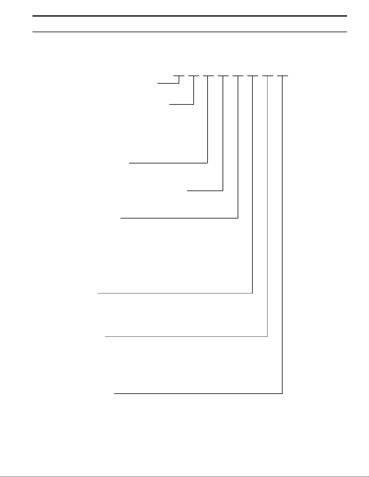
GTS PROGRAM CODE NOMENCLATURE
GTS PROGRAM CODE NOMENCLATURE
1
How many tanks are in the system
(1-6)
What type of control does the unit have
S - Single staged
E - Externally staged
Z - Zone valve
T - TP
X – Slave
M – Master
Does the unit have VAV
V - Yes
O - No
Does the unit have temperature compensation
T - Yes
O - No
Humidity sensor type
C - 0-135 OHM humidistat Electric
D - 6-9 VDC humidistat
F - 1-10 VDC humidistat
E - 4-20 mA humidistat
X - 4-20 mA transmitter
S - Slave
N - None (On/Off)
P – 0-135 OHM humidstat Pneumatic
O
O
X
7
8A
(Example)
T
Burner size
5-50 MBH
7-75 MBH
1-100 MBH
6-67.5 MBH
Burner quantity
1 - One staged
2 - Two staged
4 - Four staged
5 - One modulating
6 - Two modulating
8 - Four modulating
Water level control
D - DI with manual drain
E - DI with auto drain (end of season)
M - Probe with manual drain
A - Probe with auto drain
3
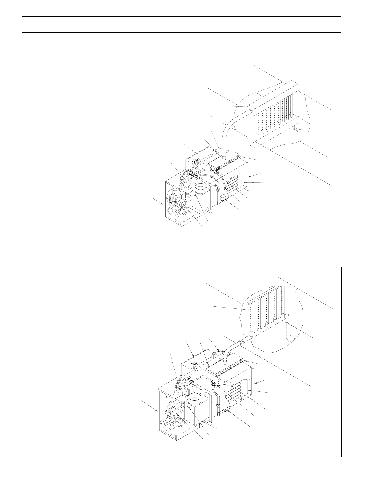
GTS Gas-to-Steam
Humidifier
This humidifier is designed to be
used with either softened or
unsoftened water. (Softening is
recommended to reduce need for
cleaning.) The probe-type level
control system requires water
conductivity of 100 micromhos/cm,
this translates to about 2 grains/gal
minimum to function, and therefore
will not operate on water treated by
reverse osmosis or deionization.
However, GTS humidifiers are
available for use with these water
types. The standard humidifier can
be converted in the field to a demineralized model. See below.
GTS® AND GTS-DI HUMIDIFIERS
®
Low-Water
Switch
Control Panel
Blower
ULTRA-SORB
Cover
Knob
Cover
Evaporating
Chamber
Heat Exchanger
GTS-DI Option
For use with deionized or reverse
osmosis water. This unit produces
chemical-free steam and reliable,
accurate humidification control. It
is virtually maintenance-free, with
no wasted water, heat, or downtime.
The DI unit uses a float valve to
control water levels.
Shroud
RAPID-SORB
Control Panel
Blower
Gas Valve
Cover
Knob
Flue Box
Blocked Vent Tap
®
Low-Water
Switch
Fill Valve
Probes
Manual or
Electric Drain Valve
Cover
Evaporating
Chamber
OM-730
Shroud
Flue Box Drain Valve
Blocked Vent Tap
Gas Valve
Heat Exchanger
Float Valve
Low-Water Cut-Out
OM-735
4

SAFETY PRECAUTIONS
WARNING:
Improper installation, adjustment, alteration, service,
maintenance, or use can cause carbon monoxide
poisoning, an explosion, fire, electrical shock, or other
conditions which may cause personal injury or property
damage. Consult a qualified installer, service agency,
local gas supplier, or your distributor or branch for
information or assistance. The qualified installer or
agency must use only factory authorized and listed kits
or accessories when modifying this product. A failure
to follow this warning can cause electrical shock, fire,
personal injury, or death.
• Inspect humidifier and accessories upon arrival for
damaged, missing, or improper parts. If there is a
problem, call DRI-STEEM.
• Application of this humidifier should have special
attention given to vent sizing and material, gas input
rate, and unit sizing. Improper installation or misapplication of the humidifier can require excessive servicing
or cause permanent component failure.
• When working on equipment, observe precautions in
this literature, tags, and labels attached to or shipped
with the unit and other safety precautions that may
apply. Wear safety glasses and work gloves. Have fire
extinguisher available during start-up, adjustment
procedures, and service calls.
• Do not use this appliance if any part has been under
water. Immediately call a qualified service technician to
inspect the appliance and to replace any part of the
control system and any gas control which has been
under water.
• Do not lift humidifier by gas controls, gas manifold,
fire box, or control shroud.
• Should overheating occur, or the gas supply fail to
shut off, shut off the manual gas valve to the appliance
before shutting off the electrical supply.
5
INSTALLATION
Precautions
• The installation must conform to the requirements of
the authority having jurisdiction or, in the absence of
such requirements, to the National Fuel Gas Code,
ANSI Z223.1 (latest edition). In Canada, the installation
of this unit must comply with local plumbing or waste
water codes and other applicable codes and with the
current code CAN/CGS-B149.1 "Installation Code for
Natural Gas Burning Appliances and Equipment" or
CAN/CGA-B149.2, "Installation Code for Propane
Burning Applications and Equipment."
• Do not install in potentially explosive or flammable
atmospheres laden with grain dust, sawdust, or similar
airborne materials.
• Installation of humidifier in high humidity or salt water
atmospheres will cause accelerated corrosion, resulting
in a reduction of the normal life-span of the unit.
• To prevent premature heat exchanger failure, do not
locate ANY gas-fired unit in areas where chlorinated,
halogenated or acid vapors are present in the atmosphere.
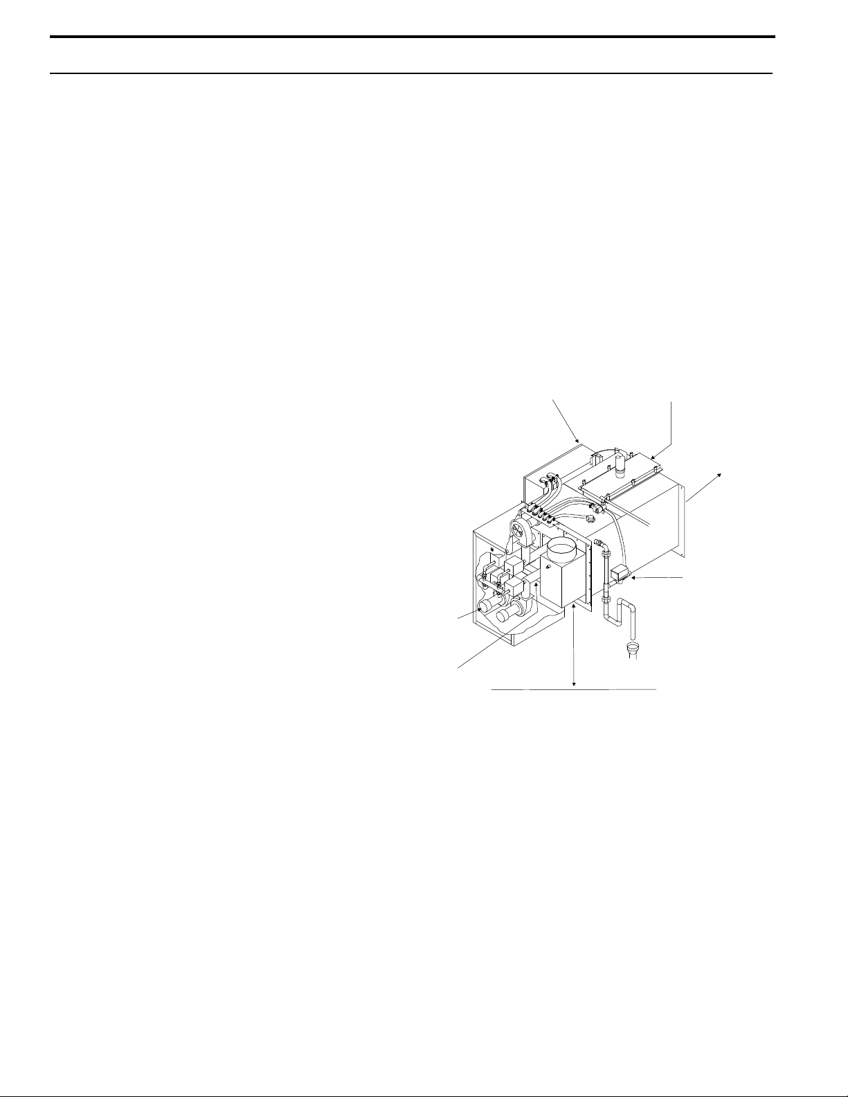
Required Clearance:
For recommended service and maintenance purposes the
following clearances should be maintained:
• Heat exchanger removal - front, 30"
• Burner shroud removal - front, 24"
• Control cabinet - left side, 36"
• Drain valve - right side, 12"
• Clean-out tray - rear, 30"
(not applicable with DI/RO systems)
• Cover removal - top, 18"
• Distance from vent box to combustible
floor - 30"
GTS clearance recommendations
Control cabinet, 36"
Cover, 18"
Cleanout tray, 30"
• Locate the humidifier in an area clear of combustible
materials, gasoline, and other flammable vapors and
liquids.
• Do not locate units in tightly sealed rooms or small
compartments without provision for adequate combustion
air and venting. Combustion air must be supplied to the
room through a minimum of two permanent openings in
the wall, at least one near the bottom. The openings
should provide one square inch of free area per 1000
BTUH input rating of the unit with a minimum of 100
square inches for each opening, whichever is greater.
See table 10-1 and information on pages 10 and 11 for
additional details.
Burner
shroud,
24"
Heat exchanger, 30"
Drain valve, 12"
30"
Floor
6

INSTALLATION
Important:
• Remove all shipping brackets and materials before
operating the humidifier.
• Humidifier flue gases must be vented to the outside
atmosphere.
• Power supply disconnect switch must be in the off
position while making wiring connections to prevent
electrical shock and equipment damage. All units must
be wired in strict accordance with wiring diagram furnished
with this unit.
• Turn off all gas while installing the run-out and manual
shut-off valve for the humidifier.
Locating the Humidifier
• Provide a level, solid foundation for the humidifier.
Locate the humidifier as near as possible to chimney or
outside wall so that the flue pipe from the humidifier is
short and direct. The location should also be such that
the gas ignition system components are protected from
water during humidifier operation and service.
Supply Water and Drain Overflow
Connections
IMPORTANT: The humidifier is shipped with the automatic drain valve locked in the manual open position.
This position reduces the possibility of damaging the
valve seat from the heat of sweating the drain connection
during installation. After the drain connection has been
completed the "manual open" lever position must be reset
to the auto position. Failure to close the drain valve will
not allow the tank to fill.
Regardless of the type of water used, the following
general instructions must be followed:
• Union connections must be made at the humidifier on
the cold water supply and drain/overflow lines.
• A shut-off valve should be provided in the supply water
line to isolate the humidifier from the water system while
servicing.
• If the water pressure is above 60 psi and/or water
hammer would be objectionable, a pressure reducing
valve or shock arrester should be installed.
• The humidifier should be installed in a location away
from drafts and properly protected. If installed in a
separate room, follow the instructions concerning
combustion and ventilation air.
• The humidifier should be located in an area where
leakage from the tank or its connections will not result
in damage to the adjacent structure or to lower floors of
the structure. When such locations cannot be avoided,
it is recommended that a suitable drain pan, adequately
drained, be installed under the humidifier. The pan must
not restrict combustion air flow.
• The humidifier must not be installed on carpeting, tile,
or other combustible material other than wood flooring
(indoor application only).
• Install humidifier so electrical components are protected from water.
• The appliance must be kept free and clear of insulating materials when located in an insulated space.
Insulating material may be combustible. Inspection of
the appliance area must be performed when the appliance is installed, or when insulation is added.
• A 3/4” opening is provided in the humidifier tank to
accommodate skim and/or overflow protection. A water
seal is required on the drain/overflow connection and a 1”
air gap should be provided prior to a building drain. (Note:
Follow local code requirements regarding size of drain
pipe.) The water seal must be piped to hold steam in the
humidifier and also provide a pressure relief if the steam
outlet becomes clogged. (See diagram on page 15)
• Insulating unions or bushings must be used to make
connections between copper and other dissimilar metal
fittings, such as galvanized steel. These insulating
fittings are required to minimize electrolytic corrosion,
which results from the direct connection of dissimilar
metals in a water system.
• Before beginning ignition sequence of the humidifier at a
new installation, be sure the humidifier tank is full of water
and the water is free to flow into the tank.
7
INSTALLATION
Drain Piping and Material
Drain piping diagrams are provided on page 15. If nonmetallic pipe or hose is used, it must be capable of
withstanding temperatures up to 212°F.
To prevent steam from escaping out the drain line, a
water seal must be provided in the drain line of sufficient
height to contain the pressure developed within the
humidifier and steam dispersion system. To determine
the proper height of the water seal, see table 15-1 on
page 15.
Make-up Water Piping and Material
Make-up water piping diagrams are provided on page 15.
Minimum make-up water pressure must be 25 psig.
When non-metallic water piping is used, it must be rated
to withstand 212°F or greater temperature. If not, the
final 3 feet connected to the humidifier should be metallic
and should not be insulated.
As part of the fill valve assembly, the needle valve
restricts the rush of cold water entering the evaporating
chamber during the fill cycle. Adjusting the supply water
flow with the needle valve will reduce fill cycle noise
from the collapsing steam head in the humidifier. Adjusting the needle valve will also reduce the drop in
output during a fill cycle. Care must be taken to not
reduce the fill rate below the humidifier's capacity, this it
will cause a low-water shutdown.
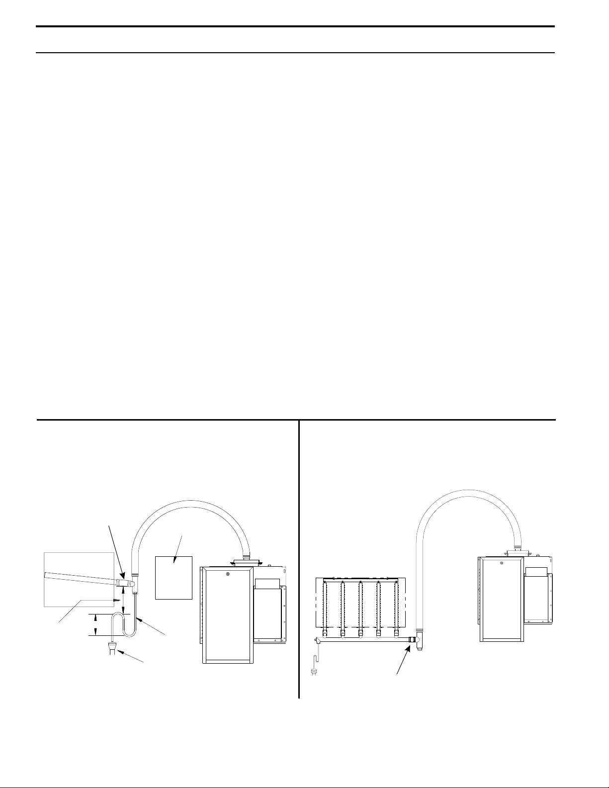
Vapor Hose Piping
When a vapor hose and stainless steel dispersion
tubes are used, they should be pitched back to the
humidifier. A minimum slope of 2" per foot (with no “low
spots”) is recommended. When this is not possible due
to duct elevation or an obstruction, alternate arrangements may be used as shown in figures 8-1 and 8-2
below.
Any condensate that forms in the vapor hose must be
removed. Preferably, it should be returned to an open
drain with a water seal of sufficient height to contain the
duct static pressure, as shown in figure 8-1.
Figure 8-1: Piping method recommended when
obstruction prevents dispersion tube from being
continuously pitched back to humidifier
Inline Tee
(1½" Dia. - Part # 162710)
(2" Dia. - Part # 162712)
Duct
5" Min.
4" Min.
Funnel or
OM-749
Notes:
• The GTS typically requires multiple dispersion tubes.
* Refer to local codes for drain pipe size requirements.
Floor Drain*
Obstruction
GTS
¾" Tubing
Figure 8-2: Piping method recommended when
humidifier must be mounted higher than the duct
Duct
GTS
Inline Tee
(1½" Dia. - Part # 162710)
(2" Dia. - Part # 162712)
OM-750
8
INSTALLATION
Gas Piping
(See "Gas Piping" diagram on page 15.)
CAUTION:
Gas pressure to humidifier controls must never
exceed 14” W.C. (1/2 psi). A 1/8" inch NPT plugged
tapping, accessible for test gauge connection, must
be installed immediately upstream of the gas supply
connection to the appliance.
• Piping installation must be in accordance with local
codes, and ANSI Z233.1, “National Fuel Gas Code,” or
CAN/CGA-B149 in Canada. Do not use flexible connectors.
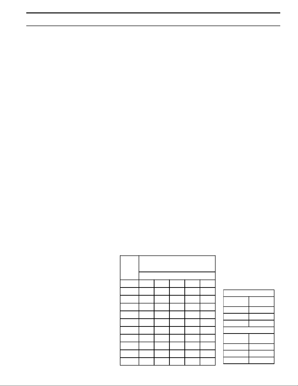
• Piping to units should conform with local and national
requirements for type and volume and gas handled, and
pressure drop allowed in the line. Refer to table 9-1 and
9-2 to determine the cubic feet per hour (cfh) for the
type of gas and size of unit to be installed. Using this
value and the length of pipe necessary, determine the
pipe diameter. Where several units are served by the
same main, the total capacity, gas flow (cfh), and length
of main must be considered. Avoid pipe sizes smaller
than 1/2”. Table 9-1 allows for the usual number of
fittings with a 0.3” W.C. pressure drop.
• After threading and reaming the ends, inspect piping
and remove loose dirt and chips.
• Support piping so that no strains are imposed on unit
or controls.
• Use two wrenches when connecting piping to unit
controls.
• Provide a drip pocket before each unit and in the line
where low spots cannot be avoided.
• Take-off to unit should come from top or
side of main to avoid trapping condensate.
• Piping subject to wide temperature
variations should be insulated.
• Pitch piping up toward unit at least
1/4” per 15’ of horizontal run.
• Compounds used on threaded joints of
gas piping must be resistant to the
harmful action of liquefied petroleum
gases.
• Purge air before lighting unit by
disconnecting piping at gas control. In
no case should line be purged into
heat exchanger.
• After installation, check field piping
and humidifier gas train for gas leaks.
Table 9-1: Gas Pipe Capacities for Gas
Pressures of .5 PSIG or Less
Length
of Pipe
Feet
1/2 3/4 1 1-1/4 1-1/2
10 132 278 520 1050 1600
20 92 190 350 730 1100
30 73 152 285 590 890
40 63 130 245 500 760
50 56 115 215 440 670
60 50 105 195 400 610
70 46 96 180 370 560
80 43 90 170 350 530
90 40 84 160 320 490
100 38 79 150 305 460
• Do not use soap solution, or open flame on humidifier
gas train. A gas leak detector is recommended.
• Install a ground joint union and a manual shut-off valve
immediately upstream of the unit including a 1/8” NPT
plugged tapping accessible for test gauge connection.
Plugged tappings for test gauges are located on all gas
valves.
• Allow at least 5 feet of piping between any high
pressure regulator and unit pipe connection.
Gas Leak Testing
• When leak testing the gas supply piping system, the
humidifier and its gas shut-off valve must be disconnected
during any pressure testing in excess of 14” W.C. (½ psi).
The humidifier must be isolated from the gas supply piping
system by closing its field-installed manual shut-off valve
during any pressure testing equal to or greater than 14"
W.C. (½ psi).
• Check gas supply pressure with all burners running at
inlet pressure tap of combination gas control. (See page
33) The recommended supply pressure should be 7"
W.C. on natural gas or 11" W.C. on LP gas. Purging of
gas piping should be performed as described in ANSI
Z223.1 (latest edition) or, in Canada, in CAN/CGA-B149
codes.
• Minimum supply pressure. Natural - 4½" W.C.
LP - 10" W.C.
• Single stage gas valves GTS™-300, 150, and 75 outlet
pressure (manifold) should be factory set at 3 1/2" w.c. for
natural, 9" w.c. for L.P. This pressure can be checked on
the combination gas valve at the out pressure tap (see
page 33).
Table 9-2: Specific
Gas Flow in Piping (Cu. Ft. per Hr.)
(At pressure drop of 0.3 in. water.
Specific gravity = 0.60)
Iron Pipe Size (NPT) Inches
Gravity Conversion
Factors
Multiplying factor to be used
with table 9-1 when the
specific gravity of gas is other
than 0.60.
Natural Gas
Specific
Gravity
0.55 1.04
0.60 1.00
0.65 0.962
Propane Gas
Specific
Gravity
1.50 0.633
1.53 0.626
1.60 0.612
Factor
Factor
9
INSTALLATION
• Two stage gas valves (used on GTS® 400, 200 and 100)
have a 10 second high fire stage and then drop to a
normal fire stage. Factory settings for natural gas are 5"
w.c. high, 3 1/2" w.c. normal. Factory settings for L.P. gas
are 8" w.c. high, 6" w.c. low. These pressures can be
checked on the combination gas valve at the out pressure
tap (see page 33).
Electrical
CAUTION:
Do not connect aluminum wire between disconnect
switch and humidifier. Use only copper wire.
WARNING:
The cabinet must have an uninterrupted or unbroken
ground according to National Electrical Code, ANSI/NFPA
70 and Canadian Electrical Code, CSA C22.1, or local
codes to minimize personal injury if an electrical fault
should occur. This may consist of electrical wire or
conduit approved for electrical ground when installed in
accordance with existing electrical codes. Do not use gas
piping as an electrical ground.
• GTS Humidifiers should be supplied with 120-volt AC,
60-Hz, 15-amp separately fused electrical service. The
GTS humidifier is equipped with a transformer to step
down the voltage to 24 VAC control voltage.
• When installed, the GTS humidifier must be electrically
grounded in accordance with local codes or, in the absence of local codes, with the National Electrical Code
ANSI/NFPA No. 70-1987. The electrical conductors shall
be Type MTW (105°C) AWG #14 wire for line voltage
(120V), with BLACK WIRE for HOT; WHITE WIRE for
NEUTRAL, GREEN WIRE for GROUND; and #18 gauge
for control wiring. All electrical components and wiring
must be protected from mechanical damage and water.
The control system requires an earth ground for proper
operation.
• The humidifier is adjusted for correct performance. Do
not alter fan or operate motors at reduced speed.
Combustion and Ventilation Air
CAUTION:
Air for combustion must not be contaminated by
halogen compounds, which include fluoride, chloride,
bromide and iodide. These elements are found in
aerosol sprays, detergents, bleaches, cleaning solvents, salts, air fresheners, and other household
products.
CAUTION:
The operation of exhaust fans, kitchen ventilation
fans, clothes dryers, or fireplaces could create a
negative pressure condition at the humidifier. Makeup air must be provided for the ventilation devices, in
addition to that required by the humidifier.
• All fuel burning equipment must be supplied with air for
combustion of the fuel. Sufficient air MUST be provided
to ensure there will not be a negative pressure in the
equipment room or space.
• Provisions for adequate combustion and ventilation air
must be provided in accordance with Section 5.3, Air for
Combustion and Ventilation, of the National Fuel Gas
Code, ANSI Z223.1-1988, or applicable provisions of the
local building codes. Canadian installations must be
installed in accordance with sections 7.2, 7.3, and 7.4 of
the CAN/CGA.B149 Installation Codes, and all authorities
having jurisdiction.
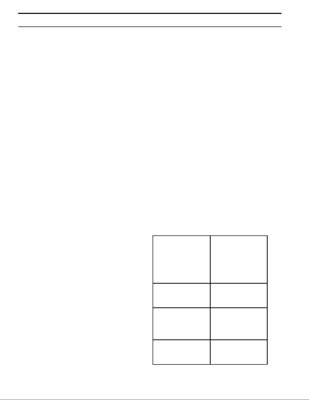
Table 10-1: Location of Humidifier and Required Air
Openings to Confined Space
Confined Space - All air
from inside the building;
conventional frame.
Brick or stone
construction with normal
infiltration. (Can only be
rarely used with larger
input units.)
Two openings, 1 square
inch per opening per
1000 BTU/hr. input.*
The minimum free area
of opening is 100 square
inches.
• The current characteristics, and capacity requirements
should be checked against the nameplates. All wiring
must be in accordance with all governing codes, and with
GTS wiring diagram located inside the control cabinet.
See table 13-1 for information on the various models.
• See page 14 for recommended knockout locations for
the electrical power supply and control wiring connections
on the control cabinet.
• See separate publication for the specific controller
furnished with this specific GTS humidifier.
10
Confined Space - All air
from outside the building
through air ducts.
Confined Space - All air
from outside the
building, through wall
openings only (no
ducts.)
Unconfined Space - All
air from outside the
building.
Two openings, 2 ducts, 1
square inch per opening
per 2000 BTU/hr. input.*
Two openings, 1 square
inch per opening per
4000 BTU/hr. input.*
Same as confined
space, all air from
outside the building.*
*Note the minimum dimension of any opening is three
inches.

INSTALLATION
• For proper and safe operation this appliance needs air
for combustion and ventilation. DO NOT block or
obstruct air openings on the appliance, spaces around the
appliance, or air openings communicating with the appliance area.
• DO NOT block the flow of combustion and ventilation
air. To provide for necessary oxygen for proper combustion, opening must be provided to allow outside air to enter
the space in which the heater is located. Enclosed
spaces, such as equipment rooms, must be vented at the
blower for combustion air. The size of air openings must
be based on all gas-burning equipment installed in the
space involved. Four types of locations, and the requirements of each, are outlined in table 10-1, on page 10.
Vertical and Horizontal Venting Guidelines
(Stack Connection)
• The GTS® is a fan assisted category 1 appliance.
• The purpose of venting the gas humidifier is to completely remove all products of combustion and ventilation
gases to the outside air, without condensation in the
stack.
• When connecting the humidifier to a gas vent or chimney, the installation shall be in accordance with Part 7,
Venting of Equipment, of the National Fuel Gas Code,
ANSI Z223.1, or Section 7, Venting Systems and Air
Supply Appliances, of the CAN/CGA B149 Installation
Codes, the local building codes, and the vent
manufacturer's instructions.
• Do not reduce the vent diameter, and avoid short turns
in the vent piping. Use the same size stack as the vent
furnished with the humidifier. Maintain a minimum
upward slope of 1/4-inch-per-linear foot on all horizontal
runs. Maintain proper support of vent connections and
joints. Observe clearances (in accordance with applicable codes) from all combustible materials, and obtain
an approved cap for the stack outlet. The bottom of the
cap must be one stack diameter above the top of the
stack.
• Inspect for proper and tight construction. Any restrictions or obstructions must be removed. An existing
chimney may require cleaning.
• Chimney or vent must extend at least 3 feet above its
passage through a roof and at least 2 feet above any ridge
within 10 feet of the chimney. (Local codes apply.)
• Minimum clearance from the vent connector to combustible material is 6 inches unless the combustible materials
are protected in accordance with applicable codes. The
recommended vent system for the GTS-400, 200 and
100 humidifiers is constructed of Type C single wall vent
pipe (UL or CUL listed). Type C vent requires varying
levels of insulation when penetrating a combustible wall
depending on vent temperatures.
• This humidifier must not be connected to a chimney flue
servicing a separate appliance designed to burn solid
fuel.
• Never connect this humidifier to a chimney serving a
fireplace, unless the fireplace opening is permanently
sealed off.
• The recommended vent system for the GTS-300, 150,
and 75 humidifier is constructed of Type B double-wall
vent pipe (UL or CUL listed). Type B vent is rated for
400°F plus ambient temperature. A minimum 1-inch
clearance is required between Type B vent and combustible materials. Field expertise has shown that venting
through a properly sized Type B vent significantly
reduces the occurrence of vent condensation.
• It may be necessary to add insulation to Type B doublewall vent and to single-wall vent connector, if allowed by
local codes, in some applications. When insulation is
required, it must be at least 1-inch thick fiberglass with foil
backing. Using permanent foil tape, attach insulation to
vent pipe. Both the foil tape and fiberglass insulation
must be suitable for temperatures up to 450°F.
• Insulation must be added to any vent connector which
will be exposed to ambient temperatures of 30°F or less,
especially any application using single-wall vent pipe as a
connector.
• Do not insulate vent pipe exposed to outdoor weather
conditions (i.e. above roof lines).
• Venting into an unlined masonry or concrete chimney is
prohibited by code.
• If this humidifier is connected to a lined, masonry
chimney, the chimney must be sized and installed according to the provisions of the National Fuel Gas Code, or
Canadian CAN/CGA.B149 requirements. Vent connectors
from the humidifier to the chimney should be made with
insulated Type C single-wall vent pipe or Type B vent
pipe for GTS-300, 150, and 75. The GTS-400, 200 and
100 is approved for single wall vent only.
• Installation of the vent pipe should be as directly as
possible, with a minimum number of turns or elbows.
• Rigidly support the vent pipe every 5 feet or less with
hangers or straps to ensure that there will be no movement after installation. The humidifier vent box should not
be supporting the weight of the vent piping.
11
 Loading...