

DriSteem GTS04 User Manual
DRISTEEM GTS® HUMIDIFIFIER, STANDARD WATER
Water Treatment Systems
Service Kit Manual
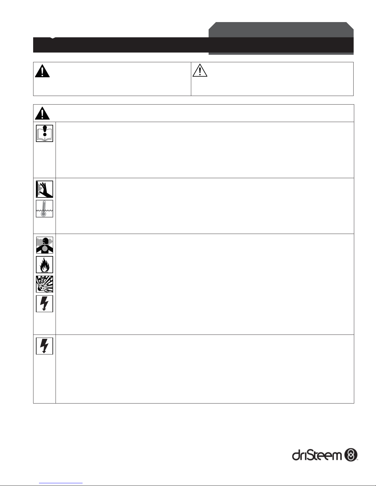
WARNING
Indicates a hazardous situation that could result in death or
serious injury if instructions are not followed.
mc_051508_1145
WARNING
Read all warnings and instructions
This page provides important safety instructions; it is intended to supplement — not replace — the humidifi er's Installation,
Operation, and Maintenance Manual (IOM). Read the IOM that was provided with the humidifi er before performing
service or maintenance procedures on any part of the system. Failure to follow all warnings and instructions could
produce the hazardous situations described here and in the IOM, resulting in property damage, personal injury, or
death.
If the IOM is missing, go to www.dristeem.com to download a replacement.
Hot surfaces and hot water
Steam humidifi cation systems have extremely hot surfaces, and water in tanks, electrode cylinders, steam pipes, and
dispersion assemblies can be as hot as 212 °F (100 °C). To avoid severe burns, allow the entire humidifi cation system to
cool.
Follow the cool-down procedure in the humidifi er's IOM before performing service or maintenance procedures on any
part of the system.
Carbon monoxide, fi re, explosion, and electrical shock hazards
Improper installation, adjustment, alteration, service, maintenance, or use can cause carbon monoxide poisoning, fi re,
explosion, electrical shock, and other hazardous conditions. These hazardous conditions could cause personal injury,
property damage, or death. To prevent hazardous conditions, read all warnings; lock all power disconnect switches in
the OFF position before removing any access panels; and consult a qualifi ed installer, service agency, local gas supplier,
or your distributor or branch for information or assistance. The qualifi ed installer or agency must use only factory
authorized and listed kits or accessories when modifying this product.
If you smell gas:
• Do not try to light any appliance.
• Do not touch any electrical switch; do not use any phone in your building.
• Immediately call your gas supplier from an off-site phone. Follow the gas supplier’s instructions.
• If you cannot reach your gas supplier, call the fi re department.
Electrical shock hazard
If the humidifi er starts up at a call for humidity during maintenance, severe bodily injury or death from electrical shock
could occur. To prevent such start-up, follow the procedure below before performing service or maintenance procedures
on this humidifi er (after the tank has cooled down and drained):
1. Use the Vapor-logic
2. Shut off all electrical power to the humidifi er using the fi eld-installed fused disconnect, and lock all power disconnect
switches in the OFF position.
3. Close the fi eld-installed manual water supply and gas shut-off valves.
®
keypad to change the control mode to Standby.
CAUTION
Indicates a hazardous situation that could result in damage to
or destruction of property if instructions are not followed.
Parts in this service kit are for the GTS04 humidifi er (October 2004 to present). Parts are listed on page 2.
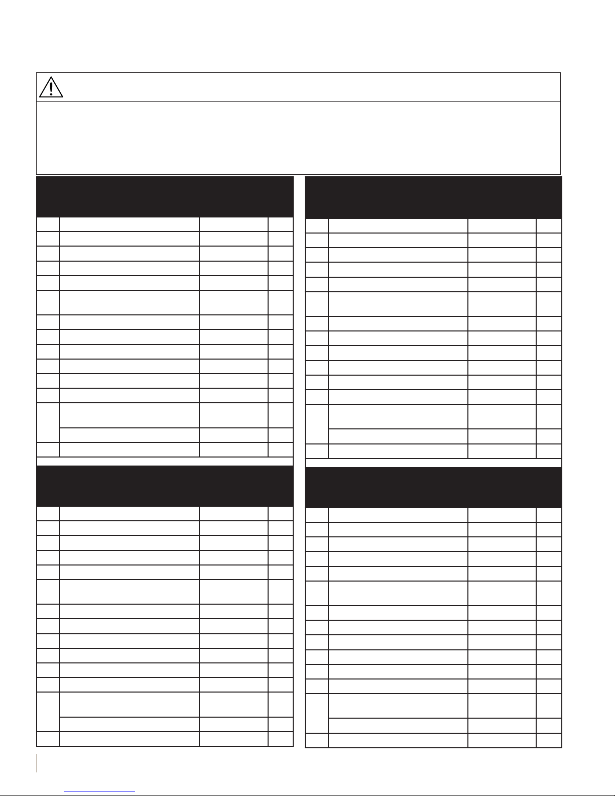
GTS, standard water, service kit parts
CAUTION
Damage from hot discharge water
Discharge water can be as hot as 212 °F (100 °C) and can damage the drain plumbing.
If the humidifi er is equipped with a water tempering device such as a DriSteem Drane-kooler
to function properly. Make sure the water supply to the Drane-kooler remains open during draining.
If the humidifi er is not equipped with a water tempering device, allow the tank to cool before opening the drain valve.
™
, it needs fresh make-up water in order
GTS04, standard water, 1 burner
Service Kit No. 900100-401 (North America)
Service Kit No. 901100-401 (Europe)
No. Part Description Part No. Qty.
1 Probe tool (see Probe Tool inset) 406201 1
2 Probe assembly 406303-010 1
3 Probe gasket 309750-004 1
4 Silicone, clear (not shown) 320000 1
5 Silicone, high-temperature (not
shown)
6 Sediment screen (see Fill Valve inset) 300051 1
7 Probe plate gasket 308235-006 1
8 Cleanout plate gasket 308235-005 1
9 Nut, 1/4-20 w/ Nylon insert 700300-016 50
10 Burner gasket 308230-006 1
11 Blower gasket 308230-007 1
Ignitor assembly - 120V (North
America)
12
Ignitor assembly - 24V (Europe) 405718-001 1
13 Flame sensor 405725 1
320001 1
405718 1
GTS04, standard water, 2 burner
Service Kit No. 900100-402 (North America)
Service Kit No. 901100-402 (Europe)
No. Part Description Part No. Qty.
1 Probe tool (see Probe Tool inset) 406201 1
2 Probe assembly 406303-010 1
3 Probe gasket 309750-004 1
4 Silicone, clear (not shown) 320000 1
5 Silicone, high-temperature (not
shown)
6 Sediment screen (see Fill Valve inset) 300051 1
7 Probe plate gasket 308235-006 1
8 Cleanout plate gasket 308235-005 1
9 Nut, 1/4-20 w/ Nylon insert 700300-016 56
10 Burner gasket 308230-006 2
11 Blower gasket 308230-007 2
Ignitor assembly - 120V (North
America)
12
Ignitor assembly - 24V (Europe) 405718-001 2
13 Flame sensor 405725 2
320001 1
405718 2
GTS04, standard water, 3 burner
Service Kit No. 900100-403 (North America)
Service Kit No. 901100-403 (Europe)
No. Part Description Part No. Qty.
1 Probe tool (see Probe Tool inset) 406201 1
2 Probe assembly 406303-010 1
3 Probe gasket 309750-004 1
4 Silicone, clear (not shown) 320000 1
5 Silicone, high-temperature (not
shown)
6 Sediment screen (see Fill Valve inset) 300051 1
7 Probe plate gasket 308235-006 1
8 Cleanout plate gasket 308235-005 1
9 Nut, 1/4-20 w/ Nylon insert 700300-016 66
10 Burner gasket 308230-006 3
11 Blower gasket 308230-007 3
Ignitor assembly - 120V (North
America)
12
Ignitor assembly - 24V (Europe) 405718-001 3
13 Flame sensor 405725 3
320001 1
405718 3
GTS04, standard water, 4 burner
Service Kit No. 900100-404 (North America)
Service Kit No. 901100-404 (Europe)
No. Part Description Part No. Qty.
1 Probe tool (see Probe Tool inset) 406201 1
2 Probe assembly 406303-010 1
3 Probe gasket 309750-004 1
4 Silicone, clear (not shown) 320000 1
5 Silicone, high-temperature (not
shown)
6 Sediment screen (see Fill Valve inset) 300051 1
7 Probe plate gasket 308235-006 1
8 Cleanout plate gasket 308235-005 1
9 Nut, 1/4-20 w/ Nylon insert 700300-016 72
10 Burner gasket 308230-006 4
11 Blower gasket 308230-007 4
Ignitor assembly - 120V (North
America)
12
Ignitor assembly - 24V (Europe) 405718-001 4
13 Flame sensor 405725 4
320001 1
405718 4
GTS DRISTEEM STANDARD SERVICE MANUAL
2
This service kit contains the replacement parts called
out in the parts drawing to keep your DriSteem
humidifi er operating at peak performance. This
Service Kit Manual provides important safety and
service instructions; it is intended to supplement — not
replace — the humidifi er's Installation, Operation,
and Maintenance Manual. Please see Read all
warnings and instructions on page 1.
While performing service and maintenance
procedures, replace existing parts with the new parts
provided in the service kit.
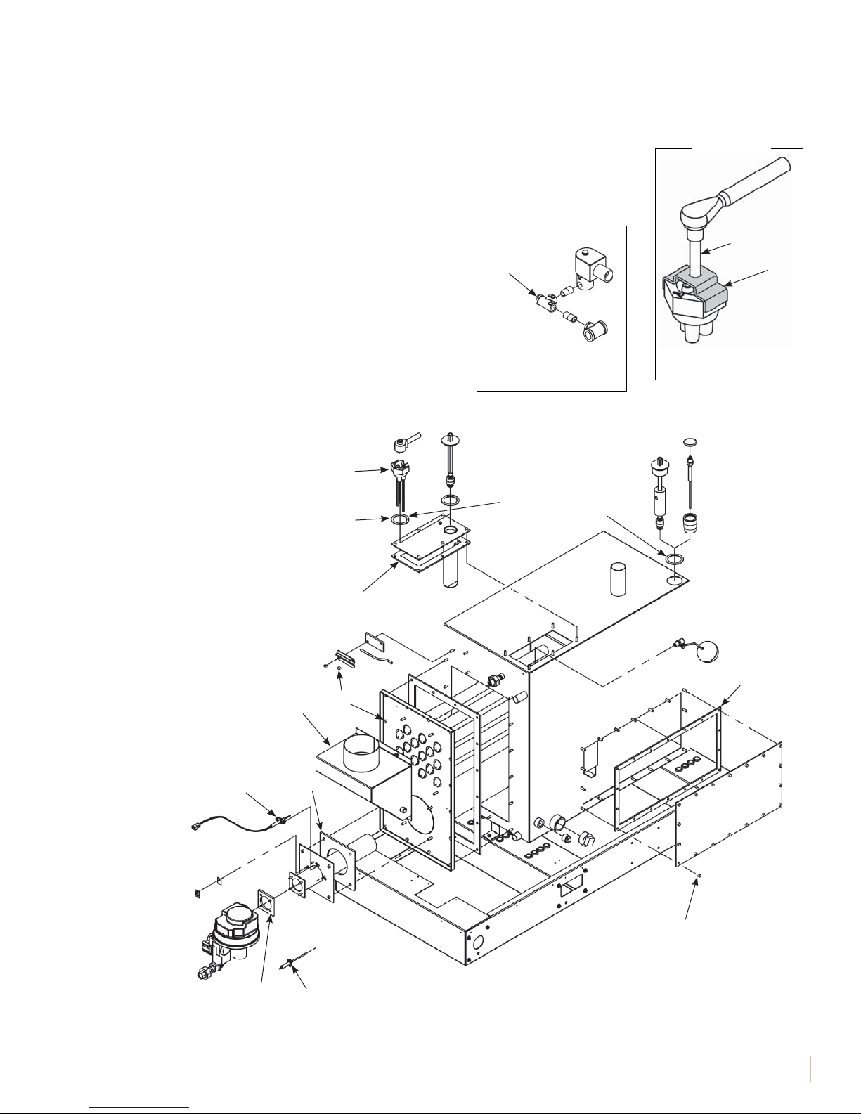
2
Notes:
• Parts for both standard water and DI
water humidifi ers are shown.
• Components may by oriented
differently than shown in drawing.
3
GTS, standard water, service kit parts
Probe Tool
Fill Valve
6
Sediment screen (6)
inside of Tee
OM-1244X
Apply clear silicone
(4) to both sides of
gaskets.
Torque probe assembly
to 10 ft-lbs (13.6 N-m).
mc_051508_1320
3/8" drive
1
OM-7395X
Flue box
If removed, clean off and replace
high-temperature silicone (5)
along mating surfaces.
12
11
7
8
9
10
9
Torque to 25 to 35 in-lbs
(2.8 to 4.0 N-m).
OM-1243X
13
GTS DRISTEEM STANDARD SERVICE MANUAL
3

GTS, standard water, service instructions
INSPECTION RECOMMENDATIONS:
• User inspection every 30 days.
• Appliance system inspected once a year by a qualifi ed
service person.
Note: Do the procedure below prior to cool-down/
shut-down.
DURING INSPECTION, VERIFY THE FOLLOWING:
• Proper fi eld operation of burner. Measure CO,
CO2%, O2%, fl ue temperature, and burner effi ciency
at 100% demand with the tank at a boil. Verify that
measurements are within the guidelines described in
Table 4-1; if not, consult DriSteem.
Table 4-1:
GTS products of combustion guidelines
(at 100% demand)
CO
CO2 %
O2 % 4-7%
Flue temperature
Burner effi ciency Greater than 80%
Less than 40 ppm; 0 or low single digits is
typical
8-10%; 9% is typical for natural gas, 10% is
typical for LP gas
Less than 400 °F plus room temp.
(Less than 204.4 °C plus room temp.)
• Flue passageways external to the appliance, such as
vent connector and chimney, are clear and free of
obstructions.
• Vent connector is in place, sloping upward and is
physically sound without holes or excessive corrosion.
• Physical support of the appliance is sound without
sagging, cracks, or gaps between fl oor legs or tank
fl anges.
• There are no obvious signs of deterioration of the
appliance.
• Burner fl ame is blue or orange in color — up to ¼"
(6 mm) from the surface of the burner.
Before performing service or maintenance procedures,
allow the tank to cool down. Insulated and uninsulated
tanks will have hot surfaces.
Note: Fresh make-up water is used to speed up cooling.
1. Verify that there is no call for humidity and that the
aquastat set point (adjusted using the keypad/display
Setup screens) is less than room temperature (default
setting is 40 °F [4 °C]) so the burners do not energize
while cooling down the tank.
2. Verify that the tank is in Auto mode so it will fill after
draining begins.
3. Drain the tank:
Models with a manually operated drain valve:
a. Manually open the drain valve by moving the valve
b. Let the fi ll water run until the tank is cooled; then
c. Let the tank drain; then manually close the drain
For models without a manually operated drain
a. From the Main menu, enter the following submenu:
b. Change mode to Manual Drain (Vapor-logic3)
c. Change the mode back to Auto; the fi ll valve opens
d. When the fi ll valve closes, go back into Drain
e. For more information about using the keypad,
Cool down humidifier
Do not close the manual water supply before
cooling down the humidifi er; otherwise the tank
could stay hot for several hours.
lever located on the back of the drain valve to the
manual open position. The fi ll valve will open after
enough water has drained out of the tank.
shut off the fi eld-installed manual supply water shutoff valve.
valve.
valve, use the keypad to perform the cool down
procedure:
• Vapor-logic3 controller: Control Modes
• Vapor-logic4, 5, 6 controller: Tank Status.
or Drain (Vapor-logic4, 5, or 6), and allow
approximately half the water to drain out of the
tank.
and the humidifi er cools down.
mode, and allow the tank to drain completely. The
humidifi er should be cool enough to work on.
see the Vapor-logic Controller Installation and
Operation Manual shipped with the humidifi er.
GTS DRISTEEM STANDARD SERVICE MANUAL
4

GTS, standard water, service instructions
Shut down humidifier
Follow the procedure below before performing service or
maintenance procedures (after the tank has cooled down
and drained):
1. Use the controller keypad to change the control mode
to Standby.
2. Shut off all electrical power to the humidifier using the
field-installed fused disconnect, and lock all power
disconnect switches in the OFF position.
3. Close the field-installed manual water supply and gas
shut-off valves.
INSPECTION AND MAINTENANCE
Annually (also recommended when maintenance is
performed)
1. All safety devices in the control circuit should be
cycled on and off to verify they are functioning. These
include:
• High limit switch
• Airfl ow proving switch
• Low water level probe. Pull out probe plug; fi ll valve
should energize.
• Redundant low water level probe
2. Inspect tank, piping, and gaskets for water and gas
leaks.
Seasonally (or as required, depending on water quality)
1. Clean the tank:
a. Remove cleanout plate and dispose of any loose
scale that has collected in the tank. Do this before
the scale buildup reaches the bottom of the heat
exchanger.
b. Inspect the area inside the tank in front of the drain
valve fi tting and thoroughly clean all scale and
mineral buildup from that area.
2. Dismantle and clean the drain valve and associated
piping.
3. Clean the probes:
Access the probe assembly either from the electrical
panel or by removing the roof panel above the
electrical area.
a. Disconnect the probe plug and cable assembly and
unscrew the probe rod assembly from the humidifi er
probe housing.
b. Inspect the probe housing and clean, ensuring that
all the housing passageways are clear. Remove the
housing from the tank by removing the cover plate
from the tank.
• The scale should fl ake off easily from the probe
assembly rods.
• The bottom 3/8" (10 mm) of each rod is the
sensing portion; clean these areas with a wire
brush, abrasive pad, or steel wool.
c. Inspect the composite plastic probe rod assembly
for any signs of cracking, roughness, or
deterioration. If found, replace probe assembly.
d. Reassemble the probe assembly.
4. Clean the skim/overflow port:
a. Water should drain from the skimmer drain pipe
after each fi ll cycle. This should be verifi ed visually
by a weekly inspection.
b. Loosen deposits in and around the skimmer/
overfl ow port with a long tool such as a
screwdriver.
c. If fl ow through the water seal/P-trap is diminished
due to mineral accumulation:
• Remove the water seal piping from the
humidifi er and fl ush out.
• Replace the water seal with new piping if the
minerals have hardened in the water seal.
5. Clean the low water cutout probe: Remove the
shroud cover and inspect the probe rod for mineral
accumulation. The rod is located on the top of the tank
near the back. Use stainless steel wool to clean the
probe.
6. Inspect the blower motor: A lubrication port is not
provided, therefore lubrication is not required.
7. Remove dust: Using a vacuum, remove all dust from
areas around the motor, vent fan(s), and louvers that
allow air to the shrouded area.
8. When the maintenance requirements are complete:
a. Replace cleanout plate and tighten the nuts on
the plate. Torque the nuts to 25 to 35 in-lbs
(2.8 to 4.0 N-m).
b. Verify that the probe rod holder is secure and
that the probe plug and cable assembly are
plugged into the probe rod holder.
c. Verify that the drain valve assembly is in the
closed position.
d. Replace and secure all covers and doors.
e. Turn on the water supply.
f. Turn on the electrical power.
g. Turn on the gas.
Do not leave humidifi er unattended. Allow the
humidifi er to cycle through multiple fi ll cycles
and verify that the humidifi er cover, cleanout
plate, and probe holder gasket are not leaking.
Off-season maintenance
1. Perform complete inspection and cleaning of the
following:
• Probe rods
• Skimmer port and water seal
• Humidifi er tank
• Heat exchanger
2. After cleaning, the humidifier should remain empty
until humidification is required.
GTS DRISTEEM STANDARD SERVICE MANUAL
5

GTS, standard water, service instructions
Humidifier De-scaling Solution
Scale buildup on humidifi er heat exchangers
acts as an insulator, reducing humidifi er
performance while increasing energy costs.
To keep humidifi ers operating as effi ciently
as possible, remove scale with DriSteem's
Humidifi er De-scaling Solution, available for
purchase from your DriSteem representative or
distributor.
The De-scaling Solution cleans without risk
of corroding humidifi er tanks or welds. The
De-scaling Solution also cleans surfaces
unreachable by hand scraping.
DriSteem's Humidifi er De-scaling Solution is the
only approved cleaner/de-scaler for use with
DriSteem humidifi ers. Use of other cleaners/descalers may void your DriSteem warranty.
INSPECTING BURNER ASSEMBLIES AND HEAT EXCHANGER TUBES
This is not a regular maintenance item, but if the heat exchanger tubes contain
carbon deposits, soot, or other residue, clean as follows:
1. Turn off gas, electrical power, and water supply.
2. Remove gas train shroud.
3. Disconnect wiring to blowers, flame sensors, gas valves, and ignition
controllers and remove burner assemblies (each assembly is mounted with
four bolts).
4. Remove vent box.
5. Use a 6" (150 mm) flue brush with a 24" (600 mm) extension and
reversible drill. Work brush in and out of all combustion chambers.
Note: Disconnecting components from one burner assembly at a time and
then cleaning the corresponding combustion chamber and burner will
ease reassembly.
6. Remove loose deposits and residue that falls into rear header with a
vacuum cleaner and hose extension.
7. Inspect 1½" (DN40) return tubes and clean if necessary.
8. Run thin brush between turbulator and tube wall on all four sides.
9. Reinstall burner assemblies and gaskets; vent box and gasket; all electrical
wiring; gas train shroud; and pressure switch connections.
BURNER MAINTENANCE
Under normal use conditions, the burner(s) should not need cleaning for a
minimum of fi ve years. However, depending on the operating environment,
the burner(s) may require periodic cleaning to remove accumulated materials.
Failure to clean burners can result in reduced unit capacity. Use sealed
combustion in dirty environments. See burner maintenance instructions below.
DRI-STEEM Corporation
An ISO 9001: 2000 certifi ed corporation
U.S. Headquarters:
14949 Technology Drive
Eden Prairie, MN 55344
800-328-4447 or 952-949-2415
952-229-3200 (fax)
European offi ce:
Marc Briers
Grote Hellekensstraat 54 b
B-3520 Zonhoven
Belgium
+3211823595 (voice)
+3211817948 (fax)
E-mail: marc.briers@dristeem.com
Continuous product improvement is a policy
of DRI-STEEM Corporation; therefore, product
features and specifi cations are subject to
change without notice.
DRI-STEEM, GTS, and Vapor-logic are
registered trademarks of DRI-STEEM
Corporation and are fi led for trademark
registration in Canada and the European
community.
Drane-kooler is a trademark of DRI-STEEM
Corporation.
© 2015 DRI-STEEM Corporation
Form No. GTS-standard-Service_Kit_Manual_0715
Part No. 891000-101 Rev D
BURNER MAINTENANCE INSTRUCTIONS
To service the burner system, clean both the blower and the burner. Remove the
blower(s) from the system and clean dust from the wheel. Remove the burner(s)
for cleaning. Removing and cleaning one burner at a time eases reassembly.
To dislodge particulate matter from the burner surface matrix, use compressed
air (100 psig [700 kPa] maximum). Keep the air nozzle about 2" (50 mm)
from the burner’s surface, blowing air perpendicular to the burner surface
while moving the nozzle back and forth lengthwise. This dislodges particles
trapped in the matrix, pushing them back inside the burner. Avoid blowing
air across the surface, which tends to have a destructive effect on the burner
surface. Allow particulate matter to fall from the burner through the air/gas
inlet. To assist in removing the particulate matter, use a vacuum at the burner’s
air/gas inlet.
START-UP
Perform the Annual safety checks in the Inspection and maintenance section on
page 4.
If resuming operation after service, do not leave the humidifi er unattended;
allow it to cycle through multiple fi ll cycles to verify that all serviced parts
are functioning properly. See the humidifi er's Installation, Operation, and
Maintenance manual for start-up details.
DriSteem products are warranted according to the terms and conditions of
the standard two-year Limited Warranty effective when the humidifi er was
purchased. See the literature that was shipped with the humidifi er for warranty
information.
 Loading...