

Page 1
READ AND SAVE THESE INSTRUCTIONS
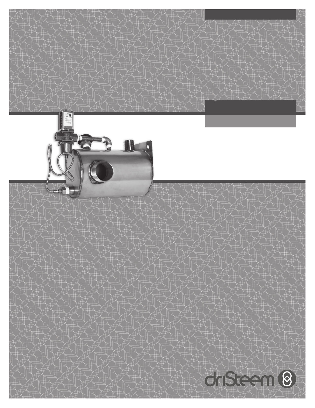
DRANE-KOOLER™
Water Tempering Device
Installation, Operation,
and Maintenance Manual
Page 2
Table of Contents
Overview
Features Summary ......................................1
Capacities and connection sizes ............................2
Dimensions ...........................................3
Installation
Installation instructions ...................................4
Mounting ............................................5
Piping ..............................................6
Operation
Start-up and operating instructions ...........................7
Maintenance/Troubleshooting
Maintenance and troubleshooting ...........................8
Replacement parts
Replacement parts ......................................9
Warranty .......................................Back cover
ATTENTION INSTALLER
Read this manual before installing.
Leave manual with product owner.
DriSteem® Corporation Technical Support
North America: 800-328-4447
Europe: +3211823595
Call us at 800-328-4447
Obtaining documents from our web site or
from DriCalc is the quickest way to view
our literature, or we will be happy to mail
literature to you.
Download DriSteem literature
Most DriSteem product manuals
are available on our website:
www.dristeem.com
INSTALLATION AND
MAINTENANCE WARNINGS
Attention installer
For warnings and cautions to the
Drane-Kooler water tempering device,
refer to the Installation, Operation,
and Maintenance Manual provided
with the humidifier.
DRISTEEM DRANE-KOOLER WATER TEMPERING DEVICE INSTALLATION, OPERATION, AND MAINTENANCE MANUAL
ii
Page 3
Features summary
OVERVIEW
COOL DISCHARGED HOT WATER
Drane-kooler is a water tempering device that mixes cold water
with hot water discharged from various types of equipment, such
as a humidifier, to reduce the discharged water temperature
before it enters a municipal sewer system.
There are two reasons to use a water tempering device. First,
most municipalities prohibit draining water hotter than 140 °F (60
°C) into their sewer systems. And second, PVC drain pipes are
susceptible to damage from water that is too hot. When faced
with either of these situations, Drane-kooler is the solution!
HORIZONTAL DESIGN
A space-efficient horizontal orientation and side drain outlet
provide enough clearance to allow the Drane-kooler to be
mounted directly underneath DRI-STEEM humidifiers, saving
footprint space while allowing room for pitched drain piping.
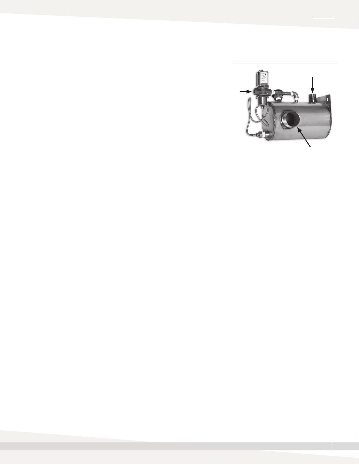
HOW IT WORKS: HOT + COLD = TEMPERED!
1. Hot water discharged from a humidifier or other appliance
enters the Drane-kooler through piping connected to the top
threaded connection. A vacuum breaker prevents backflow
into potable water systems.
2. Cold water enters through the temperature-actuated valve.
The valve and the Drane-kooler's straightforward design
ensure efficient mixing of hot and cold water. The valve's
sensor, located near the outlet, ensures that water leaving the
Drane-kooler is 140 °F (60 °C) or less before entering the
municipal sewer system.
3. Tempered water at 140 °F (60 °C) or less exits through the
side outlet for safe discharge into a municipal sewer system
or PVC pipe.
FIGURE 1-1: DRANE-KOOLER
1
2
3
RELIABLE, NON-ELECTRIC VALVE
The temperature-actuated valve is time-tested to be reliable and
maintenance-free. And because it is non-electric, no wiring is
required.
MULTIPLE MOUNTING OPTIONS
The Drane-kooler can be mounted by attaching the integral
mounting plate to a wall, by attaching the mounting plate to an
adjustable floor stand, or by using an assembly for suspension
mounting. These multiple mounting options provide capability
for the Drane-kooler to be properly supported and not secured
entirely by piping.
DRISTEEM DRANE-KOOLER WATER TEMPERING DEVICE INSTALLATION, OPERATION, AND MAINTENANCE MANUAL
1
Page 4
OVERVIEW
Capacities and connection sizes
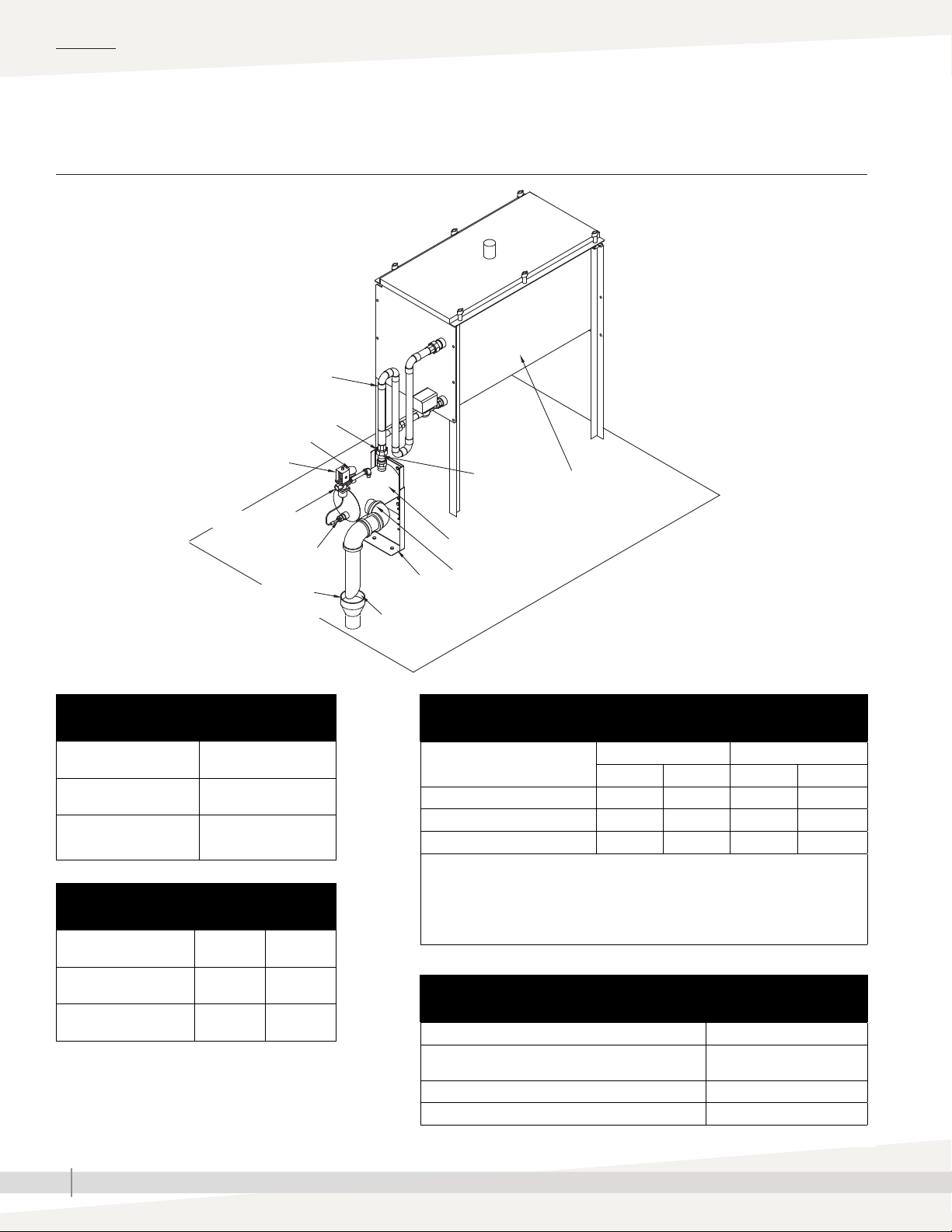
FIGURE 2-1: OPTIONAL FLOOR MOUNT PIPING EXAMPLE
Alternate water seal shown (by installer)
Service union
Vacuum breaker
Temperature-actuated valve
Hot water
enters here
Evaporative Humidifier
Cold water enters here
Temperature
sensor
Floor drain to
municipal system
*316 stainless steel optional
Table 2-1:
Drane-kooler connections
Hot water inlet connection 1" (DN25) pipe thread
Tempered water outlet
connection
Cold water supply
connection
2" (DN50) pipe thread
3/8" (DN10) pipe thread
Table 2-2:
Drane-kooler weights
lbs Kg
Adjustable
floor stand
1" air gap
(25 mm)
Drane-kooler 304 stainless steel
mixing chamber*
Tempered water
discharged here
OM-1117a
Table 2-3:
Drane-kooler capacities*
Maximum flow rate Maximum temperature
U.S. gpm L/m °F °C
Hot water inflow 6 22.7 212 100
Cold water inflow** 6 22.7 70 21
Tempered water outflow 12 45.4 140 60
Note:
* This table applies only if one humidifier is connected to one Drane-kooler,
with no more than 10' (3m) of vertical dimension between the Drane-kooler
and the humidifier.
** Cold water inflow pressure must be between 25 psi and 80 psi (172 kPa and 552 kPa).
Shipping weight 9.5 4.3
Operating weight 15 6.8
DRISTEEM DRANE-KOOLER WATER TEMPERING DEVICE INSTALLATION, OPERATION, AND MAINTENANCE MANUAL
2
Table 2-4:
Drane-kooler material
Description Material
Drane-kooler body
Optional material
Valve body Bronze
Vaccuum breaker Brass
304 stainless steel
316 stainless steel
Page 5
Dimensions
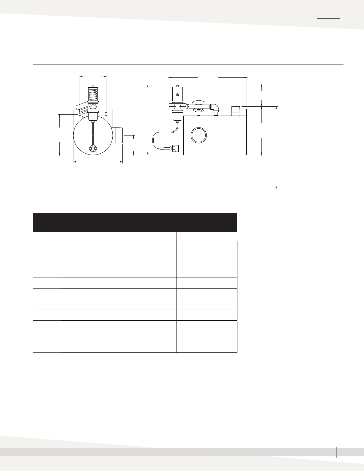
FIGURE 3-1: DRANE-KOOLER DIMENSIONS
OVERVIEW
Side Elevation Front Elevation
E
H
C
F
G
Table 3-1:
Drane-kooler dimensions
Item Description Inches (mm)
Height with floor stand
(from floor to top of hot water inlet in 1" [25 mm] increments)
A
Height with floor stand and extension
(from floor to top of hot water inlet in 1" [25 mm] increments)
B Height from bottom of tank to top of hot water inlet 7.5 (191)
8.25 to 12.25 (210 to 312)
13.25 to 20.25 (337 to 515)
J
D
B
A
Floor
OM-1113
C Height from bottom of tank to top of valve 10.5 (268)
D Height from top of hot water inlet to top of valve 3.0 (76)
E Height from bottom of tank to center of mounting hole 6.25 (159)
F Height from bottom of tank to center of tempered water outlet 3.0 (76)
G Width of tank and tempered water outlet 7.5 (191)
H Width of mounting plate holes, center to center 4.0 (102)
J Length, from valve inlet to mounting plate 12.0 (305)
DRISTEEM DRANE-KOOLER WATER TEMPERING DEVICE INSTALLATION, OPERATION, AND MAINTENANCE MANUAL
3
Page 6

INSTALLATION
Installation locations
STEP-BY-STEP INSTALLATION INSTRUCTIONS
1. Verify that maximum flow of hot water into the Drane-kooler does not exceed 6 U.S. gallons
per minute (gpm) (22.7 L/m).
2. Note that there are three connections to be made to the
Drane-kooler:
• Cold water supply
• Hot water inlet (from a humidifier or other appliance)
• Tempered water piping to drain
3. Position the Drane-kooler to allow the most direct path of piping to minimize fittings (see the
piping diagrams on Pages 8-9).
4. Position unions on all connections as close to the Drane-kooler as possible to make cleaning
and maintenance easier.
5. Cold water supply connection instructions:
• Cold water supply connection on valve is 3/8" (DN10) pipe thread.
• Pipe a 3/8" (DN10) line directly to the Drane-kooler from the main water supply line.
To ensure adequate water pressure to the Drane-kooler, do not connect to
a supply water line that is dedicated to other appliances.
If installing the Drane-kooler with a humidifier, do not branch off the 1/4" (DN8) cold
water supply line to the humidifier.
• Verify that the supply water pressure to the valve is at least 25 psi (172 kPa) and not more
than 80 psi (552 kPa).
• Install a cold water supply union as close to the
Drane-kooler as possible.
• Install a cold water shut-off valve before the union in the cold water supply line.
6. Hot water inlet connection instructions:
• Hot water inlet connection is 1" (DN25) pipe thread.
• Locate a union as close to the Drane-kooler as possible
• Run 1" (DN25) pipe as directly as possible from the hot water appliance (humidifier) to the
Drane-kooler. If the piping to the hot water inlet has a horizontal run, maintain a pitch to
the Drane-kooler of at least 1/8"/ft (1%).
7. Tempered water (to drain) connection instructions:
• Tempered water outlet connection is 2” (DN50) pipe thread.
• Install a union as close to the Drane-kooler as possible.
• Run a 2” (DN50) pipe as directly as possible from the Drane-kooler to the drain. Maintain
a pitch to drain of at least 1/8”/ft (1%).
• Make sure there is a 1” (25 mm) air gap between the drain piping and the drain.
DRISTEEM DRANE-KOOLER WATER TEMPERING DEVICE INSTALLATION, OPERATION, AND MAINTENANCE MANUAL
4
Page 7
Mounting
INSTALLATION
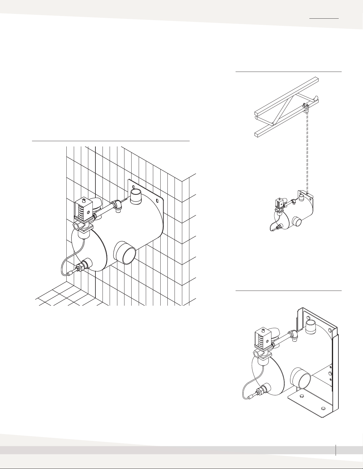
THREE MOUNTING OPTIONS
Use one of the mounting options shown on this page to
ensure that the Drane-kooler will be properly supported and
not secured entirely by piping. Floor stand and suspension
mount hanger assembly are ordered separately.
FIGURE 5-1: STANDARD WALL MOUNT
FIGURE 5-2: OPTIONAL SUSPENSION
MOUNT
OM-1116
Note:
* The optional suspension mount hanger assembly
includes an L-bracket, two nuts, and two bolts that
attach to the Drane-kooler. Beam clamp assembly and
1/4" threaded rod are supplied by others.
FIGURE 5-3: OPTIONAL FLOOR MOUNT
OM-1114
OM-1115
DRISTEEM DRANE-KOOLER WATER TEMPERING DEVICE INSTALLATION, OPERATION, AND MAINTENANCE MANUAL
5
Page 8
INSTALLATION
Piping
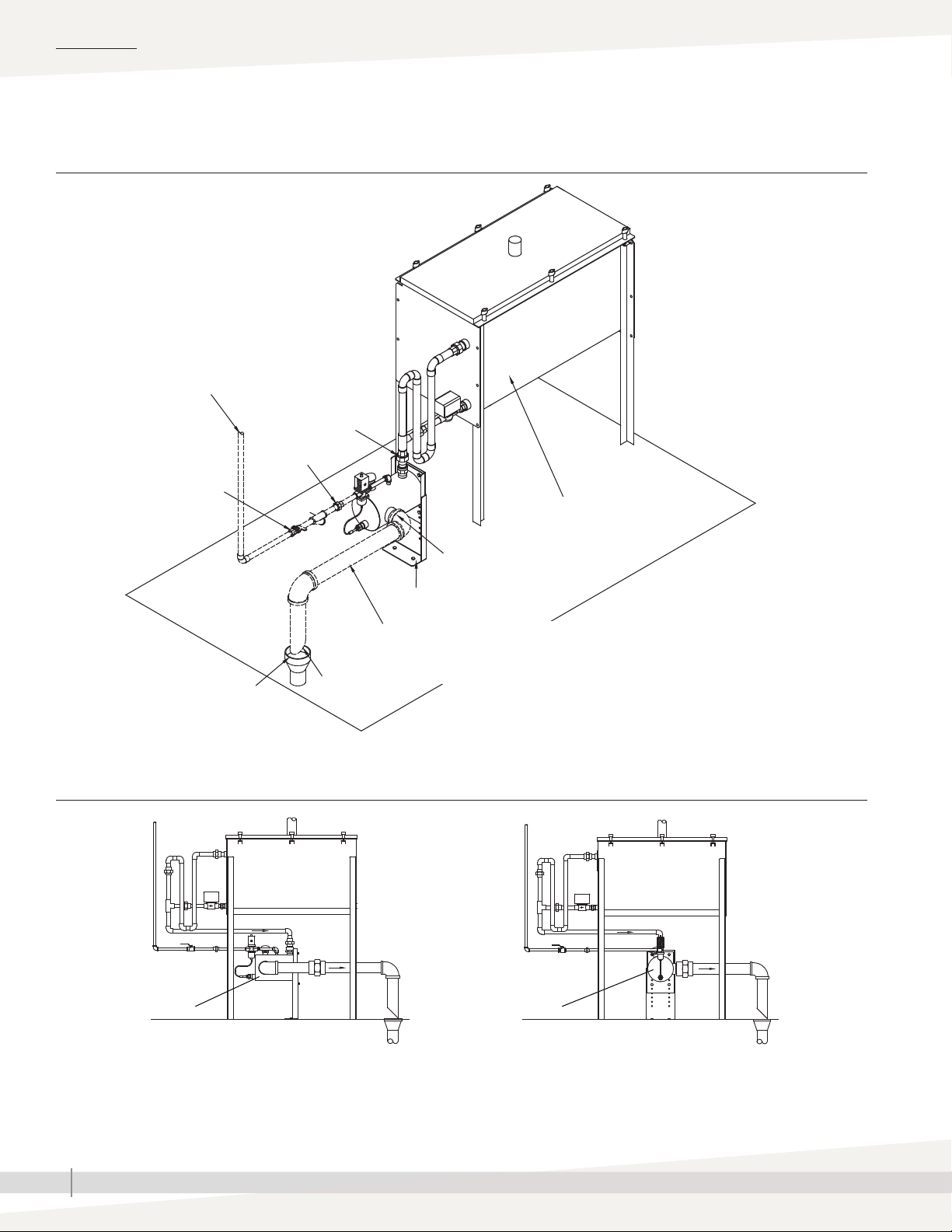
FIGURE 6-1: DRANE-KOOLER PIPING
Cold water supply piping:
3/8” (DN10) pipe thread
Water pressure must be between
25 psi and 80 psi (172 kPa and
552 kPa). Connect directly to the
main water supply line. To ensure
adequate water pressure to the
Drane-kooler, do not connect to a
supply water line that is dedicated
to other appliances.
Cold water
supply shut-off
valve
Cold water inlet
service union:
3/8" (DN10)
pipe thread
Hot water
inlet service
union:
1" (DN25)
pipe thread
Evaporative humidifier
Tempered water outlet service union:
2" (DN50) pipe thread
Anchor mounting plate to floor
Tempered water drain piping:
2" (DN50) pipe thread
Piping must be run full size to drain with no reducers.
Recommended minimum pitch: 1/8" per ft (1%)
Drain
1"
(25 mm)
air gap
before
drain
FIGURE 6-2: DRANE-KOOLER MOUNTED DIRECTLY UNDERNEATH AN EVAPORATIVE HUMIDIFIER
Drane-kooler
OM-1121
Drane-kooler
OM-1120a
OM-1122
Note:
Pitch drain piping at least 1/8"/ft (1%) in direction arrows.
DRISTEEM DRANE-KOOLER WATER TEMPERING DEVICE INSTALLATION, OPERATION, AND MAINTENANCE MANUAL
6
Page 9
Start-up and operating instructions
HOW TO OPERATE
Once properly installed, to operate simply open the cold water supply line.
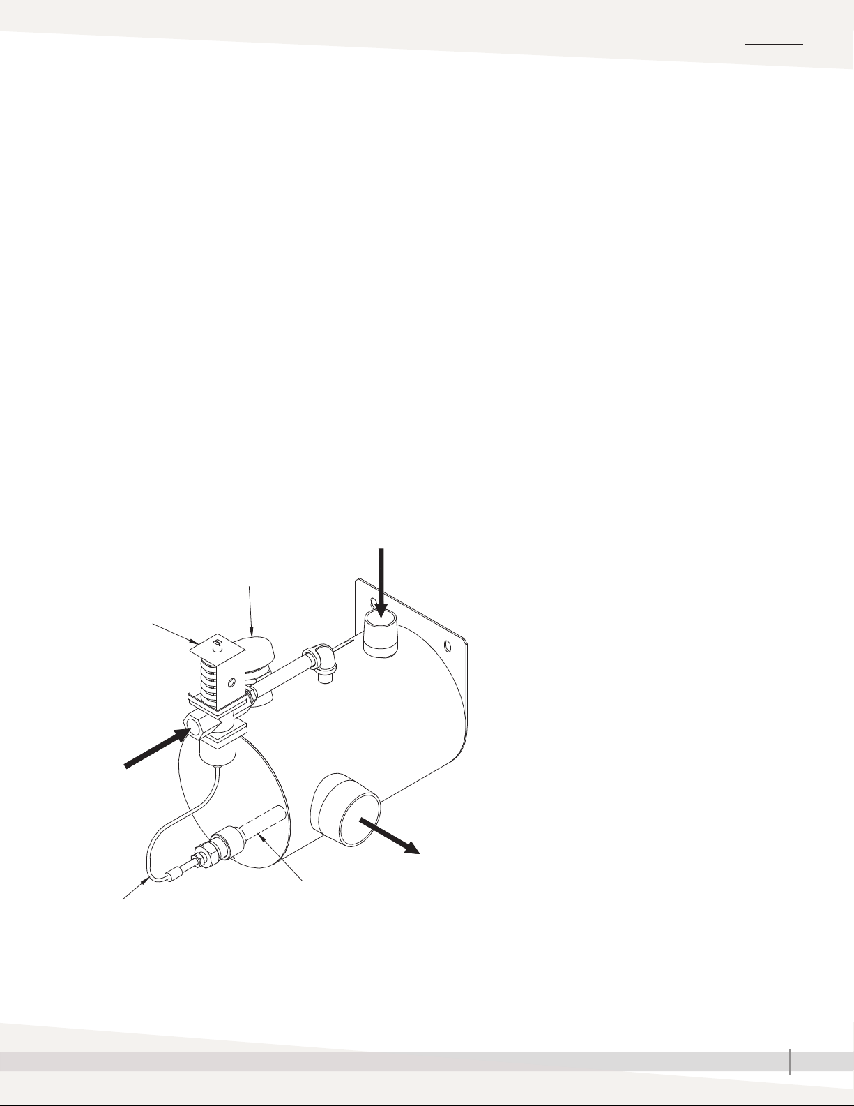
PRINCIPLE OF OPERATION
1. Hot water discharged from a humidifier or other appliance enters the Dranekooler through piping connected to the top threaded connection. The vacuum
breaker prevents backflow into potable water systems.
2. Cold water enters through the temperature-actuated valve. The valve and the
Drane-kooler’s straightforward design ensure efficient mixing of hot and cold
water. The valve’s sensor, located near the outlet, ensures that water leaving
the Drane-kooler is less than 140 °F (60 °C)* before entering the municipal
sewer system.
3. Tempered water at 140 °F (60 °C)* or less exits through the side outlet for
safe discharge into a municipal sewer system or PVC pipe.
*Please see the capacities table on Page 4.
OPERATION
FIGURE 7-1: PRINCIPLE OF OPERATION
Vacuum breaker
Temperature-actuated valve
2
Capillary tube
1
3
Sensor
OM-1114-2
DRISTEEM DRANE-KOOLER WATER TEMPERING DEVICE INSTALLATION, OPERATION, AND MAINTENANCE MANUAL
7
Page 10

MAINTENANCE
Maintenance and troubleshooting
STEP-BY-STEP MAINTENANCE INSTRUCTIONS
1. Shut off cold water supply.
2. Disconnect service unions at:
• Cold water supply inlet
• Hot water inlet
• Tempered water drain outlet
3. Remove the Drane-kooler from piping and take to a service sink. Add
water and, with pipe caps or hands covering the hot water inlet and
tempered water outlet, shake the Drane-kooler to dislodge mineral
deposits. Dump mineral deposits and rinse.
4. If severe mineral accumulation has occurred, remove the thermal sensor
from the Drane-kooler chamber and gently clean the sensor with an
abrasive pad. Do not twist the capillary tube during removal or cleaning.
5. Reconnect service unions and open cold water supply valve to resume
operation.
Table 8-1:
Troubleshooting
Problem Possible cause Action
Remove the Drane-kooler and dislodge mineral
accumulation.
Remove thermal sensor from Drane-kooler and
gently remove mineral accumulation with an
abrasive pad. Do not twist capillary tubing
during removal or cleaning.
Valve is not working properly. Replace.
Note: This valve is factory-set and should not
need adjustment.
The Drane-kooler is designed to handle hot
water and hot condensate. If a large amount
of steam enters the Drane-kooler it is likely that
discharge water temperatures will be greater
than 140 °F (60 °C). Check P-traps on humidifier
or other appliance to ensure that the P-traps
have the proper depth and are working properly
to prevent steam from entering the
Drane-kooler.
If steam is entering the Drane-kooler, the
introduction of cold water through the valve
will cause the steam to collapse and make a
popping or crackling sound. Check P-traps on
humidifier or other appliance to ensure that the
P-traps have the proper depth and are working
properly.
Water leaving the Drane-kooler is hotter than 140°F (60°C)
Makes a loud popping or crackling noise
Mineral accumulation in mixing chamber
Mineral accumulation on thermal sensor
Valve malfunction
Steam is entering the
Drane-kooler
Steam is entering the
Drane-kooler
DRISTEEM DRANE-KOOLER WATER TEMPERING DEVICE INSTALLATION, OPERATION, AND MAINTENANCE MANUAL
8
Page 11
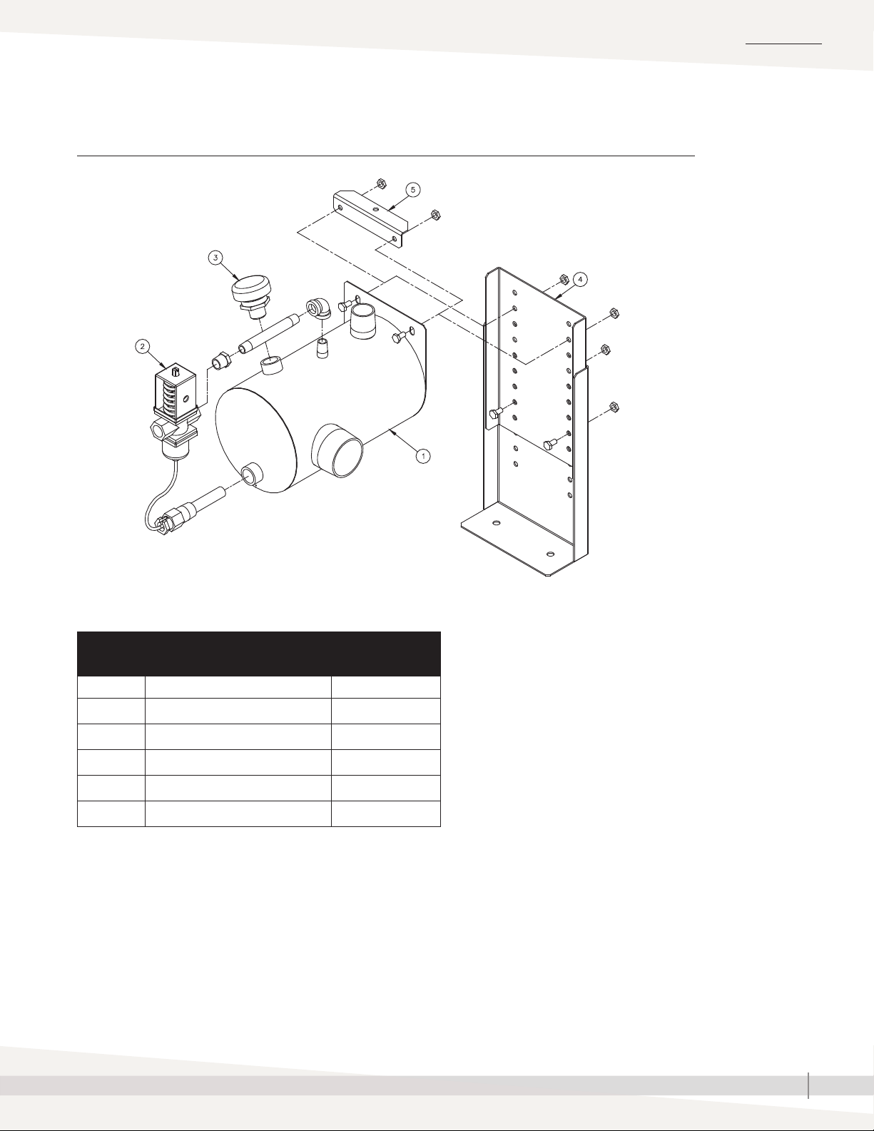
Replacement parts
FIGURE 9-1: REPLACEMENT PARTS
MAINTENANCE
Table 9-1:
Model DK-12 replacement parts
Item Description Part Number
1 Drane-kooler weldment, Model DK-12 167001-020
2 Water tempering valve 505090
3 Valve, 1/2" N36 vacuum relief 320400
4 Floor stand assembly 185110
5 Suspension mount hanger assembly 185100
OM-1119
DRISTEEM DRANE-KOOLER WATER TEMPERING DEVICE INSTALLATION, OPERATION, AND MAINTENANCE MANUAL
9
Page 12

Expect quality from the industry leader
Since 1965, DriSteem has led the industry
with innovative methods for humidifying
and cooling air with precise control. Our
focus on ease of ownership is evident in
the design of the Wetted Media System.
DriSteem also leads the industry with a
Two-year Limited Warranty and optional
extended warranty.
For more information
www.dristeem.com
[email protected]
For the most recent product information
visit our website: www.dristeem.com
DRI-STEEM Corporation
a subsidiary of Research Products Corporation
DriSteem U.S. operations are ISO
9001:2015 certified
U.S. Headquarters:
14949 Technology Drive
Eden Prairie, MN 55344
800-328-4447 or 952-949-2415
952-229-3200 (fax)
European office:
Grote Hellekensstraat 54 b
B-3520 Zonhoven
Belgium
+3211823595
E-mail: [email protected]
Continuous product improvement is a policy
of DriSteem; therefore, product features and
specifications are subject to change without
notice.
DriSteem and Vapor-logic are registered
trademarks of Research Products Corporation
and are filed for trademark registration in
Canada and the European community.
Product and corporate names used in this
document may be trademarks or registered
trademarks. They are used for explanation only
without intent to infringe.
© 2014 Research Products Corporation
TWO-YEAR LIMITED WARRANTY
DRI-STEEM Corporation (“DriSteem”) warrants to the original user that its products will
be free from defects in materials and workmanship for a period of two (2) years after
installation or twenty-seven (27) months from the date DriSteem ships such product,
whichever date is the earlier.
If any DriSteem product is found to be defective in material or workmanship during the
applicable warranty period, DriSteem’s entire liability, and the purchaser’s sole and
exclusive remedy, shall be the repair or replacement of the defective product, or the
refund of the purchase price, at DriSteem’s election. DriSteem shall not be liable for any
costs or expenses, whether direct or indirect, associated with the installation, removal or
reinstallation of any defective product. The Limited Warranty does not include cylinder
replacement for electrode steam humidifiers or media replacement for Wetted Media
Systems.
DriSteem’s Limited Warranty shall not be effective or actionable unless there is
compliance with all installation and operating instructions furnished by DriSteem, or
if the products have been modified or altered without the written consent of DriSteem,
or if such products have been subject to accident, misuse, mishandling, tampering,
negligence or improper maintenance. Any warranty claim must be submitted to
DriSteem in writing within the stated warranty period. Defective parts may be required
to be returned to DriSteem.
DriSteem’s Limited Warranty is made in lieu of, and DriSteem disclaims all other
warranties, whether express or implied, including but not limited to any IMPLIED
WARRANTY OF MERCHANTABILITY, ANY IMPLIED WARRANTY OF FITNESS FOR A
PARTICULAR PURPOSE, any implied warranty arising out of a course of dealing or of
performance, custom or usage of trade.
DriSteem SHALL NOT, UNDER ANY CIRCUMSTANCES BE LIABLE FOR ANY DIRECT,
INDIRECT, INCIDENTAL, SPECIAL OR CONSEQUENTIAL DAMAGES (INCLUDING,
BUT NOT LIMITED TO, LOSS OF PROFITS, REVENUE OR BUSINESS) OR DAMAGE OR
INJURY TO PERSONS OR PROPERTY IN ANY WAY RELATED TO THE MANUFACTURE
OR THE USE OF ITS PRODUCTS. The exclusion applies regardless of whether such
damages are sought based on breach of warranty, breach of contract, negligence, strict
liability in tort, or any other legal theory, even if DriSteem has notice of the possibility of
such damages.
By purchasing DriSteem’s products, the purchaser agrees to the terms and conditions of
this Limited Warranty.
EXTENDED WARRANTY
The original user may extend the term of the DriSteem Limited Warranty for a limited
number of months past the initial applicable warranty period and term provided in
the first paragraph of this Limited Warranty. All the terms and conditions of the Limited
Warranty during the initial applicable warranty period and term shall apply during
any extended term. An extended warranty term of an additional twelve (12) months or
twenty four (24) months of coverage may be purchased. The extended warranty term
may be purchased until eighteen (18) months after the product is shipped, after which
time no extended warranties are available.
Any extension of the Limited Warranty under this program must be in writing, signed by
DriSteem, and paid for in full by the purchaser.
mc_051308_0630
Form No. DK-IOM-1214
Part No. 890000-901 Rev F
 Loading...