

Page 1
READ AND SAVE THESE INSTRUCTIONS
DRI-STEEM
®
CRU SERIES
ELECTRIC STEAM HUMIDIFIERS
Installation Instructions
and
Maintenance Operations Manual
UL RECOGNIZED
COMPONENT
For Toll-Free Customer Support,
Call: 1-800-328-4447
CUL RECOGNIZED
COMPONENT
Page 2

TABLE OF CONTENTS
TO THE PURCHASER AND THE INSTALLER
Thank you for purchasing our CRU® Series humidification equipment. We have designed and built this equipment to
give you total satisfaction and many years of trouble-free service. Proper installation and operating practices will
assure you of achieving that objective. We therefore urge you to become familiar with the contents of this manual.
DRI-STEEM Humidifier Company
CRU Series Humidifiers ............................................................ 3
Installation..................................................................................4
Specifications, Capacities, and Dimensions .......................... 6
Start-up and Operation ............................................................. 8
Maintenance ............................................................................... 10
Trouble-Shooting Guide ........................................................... 11
Replacement Parts..................................................................... 13
Maintenance Service Record .................................................... 19
Two-Year Limited Warranty ...................................................... 20
2
Page 3
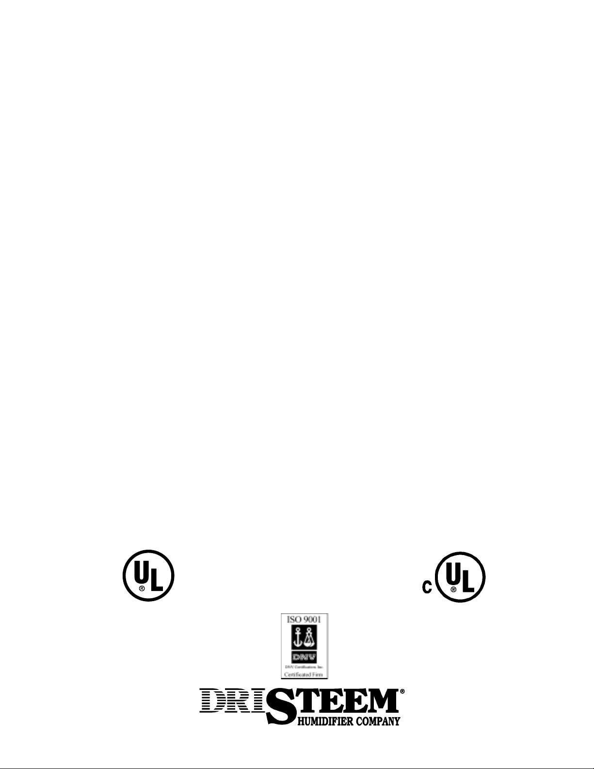
CRU® SERIES HUMIDIFIERS
Figure 3-1: The CRU Humidifier
Figure 3-2: The CRUV Humidifier
(CRUV 2-16 shown, CRUV 25, 34 not shown)
Over Flow
Electrical Conduit
Heater Terminal
Cover
Probe
Electric Drain Valve
Strainer
Fill Valve
Cover Knob
Cover
Steam
Output
OM-771
Steam Output
Heater Terminal Cover
Cover Knob
Over Flow
Electric Drain
Strainer
Probe
Cover
Fill
Valve
Heater
OM-770
CRU Series Humidifiers
This humidifier is designed to be used with either softened or unsoftened water (softened water will greatly reduce
humidifier maintenance and improve overall system performance). The probe-type level control system requires
water conductivity of at least 100 micromhos/cm (2 grains/gal) to function, and therefore, will not operate with
demineralized water. For humidification using demineralized water, see CRUV®-DI below.
Figure 3-3: The CRUV-DI Humidifier
(CRUV-DI 2-16 shown, CRUV-DI 25, 34 not shown)
Heater Terminal Cover
Steam Output
Over Flow
¾" SST
Ball Valve
Water Supply Pipe
Electrical Conduit
Cover Knob
Heater
CRUV®-DI Humidifiers
The evaporating chamber of this humidifier is
constructed of corrosion-resistant stainless steel alloy
to resist the corrosive effects of mineral-free water.
Since the CRUV-DI humidifier is designed for use with
deionized or RO demineralized water, there is no need
to clean the unit, although an annual inspection of the
evaporating chamber is recommended.
Cover
Float Valve
Float
Cut-off
Switch
OM-772
3
Page 4
INSTALLATION
Locate the CRU® humidifier near an electric power source,
water supply and a drain.
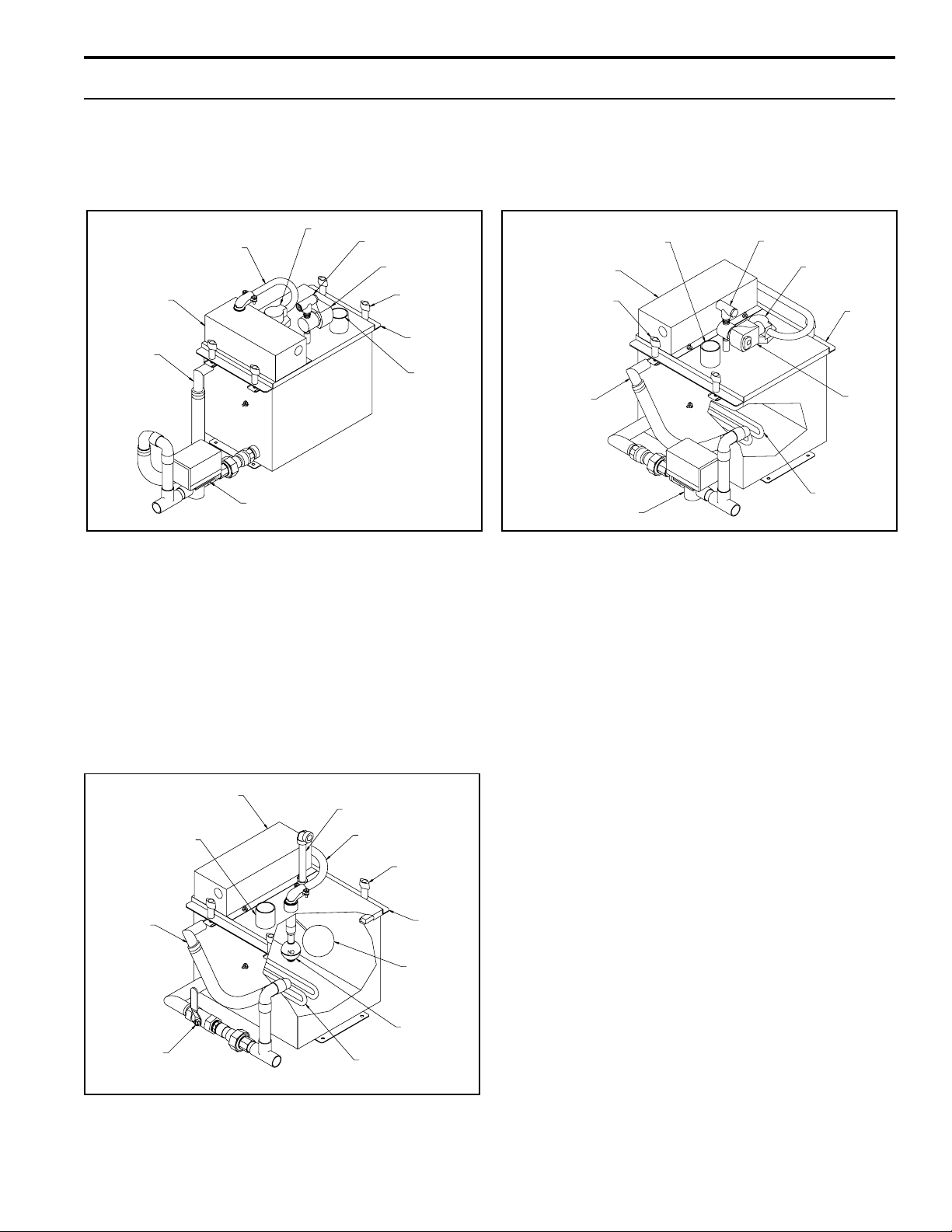
In an Air-Conditioning Unit
When installing a humidifier inside an air conditioning unit,
provide adequate support; allow easy access for removing
and servicing the evaporating chamber, and provide
adequate clearance to install the vapor hose and dispersion tube (see figure 4-1).
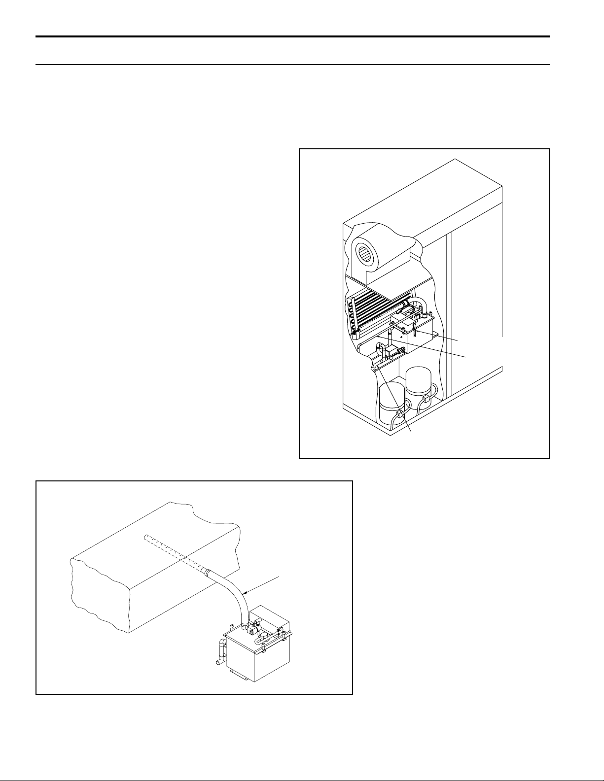
In a Duct
When installing the dispersion tube in a duct, allow for a
continuous pitch of the vapor hose back to the evaporating
chamber. Otherwise, use a water seal and drain (see
examples in figures 4-2 and 5-1). The dispersion tube can
also be placed vertically in the duct with some models
(see figure 5-2).
Place the electrical sub-panel in a grounded protective
metal enclosure and mount in a dry and accessible
location.
If draining the evaporating chamber by gravity is not
possible, use a small condensate lift pump, rated to pump
212° F water.
Examples of Installation in an Air Stream
Figure 4-1: Installation in an Air-Conditioning Unit
Electrical Conduit
Water Supply Pipe
Figure 4-2: Horizontal Dispersion Tube
Duct
Vapor Hose
OM-773
Horizontal mounting of dispersion tube in a duct, connected via vapor hose to
a wall-mounted CRU Series humidifier.
Drain Pipe
OM-830
4
Page 5
INSTALLATION
Piping
Water make-up piping should be of corrosion-resistant,
code-approved material (copper, steel, or plastic). The
final connection size is ¼" NPT. In cases where water
hammer is possible, a shock arrestor should be
considered.
Drain piping should be of code approved material
(copper, steel, or plastic rated for 212°F minimum). The
¾" O.D. copper sweat connection should not be reduced
in size.
If there is no sewer available for drainage, the unit can
be piped for manual drainage. Consult factory for instructions.
Wiring
The CRU
®
is designed for a single source of electric power
supply. Wiring must meet all electrical codes, the current
characteristics, and capacity requirements should be
checked against the nameplates. The electrical subpanel
should be mounted in a location convenient for service.
Wiring must be in accordance with all governing codes,
and with the humidifier wiring diagram. The diagram is
shipped loose with the unit. The wiring between the
control cabinet and humidifier must be
rated at 105°C.
Figure 5-2: Vertical Dispersion Tube
Duct
OM-775
The dispersion tube can be mounted vertically in the duct.
Note: When dispersion tube is more than 10 feet from unit,
insulated, 1½" diameter minimum rigid tubing or pipe should
be used instead of vapor hose. This application is not
recommended for CRUV-16, -25, and -34.
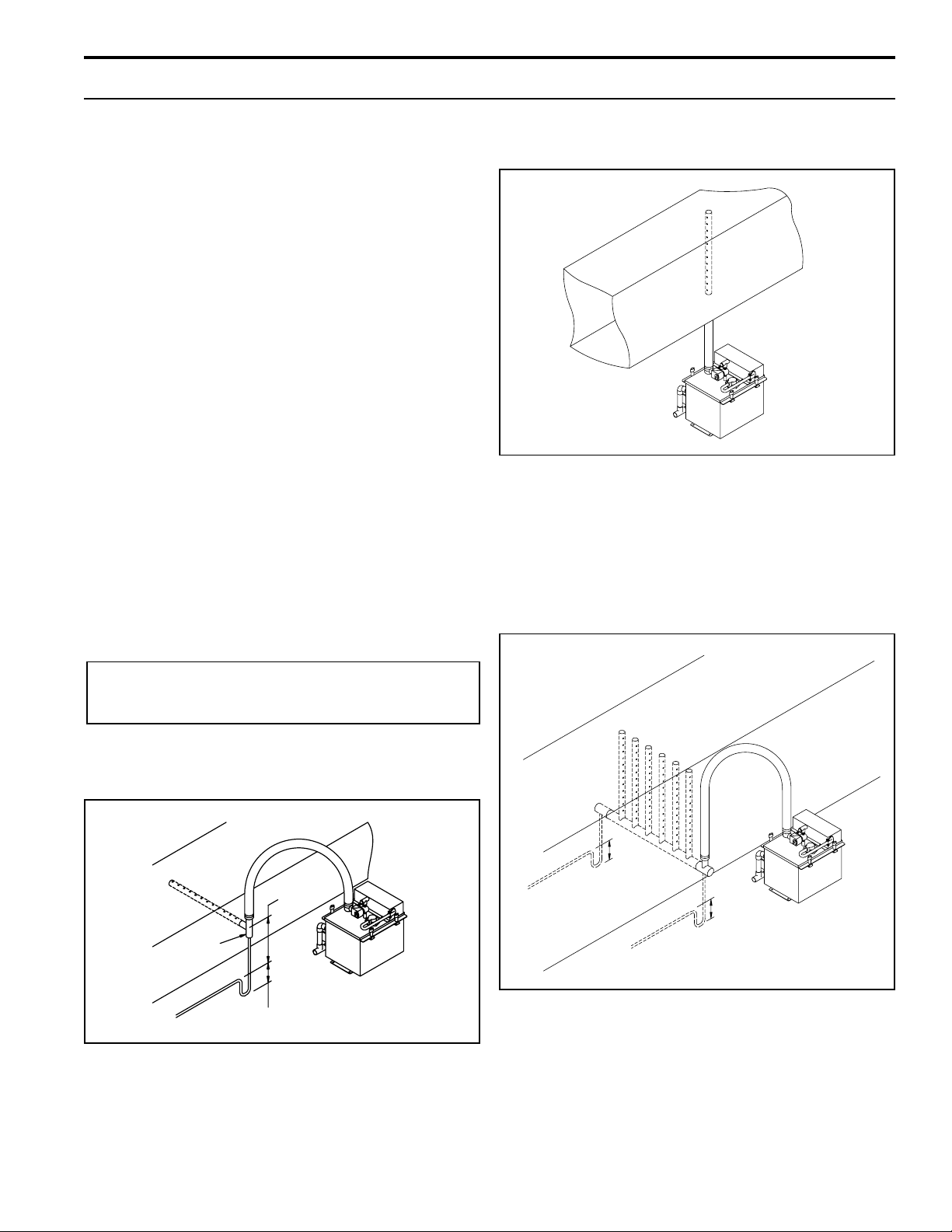
Figure 5-3: RAPID-SORBTM Rapid Absorption Tube
Bank
Caution: Only qualified electrical personnel
should perform installation procedures.
Figure 5-1: Horizontal Dispersion Tube Lower Than
Humidifier
Duct
Tee
3"-5"
Water Seal
OM-774
When horizontally mounting the dispersion tube in an air
stream that is located lower than the CRU Series humidifier a
water seal (to prevent steam from escaping at the open drain)
must be provided in the drain line and line extended to open
drain, as shown, to drain the condensate. A multiple
dispersion tube bank must be used with CRUV-34
because of its high output (see figure 5-3).
Duct
When rapid absorption is extremely critical, a RAPID-SORB
multiple-tube bank can provide 100% steam absorption within
three feet or less - at any duct temperature. Also required for
CRUV-34.
For complete information on calculating the number of
dispersion tubes required to satisfy steam absorption distance
requirements, consult your sales representative, the
DRI-STEEM factory, or use DRI-STEEM's DRI-CALC® II
Humidification Sizing and Selection Software.
TM
5
Page 6
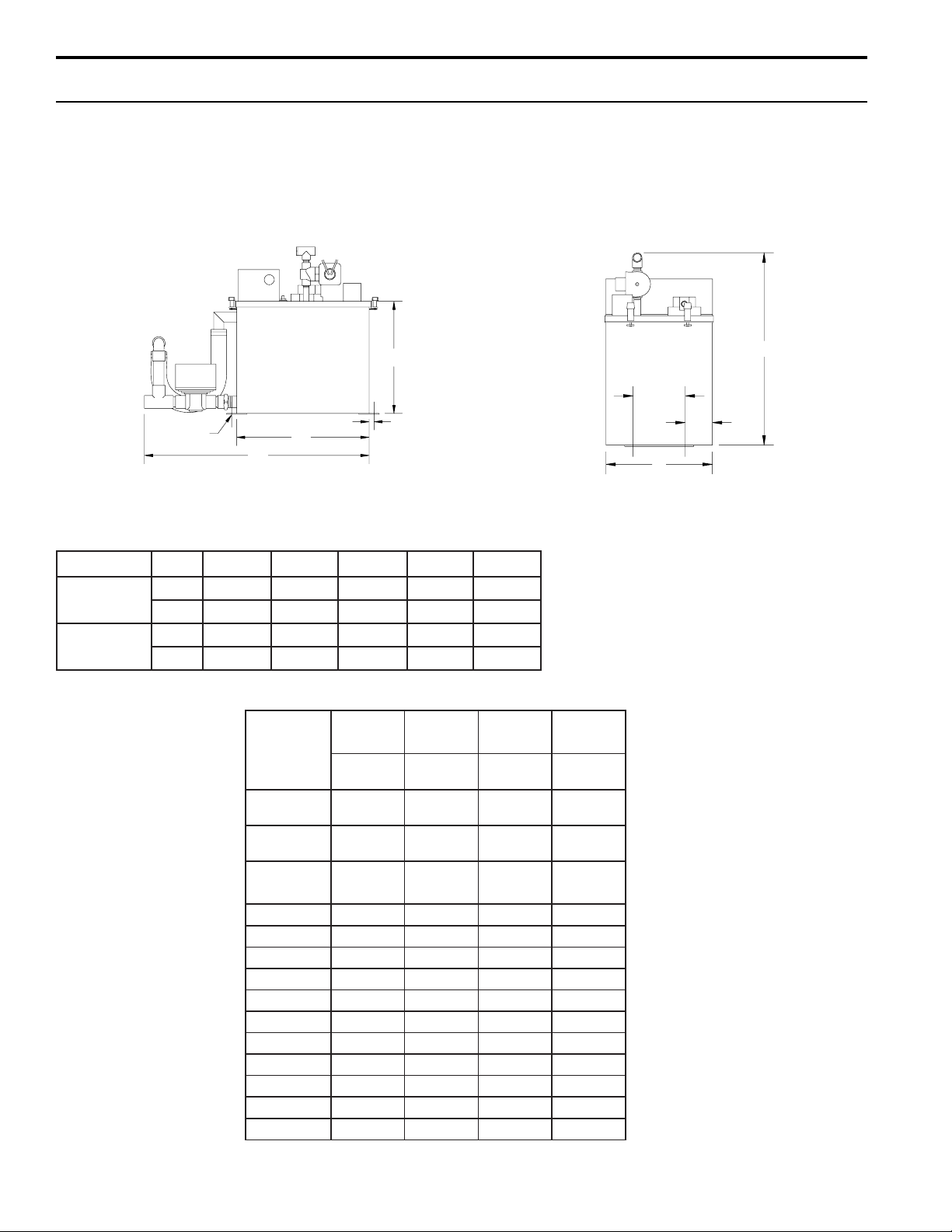
SPECIFICATIONS, CAPACITIES, AND DIMENSIONS
CRU Series
Mechanical/Electrical Specifications
Side Elevation
.25 DIA
A
E
Table 6-1: CRU Dimensions (in inches)
OHGR0$%&'(
4&2-URC
8&6-URC
.ni52.1157.705.805.2152.12
mm582591512513045
.ni52.4157.705.905.3152.42
mm063591042543516
C
.375" TYP
OM-282
End Elevation
D
4.25"
1.75"
OM-283
B
NOTE: The "CRU" differs from the "CRUV" in evaporating chamber size,
heater KW and arrangement of drains and overflow plumbing.
Table 6-2: CRU Mechanical/Electrical Specifications and Capacities
85& 85& 85& 85&
UXRKWXSWX2
JNODJVEO
WZJQLWDUHS2
JNVEO
WZJQLSSLK6
JNVEO
WDVSP$
°Y
°Y 6.92.918.825.83
°Y 0.80.610.429.13
°Y 3.87.610.523.33
°Y 2.43.85.217.61
°Y 3.37.60.013.31
°Y -**7.61**0.52**3.3
°Y -**4.41**7.12**9.82
°Y -**7.8**0.31**3.71
°Y -**2.7**8.01**4.41
°Y -**8.5**7.8**5.11
:. 0.20.40.60.8
* Subtract 9 lbs. (4 kg) from total weight for models without pre-wired subpanel.
** For wire sizing, highest leg draw is shown due to current imbalance in some cases.
7.2/7./64.5/4.1/212.8/2.2/819.01/9.2/42
/245.91/341.42/351.42/35
91
1.41/135.41/239.51/539.51/53
7.61 ---
3
6
Page 7

SPECIFICATIONS, CAPACITIES, AND DIMENSIONS
CRUV® Series
Mechanical/Electrical Specifications
Side Elevation
End Elevation
Side Elevation
(CRUV 25,34)
C
A
.375" TYP
OM-285
E
C
.375" TYP
A
OM-759
Table 7-1: CRUV Dimensions (in inches)
4.25"
B
OHGR0$%&'()*+
D
2.375"
NOTE: Charts shown here can be used for CRUV-DI sizing.
OM-286
.ni53.4105.5100.988.705.1144.1183.26.6
4&2-ID-VURC/VURC
mm46349392200229219233.067.761
.ni53.4100.
01&8,6-ID-VURC/VURC
mm46360456352292492372.8212.632
.ni53.4100.6183.4186.0188.6157.4150.53.9
61&21-VURC/VURC
mm46360456317
.ni53.4100.6183.4152.2188.6152.6150.53.9
43&03,52,12-VURC/VURC
mm46360456311392431472.8212.632
6183.4188.888.6149.2150.53.9
292457372.8212.632
Table 7-2: CRUV Mechanical/Electrical Specifications and Capacities
85& 85& 85& 85&
UXRKWXSWX2
JNODJVEO
WZJQLWDUHS2
JNVEO
WZJQLSSLK6
JNVEO
WDVSP$
°Y
°Y 6.92.918.825.83
°Y 0.80.610.429.13
°Y 3.87.610.523.33
°Y 2.43.85.217.61
°Y 3.37.60.013.31
°Y -**7.61**0.52**3.33
°Y -**4.41**7.12**9.82
°Y -**7.8**0.31**3.71
°Y -**2.7**8.01**4.41
°Y -**8.5**7.8**5.11
:. 0.20.40.60.8
* Subtract 9 lbs (4 kg) from total weight for models without pre-wired subpanel.
** For wire sizing, highest leg draw is due to current unbalance in some cases.
7.2/7./64.5/4.1/212.8/2.2/819.01/9.2/42
/245.91/341.42/351.42/35
91
1.41/135.41/239.51/539.51/53
7.61 ---
7
Page 8

START-UP AND OPERATION
Start-up and Checkout Procedures
After the system has been properly installed and connected to both electrical and water supplies, it may then
be started.
Mounting
Check mounting to see that the unit is level and securely
supported before filling with water.
Piping
Verify that all piping connections have been completed as
recommended and that water pressure is available.
Electrical
Verify that all wiring connections have been made in
accordance with all governing codes and the enclosed
wiring diagram.
Caution: Only qualified personnel should
perform start-up procedure.
Figure 8-1: Electronic
Probe Control for
Maintaining Proper
Water Level (CRU
®
and CRUV®)
A
B
C
OM-211
LW415 Electronic Water Level Control
Module
When the power is activated, the solenoid-operated water
fill valve will open, filling the evaporating chamber. Filling
will continue until water reaches level A, at which time the
fill valve will close. To ensure that a water seal is created
in the overflow hose, disconnect probe plug and cable
from probe rod assembly (located on cover), allowing the
fill valve to re-energize and overfill humidifier tank. This
process will take only seconds; probe plug and cable
must then be reconnected. A call for humidity will then
energize the heating element.
Water Refill
During operation, when the water line drops below level B
the fill valve opens, and remains open until the water line
returns to level A.
Heater Protection
Should the water line ever drop below level C, the heaters
are de-energized and remain OFF until the water line has
been restored to level C. This feature provides heater
protection in the event of a low-water condition.
Surface Skimmer
Each time the evaporating chamber refills, the upper
1/4" of water is immediately drained off through the
skimmer. This drains away the mineral residue formed
during the previous evaporating cycle. This skimming
action effectively removes most of the mineral precipitate
in much the same way as a surface blowdown does in a
steam boiler. This simple device greatly extends the
time between evaporating chamber cleanings.
A simple three-probe conductivity sensor cycles a
solenoid-operated water fill valve to maintain the proper
water levels.
The CRU® Series humidifiers are available with either the
standard LW 415 Electronic Water Level Control Module
or the optional VAPOR-LOGIC
®
microprocessor control
2
system. If your system is equipped with the
VAPOR-LOGIC2 system, see the VAPOR-LOGIC
2
Operations and Maintenance Manual for more information.
Then continue reading this manual beginning at the
maintenance section on page 10.
8
Drain/Flush Feature
This control module contains an integral electronic timer
which tracks the humidifying time of the unit. When this
accumulated time reaches what has been set in the
timer, the drain/flush cycle is activated.
Upon activation, the following sequence occurs:
1. The drain valve opens and begins to drain surface
water and minerals from the evaporating chamber.
2. When the height of the water drops to the “REFILL”
level, the fill valve opens.
3. The drain and fill valves remain open for ten more
minutes, flushing the chamber.
Page 9

START-UP AND OPERATION
4. The drain valve then closes, the chamber refills, and
the fill valve closes. The timer resets and the unit
resumes normal operation.
The electronic timer comes factory-set for drainage after
40 hours of operation. Alternate settings of 20 hours and
80 hours are available. See wiring diagram(s) attached to
unit for timer board location and instructions for changing
the timer setting.
Test Cycling the Drain/Flush System
The level control board contains four pairs of terminal
pins which are marked 20, 40, 80 and “T” (TEST). To
test:
1. Pull the pin block off the pair of pins in use, move it to
the “T” pair, and push it on.
2. Set the humidistat high enough so that unit will remain
“on call” for at least one hour.
3. After about 35 minutes of operation, activation will
take place, causing the drain valve to open. Th e
water level will then drop to level B (see figure 8-1 on
page 8) and cause the fill valve to open. Both valves
will remain open for about 10 minutes.
4. The drain valve will then close, and the water level
will rise to level A (see figure 8-1 on page 8), causing
the fill valve to close.
5. Once the test cycle is complete, move the pin block
back to the desired pair of pins. Failure to do so
will result in a drain/flush cycle every 35 minutes.
protection in the event of a low-water condition is common
to all DI humidifiers and can be found in the wiring diagram shipped with the unit.
CRUV-DI Start-Up Procedure
a) Adjust humidistat to "call" setting.
b) Open shut-off valve on water supply line. Unit should
begin filling with water through the fill valve.
c) Shortly before the fill valve shuts off, the float
operated heater cut-off switch will "make." When
this switch makes, the heating element contactor(s)
will be actuated. A time delay relay circuit prevents
contactor chatter due to bouncing of heater cut-off
float.
d) Check heater cut-off circuit.
1. Close manual valve on water supply.
2. Open drain valve and start draining unit.
3. When water level drops past switching level on
the heater cut-off float, the heating element
contactor(s) will drop out.
4. When step 3 has been satisfactorily completed,
close drain valve.
e) Check function of field-installed safety controls,
such as the fan proving switch. Contactor(s) should
drop out when any proving switch is "open."
f) Check heater draw by testing and recording voltage
and amperage in each phase. Readings should
match name plate readings; name plate is located on
the humidifier housing.
g) Inspect installations for steam or air leaks while
operating the humidifier. Any leaks should be
sealed.
CRUV® Make-up Water Piping
If the water pressure is above 60 psi and/or water hammer would be objectionable, a pressure-reducing valve or
shock arrester should be installed. Even though the
humidifier has an internal 1" air gap, some local codes
may require a vacuum breaker.
Important: Minimum water supply pressure is 25 psi.
CRUV®-DI Water Level Control System
The basic water level system and circuit for heater
Caution
Overtightening will cause leaks.
All cover knobs are turned down at the factory until
the bottom of the knob makes contact with the
flange, then one half turn further. If more
compression is required, turn all knobs a half turn
more. Do not turn knobs more than a half turn
before identifying that a leak still exists.
9
Page 10

MAINTENANCE
CRU® and CRUV® Humidifiers
(Non-DI humidifiers with either the LW 415 or
VAPOR-LOGIC
Mineral Precipitate
As evaporation takes place in the CRU humidifier, some
of the minerals dissolved in the water precipitate out and
float on the water surface. The minerals not removed by
the skimmer will settle to the bottom of the evaporating
chamber.
Cleaning the Evaporating Chamber
The heating element itself is self-cleaning. The mineral
buildup on the element flakes off after reaching a thickness of about 1/16", and settles to the bottom of the
chamber.
Long heater element life can be expected when the
operation of the humidifier is observed for a few weeks
following initial start-up. By observing the mineral build-up
rate, the frequency of both drain/flush use and manual
cleaning can be determined and adjustments made.
Cleaning once or twice a season is usually adequate,
assuming the water has no more than 15 grains of
hardness per gallon.
CAUTION: Before this mineral scale builds up on
the underside of the heating element, it must be
removed. Failure to do so may result in premature
heater burn-out.
The CRU humidifier is designed for convenient cleaning
and maintenance.
To Service:
1. Shut off all electrical power to humidifier. Drain
evaporating chamber by manually opening
DRAIN valve. Do this by moving lever on valve to
MANUAL position and lock in place.
2. Disconnect flexible vapor hose from evaporating
chamber.
3. Unscrew utility knobs and remove cover.
4. Disconnect overflow hose and drain valve.
5. Remove evaporating chamber and clean.
6. Unscrew probe-rod assembly. Scale should flake
off easily. Build-up on tips should be scraped off to
remove any mineral residue.
7. Replace chamber cover, making sure chamber is
sealed tight.
Control Systems)
2
8. Reconnect flexible vapor hose, overflow hose and
drain valve.
9. Verify drain valve lever is in AUTO position.
10. The CRU humidifier is again ready to humidify
when power is restored.
Off-Season Shutdown
1. Switch off power.
2. Turn off water supply to make-up valve.
3. Drain evaporating chamber and clean if necessary
(see steps 1 through 9 above).
4. Leave chamber dry, power OFF and water shut-off
valve closed until the next humidification season.
CRUV®-DI Humidifier
To Service
1. Shut off electric power to unit
2. Shut off water supply to make-up valve.
3. Allow time for evaporating chamber to cool.
4. Make sure evaporating chamber is drained by
manually opening the drain valve.
5. Check condition of the overflow hose.
6. Remove evaporating chamber as follows:
Disconnect flexible vapor hose on top of evaporating
chamber. Close drain valve. Disconnect unit from
drain. DO NOT DISCONNECT ANY OF THE
ELECTRICAL CONDUITS.
7. Unscrew utility knobs and remove cover.
8. Check operation of float valve and low-water cut-out.
9. Inspect heating elements.
10. Inspect evaporating chamber and clean if necessary.
11. Inspect cover gasket, and replace if necessary.
12. Replace chamber cover.
13. Reconnect all flexible hoses.
14. Verify drain valve is in the closed position.
15. Open water supply valve and turn on electric power.
16. CRUV-DI humidifier is again ready to humidify.
Off-Season Shutdown Procedure
1. Switch off electrical power to unit.
2. Check overall appearance of unit.
3. Shut off water supply to make-up valve.
4. Drain evaporating chamber by manually opening
drain valve.*
5. Visually check electrical components of subpanel.
6. Leave chamber dry, power off, and water shut-off
valve closed until the next humidification season.
* With VAPOR-LOGIC2 option, the evaporating chamber is automatically
drained after 72 hours without a call for humidity.
10
Page 11

CRU® TROUBLE-SHOOTING GUIDE (LW415 Electronic Water Level System Only)*
CONTROL PANEL
LIGHTS
PROBLEM FILL READY DRAIN POSSIBLE CAUSE RECOMMENDED ACTION
WATER
Humidifier will Off Off Off Control transformer Verify control voltage across secondary
not heat leads of transformer. Reset transformer
circuit breaker.
Off On Off Humidistat is not calling Set humidistat to call. Inspect for faulty
Safety controls open Check safety controls, air flow switch, high
Faulty control board Verify control voltage between terminals
Probe head deterioration** Replace probe head.
Humidifier will On Off Off No water pressure at valve. Check water supply/shut off valves.
not fill
Faulty water fill valve Verify action of fill water solenoid valve by
Plugged strainer Check strainer.
Plugged valve Check valve.
Faulty control board Verify control voltage across terminals
Humidifier does On Off Off Lack of tank to probes Jumper wires brown to yellow. If water
not stop filling electrical continuity. Water stops, verify tank ground; check water
conductivity 100 supply conductivity; then consult factory.
micromhos/cm (2 gr/gal) min.
humidistat.
limit humidistat, etc.
H & N.
turning control module switch from standby
to normal op. Audible click should be
heard as solenoid operates.
H & N.
Fill valve is stuck open Check valve for foreign matter.
Drain Valve not closed Check for correct water flow through valve
Fill valve installed backward note arrow.
On Off On Auto-drain mode 10 Minute must complete first.
Low output Off On Off Electric drain valve not Correct cause of leakage or replace valve.
seating
Off On Off Fill valve is stuck open Check valve for foreign matter.
Unit short cycles
Reduced or no Off On Off Heater malfunctioning Verify that proper voltage is being applied to
output even heaters. Check heater (amp draw and
though water compare to wiring diagram ratings).
is at the proper
level
*For VAPOR-LOGIC2 trouble-shooting, see the VAPOR-LOGIC2 Operations and Maintenance Manual.
**Probe rod corrosion or probe head material aging may cause level control system failure. This generally does not occur in the first two years of operation.
On & Off
On Off Probes may be incorrectly Confirm that unit is wired per diagram.
wired or need cleaning Clean probe rod tips with steel wool.
Malfunctioning control Heater contactor not functioning--replace.
system Service fuses blown. Auxiliary limit controls
not allowing system to operate (dust humidistat, air flow proving switch, etc.). Reset,
replace or calibrate as required. Faulty or
inaccurate humidistat, replace or calibrate.
11
Page 12

CRUV® -DI TROUBLE-SHOOTING GUIDE (LW415 Electronic Water Level System Only)*
PROBLEM
Humidifier will
not heat
Humidifier will
not fill
Water float
valve does not
close
READY
WATER
Off
Off
On
POSSIBLE CAUSE
Control transformer
Humidistat is not calling
Safety controls open
Low water float switch
No water pressure at valve
Malfunctioning water float
valve
Plugged float valve
Open drain valve
Manual drain valve not closed
RECOMMENDED ACTION
Verify control voltage across secondary leads of
transformer. Reset transformer circuit breaker.
Set humidistat to call. Inspect for faulty humidistat.
Check safety control. (Air flow switch, high limit
humidistat, etc.)
Verify control voltage from float switch and transformer
secondary common.
Check manual water supply. Valve, minimum 30 psi
water pressure.
Check to make sure that valve float & stem moves freely.
Check float valve seat.
Obstruction in drain valve will not allow complete
closure, clean or replace valve.
Close drain valve.
Malfunctioning float valve
Water passing into overflow
stand pipe
Float valve stuck
Reduced or no
output even
though water is
at the proper
level
*For VAPOR-LOGIC2 trouble-shooting, see the VAPOR-LOGIC2 Operations and Maintenance Manual.
On
Heater malfunctioning
Malfunctioning control system
Time delay/interlock relays
Low water cut-off switch
Float ball has water leak. Float valve seat defective,
replace.
Readjust float valve rod, so water level reaches 1/4-3/8"
from overflow edge when water is at ambient or cold
state. Excessive water pressure, 100 psi maximum.
Obstruction will not allow float valve to seat properly,
clean or replace with new seat.
Verify that proper voltage is being applied to heaters.
Check heaters (amp draw and compare to wire diagram
ratings).
Heater contactor not functioning, replace. Service fuses
blown. Auxiliary limit controls not allowing system to
operate (duct humidistat, air flow proving switch, etc.).
Reset, replace, or calibrate as required. Faulty or
inaccurate humidistat, replace or calibrate.
On delay relay delay time is 10-15 seconds. Check
relays.
Check for proper operation.
12
Page 13

REPLACEMENT PARTS
Table 13-1: CRU
No. Description Part No.
1 Tank 160712*
2Cover *
3 Cover, Heater Terminal 160750*
4 Gasket, Cover 160695*
5 Knob, T-Handled Utility 700725
6 Heater 409600*
7 Thermo Cut-Out 409560-001
8 Strainer, 1/4" NPT Sediment 300050
9 Orifice, .041 Fill Valve 160225-002
10 Valve, 1/4" Solenoid Fill 505084
11 Gasket, Probe 309750-003
12 Probe Assembly, CRU 406220
13 Probe Plug Wire Assembly, 24" 406050-002
14 Probe Housing, Nylon 308500
15 Drain Assembly, CRU 180250*
16 Valve, 3/4" HW Hydronic Drain 505400-001
17 Hose, Overflow 307020-002
18 Hose Clamp, 3/4" I.D. 700560-075
19 Spri ng , Overflow H o se 307025
®
OM-778
* Specify humidifier model and serial numbers when ordering.
13
Page 14

REPLACEMENT PARTS
OM-779
Table 14-1: CRUV® 2-16
No. Description Part No.
1 Tank 160701*
2 Cover *
3 Cover, Heater Terminal 160750*
4 Gasket, Cover 160695
5 Knob, T-Handled Utility 700725
6 Heater 409600*
7 Thermo Cut-Out 409560-001
8 Strainer, 1/4" NPT Sediment 300050
9 Orifice, .041 Fill Valve 160225-002
10 Valve, 1/4" Solenoid Fill 505084
11 Gasket, Probe 309750-003
12 Probe Assembly, CRUV *
13 Probe Plug Wire Assembly, 24" 406050-002
14 Probe Housing, Nylon 308500
15 Drain Assembly, CRUV 180200*
16 Valve, 3/4" Electric Drain 505400-001
17 Hose, Overflow 307020-002
18 Hose Clamp, 3/4" I.D. 700560-075
19 Spring, Overflow Hose 307025
14
* Specify humidifier model and serial numbers when ordering.
Page 15

REPLACEMENT PARTS
Table 15-1: CRUV®-25, 34
No. Description Part No.
1 Tank 160701*
2Cover *
3 Cover, Heater Terminal 160750-010
4 Gasket, Cover 160695-002
5 Knob, T-Handled Utility 700725
6 Heater 409600*
7 Thermo Cut-Out 409560-001
8 Strainer, 1/4" NPT Sediment 300050
9 Orifice, .052 Fill Valve 160225-005
10 Val ve, 1/4" So l e no i d Fi ll 5050 84
11 Gasket, Probe 309750-003
12 Probe Assembly, CRUV-25, 34 406200
13
14 Probe Housing, Nylon 308500
15 Drain Assembly, CRUV-25, 34 180200-007
16 Valve, 3/4" HW Hydronic Drain 505400-001
17 Hose, Overflow 307020-002
18 Hose Clamp, 3/4" I.D. 700560-075
19 Spring, Overflow Hose 307025
Probe Plug Wire Assembly, 24"
(without conduit)
406050-003
OM-1014
* Specify humidifier model and serial numbers when ordering.
15
Page 16

REPLACEMENT PARTS
Table 16-1: CRUV®-DI 2-16
No. Description Part No.
1 Tank 160701*
2 Cover *
3 Cover, Heater Terminal 160750*
4 Gasket, Cover 160695*
5 Knob, T-Handled Utility 700725
6 Heater 409600*
7 Thermo Cut-Out 409560-001
8 Elbow 1/4" 90° 200580
9 Pipe Weld, CRUV-DI, 2-16 Fill Valve 160210
10 Orifice, .041 Fill Valve 160225-001
11 Seal Ring, 1/4" 18 NPT 306365
12 Float Valve Assembly, CRUV-DI *
13 Float Switch, Stainless Steel LWCO 408420
14 Drain Assembly, CRUVDI 180180*
15 Valve, 3/4" Stainless Steel Ball 505000-001
16 Hose, Overflow 307020-002
17 Hose Clamp, 3/4" I.D. 700560-075
18 Spring, Overflow Ho se 30 70 25
OM-780
16
* Specify humidifier model and serial numbers when ordering.
Page 17

REPLACEMENT PARTS
OM-1015
Table 17-1: CRUV®-DI 25, 34
No. Description Part No.
1 Tank 160701*
2 C over *
3 C over, Heater Terminal 160750-010
4 Gasket, Cover 160695-002
5 Knob, T-Handled Utility 700725
6 H eater 409600*
7 Thermo Cut-Out 409560-001
8 DI Conversion Weld, CRUV-DI 25, 34 167786
9 Pipe Weld, CRUV-DI 25, 34 Fill Valve 160215
10 Orifice, .052 Fill Valve 160225-004
11 Se a l Ring, 1/4" 18 NPT 306365
12 Float Valve Assembly, CRUV-DI 25, 34 505230
13 Fl oat Switch, Stainless Steel LWCO 408420
14 Drain Assembly, CRUV-DI 25, 34 180180-005
15 Valve, 3/4" Stainless Steel Ball 505000-001
16 Hose, Overflow 307020-002
17 Hose Clamp, 3/4" I.D. 700560-075
18 Spring, Overflow Hose 307025
19 DI Housing, Nylon 167780
20 Gasket, CRUV-DI 25, 34 Conversion Weld 160698
* Specify humidifier model and serial numbers when ordering.
17
Page 18

REPLACEMENT PARTS
Table 18-1: CRUV® Control Cabinet (with LW430)
No. Description Part No.
1 C ontrol Cabi net, 16 x 14 x 6 407100-005
2 Display Board, LW430 4086 51
3 Microprocessor Board, LW430 408641
4 Transformer, 208/240/480V 408965
4 Transformer, 120V 408960
4 Transformer, 575V 408984
5 C ontactor, 24V 407001*
6 Ground Lug, L-35 409250-017
7 Terminal Block, 3-Pole 408300-002
* Specify humidifier model and serial numbers when ordering.
Table 18-2: CRU® and/or CRUV® Control Cabinet (with TP Modulator)
No. D escription Part No.
1 Control Cabinet, 16 x 14 x 6 407100-005
2 TP Modulator 408680*
3 LW15 Modulator 180600
4 Transformer, 208/240/480V 408965
4 Transformer, 120V 408960
4 Transformer, 575V 408984
5 Contactor, 24V 407001*
6 Ground Lug, L-35 409250-017
7 Terminal Block, 3-Pole 408300-002
8 Terminal Block, 16 Position 408250-009
OM-1017
* Specify humidifier model and serial numbers when ordering.
Table 18-3: CRUV®-DI Control Cabinet
No. Description Part No.
1 Control Cabinet, 12 x 12 x 6 407100-004
2 TP Modulator 408680*
3 Time Delay, 24V 408440-001
4 Transformer, 208/240/480V 408965
4 Transformer, 120V 408960
4 Transformer, 575V 408984
5 Contactor, 24V 407001*
6 Ground Lug, L-35 409250-017
7 Terminal Block, 3-Pole 408300-002
8 Terminal Block, 9 Position 408250*
9 Relay, 24V 407900-001
* Specify humidifier model and serial numbers when ordering.
18
OM-1016
OM-1018
Page 19

MAINTENANCE SERVICE RECORD
DATE INSPECTED PERSONNEL OBSERVATION ACTIONS PERFORMED
19
Page 20

TWO-YEAR LIMITED WARRANTY
DRI-STEEM Humidifier Company (“DRI-STEEM”) warrants to the original user that its products will be free
from defects in materials and workmanship for a period of two (2) years after installation or twenty-seven
(27) months from the date DRI-STEEM ships such product, whichever date is the earlier.
If any DRI-STEEM product is found to be defective in material or workmanship during the applicable warranty period, DRI-STEEM’s entire liability, and the purchaser’s sole and exclusive remedy, shall be the
repair or replacement of the defective product, or the refund of the purchase price, at DRI-STEEM’s election. DRI-STEEM shall not be liable for any costs or expenses, whether direct or indirect, associated with
the installation, removal or reinstallation of any defective product.
DRI-STEEM’s limited warranty shall not be effective or actionable unless there is compliance with all installation and operating instructions furnished by DRI-STEEM, or if the products have been modified or altered
without the written consent of DRI-STEEM, or if such products have been subject to accident, misuse,
mishandling, tampering, negligence or improper maintenance. Any warranty claim must be submitted to
DRI-STEEM in writing within the stated warranty period.
DRI-STEEM’s limited warranty is made in lieu of, and DRI-STEEM disclaims all other warranties, whether
express or implied, including but not limited to any IMPLIED WARRANTY OF MERCHANTABILITY, ANY
IMPLIED WARRANTY OF FITNESS FOR A PARTICULAR PURPOSE, any implied warranty arising out of
a course of dealing or of performance, custom or usage of trade.
DRI-STEEM SHALL NOT, UNDER ANY CIRCUMSTANCES BE LIABLE FOR ANY DIRECT, INDIRECT,
INCIDENTAL, SPECIAL OR CONSEQUENTIAL DAMAGES (INCLUDING, BUT NOT LIMITED TO, LOSS
OF PROFITS, REVENUE OR BUSINESS) OR DAMAGE OR INJURY TO PERSONS OR PROPERTY IN
ANY WAY RELATED TO THE MANUFACTURE OR THE USE OF ITS PRODUCTS. The exclusion applies
regardless of whether such damages are sought based on breach of warranty, breach of contract, negligence, strict liability in tort, or any other legal theory, even if DRI-STEEM has notice of the possibility of such
damages.
By purchasing DRI-STEEM’s products, the purchaser agrees to the terms and conditions of this limited
warranty.
14949 Technology Drive, Eden Prairie, MN 55344
PH: 1-800-328-4447 • In MN: (612) 949-2415
Fax: (612) 949-2933 • E-Mail: sales@dristeem.com
s
o
,
y
n
r
b
o
e
c
a
n
%
a
0
n
0
Printed on recycled paper with
Printed on recycled paper with agribased inks
agri-based inks. Minimum 10%
1
:
s
k
n
i
d
e
s
a
b
i
r
g
A
d
v
e
g
e
t
a
b
l
e
o
i
l
s
.
Post-consumer Waste.
Form No. CRUOM-0996 Copyright © 1996 DRI-STEEM Humidifier Company, Inc. Printed in the U.S.A.
20
 Loading...