

DriSteem 401, 402, 404, 406, 403 Installation, Operation And Maintenance Manual
...
READ AND SAVE THESE INSTRUCTIONS
WATER TREATMENT
400 series
reverse-osmosis systems
Installation, Operation,
and Maintenance Manual

DRISTEEM WATER TREATMENT SYSTEMS INSTALLATION, OPERATION, AND MAINTENANCE MANUAL
ii
Warnings and cautions
WARNING
Attention installer
Read this manual before installing, and leave this manual with product owner. This product must be installed by qualifi ed
plumbing, HVAC and/or electrical contractors. Installation must be code approved.
Disconnect electrical power
Disconnect electrical power before installing supply wiring or performing service or maintenance procedures on any part
of the system. Failure to disconnect electrical power could result in fi re, electrical shock, and other hazardous conditions.
These hazardous conditions could cause property damage, personal injury, or death.
Contact with energized circuits can cause property damage, severe personal injury, or death as a result of electrical shock
or fi re. Do not remove pump cover, or subpanel access panels until electrical power is disconnected.
Follow the shutdown procedure in this manual before performing service or maintenance procedures on any part of the
system.
mc_052410_1510
Electric shock hazard
If the reverse-osmosis system starts up during maintenance, severe bodily injury or death from electric shock could occur.
To prevent such start-up, follow the procedure below before performing service or maintenance procedures on this reverseosmosis system:
1. Use Vapor-logic
2. Shut off all electrical power to the reverse-osmosis system using fi eld-installed fused disconnect, and lock all power
disconnect switches in OFF position.
3. Close fi eld-installed manual water supply shut-off valve.
mc_050808_1540
Tipping hazard
Before installing the 400 series reverse-osmosis system, use supplied leg brackets or lag points to permanently fi x the
system to the fl oor and/or adjacent building structure. Failure to install according to instructions can result in serious injury
or death. See page 13 for instructions.
®
keypad/display to change control mode to Standby.
WARNINGS AND CAUTIONS
Team lift required
Team lift is required when replacing the membranes. Membrane banks are heavy. Do not try to lift without assistance.
Wear steel-toed shoes and have adequate room for maneuvering when servicing. Never lean membrane banks vertically
when removed from system. Failure to do so may damage the system or result in injury. See maintenance information on
page 38.
DRISTEEM WATER TREATMENT SYSTEMS INSTALLATION, OPERATION, AND MAINTENANCE MANUAL
iii

WARNINGS AND CAUTIONS
Warnings and cautions
CAUTION
Operate system at above-freezing temperatures.
Operating the system at temperatures below freezing can damage the system or cause other property damage.
Maintain pumping and water treatment equipment.
Inadequately maintained pumping and water treatment equipment can cause the system to fail. Refer to the maintenance section
of this IOM for recommended maintenance.
Do not install the system using steel or galvanized-steel piping and joints.
Steel and steel-galvanized piping and joints can corrode and cause system damage. Use PVC or stainless steel piping and joints
when assembling system.
Follow all instructions in this manual to maintain product warranty.
Damage to pump
Do not close the valve on the outlet of the pump. Do not operate the pump below minimum combined fl ow rate (permeate +
concentrate + recirculating).
Models 401-402: 4 gpm (15.2 L/min)
Models 403-412: 6 gpm (22.7 L/min)
DRISTEEM WATER TREATMENT SYSTEMS INSTALLATION, OPERATION, AND MAINTENANCE MANUAL
iv

Table of contents
WARNINGS AND CAUTIONS . . . . . . . . . . . . . . . . . . . . . . . . . . . . . . . . . . . . . . . . . . . . . . . iii
OVERVIEW. . . . . . . . . . . . . . . . . . . . . . . . . . . . . . . . . . . . . . . . . . . . . . . . . . . . . . . . . . . . . . 6
System dimensions . . . . . . . . . . . . . . . . . . . . . . . . . . . . . . . . . . . . . . 7
Water quality and component overview . . . . . . . . . . . . . . . . . . . . . . . 8
Reverse osmosis station . . . . . . . . . . . . . . . . . . . . . . . . . . . . . . 10
Pressurized RO holding tank . . . . . . . . . . . . . . . . . . . . . . . . . . .11
Atmospheric RO holding tank . . . . . . . . . . . . . . . . . . . . . . . . . . 12
Placing components . . . . . . . . . . . . . . . . . . . . . . . . . . . . . . . . . . . .13
INSTALLATION . . . . . . . . . . . . . . . . . . . . . . . . . . . . . . . . . . . . . . . . . . . . . . . . . . . . . . . . . 14
Piping and instrumentation arrangement . . . . . . . . . . . . . . . . . . . . . 14
Interconnecting tubing requirements . . . . . . . . . . . . . . . . . . . . . . . . .16
Components and tools needed . . . . . . . . . . . . . . . . . . . . . . . . . . . . 17
System piping . . . . . . . . . . . . . . . . . . . . . . . . . . . . . . . . . . . . . . . . 18
Water pre-treatment . . . . . . . . . . . . . . . . . . . . . . . . . . . . . . . . .18
Dechlorinator . . . . . . . . . . . . . . . . . . . . . . . . . . . . . . . . . . . . . 18
Duplex water softener . . . . . . . . . . . . . . . . . . . . . . . . . . . . . . . 18
RO station and pressurized RO holding tank . . . . . . . . . . . . . . . 19
Wiring . . . . . . . . . . . . . . . . . . . . . . . . . . . . . . . . . . . . . . . . . . 21
Electrical installation . . . . . . . . . . . . . . . . . . . . . . . . . . . . . . . . 21
Service disconnect . . . . . . . . . . . . . . . . . . . . . . . . . . . . . . . . . . 21
Preventing electrical noise . . . . . . . . . . . . . . . . . . . . . . . . . . . . .21
Grounding requirements . . . . . . . . . . . . . . . . . . . . . . . . . . . . . .22
Start-up checklist . . . . . . . . . . . . . . . . . . . . . . . . . . . . . . . . . . . . . . 23
ATTENTION INSTALLER
Read this manual before installing.
Leave manual with product owner.
DriSteem® Technical Support
800-328-4447
WHERE TO FIND MORE INFORMATION
Our website:
The following document is available on our
web site: www.dristeem.com
• Water treatment system catalog
• Vapor-logic controller installation and
operation manual
DriCalc®:
DriCalc, our software for system sizing and
selection, can be ordered at our web site.
Call us at 800-328-4447
Obtaining documents from our web site or
from DriCalc is the quickest way to view our
literature, or we will be happy to mail literature
to you.
OPERATION . . . . . . . . . . . . . . . . . . . . . . . . . . . . . . . . . . . . . . . . . . . . . . . . . . . . . . . . . . . 23
Start-up . . . . . . . . . . . . . . . . . . . . . . . . . . . . . . . . . . . . . . . . . . . . 24
Start-up procedure . . . . . . . . . . . . . . . . . . . . . . . . . . . . . . . . . . 24
Test operation . . . . . . . . . . . . . . . . . . . . . . . . . . . . . . . . . . . . . 24
System operation . . . . . . . . . . . . . . . . . . . . . . . . . . . . . . . . . . . . . . 26
Vapor-logic keypad/display . . . . . . . . . . . . . . . . . . . . . . . . . . . . . .27
Status screen . . . . . . . . . . . . . . . . . . . . . . . . . . . . . . . . . . . . . . 29
Diagonstics and Alarms . . . . . . . . . . . . . . . . . . . . . . . . . . . . . . . . . 30
Modbus, BACnet, LonTalk interoperability . . . . . . . . . . . . . . . . . . . . 31
MAINTENANCE . . . . . . . . . . . . . . . . . . . . . . . . . . . . . . . . . . . . . . . . . . . . . . . . . . . . . . . . 33
When to change sediment prefilter cartridge . . . . . . . . . . . . . . .34
Changing cartridge filters . . . . . . . . . . . . . . . . . . . . . . . . . . . . .34
Preserving procedure . . . . . . . . . . . . . . . . . . . . . . . . . . . . . . . . 37
Flushing out preservative/restart procedure . . . . . . . . . . . . . . . .37
Tools . . . . . . . . . . . . . . . . . . . . . . . . . . . . . . . . . . . . . . . . . . . 38
Gauges and valves . . . . . . . . . . . . . . . . . . . . . . . . . . . . . . . . . 39
Dechlorinator . . . . . . . . . . . . . . . . . . . . . . . . . . . . . . . . . . . . . 39
Water softener . . . . . . . . . . . . . . . . . . . . . . . . . . . . . . . . . . . . 39
Pressurized RO holding tank . . . . . . . . . . . . . . . . . . . . . . . . . . .39
Troubleshooting . . . . . . . . . . . . . . . . . . . . . . . . . . . . . . . . . . . . . . . 40
System operation temperature . . . . . . . . . . . . . . . . . . . . . . . . . . . . . 43
WARRANTY . . . . . . . . . . . . . . . . . . . . . . . . . . . . . . . . . . . . . . . . . . . . . . . . . . . . . . . . . . . 46
Keypad/display and troubleshooting
The Vapor-logic Installation and Operation
Manual, which was shipped with the system, is
a comprehensive operation manual. Refer to it
for information about using the keypad/display
and Web interface, and for troubleshooting
information.
Download DriSteem literature
Most DriSteem product manuals are available
our website: www.dristeem.com
DRISTEEM WATER TREATMENT SYSTEMS INSTALLATION, OPERATION, AND MAINTENANCE MANUAL
v
OVERVIEW
System overview
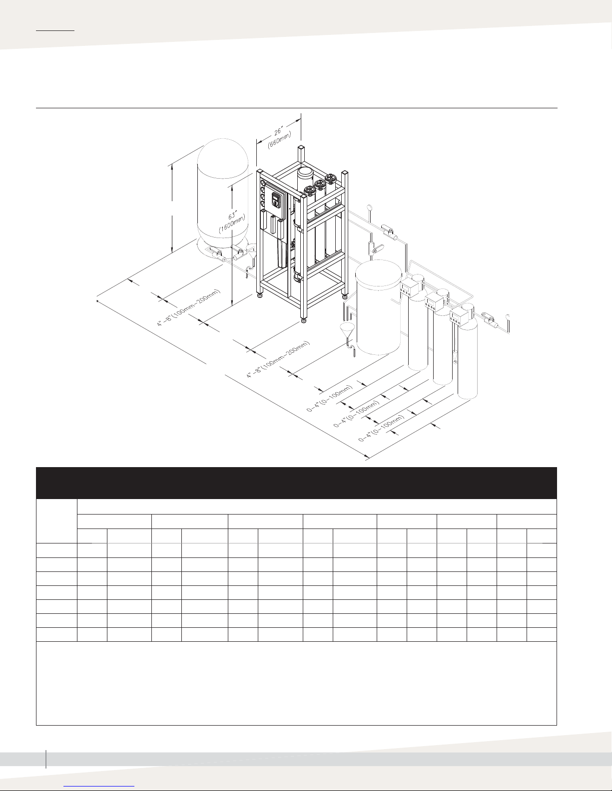
FIGURE 6-1: DRISTEEM 400 SERIES REVERSE-OSMOSIS SYSTEM OVERVIEW
B
C
D
A
E
Note: System components and confi guration
may vary to meet application requirements.
mc_032213_1030
F
F
G
OM-7816
Table 6-1:
DriSteem 400 series RO system dimensions
Model
inches mm inches mm inches mm inches mm inches mm inches mm inches mm
401 110 2794 55 1397 24 610 28 711 18 457 12 305 4
402 120 3048 55 1397 24 610 28 711 24 610 14 356 4
403 140 3556 55 610 24 610 28 711 24 610 16 406 16 406
404 140 3556 55 610 24 610 28 711 24 610 16 406 16 406
406 170 4318 80 2032 24 610 37 940 30 762 21 533 21 533
408 194 4928 72 1829 30 762 37 940 39 991 24 610 24 610
412 221.5 5626 90 2286 30 762 46.5 1181 39 991 30 762 30 762
2
A
BCDE1F
1
Dimension
1
G
3
3
1
102
102
Notes:
1. Water treatment component sizing is based on city-treated water, 20-grain hardness, and 50°F (10°C) or higher. City-treated water or well water
with different hardness or temperature may require different components/dimensions. Call DriSteem with your water characteristics for component
sizing.
2. Dimension given is maximum dimension when all components are located sequentially. Component locations are fl exible; components may be
placed in front of each other if fl oor space allows.
3. Wall-mounted dechlorinator.
mc_032213_0945
DRISTEEM WATER TREATMENT SYSTEMS INSTALLATION, OPERATION, AND MAINTENANCE MANUAL
6
System dimensions
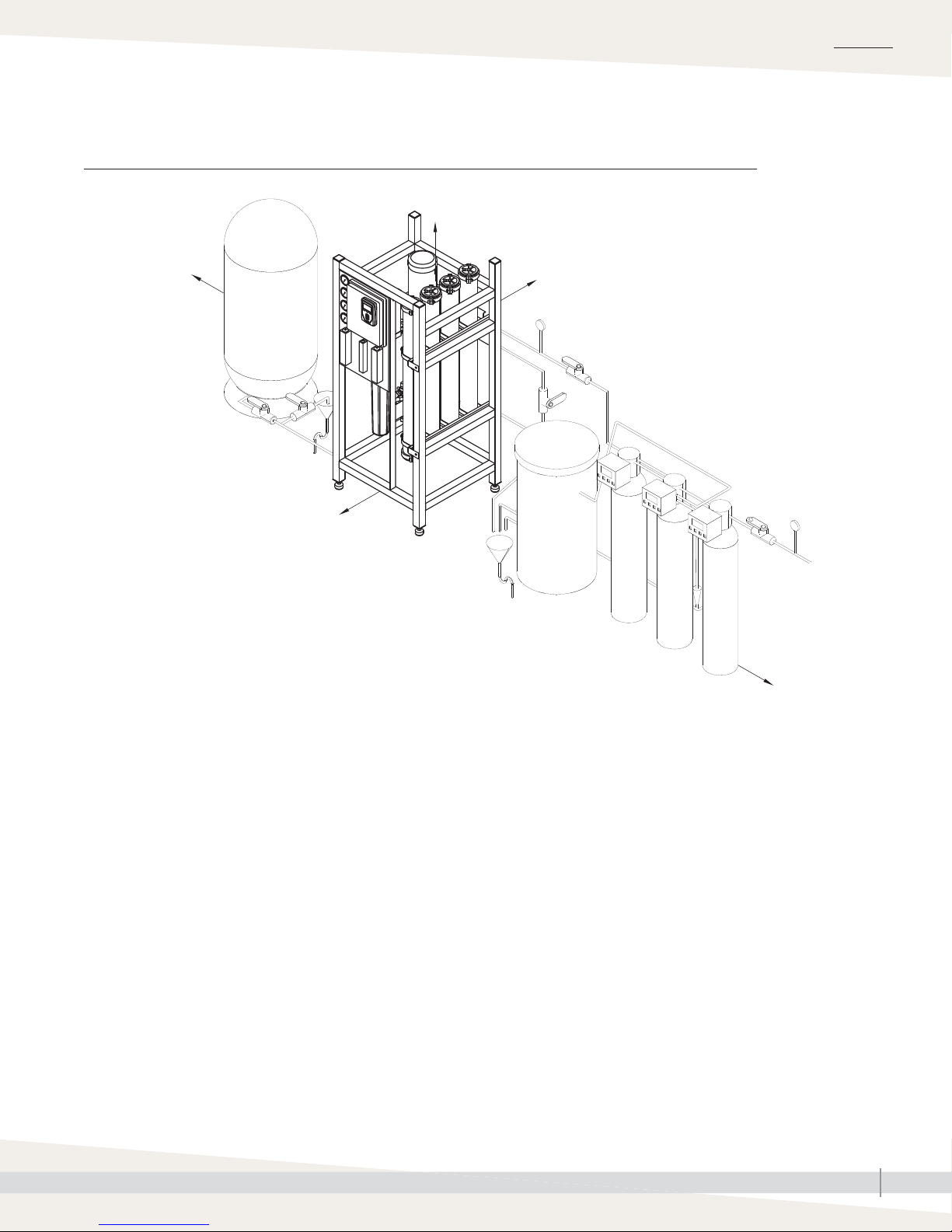
FIGURE 7-1: DRISTEEM 400 SERIES REVERSE-OSMOSIS SYSTEM CLEARANCES
48" (1220 mm)
8" (203 mm) 8" (203 mm)
OVERVIEW
36" (915 mm)
Note: See Figure 11-1 for recommended clearances.
mc_032213_0946
OM-7817
8" (203 mm)
DRISTEEM WATER TREATMENT SYSTEMS INSTALLATION, OPERATION, AND MAINTENANCE MANUAL
7

OVERVIEW
Water quality and component overview
WATER QUALITY
Supply water must be softened and dechlorinated before being supplied to the reverse-osmosis system. If water is not
properly dechlorinated or softened, it can damage reverse osmosis membranes. If you are not installing DriSteem water
pretreatment components, verify that your water has had chlorine removed and is softenened.
DECHLORINATOR REMOVES CHLORINE
The dechlorinator removes chlorine from supply water before it enters the reverse osmosis membranes.
Supply water enters the dechlorinator and passes through a charcoal sieve, which neutralizes chlorine before entering
the water softener. The dechlorinator is automatically backfl ushed whenever a programmed calendar date or water
meter usage is met. During automatic backfl ushing, clean water fl ows through the dechlorinator to rinse the charcoal,
and then fl ows to drain (tank dechlorinators only).
WATER SOFTENER REMOVES CALCIUM, MAGNESIUM, AND IRON
The water softener removes dissolved hard water minerals from supply water before it enters the reverse osmosis
membranes.
Water passes from the dechlorinator into the softener where dissolved minerals are removed by an ion-exchange
process. Softened water exits through a water meter to enter the reverse osmosis membranes. When the water meter
fl ow setpoint is satisfi ed, the softener will take brine from the brine tank to regenerate the resin. Water will be rejected to
drain during this period of rinsing.
REVERSE OSMOSIS MEMBRANES ELIMINATE REMAINING MINERALS AND
ORGANICS
CAUTION
Dissolved minerals and organics must be eliminated from the water in order to
keep system components operating properly. Potable water passes through a
dechlorinator and duplex water softener to take out chlorine and hard water
deposits. The softened water enters the RO station, then fl ows through a 5
micron fi lter cartridge. Thereafter, a multi-stage pump pressurizes the water to
Water supplied to the reverse-osmosis
system that does not meet the required
water quality standards will cause
premature component failure and void
the DriSteem warranty.
approximately 125 psig (860 kPa), depending on the quality of water and
the desired fl ow. Then, water is forced to cross a reverse-osmosis membrane,
which removes most dissolved minerals. The water is now purifi ed and contains
very few minerals (typically less than 10 ppm) and is then stored in the
pressurized storage tank. A portion of the rejection water may be recirculated;
the rest, which is saturated with minerals, is sent to the drain.
COMPONENT OVERVIEW
Your system may include all or some of the following components.
• Water pretreatment components
- Dechlorinator (tank style fl oor mount recommended on all sizes, cartridge style wall mount available for RO
models 401 and 402)
- Single or duplex water softener and brine tank
• RO storage options include:
- Pressurized RO holding tank
- Atmospheric RO holding tank with UV sterilization and booster pump
DRISTEEM WATER TREATMENT SYSTEMS INSTALLATION, OPERATION, AND MAINTENANCE MANUAL
8

Water quality and component overview
OVERVIEW
DESIGN BASIS
• Systems rated at: 50°F (10°C) using 1000 PPM sodium
chloride solution operating at 200 psi pressure.
• Minimum feed pressure to RO System: 40 PSI. System
capacity changes signifi cantly with water temperature. For
higher TDS a water analysis must be supplied and could
result in modifi cations to the system.
• Chlorine must be removed if present in feed water prior to
RO with a dechlorinator.
• Water must be pretreated with a softener to avoid scaling
the membranes.
• Feed water turbidity: Less than 1 NTU; Feed water
silt density index (SDI): 3 maximum. If exceeded,
pretreatment with media fi lter recommended. All
pretreatment equipment are available from DriSteem.
• Capacity Basis: 24 hrs/day
DESIGN NOTES
1. Pump flow/Feed flow: The pump has been designed to
include recycle flow (if any) coming back to the pump
inlet from the concentrate stream based on desired
recovery. The sum of permeate flow, concentrate flow
and recycle flow (if any) will equal the pump design
flow.
Important:
• System pressure is a variable. It is
important to adjust the pressure to get
the correct permeate and concentrate
flows. The exact value of the pressure
is not important.
• Permeate flow will increase at higher
temperature.
CAUTION
Damage to pump
Do not close the valve. Do not operate
the pump below minimum combined
fl ow rate (permeate + concentrate +
recirculating).
Models 401-402: 4 gpm (15.2 L/
min)
Models 403-412: 6 gpm (22.7 L/min)
2. Permeate flow: Indicates design flow rate from RO
membranes as product water for use.
3. Concentrate flow: Water flowing to the drain.
Concentrate flow is critical for proper system operation.
4. Recycle flow: Flow stream that returns from the
concentrate line back to the pump intake, rather than to
the drain.
DRISTEEM WATER TREATMENT SYSTEMS INSTALLATION, OPERATION, AND MAINTENANCE MANUAL
9

OVERVIEW
Components overview
REVERSE OSMOSIS STATION
The reverse-osmosis (RO) station is fl oor-mounted and removes approximately 98% of total dissolved solids.
Table 10-1:
400 series RO station specifications
Model 401 402 403 404 406 408 412
Permeate fl ow rate,
lbs/hr (kg/hr) or
GPD (LPD)
50 ºF (10 ºC)
Permeate fl ow rate,
lbs/hr (kg/hr) or
GPD (LPD)
77 ºF (25 ºC)
250 (113)
720 (2,725)
472 (214)
1,361 (5,152)
500 (227)
1,440 (5,451)
945 (429)
2,722 (10,304)
1,000 (454)
2,880 (10,902)
1,890 (857)
5,443 (20,604)
1,750 (794)
5,040 (19,078)
3,308 (1,500)
9,526 (36,060)
2,500 (1,134)
7,200 (27,255)
4,725 (2,143)
13,608 (51,512)
3,500 (1,588)
10,080 (38,157)
6,615 (3,000)
19,051 (72,116)
29,938 (113,327)
5,500 (2,495)
15,840 (59,961)
10,395 (4,715)
System voltage/phase,
Amp draw with RO
components
(see Note 1)
Fuse size with RO
components
(see Note 2)
Dimensions (W/D/H),
inches (mm)
Shipping weight, lbs (kg) 440 (200) 470 (213) 510 (231) 540 (245) 645 (293) 705 (320) 870 (395)
Supply water
connection dia., inches
(see Note 3)
RO system permeate
water outlet connection
dia., inches
Connection to
pressurized RO storage
tank dia., inches
Common drain outlet
connection dia., inches
5-micron RO prefi lter
diameter x height,
inches (mm)
480/3, 2.5
220/1, 10.0
120/1, 19.2
480/3, 15
220/1, 15
120/1, 25
28/26/63
(711/660/1600)
¾" hose barb ¾" hose barb ¾" hose barb ¾" hose barb ¾" hose barb ¾" hose barb ¾" hose barb
¾" hose barb ¾" hose barb ¾" hose barb ¾" hose barb ¾" hose barb ¾" hose barb ¾" hose barb
111 1 1 1 1
1" hose barb 1" hose barb 1" hose barb 1" hose barb 1" hose barb 1" hose barb 1" hose barb
2.5 × 20
(64 x 508)
480/3, 2.5
220/1, 10.0
120/1, 19.2
480/3, 15
220/1, 15
120/1, 25
28/26/63
(711/660/1600)
2.5 × 20
(64 x 508)
480/3, 6.0
220/1, 15.4
480/3, 15
220/1, 20
28/26/63
(711/660/1600)
2.5 × 20
(64 x 508)
480/3, 6.0
220/1, 15.4
480/3, 15
220/1, 20
28/26/63
(711/660/1600)
2.5 × 20
(64 x 508)
480/3, 6.0
220/1, 15.4
480/3, 15
220/1, 20
37/26/63
(940/660/1600)
4 × 20
(102 x 508)
480/3, 6.0
220/1, 15.4
480/3, 15
220/1, 20
37/26/63
(940/660/1600)
4 × 20
(102 x 508)
480/3, 6.0
220/1, 15.4
480/3, 15
220/1, 20
46½/26/63
(1181/660/1600)
4 × 20
(102 x 508)
RO pump motor power,
hp (kW)
Qty. of RO membranes 1 2 3 4 6 8 12
RO membrane
diameter x height,
inches (mm)
Notes:
1. 220V/1-phase systems can also operate on 208V/1-phase and 240V/1-phase power.
2. Wiring and branch circuit protection (Type RK1, J, or T fusing) to be provided by installer in accordance with NEC requirements.
3. 40 psi (280 kPa) minimum supply water pressure.
mc_032213_1006
DRISTEEM WATER TREATMENT SYSTEMS INSTALLATION, OPERATION, AND MAINTENANCE MANUAL
10
1
(0.75)
4 × 40
(102 x 1016)
(0.75)
4 × 40
(102 x 1016)
1
3
(2.2)
4 × 40
(102 x 1016)
3
(2.2)
4 × 40
(102 x 1016)
3
(2.2)
4 × 40
(102 x 1016)
3
(2.2)
4 × 40
(102 x 1016)
3
(2.2)
4 × 40
(102 x 1016)
Components overview
OVERVIEW
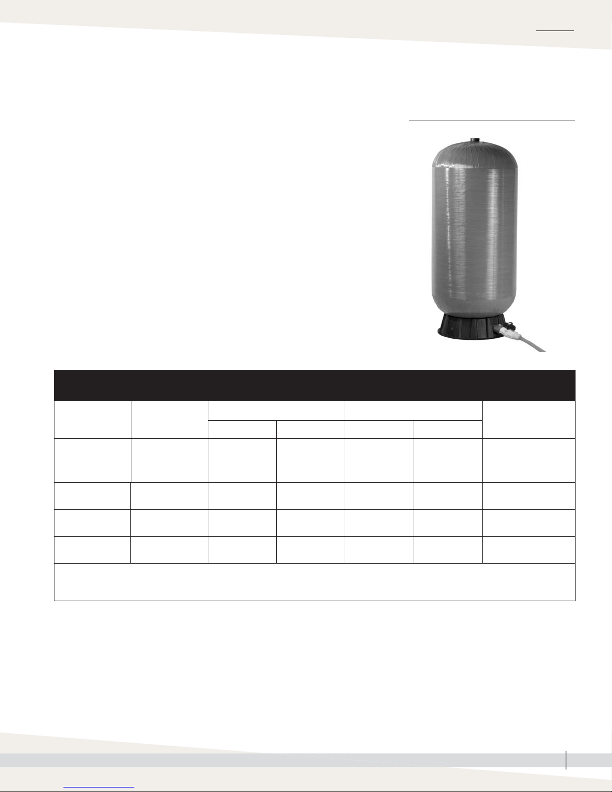
PRESSURIZED RO HOLDING TANK
The pressurized RO holding tank holds RO water in reserve to be available for
high-pressure pumping when there is a demand.
Table 11-1:
Pressurized RO holding tank specifications
FIGURE 11-1: PRESSURIZED RO
HOLDING TANK
Model RO station model
401
402
403
404
406
408
412
Notes:
• There is a possibility that the tank becomes much heavier if the air balloon is emptied or if precharge is different than 28 psi (195 kPa).
• Listed water volumes and weights are at an operating pressure of 30 to 50 psi (210 to 345 kPa) with a precharge of 28 psi (195 kPa).
mc_032213_1045
80 gal
(303 L)
120 gal
(454 L)
158 gal
(598 L)
211 gal
(799 L)
Diameter Height Empty Full
(610 mm)
(610 mm)
(762 mm)
(762 mm)
Dimensions Weight
24"
24"
30"
30"
55.5"
(1410 mm)
66
(1676 mm)
58
(1473 mm)
76
(1930 mm)
58 lbs
(26 kg)
335 lbs
(152 kg)
435 lbs
(197 kg)
515 lbs
(234 kg)
295 lbs
(134 kg)
1235 lbs
(560 kg)
1620 lbs
(735 kg)
2100 lbs
(953 kg)
Connections
1¼" male NPT
2" female NPT
2" female NPT
2" female NPT
DRISTEEM WATER TREATMENT SYSTEMS INSTALLATION, OPERATION, AND MAINTENANCE MANUAL
11
OVERVIEW
Components overview
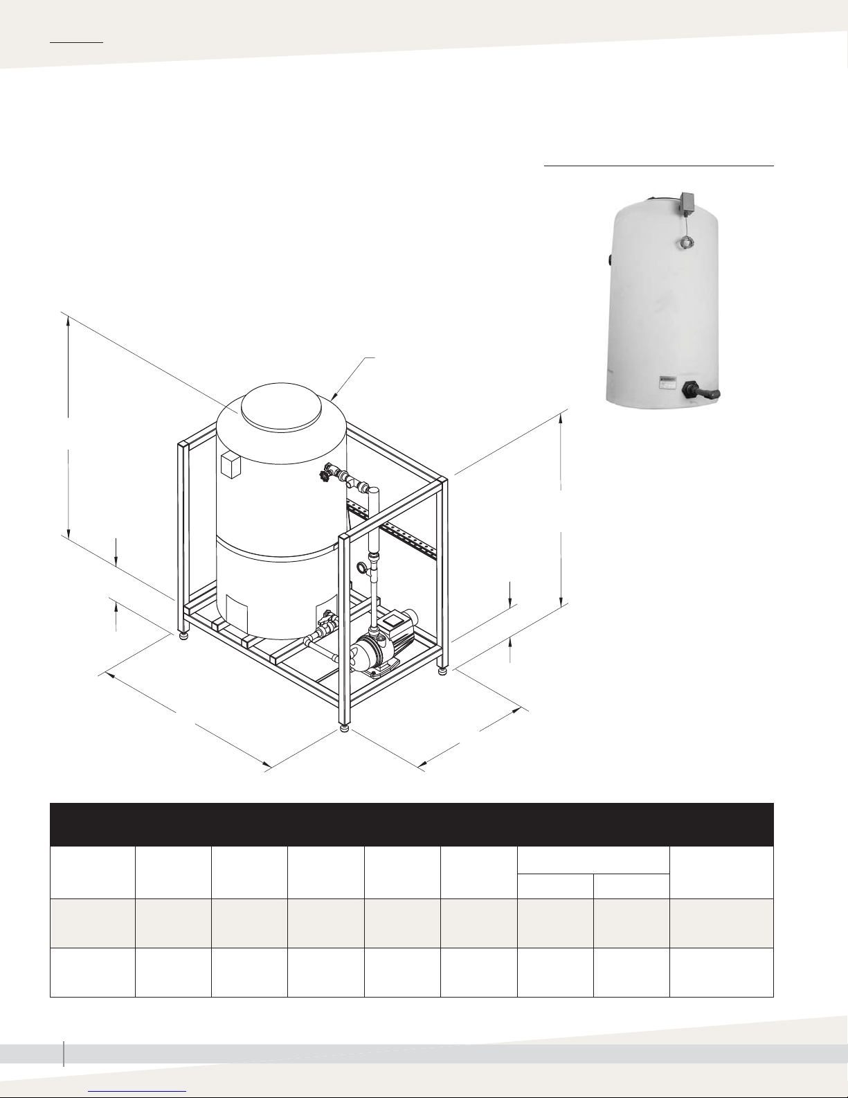
ATMOSPHERIC RO HOLDING TANK
The atmospheric RO hold tank holds a large amount of RO water for large
jobs or when additional runtime needs to be guaranteed. System includes a
recirculation/booster pump and an UV sterilization system to ensure water
purity and supply 30-50 psi (207-345 kPa) water to downstream equipment.
D
C
FIGURE 12-1: ATMOSPHERIC RO
HOLDING TANK
56" (1422 mm)
10" (254 mm)
A
Table 12-1:
Atmospheric RO holding tank specifications
RO station
model
AT-165
AT-300
Description A B C D
165 gal
(567 L)
300 gal
(1135 L)
56"
(1422 mm)
60.5"
(1536.7 mm)
(1003 mm)
35"
(889 mm)
39.5"
51"
(1295 mm)
77"
(1955.8 mm)
8" (203 mm)
B
31"
(787 mm)
35.5"
(901.7 mm)
OM-7820
Weight
Shipping Operating
320 lbs
(145.15 kg)
360 lbs
(163.3 kg)
1695 lbs
(768.84 kg)
2860 lbs
(1297.27 kg)
Connections
1" (25 mm) PVC
1" (25 mm) PVC
mc_032213_1045
DRISTEEM WATER TREATMENT SYSTEMS INSTALLATION, OPERATION, AND MAINTENANCE MANUAL
12

Placing components
OVERVIEW
When placing components, consider the following:
• Easy access for maintenance
• Select a location near a water supply, power supply, and drain.
• Minimize distance between the RO station and the equipment using the RO
water.
• Maximum ambient temperature is 104°F (40°C).
Minimum ambient temperature is 40°F (4.4°C)
• Clearance recommendations (see Figure 7-1).
• Electrical connections: Power, control, and safety circuits
• Plumbing connections: Supply water and drain piping (see the “System
piping” section of this manual, beginning on Page18.
• Avoid locations above critical equipment or processes.
• Avoid locations close to sources of electromagnetic emissions, such as
power distribution transformers and high horsepower motors controlled by
variable frequency drives.
Important:
Installation must comply with governing codes.
WARNING
All DriSteem RO-400 series reverseosmosis systems must be bolted to the
fl oor or permanently attached to the
building structure. Use the shipping
brackets that come with the system to
anchor the system to the fl oor or use
the attachment points on the underside
of the top frame rail on the back of
the system to secure the system to the
building structure. Ensure adequate
anchors and/retaining means are
used. Failure to install according to
instructions can result in serious injury
or death.
DRISTEEM WATER TREATMENT SYSTEMS INSTALLATION, OPERATION, AND MAINTENANCE MANUAL
13
INSTALLATION
p
p
”
p
”
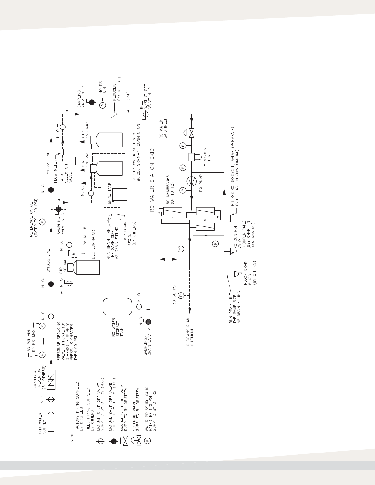
Piping and instrumentation arrangement
FIGURE 14-1: FLOW SCHEMATIC WITH A TANK DECHLORINATOR
to 2
u
to 2
u
to 2”
u
DRISTEEM WATER TREATMENT SYSTEMS INSTALLATION, OPERATION, AND MAINTENANCE MANUAL
14
OM-7828
 Loading...