

Page 1
READ AND SAVE THESE INSTRUCTIONS
WATER TREATMENT
400 series
reverse-osmosis systems
Installation, Operation,
and Maintenance Manual
Page 2

DRISTEEM WATER TREATMENT SYSTEMS INSTALLATION, OPERATION, AND MAINTENANCE MANUAL
ii
Page 3
Warnings and cautions
WARNING
Attention installer
Read this manual before installing, and leave this manual with product owner. This product must be installed by qualifi ed
plumbing, HVAC and/or electrical contractors. Installation must be code approved.
Disconnect electrical power
Disconnect electrical power before installing supply wiring or performing service or maintenance procedures on any part
of the system. Failure to disconnect electrical power could result in fi re, electrical shock, and other hazardous conditions.
These hazardous conditions could cause property damage, personal injury, or death.
Contact with energized circuits can cause property damage, severe personal injury, or death as a result of electrical shock
or fi re. Do not remove pump cover, or subpanel access panels until electrical power is disconnected.
Follow the shutdown procedure in this manual before performing service or maintenance procedures on any part of the
system.
mc_052410_1510
Electric shock hazard
If the reverse-osmosis system starts up during maintenance, severe bodily injury or death from electric shock could occur.
To prevent such start-up, follow the procedure below before performing service or maintenance procedures on this reverseosmosis system:
1. Use Vapor-logic
2. Shut off all electrical power to the reverse-osmosis system using fi eld-installed fused disconnect, and lock all power
disconnect switches in OFF position.
3. Close fi eld-installed manual water supply shut-off valve.
mc_050808_1540
Tipping hazard
Before installing the 400 series reverse-osmosis system, use supplied leg brackets or lag points to permanently fi x the
system to the fl oor and/or adjacent building structure. Failure to install according to instructions can result in serious injury
or death. See page 13 for instructions.
®
keypad/display to change control mode to Standby.
WARNINGS AND CAUTIONS
Team lift required
Team lift is required when replacing the membranes. Membrane banks are heavy. Do not try to lift without assistance.
Wear steel-toed shoes and have adequate room for maneuvering when servicing. Never lean membrane banks vertically
when removed from system. Failure to do so may damage the system or result in injury. See maintenance information on
page 38.
DRISTEEM WATER TREATMENT SYSTEMS INSTALLATION, OPERATION, AND MAINTENANCE MANUAL
iii
Page 4

WARNINGS AND CAUTIONS
Warnings and cautions
CAUTION
Operate system at above-freezing temperatures.
Operating the system at temperatures below freezing can damage the system or cause other property damage.
Maintain pumping and water treatment equipment.
Inadequately maintained pumping and water treatment equipment can cause the system to fail. Refer to the maintenance section
of this IOM for recommended maintenance.
Do not install the system using steel or galvanized-steel piping and joints.
Steel and steel-galvanized piping and joints can corrode and cause system damage. Use PVC or stainless steel piping and joints
when assembling system.
Follow all instructions in this manual to maintain product warranty.
Damage to pump
Do not close the valve on the outlet of the pump. Do not operate the pump below minimum combined fl ow rate (permeate +
concentrate + recirculating).
Models 401-402: 4 gpm (15.2 L/min)
Models 403-412: 6 gpm (22.7 L/min)
DRISTEEM WATER TREATMENT SYSTEMS INSTALLATION, OPERATION, AND MAINTENANCE MANUAL
iv
Page 5

Table of contents
WARNINGS AND CAUTIONS . . . . . . . . . . . . . . . . . . . . . . . . . . . . . . . . . . . . . . . . . . . . . . . iii
OVERVIEW. . . . . . . . . . . . . . . . . . . . . . . . . . . . . . . . . . . . . . . . . . . . . . . . . . . . . . . . . . . . . . 6
System dimensions . . . . . . . . . . . . . . . . . . . . . . . . . . . . . . . . . . . . . . 7
Water quality and component overview . . . . . . . . . . . . . . . . . . . . . . . 8
Reverse osmosis station . . . . . . . . . . . . . . . . . . . . . . . . . . . . . . 10
Pressurized RO holding tank . . . . . . . . . . . . . . . . . . . . . . . . . . .11
Atmospheric RO holding tank . . . . . . . . . . . . . . . . . . . . . . . . . . 12
Placing components . . . . . . . . . . . . . . . . . . . . . . . . . . . . . . . . . . . .13
INSTALLATION . . . . . . . . . . . . . . . . . . . . . . . . . . . . . . . . . . . . . . . . . . . . . . . . . . . . . . . . . 14
Piping and instrumentation arrangement . . . . . . . . . . . . . . . . . . . . . 14
Interconnecting tubing requirements . . . . . . . . . . . . . . . . . . . . . . . . .16
Components and tools needed . . . . . . . . . . . . . . . . . . . . . . . . . . . . 17
System piping . . . . . . . . . . . . . . . . . . . . . . . . . . . . . . . . . . . . . . . . 18
Water pre-treatment . . . . . . . . . . . . . . . . . . . . . . . . . . . . . . . . .18
Dechlorinator . . . . . . . . . . . . . . . . . . . . . . . . . . . . . . . . . . . . . 18
Duplex water softener . . . . . . . . . . . . . . . . . . . . . . . . . . . . . . . 18
RO station and pressurized RO holding tank . . . . . . . . . . . . . . . 19
Wiring . . . . . . . . . . . . . . . . . . . . . . . . . . . . . . . . . . . . . . . . . . 21
Electrical installation . . . . . . . . . . . . . . . . . . . . . . . . . . . . . . . . 21
Service disconnect . . . . . . . . . . . . . . . . . . . . . . . . . . . . . . . . . . 21
Preventing electrical noise . . . . . . . . . . . . . . . . . . . . . . . . . . . . .21
Grounding requirements . . . . . . . . . . . . . . . . . . . . . . . . . . . . . .22
Start-up checklist . . . . . . . . . . . . . . . . . . . . . . . . . . . . . . . . . . . . . . 23
ATTENTION INSTALLER
Read this manual before installing.
Leave manual with product owner.
DriSteem® Technical Support
800-328-4447
WHERE TO FIND MORE INFORMATION
Our website:
The following document is available on our
web site: www.dristeem.com
• Water treatment system catalog
• Vapor-logic controller installation and
operation manual
DriCalc®:
DriCalc, our software for system sizing and
selection, can be ordered at our web site.
Call us at 800-328-4447
Obtaining documents from our web site or
from DriCalc is the quickest way to view our
literature, or we will be happy to mail literature
to you.
OPERATION . . . . . . . . . . . . . . . . . . . . . . . . . . . . . . . . . . . . . . . . . . . . . . . . . . . . . . . . . . . 23
Start-up . . . . . . . . . . . . . . . . . . . . . . . . . . . . . . . . . . . . . . . . . . . . 24
Start-up procedure . . . . . . . . . . . . . . . . . . . . . . . . . . . . . . . . . . 24
Test operation . . . . . . . . . . . . . . . . . . . . . . . . . . . . . . . . . . . . . 24
System operation . . . . . . . . . . . . . . . . . . . . . . . . . . . . . . . . . . . . . . 26
Vapor-logic keypad/display . . . . . . . . . . . . . . . . . . . . . . . . . . . . . .27
Status screen . . . . . . . . . . . . . . . . . . . . . . . . . . . . . . . . . . . . . . 29
Diagonstics and Alarms . . . . . . . . . . . . . . . . . . . . . . . . . . . . . . . . . 30
Modbus, BACnet, LonTalk interoperability . . . . . . . . . . . . . . . . . . . . 31
MAINTENANCE . . . . . . . . . . . . . . . . . . . . . . . . . . . . . . . . . . . . . . . . . . . . . . . . . . . . . . . . 33
When to change sediment prefilter cartridge . . . . . . . . . . . . . . .34
Changing cartridge filters . . . . . . . . . . . . . . . . . . . . . . . . . . . . .34
Preserving procedure . . . . . . . . . . . . . . . . . . . . . . . . . . . . . . . . 37
Flushing out preservative/restart procedure . . . . . . . . . . . . . . . .37
Tools . . . . . . . . . . . . . . . . . . . . . . . . . . . . . . . . . . . . . . . . . . . 38
Gauges and valves . . . . . . . . . . . . . . . . . . . . . . . . . . . . . . . . . 39
Dechlorinator . . . . . . . . . . . . . . . . . . . . . . . . . . . . . . . . . . . . . 39
Water softener . . . . . . . . . . . . . . . . . . . . . . . . . . . . . . . . . . . . 39
Pressurized RO holding tank . . . . . . . . . . . . . . . . . . . . . . . . . . .39
Troubleshooting . . . . . . . . . . . . . . . . . . . . . . . . . . . . . . . . . . . . . . . 40
System operation temperature . . . . . . . . . . . . . . . . . . . . . . . . . . . . . 43
WARRANTY . . . . . . . . . . . . . . . . . . . . . . . . . . . . . . . . . . . . . . . . . . . . . . . . . . . . . . . . . . . 46
Keypad/display and troubleshooting
The Vapor-logic Installation and Operation
Manual, which was shipped with the system, is
a comprehensive operation manual. Refer to it
for information about using the keypad/display
and Web interface, and for troubleshooting
information.
Download DriSteem literature
Most DriSteem product manuals are available
our website: www.dristeem.com
DRISTEEM WATER TREATMENT SYSTEMS INSTALLATION, OPERATION, AND MAINTENANCE MANUAL
v
Page 6
OVERVIEW
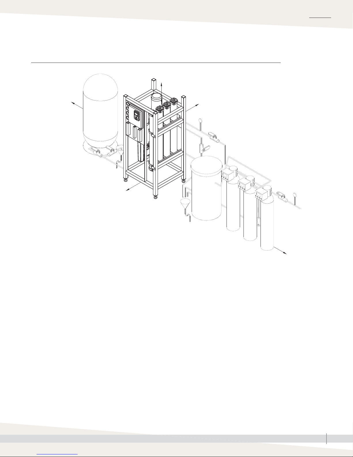
System overview
FIGURE 6-1: DRISTEEM 400 SERIES REVERSE-OSMOSIS SYSTEM OVERVIEW
B
C
D
A
E
Note: System components and confi guration
may vary to meet application requirements.
mc_032213_1030
F
F
G
OM-7816
Table 6-1:
DriSteem 400 series RO system dimensions
Model
inches mm inches mm inches mm inches mm inches mm inches mm inches mm
401 110 2794 55 1397 24 610 28 711 18 457 12 305 4
402 120 3048 55 1397 24 610 28 711 24 610 14 356 4
403 140 3556 55 610 24 610 28 711 24 610 16 406 16 406
404 140 3556 55 610 24 610 28 711 24 610 16 406 16 406
406 170 4318 80 2032 24 610 37 940 30 762 21 533 21 533
408 194 4928 72 1829 30 762 37 940 39 991 24 610 24 610
412 221.5 5626 90 2286 30 762 46.5 1181 39 991 30 762 30 762
2
A
BCDE1F
1
Dimension
1
G
3
3
1
102
102
Notes:
1. Water treatment component sizing is based on city-treated water, 20-grain hardness, and 50°F (10°C) or higher. City-treated water or well water
with different hardness or temperature may require different components/dimensions. Call DriSteem with your water characteristics for component
sizing.
2. Dimension given is maximum dimension when all components are located sequentially. Component locations are fl exible; components may be
placed in front of each other if fl oor space allows.
3. Wall-mounted dechlorinator.
mc_032213_0945
DRISTEEM WATER TREATMENT SYSTEMS INSTALLATION, OPERATION, AND MAINTENANCE MANUAL
6
Page 7
System dimensions
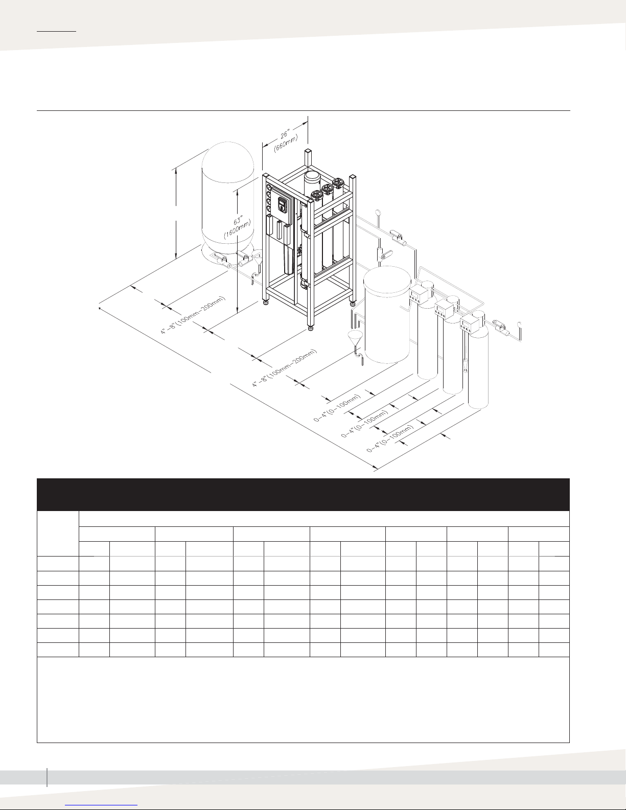
FIGURE 7-1: DRISTEEM 400 SERIES REVERSE-OSMOSIS SYSTEM CLEARANCES
48" (1220 mm)
8" (203 mm) 8" (203 mm)
OVERVIEW
36" (915 mm)
Note: See Figure 11-1 for recommended clearances.
mc_032213_0946
OM-7817
8" (203 mm)
DRISTEEM WATER TREATMENT SYSTEMS INSTALLATION, OPERATION, AND MAINTENANCE MANUAL
7
Page 8

OVERVIEW
Water quality and component overview
WATER QUALITY
Supply water must be softened and dechlorinated before being supplied to the reverse-osmosis system. If water is not
properly dechlorinated or softened, it can damage reverse osmosis membranes. If you are not installing DriSteem water
pretreatment components, verify that your water has had chlorine removed and is softenened.
DECHLORINATOR REMOVES CHLORINE
The dechlorinator removes chlorine from supply water before it enters the reverse osmosis membranes.
Supply water enters the dechlorinator and passes through a charcoal sieve, which neutralizes chlorine before entering
the water softener. The dechlorinator is automatically backfl ushed whenever a programmed calendar date or water
meter usage is met. During automatic backfl ushing, clean water fl ows through the dechlorinator to rinse the charcoal,
and then fl ows to drain (tank dechlorinators only).
WATER SOFTENER REMOVES CALCIUM, MAGNESIUM, AND IRON
The water softener removes dissolved hard water minerals from supply water before it enters the reverse osmosis
membranes.
Water passes from the dechlorinator into the softener where dissolved minerals are removed by an ion-exchange
process. Softened water exits through a water meter to enter the reverse osmosis membranes. When the water meter
fl ow setpoint is satisfi ed, the softener will take brine from the brine tank to regenerate the resin. Water will be rejected to
drain during this period of rinsing.
REVERSE OSMOSIS MEMBRANES ELIMINATE REMAINING MINERALS AND
ORGANICS
CAUTION
Dissolved minerals and organics must be eliminated from the water in order to
keep system components operating properly. Potable water passes through a
dechlorinator and duplex water softener to take out chlorine and hard water
deposits. The softened water enters the RO station, then fl ows through a 5
micron fi lter cartridge. Thereafter, a multi-stage pump pressurizes the water to
Water supplied to the reverse-osmosis
system that does not meet the required
water quality standards will cause
premature component failure and void
the DriSteem warranty.
approximately 125 psig (860 kPa), depending on the quality of water and
the desired fl ow. Then, water is forced to cross a reverse-osmosis membrane,
which removes most dissolved minerals. The water is now purifi ed and contains
very few minerals (typically less than 10 ppm) and is then stored in the
pressurized storage tank. A portion of the rejection water may be recirculated;
the rest, which is saturated with minerals, is sent to the drain.
COMPONENT OVERVIEW
Your system may include all or some of the following components.
• Water pretreatment components
- Dechlorinator (tank style fl oor mount recommended on all sizes, cartridge style wall mount available for RO
models 401 and 402)
- Single or duplex water softener and brine tank
• RO storage options include:
- Pressurized RO holding tank
- Atmospheric RO holding tank with UV sterilization and booster pump
DRISTEEM WATER TREATMENT SYSTEMS INSTALLATION, OPERATION, AND MAINTENANCE MANUAL
8
Page 9

Water quality and component overview
OVERVIEW
DESIGN BASIS
• Systems rated at: 50°F (10°C) using 1000 PPM sodium
chloride solution operating at 200 psi pressure.
• Minimum feed pressure to RO System: 40 PSI. System
capacity changes signifi cantly with water temperature. For
higher TDS a water analysis must be supplied and could
result in modifi cations to the system.
• Chlorine must be removed if present in feed water prior to
RO with a dechlorinator.
• Water must be pretreated with a softener to avoid scaling
the membranes.
• Feed water turbidity: Less than 1 NTU; Feed water
silt density index (SDI): 3 maximum. If exceeded,
pretreatment with media fi lter recommended. All
pretreatment equipment are available from DriSteem.
• Capacity Basis: 24 hrs/day
DESIGN NOTES
1. Pump flow/Feed flow: The pump has been designed to
include recycle flow (if any) coming back to the pump
inlet from the concentrate stream based on desired
recovery. The sum of permeate flow, concentrate flow
and recycle flow (if any) will equal the pump design
flow.
Important:
• System pressure is a variable. It is
important to adjust the pressure to get
the correct permeate and concentrate
flows. The exact value of the pressure
is not important.
• Permeate flow will increase at higher
temperature.
CAUTION
Damage to pump
Do not close the valve. Do not operate
the pump below minimum combined
fl ow rate (permeate + concentrate +
recirculating).
Models 401-402: 4 gpm (15.2 L/
min)
Models 403-412: 6 gpm (22.7 L/min)
2. Permeate flow: Indicates design flow rate from RO
membranes as product water for use.
3. Concentrate flow: Water flowing to the drain.
Concentrate flow is critical for proper system operation.
4. Recycle flow: Flow stream that returns from the
concentrate line back to the pump intake, rather than to
the drain.
DRISTEEM WATER TREATMENT SYSTEMS INSTALLATION, OPERATION, AND MAINTENANCE MANUAL
9
Page 10

OVERVIEW
Components overview
REVERSE OSMOSIS STATION
The reverse-osmosis (RO) station is fl oor-mounted and removes approximately 98% of total dissolved solids.
Table 10-1:
400 series RO station specifications
Model 401 402 403 404 406 408 412
Permeate fl ow rate,
lbs/hr (kg/hr) or
GPD (LPD)
50 ºF (10 ºC)
Permeate fl ow rate,
lbs/hr (kg/hr) or
GPD (LPD)
77 ºF (25 ºC)
250 (113)
720 (2,725)
472 (214)
1,361 (5,152)
500 (227)
1,440 (5,451)
945 (429)
2,722 (10,304)
1,000 (454)
2,880 (10,902)
1,890 (857)
5,443 (20,604)
1,750 (794)
5,040 (19,078)
3,308 (1,500)
9,526 (36,060)
2,500 (1,134)
7,200 (27,255)
4,725 (2,143)
13,608 (51,512)
3,500 (1,588)
10,080 (38,157)
6,615 (3,000)
19,051 (72,116)
29,938 (113,327)
5,500 (2,495)
15,840 (59,961)
10,395 (4,715)
System voltage/phase,
Amp draw with RO
components
(see Note 1)
Fuse size with RO
components
(see Note 2)
Dimensions (W/D/H),
inches (mm)
Shipping weight, lbs (kg) 440 (200) 470 (213) 510 (231) 540 (245) 645 (293) 705 (320) 870 (395)
Supply water
connection dia., inches
(see Note 3)
RO system permeate
water outlet connection
dia., inches
Connection to
pressurized RO storage
tank dia., inches
Common drain outlet
connection dia., inches
5-micron RO prefi lter
diameter x height,
inches (mm)
480/3, 2.5
220/1, 10.0
120/1, 19.2
480/3, 15
220/1, 15
120/1, 25
28/26/63
(711/660/1600)
¾" hose barb ¾" hose barb ¾" hose barb ¾" hose barb ¾" hose barb ¾" hose barb ¾" hose barb
¾" hose barb ¾" hose barb ¾" hose barb ¾" hose barb ¾" hose barb ¾" hose barb ¾" hose barb
111 1 1 1 1
1" hose barb 1" hose barb 1" hose barb 1" hose barb 1" hose barb 1" hose barb 1" hose barb
2.5 × 20
(64 x 508)
480/3, 2.5
220/1, 10.0
120/1, 19.2
480/3, 15
220/1, 15
120/1, 25
28/26/63
(711/660/1600)
2.5 × 20
(64 x 508)
480/3, 6.0
220/1, 15.4
480/3, 15
220/1, 20
28/26/63
(711/660/1600)
2.5 × 20
(64 x 508)
480/3, 6.0
220/1, 15.4
480/3, 15
220/1, 20
28/26/63
(711/660/1600)
2.5 × 20
(64 x 508)
480/3, 6.0
220/1, 15.4
480/3, 15
220/1, 20
37/26/63
(940/660/1600)
4 × 20
(102 x 508)
480/3, 6.0
220/1, 15.4
480/3, 15
220/1, 20
37/26/63
(940/660/1600)
4 × 20
(102 x 508)
480/3, 6.0
220/1, 15.4
480/3, 15
220/1, 20
46½/26/63
(1181/660/1600)
4 × 20
(102 x 508)
RO pump motor power,
hp (kW)
Qty. of RO membranes 1 2 3 4 6 8 12
RO membrane
diameter x height,
inches (mm)
Notes:
1. 220V/1-phase systems can also operate on 208V/1-phase and 240V/1-phase power.
2. Wiring and branch circuit protection (Type RK1, J, or T fusing) to be provided by installer in accordance with NEC requirements.
3. 40 psi (280 kPa) minimum supply water pressure.
mc_032213_1006
DRISTEEM WATER TREATMENT SYSTEMS INSTALLATION, OPERATION, AND MAINTENANCE MANUAL
10
1
(0.75)
4 × 40
(102 x 1016)
(0.75)
4 × 40
(102 x 1016)
1
3
(2.2)
4 × 40
(102 x 1016)
3
(2.2)
4 × 40
(102 x 1016)
3
(2.2)
4 × 40
(102 x 1016)
3
(2.2)
4 × 40
(102 x 1016)
3
(2.2)
4 × 40
(102 x 1016)
Page 11
Components overview
OVERVIEW
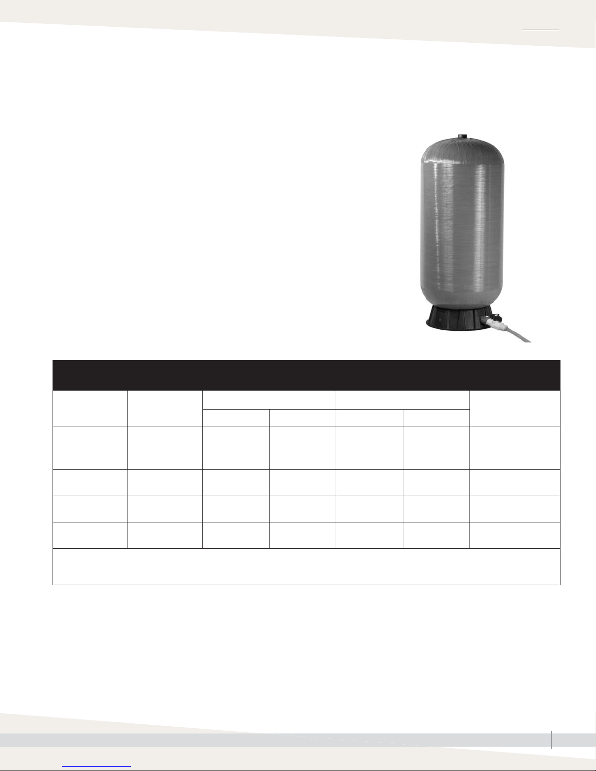
PRESSURIZED RO HOLDING TANK
The pressurized RO holding tank holds RO water in reserve to be available for
high-pressure pumping when there is a demand.
Table 11-1:
Pressurized RO holding tank specifications
FIGURE 11-1: PRESSURIZED RO
HOLDING TANK
Model RO station model
401
402
403
404
406
408
412
Notes:
• There is a possibility that the tank becomes much heavier if the air balloon is emptied or if precharge is different than 28 psi (195 kPa).
• Listed water volumes and weights are at an operating pressure of 30 to 50 psi (210 to 345 kPa) with a precharge of 28 psi (195 kPa).
mc_032213_1045
80 gal
(303 L)
120 gal
(454 L)
158 gal
(598 L)
211 gal
(799 L)
Diameter Height Empty Full
(610 mm)
(610 mm)
(762 mm)
(762 mm)
Dimensions Weight
24"
24"
30"
30"
55.5"
(1410 mm)
66
(1676 mm)
58
(1473 mm)
76
(1930 mm)
58 lbs
(26 kg)
335 lbs
(152 kg)
435 lbs
(197 kg)
515 lbs
(234 kg)
295 lbs
(134 kg)
1235 lbs
(560 kg)
1620 lbs
(735 kg)
2100 lbs
(953 kg)
Connections
1¼" male NPT
2" female NPT
2" female NPT
2" female NPT
DRISTEEM WATER TREATMENT SYSTEMS INSTALLATION, OPERATION, AND MAINTENANCE MANUAL
11
Page 12
OVERVIEW
Components overview
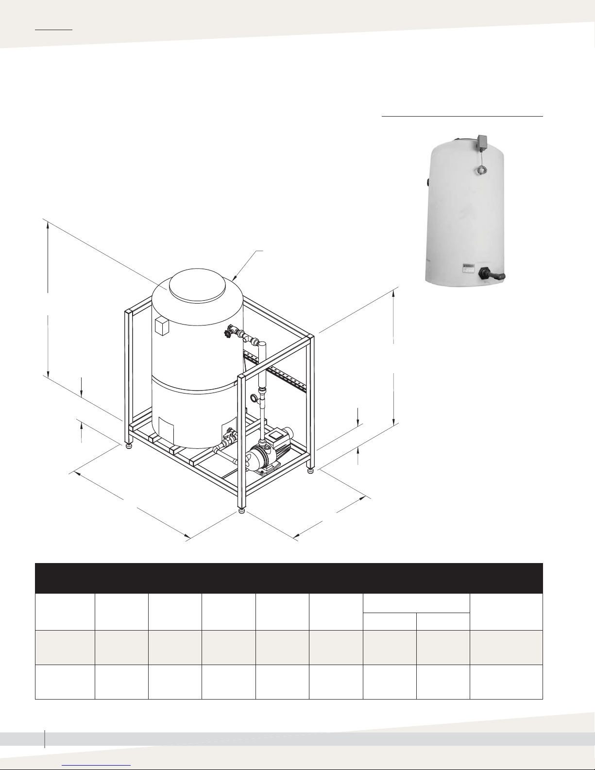
ATMOSPHERIC RO HOLDING TANK
The atmospheric RO hold tank holds a large amount of RO water for large
jobs or when additional runtime needs to be guaranteed. System includes a
recirculation/booster pump and an UV sterilization system to ensure water
purity and supply 30-50 psi (207-345 kPa) water to downstream equipment.
D
C
FIGURE 12-1: ATMOSPHERIC RO
HOLDING TANK
56" (1422 mm)
10" (254 mm)
A
Table 12-1:
Atmospheric RO holding tank specifications
RO station
model
AT-165
AT-300
Description A B C D
165 gal
(567 L)
300 gal
(1135 L)
56"
(1422 mm)
60.5"
(1536.7 mm)
(1003 mm)
35"
(889 mm)
39.5"
51"
(1295 mm)
77"
(1955.8 mm)
8" (203 mm)
B
31"
(787 mm)
35.5"
(901.7 mm)
OM-7820
Weight
Shipping Operating
320 lbs
(145.15 kg)
360 lbs
(163.3 kg)
1695 lbs
(768.84 kg)
2860 lbs
(1297.27 kg)
Connections
1" (25 mm) PVC
1" (25 mm) PVC
mc_032213_1045
DRISTEEM WATER TREATMENT SYSTEMS INSTALLATION, OPERATION, AND MAINTENANCE MANUAL
12
Page 13

Placing components
OVERVIEW
When placing components, consider the following:
• Easy access for maintenance
• Select a location near a water supply, power supply, and drain.
• Minimize distance between the RO station and the equipment using the RO
water.
• Maximum ambient temperature is 104°F (40°C).
Minimum ambient temperature is 40°F (4.4°C)
• Clearance recommendations (see Figure 7-1).
• Electrical connections: Power, control, and safety circuits
• Plumbing connections: Supply water and drain piping (see the “System
piping” section of this manual, beginning on Page18.
• Avoid locations above critical equipment or processes.
• Avoid locations close to sources of electromagnetic emissions, such as
power distribution transformers and high horsepower motors controlled by
variable frequency drives.
Important:
Installation must comply with governing codes.
WARNING
All DriSteem RO-400 series reverseosmosis systems must be bolted to the
fl oor or permanently attached to the
building structure. Use the shipping
brackets that come with the system to
anchor the system to the fl oor or use
the attachment points on the underside
of the top frame rail on the back of
the system to secure the system to the
building structure. Ensure adequate
anchors and/retaining means are
used. Failure to install according to
instructions can result in serious injury
or death.
DRISTEEM WATER TREATMENT SYSTEMS INSTALLATION, OPERATION, AND MAINTENANCE MANUAL
13
Page 14
INSTALLATION
p
p
”
p
”
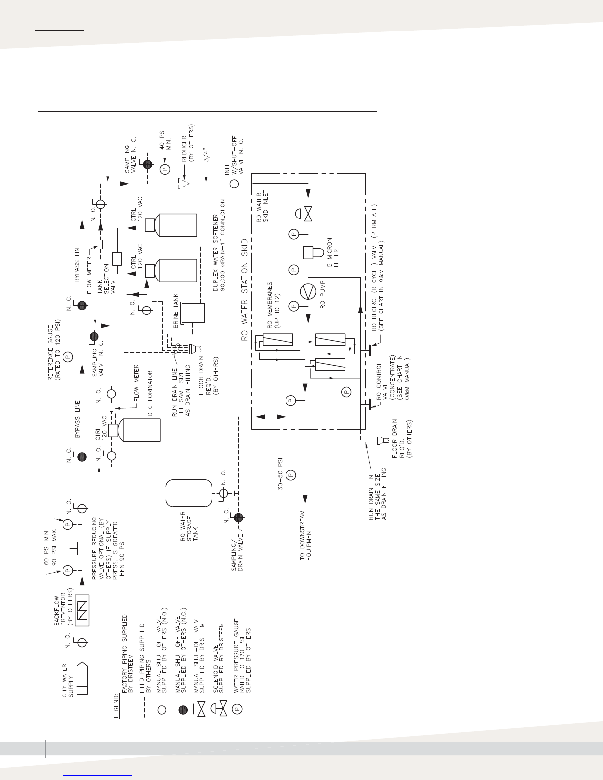
Piping and instrumentation arrangement
FIGURE 14-1: FLOW SCHEMATIC WITH A TANK DECHLORINATOR
to 2
u
to 2
u
to 2”
u
DRISTEEM WATER TREATMENT SYSTEMS INSTALLATION, OPERATION, AND MAINTENANCE MANUAL
14
OM-7828
Page 15

Piping and instrumentation arrangement
FIGURE 15-1: FLOW SCHEMATIC WITH A CARTRIDGE DECHLORINATOR
INSTALLATION
DRISTEEM WATER TREATMENT SYSTEMS INSTALLATION, OPERATION, AND MAINTENANCE MANUAL
OM-7829
15
Page 16

INSTALLATION
Interconnecting tubing requirements
Table 16-1:
Maximum length of interconnecting tubing between pump station and RO holding tank
RO station model
Volume
gpm L/m in. mm ft m
Tubing nominal
diameter
1/2" 0.375 10 >100 >30
Minimum tube I.D. Maximum developed length*
401 0.55 2.1
402 1.10 4.2
403 2.20 8.3
404 3.85 14.6
406 5.50 20.8
408 7.70 29.1
3/4" 0.625 16 >100 >30
1" 0.875 23 >100 >30
1/2" 0.375 10 64 >20
3/4" 0.625 16 >100 >30
1" 0.875 23 >100 >30
1/2" 0.375 10 18 5.5
3/4" 0.625 16 >100 >30
1" 0.875 23 >100 >30
1/2" 0.375 10 — —
3/4" 0.625 16 >100 >30
1" 0.875 23 >100 >30
1/2" 0.375 10 — —
3/4" 0.625 16 95 29
1" 0.875 23 >100 >30
1/2" 0.375 10 — —
3/4" 0.625 16 51 16
1" 0.875 23 >100 >30
412 12.1 45.8
* Calculations are based on pipe fi nish factor of 130 and low-pressure piping length of 1' (0.3 m).
** Installation must meet the minimum and maximum inlet pressures for all components, as stated in the specifi cation tables in the “Installation” section
of this manual.
mc_062012_1424
DRISTEEM WATER TREATMENT SYSTEMS INSTALLATION, OPERATION, AND MAINTENANCE MANUAL
16
1/2" 0.375 10 — —
3/4" 0.625 16 22 7
1" 0.875 23 89 27
Page 17

Components and tools needed
System confi guration may not include all components.
TYPICAL TOOLS/SUPPLIES NEEDED
• PTFE-tape
• Adjustable wrench for water fi ttings
• Screwdrivers for power connections and cabinet access
• Precision screwdrivers for signal connections
• Air compressor (for precharging RO tank)
TYPICAL FIELD-SUPPLIED COMPONENTS
• Gauges, fi ttings, and interconnecting piping as shown in Figure 14-1.
• Pipe supports/hangers (if needed)
• Reducing fi ttings for water connections (if needed)
• Drain line and clamp for fl ush valve
• Interconnecting piping and fi ttings
• Water softener salt (pulverized type recommended)
• Plastic tee for duplex-water-softener-to-brine-tank connection
• Funnel for pouring resin beads into duplex water softener tanks for 21" (533 mm) and larger
• Code approved electrical disconnect.
INSTALLATION
DRISTEEM WATER TREATMENT SYSTEMS INSTALLATION, OPERATION, AND MAINTENANCE MANUAL
17
Page 18

INSTALLATION
System piping
FOR SYSTEMS TO BE PIPED IN THE FIELD
WATER PRE-TREATMENT
Typical inlet pressure range to dechlorinator is 60 to 90 psi (415 to 620 kPa). Minimum inlet
dynamic (while running) pressure to dechlorinator is 60 psi (415 kPa).
DECHLORINATOR
For detailed instructions see the dechlorinator manual that shipped with your system.
Refer to Figure 14-1 for arrangement of piping and instrumentation.
1. Connect the water supply and bypass piping to the inlet of the dechlorinator.
2. Plumb drain outlet from the dechlorinator to nearby drain.
3. Connect outlet of dechlorinator to water softener inlet.
4. Plug in the power cord to a 120V, single-phase receptacle.
Wall mounted dechlorinator (Models 401 and 402 only):
1. Mount dechlorinator housing assembly near the water softener.
2. Insert carbon block filter and reattach blue housing.
3. Connect the water supply to the inlet of the dechlorinator.
4. Plumb dechlorinator outlet to water softener inlet.
5. For systems that have a tank style carbon filter with control valve: Be sure that the elastomeric
Drain Line Flow Control restrictor washer is installed correctly in the drain outlet plumbing
assembly prior to use. This item is required to prevent overflow and potential carry over of
carbon to the drain system.
For wall mounted systems that use extruded carbon black fi lter: Weekly chlorine level checks
are recommended. Once chlorine is determined to be passing through, change the carbon
fi lter. Typical life is 1-3 months depending on usage.
DUPLEX WATER SOFTENER
For detailed instructions see the water softener manual that shipped with your system.
Refer to Figure 14-1 for arrangement of piping and instrumentation.
1. Connect water supply and bypass piping to inlet to duplex water softener.
2. Connect brine tank to water softener control system using plastic hose supplied.
3. Add salt to brine tank. DriSteem recommends using pulverized salt because it dissolves easily.
4. Plumb drain outlet from water softener to nearby drain.
5. Connect water softener outlet to RO station inlet.
6. Plug in power cord to a 120V, single-phase receptacle.
DRISTEEM WATER TREATMENT SYSTEMS INSTALLATION, OPERATION, AND MAINTENANCE MANUAL
18
Page 19

System piping
INSTALLATION
RO STATION AND PRESSURIZED RO HOLDING TANK
Refer to Figure 14-1 for arrangement of piping and instrumentation.
Minimum inlet dynamic (while running) pressure is 40 psi (275 kPa).
1. Connect outlet of water softener to RO station inlet.
2. Plumb RO drain connection to drain.
3. Plumb RO water output to pressurized RO holding tank and downstream
equipment.
Be sure to install manual shut-off valve for pressurized RO holding tank as
shown in Figure 19-1 to prevent tank contamination while fl ushing the
RO system.
It is recommended to install an additional manual shut off valve with piping
for fl ushing and draining the system (see Figure 14-1 or 15-1.
4. Set recirc flow meter to desired level, but not above the maximum allowed
setting corresponding to specific model as shown in Table 10-1.
5. Precharge pressurized RO holding tank to 26 to 28 psi (180 to 195 kPa).
See “Pressurized RO Holding tank” on Page 39.
FIGURE 19-1: HOSE FROM RO WATER
OUTLET CONNECTED TO PRESSURIZED
RO HOLDING TANK
DRISTEEM WATER TREATMENT SYSTEMS INSTALLATION, OPERATION, AND MAINTENANCE MANUAL
19
Page 20

INSTALLATION
System piping
PLUMBING
Plumbing materials can signifi cantly contribute to the contamination of the
water. Care must be exercised over the choice of thread sealants. PTFE tape
is suitable for all threaded connections in this system. Pipe dope can leach
objectionable impurities into the water and must be avoided.
FEED WATER CONNECTION
Connect the raw water supply to the inlet of the solenoid valve, observing the
following:
• The line size shall be ¾ inches (19 mm) or larger to minimize pressure
loss.
• A manual valve should be installed on this line to shut off the water supply
if it will ever be needed. Be sure that this valve in no way restricts the
water fl ow when it is fully open.
• Water supply min pressure 40 psi (276 kPa). A pressure regulator may be
required if pressure is above 70 psi (483 kPa).
CAUTION
This unit produces high quality water
which could cause corrosion or
leaching of the plumbing following
the system. Use only plumbing
components of inert material that
are compatible with the application.
Copper plumbing cannot be used.
Important:
All plumbing is to be done in accordance with
state and local codes.
CAUTION
CONCENTRATE/REJECT CONNECTION
Connect a line to the single point drain outlet on the skid. The drain must have
a minimum capacity which meets or exceeds the combned output of all system
drains.
PERMEATE/PRODUCT WATER CONNECTION
Connect the product water line to the product connection point on the system.
Run this line to your storage tank or other downstream equipment, observing
the following:
• Run this line in such a manner as to minimize static head pressure in the
product line.
• The product line should have no restrictions to the product fl ow.
• Inspect to insure that no fl exible pumping lines have been kinked or
damaged during installation.
RO membranes will fail immediately
if the product water is allowed to fl ow
backward into the elements.
CAUTION
The highest point of the tubing should
not be higher than four feet above
the top of the RO modules, or the
elements may be damaged.
CAUTION
Do not fully close the manual valve
located directly after the RO pump.
This could cause cavitation and
premature pump failure.
CAUTION
DRISTEEM WATER TREATMENT SYSTEMS INSTALLATION, OPERATION, AND MAINTENANCE MANUAL
20
Damage to pump
Do not close the valve. Do not operate
the pump below minimum combined
fl ow rate (permeate + concentrate +
recirculating).
Models 401-402: 4 gpm (15.2 L/
min)
Models 403-412: 6 gpm (22.7 L/min)
Page 21

Connecting components
WIRING
• Ladder style wiring diagrams (included with unit, separate from this manual)
show power, control, and equipment-to-control-cabinet interconnection
requirements.
Note: If using a fi eld supplied fl oor water leak switch (terminals P15-3 and
P15-4) remove factory jumper from the control board.
• External connections diagrams (included with unit, separate from this
manual) show connection points to the microprocessor-based controller and
wire terminals for external safety and control devices.
All wiring must be in accordance with all governing codes and with wiring
diagrams.
ELECTRICAL INSTALLATION
Wiring and branch circuit protection is provided by the installer per NEC (or
IEC 60364 in Europe) requirements.
For power supply and machine ground con nec tions, size the wire using the
75 °C wiring table, per NEC (or IEC 60364 in Europe) requirements. Then use
copper conductors rated for a 105 °C en vi ron ment. The wiring from the control
cabinet to the equipment must be rated for 105 °C.
Verify electrical current characteristics (voltage, phase and amp draw) and
capacity requirements against those listed on the name plate.
SERVICE DISCONNECT
A service disconnect must be installed per NEC requirements and governing
codes.
PREVENTING ELECTRICAL NOISE
INSTALLATION
WARNING
Electric shock hazard
Only qualifi ed electrical personnel
should perform fi eld wiring installation
procedures. Improper wiring or contact
with energized circuits can cause
property damage, severe personal
injury, or death as a result of electric
shock and/or fi re.
Do not open control cabinet, pump
motor, or subpanel access panels until
electrical power is disconnected.
CAUTION
Damage from debris
When drilling penetrations in the
control cabinet, protect all internal
components from debris, and vacuum
out the control cabinet when fi nished.
Failure to comply with this directive
can damage sensitive electronic
com po nents, cause erratic operation
or failure, and void your DriSteem
warranty.
Electrical noise can produce undesirable effects on electronic control circuits,
thereby affecting controllability. Electrical noise is generated by electrical
equipment such as inductive loads, electric motors, solenoid coils, welding
machinery, or fl uorescent light circuits. The electrical noise or interference
generated from these sources (and the effect on controllers) is diffi cult to defi ne,
but the most common symptoms are erratic control or intermittent operational
problems.
Most electrical noise problems can be prevented by using proper wiring
practices and techniques to prevent coupling or inducing of electrical
interference into control circuits. The following wiring practices should minimize
interaction of noise and controls:
• Connect unit and control cabinet to a code approved earth ground.
• Separate the line voltage wiring from low voltage control circuit wiring
when routing electrical wiring inside the control cabinet.
DRISTEEM WATER TREATMENT SYSTEMS INSTALLATION, OPERATION, AND MAINTENANCE MANUAL
Important:
Failure to follow these wiring procedures can
result in erratic operation or failure.
This product has been tested at the factory for
proper operation. Product failures resulting from
faulty handling, incorrect wiring, or shorting of
wires together on external components are not
covered under your DriSteem warranty. Review
information and di a grams before proceeding.
21
Page 22

INSTALLATION
Connecting components
GROUNDING REQUIREMENTS
The approved earth ground must be made with solid metal-to-metal connections
and must be a good con duc tor of radio frequency interference (RFI) to earth
(multistranded conductors).
Ground wire should be the same AWG (mm2) size as the power wiring or
sized per NEC requirements (in Europe, IEC 60364 requirements).
When the control cabinet is mounted remotely from the unit, a ground wire
is necessary from the machine ground lug on the unit to the machine ground
lug in the control cabinet. The bonding machine ground wire should be the
same AWG (mm2) as the largest heater wire or sized per NEC or IEC 60364
requirements.
CAUTION
On three-phase units ensure proper
supply line voltage wiring. Incorrect
wiring will cause the RO pump to run
backwards and void your DriSteem
warranty.
DRISTEEM WATER TREATMENT SYSTEMS INSTALLATION, OPERATION, AND MAINTENANCE MANUAL
22
Page 23

OPERATION
Start-up checklist
If an item in the Start-up checklist below does not apply to your system, skip to the next item and continue the process.
☐ Read this manual and all other information that was provided with your system.
☐ Verify that all fi eld wiring is done according to the instructions in this manual and in the unit wiring diagram.
☐ Confi rm that proper grounding and an approved earth ground are provided.
☐ Confi rm that the keypad/display is mounted with its modular cable routed away from high-voltage circuits and
connected to the Display connector on the Vapor-logic board.
☐ Install cartridge fi lter and check for leaks. (See “System Piping” on Page 20.)
☐ Precharge pressurized RO storage tank to 28 psi (195 kPa).
Note: This precharge pressure is for pressurized RO storage tank cut-in and cut-out switch points at 30 and 50 psi
(210 and 345 kPa) respectively.
☐ Turn on the water supply, and confi rm there are no leaks.
☐ Turn on power to the unit, and confi rm the Main menu is displayed on the keypad/display. The display may take
several seconds to appear as the controller powers up.
☐ Confi rm in the Main Menu that the mode is “Auto” and that status is “Idle.”
☐ When “Idle” appears in main menu, confi rm that the inlet pressure is at least 40 psi (276 kPa) on the display.
☐ With suffi cient water available, the system in Auto mode, and the storage tank pressure less than 30 psi (210 kPa),
verify that the pump is activated.
☐ Set perm fl ow and recirc fl ow meter to desired setting.
☐ Systems with tank-style carbon fi lter with control valve: Ensure that elastomeric Drain Line Flow Control restrictor
washer is installed correctly in drain outlet plumbing assembly. This is required to prevent overfl ow and potential
carry-over of carbon to the drain system.
See “Dechlorinator” on Page 18 of this manual.
☐ If you experience diffi culties, have the keypad/display information available along with the serial number and unit
Model, and call DriSteem Technical Support at 800-328-4447.
Note: Instructions on how to properly care for the freeze protect chemical that is shipped with the system is available
on the MSDS sheet at www.dristeem.com.
☐ Inspect to insure that no fl exible plumbing lines have been kinked or damaged during installation.
WARNING
Tipping hazard
Before installing the 400 series
reverse-osmosis system, use
supplied leg brackets or lag points
to permanently fi x the system to
the fl oor and/or adjacent building
structure. Failure to install according
to instructions can result in serious
injury or death. See page 13 for
instructions.
DRISTEEM WATER TREATMENT SYSTEMS INSTALLATION, OPERATION, AND MAINTENANCE MANUAL
23
Page 24

OPERATION
Start-up
START-UP PROCEDURE
Check component installation per the layout shown in Figure 14-1
(depending on your model). After all components are installed and connected
properly:
1. Perform all applicable “Start-up checklist” items on Page 23.
2. Read and follow instructions in the “Operation” section of Vapor-logic
Installation and Operation Manual.
Note: During start-up, do not leave the system unattended.
TEST OPERATION
Using the keypad/display or web interface, place the zone controllers (if
DriSteem controlled) and pump station in Auto mode. For each zone, perform
the following procedure:
If the system has a full RO holding tank, create a call for water by draining
water from the tank until the pressure falls below 30 psi (210 kPa).
3. Monitor system performance, and watch for leaks.
4. If a leak is found:
a. Remove demand signal, and put the system in Standby mode.
b. Tighten any loose connections.
c. Return system to Auto mode.
d. If a leak persists, replace tubing or fi tting that is leaking.
Important
If the system is not in operation within six
months of shipment, it is strongly recommended
to use an organic cleaning cartridge prior
to performing the start-up checklist to ensure
proper operation. See page 36 for
information and part number.
CAUTION
If the pump chatters loudly, it is
starving for water (cavitating). Turn the
unit OFF immediately to prevent pump
damage. Correct the low pressure
condition before proceeding.
5. Leave system in Auto mode. It will automatically refill the RO holding tank
when pressure falls below 30 psi (210 kPa).
INITIAL SYSTEM START-UP
1. Close the manual valves to both the RO holding tank and all downstream
equipment. Open the manual valve leading to the drain.
2. Open the feed water supply valve.
3. Open the system pressure (pump throttle) control valve fully
counterclockwise (if applicable). Open the concentrate control valve fully
counterclockwise. Close the recycle valve.
4. Put the system into 'Auto' mode. Note inlet water pressure must be at least
40 psi (276 kPa).
5. If incoming pressure is too high, an inlet pressure regulator (not included)
may be installed. This should be set at 40 psi (276 kPa).
6. Some fittings may have loosened during shipment. Check for leaks at all
tube fittings and threaded joints.
7. Allow the unit to run for at least 30 minutes to flush the preservative
solution from the system.
DRISTEEM WATER TREATMENT SYSTEMS INSTALLATION, OPERATION, AND MAINTENANCE MANUAL
24
Page 25

Start-up
OPERATION
8. Once the preservative solution has been flushed from the system, shut
down the system by putting the system into 'Standby' mode on the Vaporlogic keypad and close the manual valve going to the drain. Open the
manual valves to both the RO storage tank and downstream equipment.
9. Put the system back into 'Auto' mode.
10. Adjust the throttle valve to get the specified permeate flow (if applicable).
11. Adjust the concentrate valve and recycle valve until the specified permeate
flow and recycle flow are obtained. It may be necessary to readjust the
throttle valve. See Table 26-1.
12. Test the operation of the pressure switch by slowly closing the inlet water
supply valve. The unit should shut off after a short 5 second time delay.
13. Once all the desired flows are set, allow the system to run for
approximately 30 minutes. Then record the performance information using
the system operation data log on page 42. The values recorded at
startup will be important for determining system performance at a later
date.
OPERATING DO'S AND DONT'S
DO
1. Change the cartridge filters regularly
2. Monitor the system and keep a log daily
CAUTION
Do not operate the system with the
control valve closed.
Important:
By setting the feed pressure as low as possible
to meet the application requirement, the
service life of the pump and RO elements
will be optimized. The system should be run
continuously when possible, rather than go
through frequent start/stop cycles.
CAUTION
Damage to pump
Do not close the valve. Do not operate
the pump below minimum combined
fl ow rate (permeate + concentrate +
recirculating).
Models 401-402: 4 gpm (15.2 L/
min)
Models 403-412: 6 gpm (22.7 L/min)
3. Run the system, as much as possible, on a continuous basis.
4. Adjust the system recovery to the recommended value
DON’T
1. Permit chlorine in the feed water.
2. Shut down the system for extended periods. If system will be down for
more than one month, treat the system with a membrane preservative. See
page 37 for instructions.
3. Close the throttle valve completely.
4. Operate the system with insufficient feed flow.
DRISTEEM WATER TREATMENT SYSTEMS INSTALLATION, OPERATION, AND MAINTENANCE MANUAL
25
Page 26

OPERATION
System operation
SHUTDOWN
1. Put the system in 'Standby' mode or remove power. Close the isolation
valve if it is installed on the feed line.
2. If the unit is to be shut down for more than one week, a membrane
preservative should be used. To accomplish this, perform 30 second
flush using cartridge filter insert (see page 24 and 36 for more
information). After 30 seconds, press the power button OFF, and close the
concentrate valve. This will hold the preservative in the pressure vessel.
3. When the system is restarted after an extended shutdown, follow initial
system start-up procedures.
FIGURE 26-1: CONTROL VALVES
CAUTION
To prevent concentrate from
precipitating and causing irreversible
fouling of the RO membrane, do not
operate the system with the control
valve completely closed.
CAUTION
Do not exceed recommended
maximum recovery.
Table 26-1:
Recommended concentrate and permeate flow
Permeate fl ow Concentrate fl ow Recirc (recycle)*
RO station model
401 1.0 3.8 0.9 - 4.3 3.4 - 16.3 0 - 3.4 0 - 12.9
402 1.7 6.4 1.6 - 2.6 6.1 - 9.8 0.8 - 1.8 3.0 - 6.8
403 2.9 11.0 2.3 - 3.5 8.7 - 13.2 1.0 - 2.2 3.8 - 8.3
404 3.6 13.6 1.5 - 3.0 5.7 - 11.4 1.0 - 2.5 3.8 - 9.5
406 5.5 20.8 2.0 - 4.0 7.6 - 15.1 1.5 - 3.5 5.7 - 13.2
408 7.2 27.3 3.5 - 4.5 13.2 - 17.2 2.0 - 3.0 7.6 - 11.4
412 11.0 41.6 3.5 - 4.5 13.2 - 17.2 2.0 - 3.0 7.6 - 11.4
*Higher recirculation increases water effi ciency.
gpm L/m gpm L/m gpm L/m
DRISTEEM WATER TREATMENT SYSTEMS INSTALLATION, OPERATION, AND MAINTENANCE MANUAL
26
Page 27

Vapor-logic keypad/display
FIGURE 27-1: USING THE VAPOR-LOGIC KEYPAD/DISPLAY
Typical Home screen
Tank pressure/status
Change Mode from the Home
screen by pressing the Up or
Down arrow keys until Mode
is highlighted, press Enter,
press Up or Down arrow keys
to change, press Enter to
confi rm
OPERATION
Total dissolved solids (TDS)
Status
Press Main softkey for
Main menu; other softkey
functions vary by screen
Press Up or Down
arrow to move through
menus and screens
Alarm
label flashes
when there is a
system alarm
Message
label fl ashes
when there is a
system message
Press
Enter
to select or
confi rm
DRISTEEM WATER TREATMENT SYSTEMS INSTALLATION, OPERATION, AND MAINTENANCE MANUAL
27
Page 28

OPERATION
Keypad/display Home screens,Test outputs, Test run
Vapor-logic returns to the Home screen on the keypad/display
after a user-defi ned period of idleness. The Home screen displays
the items most frequently viewed.
CHANGING MODE
Mode can be changed from the Home screen. Press the Up or
Down arrow key until the Mode is highlighted, press Enter, press
Up or Down arrow key to change value, press Enter to confi rm.
All other parameters shown on the Home screen are for viewing
only and cannot be changed. Go to the Setup menu to change
these items.
CONTROLLER DISPLAY ACTIVITY DEFINITIONS (FIGURE 28-1)
RO fl ush: System is performing an RO fl ush.
Idle: No demand, or an active alarm is preventing operation.
Filling: System is supplying high-pressure water to meet demand.
Full: Storage tank is full, system not running.
TEST OUTPUTS
When completing an installation or repair, cycle all outputs, to
verify operation. Go to the test outputs section of the Diagnostics
menu and scroll through each connected output to verify
operation. During testing, the unit mode changes to Standby and
the tank status changes to Test.
FIGURE 28-1: RO STATION KEYPAD/
DISPLAY HOME SCREEN
TEST RUN
Vapor-logic has a test run capability to confi rm system
functionality. This capability allows a technician to simulate a
demand when there isn’t one (such as when performing routine
maintenance). To confi rm functionality, go to the test run section of
the Diagnostics menu. Set system demand percent and set test run
time duration. During testing, the unit mode changes to Standby
and the tank status changes to Test.
DRISTEEM WATER TREATMENT SYSTEMS INSTALLATION, OPERATION, AND MAINTENANCE MANUAL
28
Page 29

Status screen
Table 29-1:
Status screen
Note: Your system might not have all of the items listed in this table.
OPERATION
Menu
item
Run mode Standby -- -- --
TDS -- 0 9999 ppm
TDS set point 50 0 100 ppm
Water temperature
Safety interlock Closed Open Closed --
Inlet pressure switch -- No water Water --
Storage pressure -- 0 100 psi Storage tank pressure.
Pump hours -- 0 100,000 Hours
Default
value
Minimum
value
-- -50 250 °F Sensor range
-- -46 121 °C Sensor range
Maximum
value
Units Notes
Operating mode of unit. Choose from Auto, Standby, or Drain.
• In Auto mode, the unit operates normally. All unit components are monitored
and controlled. If there is a call for cooling/humidifi cation, the system reacts.
• In Standby mode, the unit is offl ine. All control inputs appear but are not
acted upon; however, if the water temperature falls below the freeze protect
set point, the drain valve opens.
• In Drain mode, the RO Flush valve opens, the RO tank drains, and the RO
system begins making RO water. All unit operation is suspended, and the RO
Flush valve remains open until the model specifi c RO fl ush time is met the unit
is taken out of RO fl ush mode, or the RO tank is drained.
• See the Diagnostics section for information about Test outputs and Test run
modes.
Table 29-2:
Setup screen
Note: Your system might not have all of the items listed in this table.
Menu
item
Membrane fl ush 300 0 300 seconds
System fl ush 72 1 336 hours
Default
value
Minimum
value
Maximum
value
Units Notes
Table 29-3:
TDS setting
Note: Your system might not have all of the items listed in this table.
Menu
item
High TDS causes Alarm Message Alarm --
TDS setpoint 50 25 100 --
Default
value
Minimum
value
Maximum
value
Units Notes
DRISTEEM WATER TREATMENT SYSTEMS INSTALLATION, OPERATION, AND MAINTENANCE MANUAL
29
Page 30

OPERATION
Diagonstics and Alarms
Table 30-1:
Diagnostics menu
Note: Your system might not have all of the items listed in this table.
Message Description Auto-clear?
Pretreat lockout Softener or other pretreatment is preventing the RO station from operation. Yes
No master enable Master enable for the system is open. Yes
Excessive TDS
Service unit Regularly scheduled unit servicing is due. No
I-lock open Interlock safety switch is open. Yes
Notes:
• The Messages Log displays message name, date and time of occurrence, plus “Active,” “Cleared” or “Auto-cleared.”
• Active messages display fi rst in the Messages Log, followed by cleared messages (auto-cleared and/or manually-cleared) listed in order of
occurrence.
• The Messages Log displays a maximum of 10 messages. Cleared messages leave the log fi rst.
• If a message event occurs and is not manually or auto cleared during unit operation, the message will stay there until there is demand and the
unit is running.
TDS measurement during RO production exceeds the TDS set point.
The system will continue to operate but the membranes may need to be replaced.
Yes
Table 30-2:
Alarm menu
Alarm level Description Auto-clear?
Temp sensor fault Water temperature/TDS sensor reading is out of range. Yes
Low inlet pressure Water pressure at RO inlet is less than 10 psi. Yes
High storage
pressure
Floor sensor active Optional fl ooded fl oor pan circuit is active. No
Storage pressure
sensor
Excessive TDS
Notes:
• See the "troubleshooting" section in the Vapor-logic Installation and Operation Manual for alarm possible causes and recommended actions.
• The Alarms Log displays alarm name, date, and time of occurrence, plus "Active," "Cleared," or "Auto-cleared."
• Active alarms display fi rst in the Alarms Log, followed by cleared alarms (auto-cleared and/or manually-cleared) listed in order of occurrence.
• The Alarms Log displays maximum 30 alarms. Cleared alarms leave the log fi rst.
• If an alarm event occurs and is not manually cleared or auto-cleared during unit operation, the alarm will remain until there is demand and the
unit is running.
Tank storage pressure has exceeded 60 psi. Yes
Pressure sensor reading is out of range. Yes
TDS measurement during RO production exceeds the TDS set point.
The system will continue to operate but the membranes may need to be replaced.
No
DRISTEEM WATER TREATMENT SYSTEMS INSTALLATION, OPERATION, AND MAINTENANCE MANUAL
30
Page 31

OPERATION
Modbus, BACnet, LonTalk interoperability
Table 31-1:
Interoperability vaiable and object names
Variable name and
BACnet object name
Read-only analog variables
Storage_pressure RO IR-1 AI-1 nvoStoragePress Storage pressure psi bar 0 100
Pump_1_hour RO IR-2 AI-2 nvoPumpHours Hours of operation hours hours 0 100000
Water_temp RO IR-3 AI-3 nvoWaterTemp
TDS RO IR-4 AI-4 nvoTDS TDS — — 0 9999
Set Variables
Run_mode
TDS_setpoint RW HR-2 AV-1 nviTDS_SP TDS set point — — 0 100
Read-only digital I/O
Safety_interlock RO DI-1 BI-01 nvol-LockSW
Pretreat_lockout_sw RO DI-2 BI-02 nvoPreTreatSW
Floor_water_sw RO DI-3 BI-03 nvoFloorSW
Inlet_pressure_sw RO DI-4 BI-04 nvoInletPressSW
Master_enable_sw RO DI-5 BI-05 nvoMasterEnabSW
Supply_valve RO DI-6 BO-01 nvoSupplyValve
Drain_valve RO DI-7 BO-02 nvoDrainValve
RO_pump RO DI-8 BO-03 nvoROpump 0=Off; 1=On ————
Notes:
1. Modbus Input Registers (IR1-IR4) 16 bit read only
Modbus Holding Registers (HR1-HR2) 16 bit read/write
Modbus Discrete Input Registers (DI1-DI8) single bit read only
Modbus Coil Registers (DV1-DV8) single bit read/write
2. nvi LonTalk SNVTs are write-only; nvo are read-only
Read Only
(RO) or
Read Write
(RW)
Write HR-1 MSV-01 nviRunMode
Read HR-1 MSV-01 nvoRunMode
Modbus
register
number*
BACnet
Object
Type and
Instance
LonTalk variable
names**
Description Units Range
I-P units SI units I-P units SI units
Temperature of RO
water
Mode of the unit
or system. The
defi ned options
are:
1=Auto;
2=Local standby;
3=System standby;
4=Manual drain;
5=Test outputs;
6=Test run
Mode of the unit
or system. The
defi ned options
are:
1=Auto;
2=Local standby;
3=System standby;
4=Manual drain;
5=Test outputs;
6=Test run
0=Open;
1=Closed
0=Open;
1=Closed
0=Water;
1=No Water
0=No Water;
1=Water
0=Open;
1=Closed
0=Open;
1=Closed
0=Open;
1=Closed
F C -50 to 250 -46 to 121
— — 1 to 4 1 to 4
1 to 6 1 to 6
————
————
————
————
————
————
————
DRISTEEM WATER TREATMENT SYSTEMS INSTALLATION, OPERATION, AND MAINTENANCE MANUAL
31
Page 32

OPERATION
Modbus, BACnet, LonTalk interoperability
Table 32-1:
Interoperability vaiable and object names
Variable name and
BACnet object name
Faults and Alarms
ProgOutput1_status RW DV--01 BV-01 nvoDryConStat1 NO or NC output — — — —
ProgOutput2_status RW DV-02 BV-02 nvoDryConStat2 No or NC output — — — —
Active_manually_
cleared_alarm_exists
Clear_all_faults RW DV-04 BV-04 nviClrAllFault
Alarm_temp_sensor_
failed
Alarm_low_inlet_
pressure
Alarm_excessive_
storage_pressure
Alarm_fl oor_water_
sensor_activated
Alarm_pressure_sensor_
out_of_range
Alarm_excessive_TDS_
during_fi ll
Message_pretreat_
lockout_active
Message_excessive_
TDS_during_fi ll
Message_service_unit RW DV-13 BV-13 nvoMsgSrviceUnt
Message_interlock_open RW DV-14 BV-14 nvoMsgllockOpen
Message_master_
enable_open
Notes:
1. Modbus Input Registers (IR1-IR11) 16 bit read only
Modbus Holding Registers (HR1-HR10) 16 bit read/write
Modbus Discrete Input Registers (DI1-DI9) single bit read only
Modbus Coil Registers (DV1-DV15) single bit read/write
2. nvi LonTalk SNVTs are write-only; nvo are read-only
Read Only
(RO) or
Read Write
(RW)
RW DV-03 BV-03 nvoAlarmManCl
RW DV-05 BV-05 nvoAlmTempSense
RW DV-06 BV-06 nvoAlmInPress
RW DV-07 BV-07 nvoAlmOutPress
RW DV-08 BV-08 nvoAlmFloorWet
RW DV-09 BV-09 nvoAlmPrSensOOR
RW DV-10 BV-10 nvoAlmExcessTDS
RW DV-11 BV-11 nvoMsgPretreatL
RW DV-12 BV-12 nvoMsgExcessTDS
RW DV-15 BV-15 nvoMsgNoMastEnb
Modbus
register
number*
BACnet
Object
Type and
Instance
LonTalk variable
names**
Description Units Range
I-P units SI units I-P units SI units
Flags all manually
cleared alarms
When set will clear
all active faults
See Table 30-1:
Alarm menu
See Table 30-1:
Alarm menu
See Table 30-1:
Alarm menu
See Table 30-1:
Alarm menu
See Table 30-1:
Alarm menu
See Table 30-1:
Alarm menu
See Table 30-2:
Diagnostics menu
See Table 30-2:
Diagnostics menu—
See Table 30-2:
Diagnostics menu—
See Table 30-2:
Diagnostics menu—
— See Table
30-2: Diagnostics
menu
——— —
——— —
——— —
——— —
——— —
——— —
——— —
——— —
——— —
——— —
——— —
——— —
——— —
DRISTEEM WATER TREATMENT SYSTEMS INSTALLATION, OPERATION, AND MAINTENANCE MANUAL
32
Page 33

Maintenance information
MAINTENANCE
MAINTENANCE TIPS
Maintain proper operating conditions:
• Do not exceed 60-90 psi (414-620 kPa)on the system inlet pressure gauge.
• Do not over use recycle fl ow. This can cause premature scaling of the
membrane. A proper concentrate fl ow is required for a long membrane life.
See page 10 for maximum recycle fl ow.
• To ensure no chlorine reaches the RO membranes, test the water from your
dechlorinator periodically for chlorine break through.
WHEN TO CHANGE SEDIMENT FILTERS
Sediment fi lters should be changed regularly to maintain proper pressure and
fl ow.
Change the fi lters when the difference between fi lter pressure gauge increases
by 10 psi over the initial pressure difference. For example, if initial readings
are 60 psi in and 58 psi out, the difference is 2 psi. Therefore, when that
difference reaches 12 psi, it is time to replace the sediment and carbon
cartridges.
WHEN TO CLEAN MEMBRANES
In normal operation, the membrane in reverse osmosis elements can become
fouled by mineral scale, biological matter, and grime. These deposits build
up during operation until it causes loss in water output or loss of salt rejection,
or both. Elements should be cleaned or replaced whenever the water output
rate drops by 10 percent from its initial fl ow rate (the fl ow rate established
during the fi rst 24 to 48 hours of operation) or when TDS in the product water
(permeate) rises above 50. Use the factory mounted TDS sensor located on the
right side of the system.
FIGURE 33-1: SEDIMENT FILTER
DriSteem replacement part
• 2½" x 20" - Model 401-404
(part number: 550026-003)
• 4" x 20" - Model 406-412
(part number: 550026-004)
It should be noted that the water output rate will drop if feed water temperature
decreases (about 1.5% per °F). This is normal and does not indicate membrane
fouling. A malfunction in the pretreatment, pressure control or pump can cause
a drop in feed water delivery pressure, feed water fl ow, product water output,
or an increase in salt passage. If such adjustments are needed, the element
may not require cleaning.
MEMBRANE CLEANING AND PRESERVATIVE CARTRIDGES
• Clean and preserve membranes without removing them from your system
• Reduce downtime
• Maintain your system performance at a higher level
• Prolong membrane life by regular use of cleaning cartridge
DRISTEEM WATER TREATMENT SYSTEMS INSTALLATION, OPERATION, AND MAINTENANCE MANUAL
33
Page 34

MAINTENANCE
Maintenance continued
SEDIMENT PRE-FILTER CARTRIDGE
WHEN TO CHANGE SEDIMENT PREFILTER CARTRIDGE
Sediment fi lters should be changed regularly to maintain proper pump pressure
and fl ow. If the pressure drop across the cartridge fi lter (as indicated by the
differential between the fi lter inlet and fi lter outlet pressure gauges) increases
by 10 psi, the sediment fi lters should be changed.
CHANGING CARTRIDGE FILTERS
1. Put the system into 'Standby' mode and shut down the RO system.
2. Close inlet supply valve.
3. Un-assemble the filter housing (twist the sump counter-clockwise).
4. Remove and inspect the cartridge. Replace as needed.
5. Before replacing housing, insure that O ring seal is lubed and placed in
groove of housing. Inspect seal and replace as needed.
6. Assemble housing (turn the sump clockwise into the cap until tight).
DRISTEEM WATER TREATMENT SYSTEMS INSTALLATION, OPERATION, AND MAINTENANCE MANUAL
34
Page 35

Maintenance continued
MAINTENANCE
MEMBRANE CLEANING IN THE RO SYSTEM
Membrane cleaning cartridges:
• Clean membranes without having to remove them from the RO system
• Reduce downtime
• Maintain the system performance at a higher level
• Prolong membrane life by regular use of cleaning cartridges
HOW DOES IT WORK?
NOTE: Clean monthly to obtain optimum results.
1. Exchange the system's sediment filter with a cleaning cartridge.
2. Follow the instructions.
3. Restart the system.
4. Repeat the process if required.
SCALE CLEANING CARTRIDGE
The scale cleaning cartridge is for removal of mineral scale and build-up.
CLEANING PROCEDURE
1. Put the system into 'Standby' mode and shutdown the RO system.
2. Disconnect permeate line and divert to drain before any cleaning
cartridge is installed.
3. Remove the sediment filter from the pre-filter housing.
FIGURE 35-1: 20 INCH BIG BLUE SCALE
CLEANING CARTRIDGE
DriSteem replacement part
• 2½" x 20" - Model 401-404
(part number: 550045-001)
• 4" x 20" - Model 406-412
(part number: 550045-201)
CAUTION
Handle all chemicals with care. Wear
protective clothing and eye protection.
4. Replace the sediment filter with the cleaning cartridge and assemble into
the filter housing.
5. Turn the system ON and put into 'Auto' mode. After 30-40 seconds, shut
down the system.
OPTIONAL: Instead of time, use one of the following criteria:
a. Run the system until the pH of the concentrate is almost the same as the
cleaning solution (pH=3)
b. Permeate rate for the system drops to a very low value.
6. Let the membrane(s) soak in the cleaning solution overnight.
7. Remove the empty cleaning cartridge and replace it with the original filter.
8. Restart the system. Direct the permeate to drain for five minutes.
9. Go back to normal operations.
CAUTION
The system must be fl ushed thoroughly
between acid and alkaline cleaning.
DRISTEEM WATER TREATMENT SYSTEMS INSTALLATION, OPERATION, AND MAINTENANCE MANUAL
35
Page 36

MAINTENANCE
Maintenance continued
ORGANIC CLEANING CARTRIDGE
The organic cleaning cartridge is for removal of organics/fouling.
CLEANING PROCEDURE
1. Put the system into 'Standby' mode and shutdown the RO system.
2. Disconnect permeate line and divert permeate to drain during cleaning.
3. Remove the sediment filter from the filter housing.
4. Replace the sediment filter with the cleaning cartridge and assemble into
the filter housing.
5. Turn the system ON. After 30-40 seconds, shut down the RO system.
OPTIONAL: Instead of time, use one of the following criteria:
a. Run the system until the pH of the concentrate is almost the same as the
cleaning solution (pH=10-12)
b. Permeate rate for the system drops to a very low value.
6. Let the membrane(s) soak in the cleaning solution overnight.
7. Remove the empty cleaning cartridge and replace it with the original filter.
8. Restart the system. Direct the permeate to drain for five minutes.
9. Go back to normal operations.
FIGURE 36-1: 20 INCH BIG BLUE
ORGANIC CLEANING CARTRIDGE
DriSteem replacement part
• 2½" x 20" - Model 401-404
(part number: 550045-101)
• 4" x 20" - Model 406-412
(part number: 550045-301)
CAUTION
Handle all chemicals with care. Wear
protective clothing and eye protection.
CAUTION
The system must be fl ushed thoroughly
between acid and alkaline cleanings.
DRISTEEM WATER TREATMENT SYSTEMS INSTALLATION, OPERATION, AND MAINTENANCE MANUAL
36
Page 37

Storage
MAINTENANCE
To prevent bacterial growth and help maintain fl ux, it is recommended that
elements be immersed in a preservative solution if the system will be OFF for
more than one week.
MEMBRANE PRESERVATIVE CARTRIDGE
PRESERVING PROCEDURE
1. Put the system into 'Standby' mode and shutdown the RO system.
2. Disconnect the permeate line and direct permeate to drain during
cleaning/preserving.
3. Remove the sediment filter from the pre-filter housing.
4. Replace the sediment filter with the preservative cartridge and assemble
into the filter housing.
5. Turn the system ON. After 30-40 seconds, shut down the system.
6. Drain the system of the permeate solution as much as possible by opening
a valve/fitting at a low point in the system.
7. Put the system into 'Standby' mode and shutdown the RO system.
8. Close OFF the inlet and outlet to the system.
FLUSHING OUT PRESERVATIVE/RESTART PROCEDURE
FIGURE 37-1: 20 INCH BIG BLUE
PRESERVATIVE CARTRIDGE
DriSteem replacement part
• 2½" x 20" - Model 401-404
(part number: 550045-801)
• 4" x 20" - Model 406-412
(part number: 550045-901)
CAUTION
9. Open valves and put the system back in the position it was before
preserving.
10. Remove the empty preservative cartridge and replace it with a new
sediment filter.
11. Restart the system. Direct permeate to drain for 15-30 minutes.
12. Go back to normal operation.
Handle all chemicals with care. Wear
protective clothing and eye protection.
CAUTION
The system must be fl ushed thoroughly
between acid and alkaline cleanings.
DRISTEEM WATER TREATMENT SYSTEMS INSTALLATION, OPERATION, AND MAINTENANCE MANUAL
37
Page 38

MAINTENANCE
Membrane replacement
TOOLS
• Rubber mallet
• Flat blade screwdriver
• Open end wrench, ⅞ inch
• Food grade RT-111 silicone
• Safety glasses
MEMBRANE REPLACEMENT
1. Remove clamps from vessel using 9/16” socket or wrench. Use two screw
drivers on each side to push end caps out of vessel slowly.
2. Push the membrane out through the vessel from the feed end towards the
concentrate end.
3. If there is not enough room to remove the membrane from the vessel
through the concentrate end it can be removed from the feed end.
4. Install the new membrane from the feed end. Ensure that the brine seal
is oriented towards the feed end. Check that the end adapters and all
O-rings are in good condition and in position.
5. Replace end plug(s) using glycerin lubricant as required on O-rings.
6. It is highly recommended to have a spare set of O-rings and brine seal
while replacing the membranes.
7. As the membranes may have preservative or be contaminated, wash your
hands thoroughly after replacing membranes.
Note: Keep all plumbing routed the same as shipped from DriSteem. Any
different orientation will destroy the RO membranes.
FIGURE 38-1: DRISTEEM REVERSE
OSMOSIS MEMBRANES
DriSteem replacement
part number
550035-040.
Clamp
WARNING
Team lift required
Membrane banks are heavy. Do not
try to lift without assistance. Wear
steel-toed shoes and have adequate
room for maneuvering when servicing.
Never lean membrane banks vertically
when removed from system. Failure to
do so may damage the system or result
in injury.
DRISTEEM WATER TREATMENT SYSTEMS INSTALLATION, OPERATION, AND MAINTENANCE MANUAL
38
Page 39

Components
GAUGES AND VALVES
Verify proper operation by visual inspection during operation.
DECHLORINATOR
1. Visually inspect components for leaks or breakage.
2. Monthly, have a water sample taken after dechlorinator to check for
chlorine. If 2 ppm or greater, replace carbon media.
WATER SOFTENER
1. Check brine tank salt level at least weekly. Maintain salt level above the
half-full mark at all times.
Note: DriSteem recommends using pulverized salt because it dissolves
easily.
2. Visually inspect all components for leaks or breakage.
3. Annually, have a water sample taken downstream from water softener to
check for hardness. If water hardness is 15 ppm or greater, make sure
there is salt in brine tank. If there is salt, and water hardness if 15 ppm or
greater, contact DriSteem for water softener resin replacement.
MAINTENANCE
4. See water softener service manual for recommended service.
PRESSURIZED RO HOLDING TANK
1. Precharge pressurized RO holding tank with air to 26 to 28 psi (180 to
195 kPa) using Schrader valve on top of the tank.
2. Set pressurized RO storage tank to cut in at 30 psi (210 kPa) and cut out
at 50 psi (345 kPa). See instructions that shipped with Pressurized RO
holding tank and RO station interface kit.
3. Check cut-in and cut-out pressures as follows:
Drain pressurized RO holding tank until RO generation cycle begins. Verify
that starting and stopping pressures are approximately 30 psi and 50 psi
(210 and 345 kPa) respectively.
DRISTEEM WATER TREATMENT SYSTEMS INSTALLATION, OPERATION, AND MAINTENANCE MANUAL
39
Page 40

MAINTENANCE
Troubleshooting
The following troubleshooting instructions are specifi c to the DriSteem Reverse-Osmosis System. For additional
information, including messages and alarms, see the Vapor-logic section of this manual and the main Vapor-logic
controller installation, operation, and maintenance manual.
Table 40-1:
Troubleshooting
Issue Action
The system does not start manually or
automatically.
The system is operating but provides
only low pressure or no pressure.
Check supply voltage.
Check circuit breakers.
Check interlock switch.
Verify that the fi eld supplied manual inlet valve is open.
Verify that the water pressure is at least 40 psi (276 kPa).
Verify that the sediment fi lter is clean.
Check for alarms.
Check the control and power fuses located inside the control and power panel.
Check the transformer voltage.
Verify the RO holding tank is empty and is not pressurized with trapped air.
The pressure gauge on the pump should match the pressure set point. If needed, adjust the operating
pressure with the unloader valve.
Check if there are any leaks in the water lines. Repair if needed.
Verify that the fi eld supplied manual inlet valve is open.
Verify that the water pressure is at least 40 psi (276 kPa).
Verify that the sediment fi lter is clean.
Verify the RO fl ush valve is not open.
The system turns on but it turns off after a
certain period of time.
Inlet pressure low
Verify that the fi eld supplied manual permeate supply valve(s) are open.
Verify that the internal plumbing does not have a kink.
Check pump rotation for three phase motors.
Verify that the fi eld supplied manual inlet valve is open.
Verify that the water pressure is at least 40 psi (276 kPa).
Verify that the sediment fi lter is clean.
Check for alarms.
Verify that there are no leaks in the water piping. Repair if needed.
Verify that the RO fl ush valve is not enabled.
Correct incoming supply pressure.
Verify the sediment fi lter is not plugged. Change fi lters if needed.
Verify solenoid valve is working properly. Replace if needed.
DRISTEEM WATER TREATMENT SYSTEMS INSTALLATION, OPERATION, AND MAINTENANCE MANUAL
40
Page 41

Table 41-1:
Troubleshooting
Issue Action
Permeate fl ow low
Pump noisy
Permeate quality poor
MAINTENANCE
Adjust water temperature.
Adjust concentrate control valve to prevent low system pressure.
Clean membranes.
Adjust pump throttling valve.
Correct low inlet pressure.
Adjust concentrate control valve to prevent low inlet fl ow.
Correct low inlet pressure.
Reduce too high of a recovery.
Clean membranes.
Replace damaged membranes.
Ensure adequate concentrate to drain fl ow.
DRISTEEM WATER TREATMENT SYSTEMS INSTALLATION, OPERATION, AND MAINTENANCE MANUAL
41
Page 42

MAINTENANCE
System operating log
SYSTEM MONITORING AND RECORD KEEPING
The system should be monitored and all pertinent data recorded on a daily
basis. This includes cartridge fi lter pressure in/out, system pressure in/out,
fl ow and water quality (TDS) in/out. Data is needed to determine operating
effi ciency and for performing system maintenance. The latter includes cleaning
of the membranes, adjusting the operating conditions as well as replacement
of cartridge fi lters and RO membranes.
Table 42-1:
System operating log
Date
Time
Chlorine
Filter in psi
Filter out psi
Water temperature
TDS in
TDS out
Concentrate in psi
Concentrate out psi
Cartridge fi lter change
Membrane change
Recorded by
Notes
_________________________________________________________________________________________________________________________________
_________________________________________________________________________________________________________________________________
_________________________________________________________________________________________________________________________________
_________________________________________________________________________________________________________________________________
DRISTEEM WATER TREATMENT SYSTEMS INSTALLATION, OPERATION, AND MAINTENANCE MANUAL
42
Page 43

System operation temperature
DriSteem rates reverse-osmosis systems at 50°F (10°C).
This is lower than the industry standard of 77°F (25°C).
To fi nd the membrane permeate rate at a different temperature, follow these
steps:
1. Find the temperature correction factor (TCF) from the below table.
2. Multiply the rated permeate flow from Table 10-1 on page 10 by
the temperature correction factor.
The result is the permeate fl ow at the desired temperature.
Table 43-1:
Optional permeate rate
Feed water temperature
°C °F °C °F °C °F
1 33.8 0.52 18 64.4 1.47 35 95.0 2.59
2 35.6 0.59 19 66.2 1.52 36 96.8 2.66
3 37.4 0.62 20 68.0 1.59 37 98.4 2.74
4 39.2 0.68 21 69.8 1.64 38 100.4 2.82
5 41.0 0.73 22 71.6 1.70 39 102.2 2.91
6 42.8 0.79 23 73.4 1.75 40 104.0 3.00
7 44.6 0.85 24 75.2 1.82 41 105.8 3.10
8 46.4 0.90 25 77.0 1.89 42 107.6 3.15
9 48.2 0.95 26 78.8 1.95 43 109.4 3.26
10 50.0 1.00 27 80.6 2.01 44 111.2 3.38
11 51.8 1.06 28 82.4 2.08 45 113.0 3.50
12 53.6 1.13 29 84.2 2.15 46 114.8 3.57
13 55.4 1.17 30 86.0 2.22 47 116.6 3.71
14 57.2 1.23 31 87.8 2.28 48 118.4 3.86
15 59.0 1.29 32 89.6 2.36 49 120.2 4.02
16 60.8 1.36 33 91.4 2.45 50 122.0 4.11
17 62.6 1.41 34 93.2 2.52
TCF for thin
fi lm
Feed water temperature
TCF for thin
fi lm
Feed water temperature
MAINTENANCE
TCF for thin
fi lm
DRISTEEM WATER TREATMENT SYSTEMS INSTALLATION, OPERATION, AND MAINTENANCE MANUAL
43
Page 44

W
ARRANTY
Expect quality from the industry leader
Since 1965, DriSteem has led the industry
with innovative methods for humidifying and
cooling air with precise control. Our focus on
ease of ownership is evident in the design of
our Water Treatment Systems, which feature
low maintenance and comprehensive control.
DriSteem also leads the industry with a Twoyear Limited Warranty and optional extended
warranty.
For more information
www.dristeem.com
sales@dristeem.com
For the most recent product information
visit our Web site: www.dristeem.com
Two-year Limited Warranty
DRI-STEEM Corporation (“DriSteem”) warrants to the original user that its products will be free from
defects in materials and workmanship for a period of two (2) years after installation or twentyseven (27) months from the date DriSteem ships such product, whichever date is the earlier.
If any DriSteem product is found to be defective in material or workmanship during the applicable
warranty period, DriSteem’s entire liability, and the purchaser’s sole and exclusive remedy, shall
be the repair or replacement of the defective product, or the refund of the purchase price, at
DriSteem’s election. DriSteem shall not be liable for any costs or expenses, whether direct or
indirect, associated with the installation, removal or reinstallation of any defective product. The
Limited Warranty does not include cylinder replacement for electrode steam humidifi ers.
DriSteem’s Limited Warranty shall not be effective or actionable unless there is compliance with
all installation and operating instructions furnished by DriSteem, or if the products have been
modifi ed or altered without the written consent of DriSteem, or if such products have been subject
to accident, misuse, mishandling, tampering, negligence or improper maintenance. Any warranty
claim must be submitted to DriSteem in writing within the stated warranty period. Defective parts
may be required to be returned to DriSteem.
DriSteem’s Limited Warranty is made in lieu of, and DriSteem disclaims all other warranties,
whether express or implied, including but not limited to any IMPLIED WARRANTY OF
MERCHANTABILITY, ANY IMPLIED WARRANTY OF FITNESS FOR A PARTICULAR PURPOSE, any
implied warranty arising out of a course of dealing or of performance, custom or usage of trade.
DriSteem SHALL NOT, UNDER ANY CIRCUMSTANCES BE LIABLE FOR ANY DIRECT, INDIRECT,
INCIDENTAL, SPECIAL OR CONSEQUENTIAL DAMAGES (INCLUDING, BUT NOT LIMITED
TO, LOSS OF PROFITS, REVENUE OR BUSINESS) OR DAMAGE OR INJURY TO PERSONS OR
PROPERTY IN ANY WAY RELATED TO THE MANUFACTURE OR THE USE OF ITS PRODUCTS. The
exclusion applies regardless of whether such damages are sought based on breach of warranty,
breach of contract, negligence, strict liability in tort, or any other legal theory, even if DriSteem has
notice of the possibility of such damages.
By purchasing DriSteem’s products, the purchaser agrees to the terms and conditions of this Limited
Warranty.
DRI-STEEM Corporation
a subsidiary of Research Products Corporation
DriSteem is an ISO 9001:2000 certifi ed company
U.S. Headquarters:
14949 Technology Drive
Eden Prairie, MN 55344
800-328-4447 or 952-949-2415
952-229-3200 (fax)
European offi ce:
Grote Hellekensstraat 54 b
B-3520 Zonhoven
Belgium
+3211823595 (voice)
E-mail: dristeem-europe@dristeem.com
Continuous product improvement is a policy of
DriSteem; therefore, product features and
specifi cations are subject to change without
notice.
DriSteem and Vapor-logic are registered
trademarks of Research Products Corporation
and are fi led for trademark registration in
Canada and the European community.
Product and corporate names used in this
document may be trademarks or registered
trademarks. They are used for explanation only
without intent to infringe.
© 2015 Research Products Corporation
Extended warranty
The original user may extend the term of the DriSteem Limited Warranty for a limited number of
months past the initial applicable warranty period and term provided in the fi rst paragraph of this
Limited Warranty. All the terms and conditions of the Limited Warranty during the initial applicable
warranty period and term shall apply during any extended term. An extended warranty term of
an additional twelve (12) months or twenty four (24) months of coverage may be purchased. The
extended warranty term may be purchased until eighteen (18) months after the product is shipped,
after which time no extended warranties are available.
Any extension of the Limited Warranty under this program must be in writing, signed by DriSteem,
and paid for in full by the purchaser.
mc_051308_0630
Form No. WTS-400-IOM-EN-0815
Part No. 890000-871 Rev B
 Loading...