

Page 1
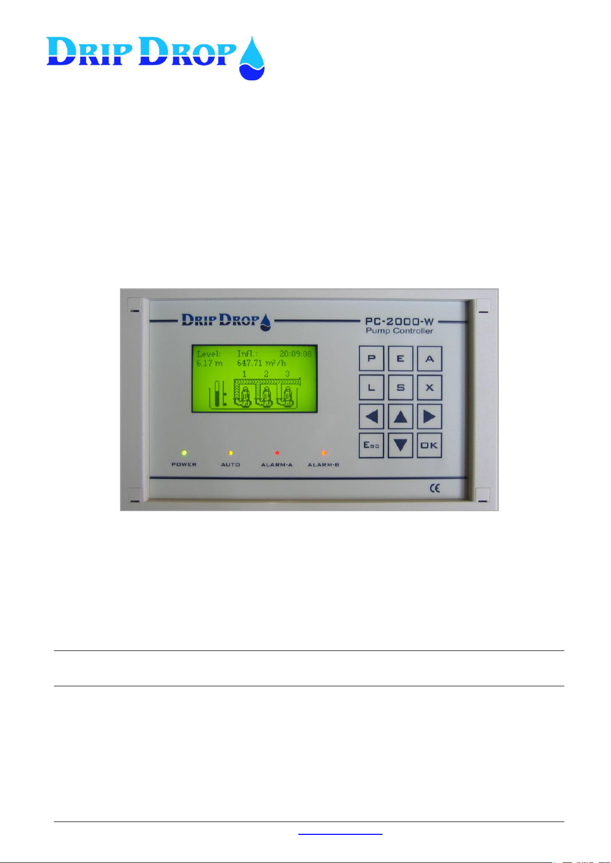
PC-2000-W
Pump controller
User manual
Version 30.56.12/101208-UK
DripDrop AB • Pipers Väg 2C • 170 73 Solna • www.dripdrop.se • Tel. +46 8 655 02 94
Page 2

MANUAL PC-2000-W
Ver. 30.56.12-UK/101208
Page 2 (71)
TABLE OF CONTENTS
1 DESCRIPTION ............................................................................................................................................................ 5
1.1 GENERAL ................................................................................................................................................................... 5
1.2 OPERATOR UNIT ......................................................................................................................................................... 5
1.2.1 Description of the display window ................................................................................................................... 6
2 HOTKEYS AND OVERVIEW SYSTEM SETTINGS ............................................................................................. 7
3 LOG IN – ACCESS CODE ▼ .................................................................................................................................... 9
4 INFORMATION MENUS P , E , A , L , X , ESC , OK , ▲ .................................................................................... 10
4.1 PUMP STATUS KEY P ................................................................................................................................................ 10
4.1.1 Pump information .......................................................................................................................................... 10
4.1.2 Running time and number of starts for pumps. .............................................................................................. 10
4.1.3 Disabling, manual start and stop of pumps.................................................................................................... 11
4.1.4 Display of time delay and service times ......................................................................................................... 11
4.2 SUMMARIZE KEY E ................................................................................................................................................... 12
4.2.1 Actual values .................................................................................................................................................. 12
4.3 ALARM HANDLING KEY A ........................................................................................................................................ 13
4.3.1 Acknowledging new alarms ........................................................................................................................... 14
4.3.2 Active alarms ................................................................................................................................................. 15
4.3.3 Alarm history ................................................................................................................................................. 16
4.4 LOGGER KEY L ........................................................................................................................................................ 17
4.5 EXTERNAL CONNECTED UNITS X ............................................................................................................................. 19
4.5.1 External units that communicate via RS-485 ................................................................................................. 19
4.6 QUICK MENU FOR THE STATUS OF I/O-SIGNALS ESC ................................................................................................ 20
4.7 QUICK MENU FOR THE STATUS OF I/O-SIGNALS OK ................................................................................................. 21
4.8 DISPLAY CONTRAST ▲ ........................................................................................................................................... 21
5 SYSTEM SETTINGS S ............................................................................................................................................. 22
5.1 MAIN MENU ............................................................................................................................................................. 22
5.1.1 How you change the values in the settings menus. ........................................................................................ 22
5.2 APPLICATION TYPE ................................................................................................................................................... 23
5.3 MENU – I/O CONFIGURATION ................................................................................................................................... 24
5.3.1 Digital inputs ................................................................................................................................................. 24
5.3.2 Digital outputs ............................................................................................................................................... 28
5.3.3 Counter inputs ................................................................................................................................................ 29
5.3.4 Analogue inputs (mA) .................................................................................................................................... 30
5.3.5 Analogue outputs ........................................................................................................................................... 32
5.4 PUMP SETTINGS ........................................................................................................................................................ 33
5.4.1 Setting of start and stop levels for pumps ...................................................................................................... 33
5.4.2 Alternation of pumps ...................................................................................................................................... 34
5.4.3 Back-up start .................................................................................................................................................. 34
5.4.4 Max. Running time ......................................................................................................................................... 34
5.4.5 Min. pause time .............................................................................................................................................. 34
5.4.6 Check starts .................................................................................................................................................... 35
5.4.7 Service time .................................................................................................................................................... 35
5.4.8 Random starts ................................................................................................................................................ 35
5.4.9 Running confirmation .................................................................................................................................... 36
5.4.10 Motor current settings ............................................................................................................................... 37
5.4.11 Pump capacity ........................................................................................................................................... 38
5.4.12 Reset motor protection .............................................................................................................................. 38
5.5 STATION SETTINGS ................................................................................................................................................... 39
5.5.1 Alternation ..................................................................................................................................................... 39
5.5.2 Time/delays .................................................................................................................................................... 40
5.5.3 Level alarms ................................................................................................................................................... 41
5.5.4 Cleaning sequences ........................................................................................................................................ 42
5.5.5 Mixer settings ................................................................................................................................................. 43
5.5.6 Flow calculation ............................................................................................................................................ 44
5.5.7 Overflow calculation ...................................................................................................................................... 45
Page 3

MANUAL PC-2000-W
Ver. 30.56.12-UK/101208
Page 3 (71)
5.5.8 Specific energy calculation type .................................................................................................................... 45
5.6 MISCELLANEOUS ...................................................................................................................................................... 46
5.6.1 Operator access code, .................................................................................................................................... 46
5.6.2 Level bar graph .............................................................................................................................................. 46
5.6.3 Logger ............................................................................................................................................................ 47
5.6.4 RS232 settings ................................................................................................................................................ 47
5.6.4.1 Communication settings .............................................................................................................................................. 47
5.6.4.2 Connection settings ..................................................................................................................................................... 47
5.6.5 Setting of RS485-port ..................................................................................................................................... 50
5.6.6 Clock settings ................................................................................................................................................. 51
5.6.7 Reset/Erase .................................................................................................................................................... 51
5.6.8 Factory settings .............................................................................................................................................. 51
6 SMS FUNCTIONS – USING MOBILE PHONE .................................................................................................... 52
6.1 ALARM BY SMS MESSAGES ..................................................................................................................................... 52
6.2 REMOTE CONFIRMATION OF THE ALARMS ................................................................................................................ 52
6.3 SENDING INQUIRIES TO THE STATION BY MOBILE PHONE. ......................................................................................... 53
7 I/O-LIST, SIGNAL TABLE ...................................................................................................................................... 54
8 TECNICAL INFORMATION .................................................................................................................................. 55
8.1 SPECIFICATION PC-2000-W ..................................................................................................................................... 55
8.2 ELECTROMAGNETIC COMPATIBILITY (EMC) ............................................................................................................ 55
9 CONFIGURATION TABLE .................................................................................................................................... 56
10 MENU STRUCTURE – SYSTEM SETTINGS ....................................................................................................... 61
Page 4

MANUAL PC-2000-W
Ver. 30.56.12-UK/101208
Page 4 (71)
Copyright © 2005 DripDrop AB. All rights reserved.
This manual and all the information within may not be copied or reproduced in any form
without the permission of DripDrop AB.
Changes
The content of this manual is for informational use only and can be subject to changes
without prior notice.
DripDrop AB products are developed continuously and we reserve the right to alter technical
specifications without prior notice.
Liability
DripDrop AB assumes no responsibility or liability for errors or incorrect information that may
appear in this document.
DripDrop AB assumes no responsibility or liability for loss of profit, working deficits or any
other indirect losses due to erroneous use or application of the information exposed in this
manual.
Page 5
MANUAL PC-2000-W
Ver. 30.56.12-UK/101208
Page 5 (71)
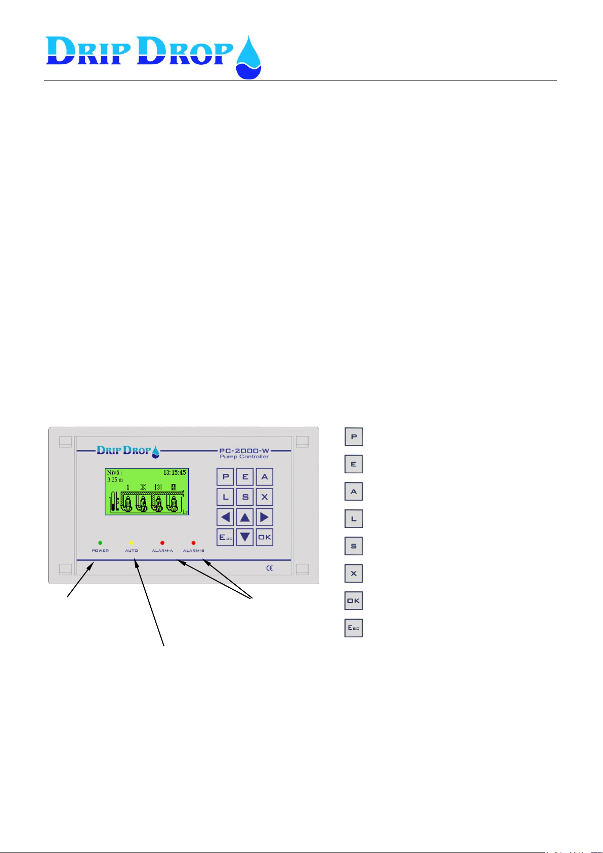
Indacation Pump in Auto
-Blinking yellow light: Pump or pumps not in Auto.
-Fixed yellow light: All pumps in Auto
Indication of A-alarm and B-alarm
-Blinking red light : Not ackn. alarms
-Fixed red light: Active ackn. alarms
Power supply indication
-Fixed green light
Shows pump status, actual and
accumulated data for the last 7 days.
Shows flows and overflows, actual and
accumulated values for up to 7 days.
Shows unconfirmed, active alarms and
alarm history.
Shows logged values, numeric and graphic
Menu where all basic settings are made for
example start- /stop levels, alternation etc.
Shows external units that can communicate
via RS-485.
Push button used to confirm choice and to
enter sub menus.
Close menus and step backwards.
1 Description
1.1 General
The pump controller PC-2000-W is an advanced computer controlled device to control and supervise
up to 4 pumps. Containing an operator unit (CPU unit PC-2000-W) and an I/O unit
(ADA 2000-E) for connecting digital and analogue signals.
The signals transfer between the units via three flat cables.
The unit has two communication ports RS 232 / 485 for communication with a supervision and
SCADA system or for serial communication with other units.
1.2 Operator unit
The operator unit is mounted in the front door of a cabinet and has 12 control keys for
configuration and alarm handling. The graphic 64 x 128 dot display shows information,
log values and historical log as curves.
Page 6
MANUAL PC-2000-W
Ver. 30.56.12-UK/101208
Page 6 (71)
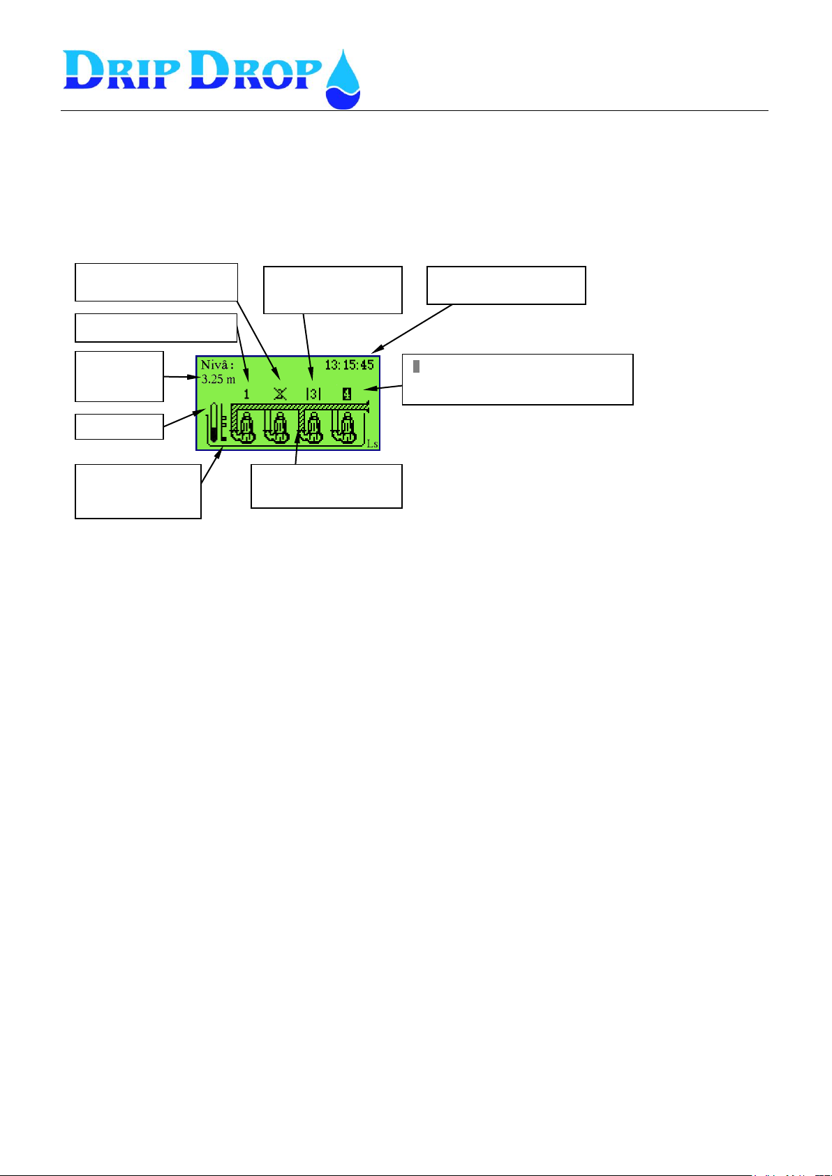
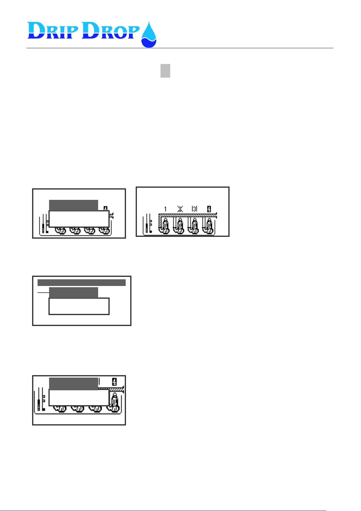
Actual level if
sensor is
connected
Level bar
Indicates level floats
and if they are
On /Off.
Movement in pipe shows
that pump is running.
1 – Indicates that pump is OK
X – Indicates that a timer is
counting.
|3| - Indicates that
pump is in Not auto
pos.
Tme and Date toggles
every 15 sec.
4 – Indcates that pump is blocked. For ex
by motor protec tor, low motor current etc.
1.2.1 Description of the display window
The back lit display shows the number of pumps in the pit and their status, water level- graphic and
numerical, in- and outflow, date/time, level switch and their status. Normally the display light is off,
but will light up when any key is pressed. The display light will shut off after 5 minutes of inactivity
Running Pump – When a pump is running, it is indicated by water running in the pipe.
Waiting mode – if a time delay or another time function is activated, it is shown by an X over the
pump number. This is to show that the pump waits for a time function before the pump is ready to
restart.
Not in Auto – indicates that pump selector switch is not in Auto position. This is shown by two
vertical lines |3|, and that the yellow Auto LED starts to blink.
Blocked Pump – certain circumstances blocks the restart of the pumps, for example certain alarms or
causes where you choose that the pump will be blocked when an error occurs. A Blocked
pump is indicated by a grayed out pump number. The blocking can be lifted by fixing the
fault and acknowledge the alarm.
Page 7
MANUAL PC-2000-W
Ver. 30.56.12-UK/101208
Page 7 (71)
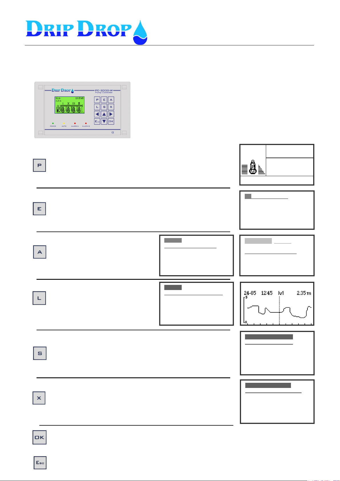
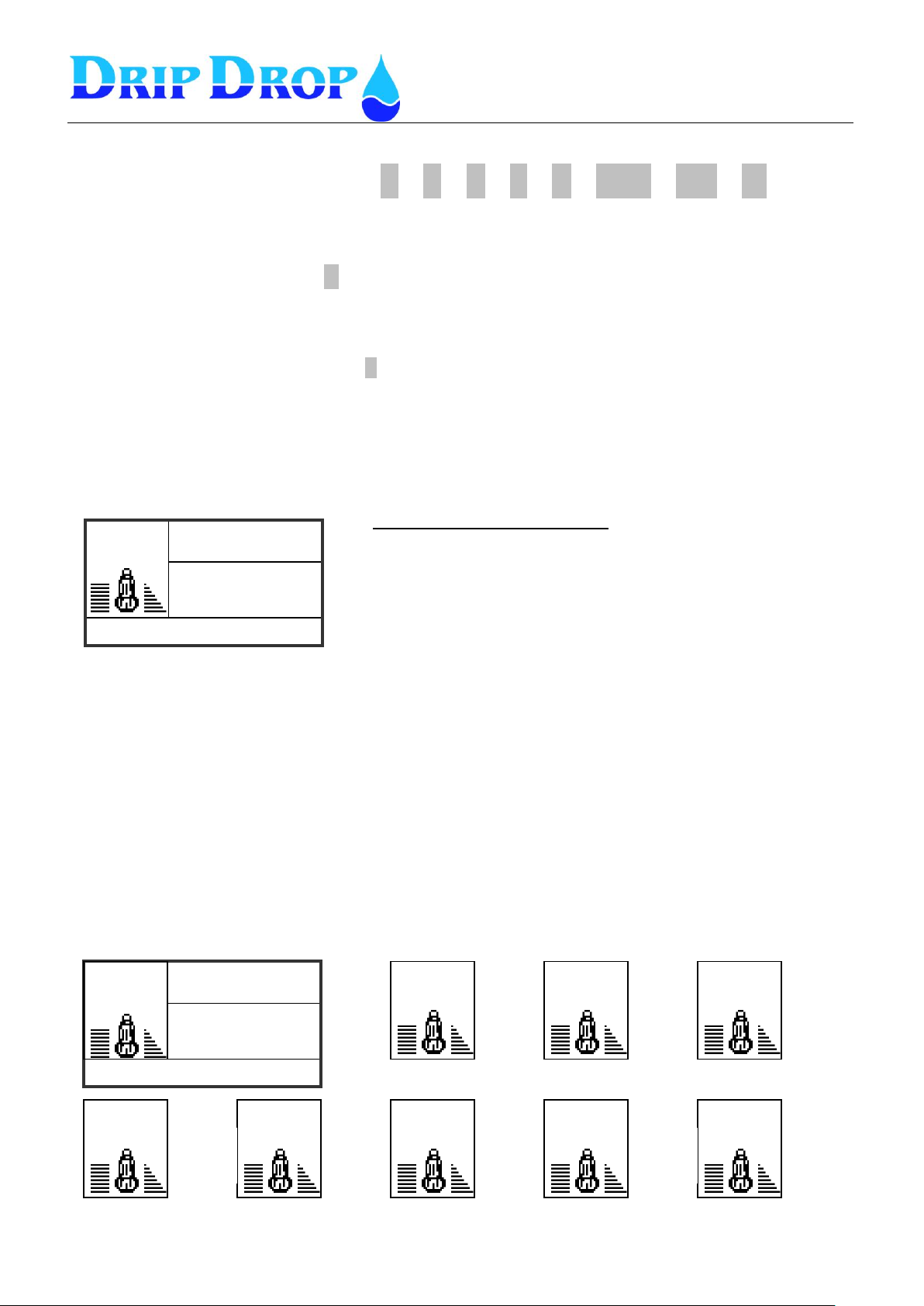
Shows pump status, actual total values as well as data up to 7 day
back. More info in chapter 4.1.
Shows flows, overflows, power and energy if the corresponding
meters are used. Actual and ackumulated values for up to 7 days
are shown . More info in chapter 4.2.
Shows unconfirmed, active alarms and
alarm history. When you enter the
alarm menu you can choose to see not
acknowledge alarms, active alarms and
a alarm history list with up to 200
alarms. More info in chapter 4.3.
Shows logged values up to 7 days.
There is one display for numeric values,
all values can also be displayed as
curves in the display window.
More info in chapter 4.4.
Menu where all basic settings are made for pumps, station and
communication, for example start- /stop levels, alternation a.s.o.
More info in chapter 5.
Shows status and information from external units that are
connected via the RS-485 port. Up to 6 units can be connected to
one PC 2000 W More info in chapter 4.5.
Push button used to confirm choice and to enter sub menues.
Close menus and step backwards in the menustructure
Cap.[m3/h] 0.0
Current[A] 25
Level[m] 1.45
Off
Time 2:16:03
Starts: 58
Pump 1
Total
η ______________Now
Flow-c: 0.0 m3/h
Power: 0.0 kW
Efficiency: 0.0Wh/m3
Not ack. alarm 001/001A
Level alarm
LOW lEVEL .
Time on:09/o1/21 18:57:05
Time off:06/11/21 18:59:08
Alarms
.
▪ Not ack. alarms
▪ Active alarms
▪ Alarm history
Settings( ) V30.56.XX
______________________
▪Application type
▪I/O Configuration
▪Pump settings
▪Station settings
▪Miscellaneous
EXT 1-PC 2000 screens
Link: ____________________
Alarms:0
Level[m]:
AI2[]:
Current P1
Logger yy-mm-dd
19:30
Level: 1.45 m
Inflow: 0.00 m³/h
Outflow: 0.00 m³/h
Overflow: 0.00 m³
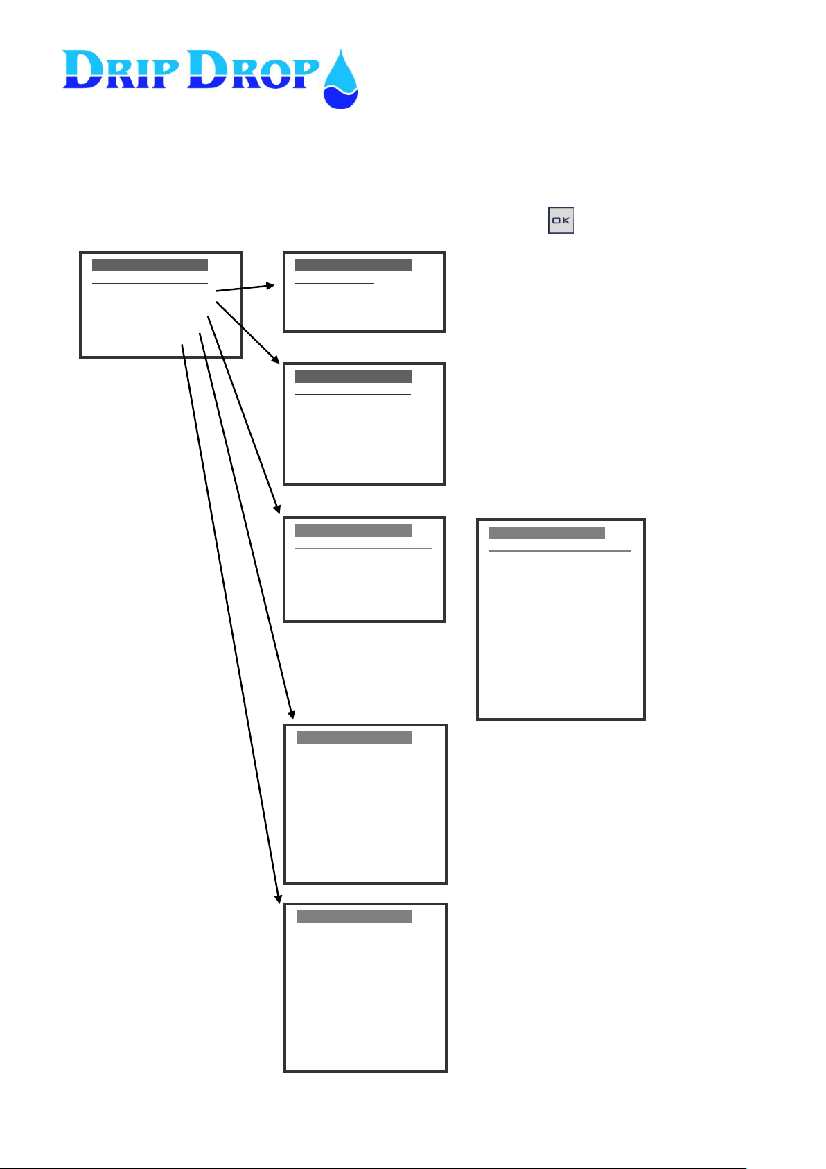
The pumpcontroller PC 2000 W uses an extensive menu to display
and handle information as well as configuration of the unit directly
from the display panel. In order to get to better understand all menu
functions, here follows a brief overwiev of the structure of the
different menues for status, information and configuration.
Through the P,E,A,L and X keys you will access status and
information regarding pumps and the pumping station. The S key is
to enter into the menu structure where all configurations are made.
2 Hotkeys and Overview system settings
Page 8
MANUAL PC-2000-W
Ver. 30.56.12-UK/101208
Page 8 (71)
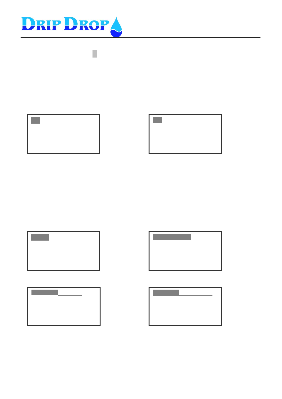
Settings( ) V30.56.XX
______________________
▪Application type
▪I/O Configuration
▪Pump settings
▪Station settings
▪Miscellaneous
Settings( ) V30.56.XX
I/O Configuration_____
▪Digital inputs
▪Digital outputs
▪Counters
▪Analogue inputs
▪Analogue outputs
Settings (Ls)v30.56.xx
Station settings______
▪Alternation
▪Time/Delays
▪Level alarms
▪Cleaning sequencies
▪Mixer 1 settings
▪Mixer 2 settings
▪Inflow calculation
▪Overflow calculation
-Spec. Cons.: Flow-c
Settings (Ls)v30.56.xx
Miscellaneous_______
-Op. access code:▼ ▼ ▼ ▼
-Sys. Acces code: ▲ ▲ ▲ ▲
▪Level bargraph
▪Logger settings
▪RS232 settings
▪RS485 settings
▪Clock settings
▪Reset /Erase.
▪Default settings
Settings (Ls)v30.56.xx
Pump settings_____________
▪Pump 1
▪Pump 2
▪Pump 3
▪Pump 4
Settings( ) V30.56.XX
Application ___
- Number of pumps: 2
- Max. Running pumps: 1
- Start float: No
Settings (Ls)v30.56.xx
Pump 1_____________________
▪Day time levels
▪Night time levels
-Alternation : Yes
-Back-up start: No
-Max. runtime [min]: 240
-Min breaktime [s]: 10
-Check after[h]: 0
-Check for[s]: 0
▪Servcice time
-Random Starts[cm]:
▪Running confirmation:
▪Pump capacity
▪Reset Protection
►
Application menu – to set how many pumps
you have in the station, how many pumps are
allowed to run simultaneously and if you use
level sensor or level switches to detect
operating levels.See chapter 5.2
I/O configuration menu – is where you
define how to use all predefined inputs and
outputs, digital and analogue.
See chapter 5.3
Pump settings menu-
This is where you set all
parameters regarding
each individual pump,
start/stop levels,
alternation, current
settings etc.
See chapter 5.4
Station setting menu- This is the menu for
setting of station specific parameters.
Alternation type, timers and delays, alarm
levels, mixing and cleaning functions,
flowcalculation functions etc.
See chapter 5.5
Miscellaneous menu – In this menu you can
make settings for access codes, logger
settings, all communication settings, reset/
erase alarmlists/counters and reset the unit to
original factory settings.
See chapter 5.6
Settings menu - overview
The Settings menu is where all the configuration of the unit is made. By pressing the S key, you
will enter the Settings main menu that consists of five submenus handling different areas in the
configuration process. You enter each submenu by moving up and down in the menu options with
the ▼▲ key, and enter the corresponding submenu by pressing the key.
Page 9
MANUAL PC-2000-W
Ver. 30.56.12-UK/101208
Page 9 (71)
Level: yy-mm-dd
1.45 m
|
Log in
Settings( ) 20.54.42
.
-Función: |en uso
-Tipo señal: NC
-Tipo Alarma: alarma-A
-Delay[s]:
|
Log in
Nivel: yy-mm-dd
1.45 m
Are you sure?
Log out
When you are logged in the
following will show up in the
lower right corner of the
display :
Ls (system)
Lo ( operator).
Level: yy-mm-dd
1.45 m
Ls
3 Log in – Access code ▼
In the information menu, you will find all information about pumps, logged values and alarms. To
make changes or to acknowledge alarms you need an access code depending on what you like to do.
The unit has two different access levels:
1. Operator code- that allows acknowledgement of alarms.
2. System code –which allows changing of all values and configuration of the unit.
The access codes can be changed under Settings/Miscellaneous
There are two ways to enter the access code:
1. From the main display picture by pressing the ▼ key you will enter the access code prompt. Here
you can enter the valid code and confirm by pressing the OK key.
2. When you are in a sub menu and try to enter the edit position by pressing OK, you will come to the
access code prompt. When the prompt shows, you have to enter the valid access code. You can then
enter the edit position where you can change the values.
The unit will log out automatically 5 minutes after inactivity.
As an alternative, you can press the ▼key and the log out prompt will show. Press OK .
Page 10
MANUAL PC-2000-W
Ver. 30.56.12-UK/101208
Page 10 (71)
Cap.[m3/h] 0.0
Current[A] 25
Level[m] 1.45
Off (A)
Time 2:16:03
Starts: 58
Pump 1
Total
Off
Cap.[m3/h] 0.0
Current[A] 25
Level[m] 1.45
Time: 2:16:03
Starts: 58
Information window for Pump 1
Specific information for each pump.
Actual values that are shown in all pump status windows.
Information about if a pump is running or not, if a pump is
in automatic mode and if the pump has stopped becaue
of an alarm.
Pump 1
Total
Pump 1
Today
Press
►
Press
►
Pump 1
-1 Day
Press
►
Pump 1
-2 Day
Press
►
Pump 1
-3 Day
Pump 1
-4 Day
Pump 1
-5 Day
Pump 1
-6 Day
Pump 1
-7 Day
Press
►
Press
►
Press
►
Press
►
Picture 1
4 Information menus P , E , A , L , X , ESC , OK , ▲
To access information about pump status, alarms and station values quickly, you use the information
hot keys on the front panel.
4.1 Pump status key P
4.1.1 Pump information
The P key is used to get information about each pump quickly. You can access three pump
information windows by pressing the P key
The first window shows total values for running time and number of starts for the pump. This
information is given only in this window.
All other information is shown in the two following windows.
You scroll thru pump 1-4
with the ▲▼ keys.
To the right and left, between day1-7,
and total values for each pump with◄►
When you are in the information window, you scroll thru the information for pump 1-4 with the
▲▼keys.. This stepping between the pumps can be made in all information windows. You will
always get into the corresponding window for next pump.
4.1.2 Running time and number of starts for pumps.
To see running time and number of starts for pumps you press the P key. To see the values for the
other pumps press the ▲▼ keys. By pressing the ► key, you will see actual running time and number
of starts. Pressing the ► key scrolls thru the last seven days. After 7 days, you will get back to total
values.
Corresponding information for pumps 1-4 is shown by pressing the ▲▼keys.
Page 11

MANUAL PC-2000-W
Ver. 30.56.12-UK/101208
Page 11 (71)
Off
Cap.[m3/h] 0.0
Currentr[A] 25
Level[m] 1.45
** Pump disable
-----------
Pump 1
Total
Picture 2 under P key
When you enter this picture the cursor will be in the
position ”Pump disable”. If you want to disable the pump press the
OK key.
Off
Cap.[m3/h] 0.0
Current[A] 25
Level[m] 1.45
** Pump disable ?
------------
Pump 1
Total
Now a question mark will appear after the disable prompt. Press OK
to confirm.
Disabled
Cap.[m3/h] 0.0
Current[A] 25
Level[m] 1.45
** Pump enable
------------
Pump 1
Total
When you have confirmed the text ”Pump enable ” will appear.
If you want to enable the pump press OK as above.
You can see that the pump is disabled in the status window at the
bottom of the display.
Off (A)
Pump 1
Total
Cap.[m3/h] 0.0
Current[A] 25
Level[m] 1.45
Delay.[s]: 10
Service[h]:06000:00
Picture 3 under P key
In this window you will see if a timer is counting down.
This example shows that it is 10 seconds left until the count down is
ended.
You can also see that there are 6000 hours left to the next
maintenance check for the pump.
Picture 2
4.1.3 Disabling, manual start and stop of pumps.
When a pump is removed for service, you can disable the pump in the controller.
When you disable a pump, the pump will disappear from the main picture.
To reach the disabling position you press the P key twice.
Picture
4.1.4 Display of time delay and service times
In picture 3 under the P key you will see if the unit is counting down on a time delay, for ex. start or
stop delay or similar. This is shown by the remaining time that is counting down in the window under
Delay. If the counter shows zero, it is not counting. If a time is counting down this may be the reason
that a pump does not start until the time is finished. If the function for service time is activated you
will see how long time is left until the next scheduled maintenance of the pump.
Page 12
MANUAL PC-2000-W
Ver. 30.56.12-UK/101208
Page 12 (71)
η ______________Now
Flow-c: 0.0 m3/h
Power: 0.0 kW
Efficiency: 0.0Wh/m3
Overflow_______Now
Time: 0:00:00
Number:
Flow:
Level:
Status:
η _ ____________Total
Volume-c: 0.0 m3
Power: 0.0 kWh
Efficiency: 0.0 Wh/m3
Overflow Total
Time:
Number
Flow:
Level:
Status:
Flow Now
Inflow 0.0 m3
Outflow: 0.0 m3
Flow-AI2 0.0 m3
Rain flow: 0.0 l/s*ha
Power: 0.0 kW
Ackumulated _ Total
Inflow: 0.0 m3
Outflow: 0.0 m3
Flow-AI2 0.0 m3
Rain flow: 0.0 l/s*ha
Power: 0.0 kW
Press
►
Press
►
Press
►
4.2 Summarize key E
4.2.1 Actual values
The E-key is used to see the actual values, total values and the values for the last 7 days for efficiency,
flow and overflow.
When you press the E-key once if energy meter is used you will come to efficiency. If not you will go
directly to the flow display. When you press the E-key a second time you will come to flow and when
you press the E-key a third time you will come to overflow.
When you are in the Efficiency display, the actual values are shown first. When you press the key ►,
you will come to the total values. When you press the ► key once more, you will come to the values
for today. In the same way, you continue for the values for 7 days back. This is valid for flow as well
as overflow.
If you want to go back to previous values press ◄ key.
Page 13
MANUAL PC-2000-W
Ver. 30.56.12-UK/101208
Page 13 (71)
Not ack. alarm 001/001A
Level alarm
LOW lEVEL .
Time on:09/o1/21 18:57:05
Time off:06/11/21 18:59:08
Example of alarm in the text window.
Not ack. alarm 001 of 001 alarms in the alarm list A-larm.
That it is a level alarm (has to do with the level measurement)
The alarm is a low level alarm
Time when the alarm got active started.
Time when alarm got inactive.
ALarms
.
▪ Not ack. alarms
▪ Active alarms
▪ Alarm history
Alarm handling menu – here you can see the different alarms
Not ack. alarms (new) .
Active alarms
Allarm history
With the up and down keys you can chose which type of alarms you
want to see and enter the alarm list with the OK key.
4.3 Alarm handling key A
The pump controller PC-2000-W has the capacity to handle a great number of different alarms for
pumps, station and even internal alarms. Every alarm generates an information window when
activated, with information about which alarm is activated, activation time and if it is an A or B-alarm.
At the same time, one or two alarm LEDs is blinking until the alarm is confirmed.
5 minutes after the alarm text is shown on the screen the screen light go off and the alarm text
disappears.
The alarms are then indicated via the two alarm LEDs.
Blinking red light indicates a new alarm, which is not confirmed.
Fixed red light indicates that the alarm is confirmed but still active.
There are two types of alarms. A-alarms and B-alarms.
A-alarm is an alarm that calls a supervision system or sends a text message to a mobile phone.
B-alarm is an alarm that only is registered in the alarm history but is not sent to an external system.
This text is shown in the display window when the alarm starts, but will disappear after 5 minutes
when the screen light is shut down. When the screen is shut down, you will see that there is an alarm
in the alarm list by the two alarm LEDs. To access the alarm you press the A key to enter into the
alarm handling menu:
Page 14
MANUAL PC-2000-W
Ver. 30.56.12-UK/101208
Page 14 (71)
Not ack.alarm 001/003A
Level alarm
NIVEL BAJO .
Time on:06/11/21 18:57:05
Time off: 06/11/21 18:59:08
Log in
Alarm
.
▪ Not ack. alarms
▪ Active alarms
▪ Alarm history
Not ack. alarm 0001/003A
Level alarm
LOW FlOAT ON .
Time on: 09/03/24 18:57:05
Time off:09/03/24 18:59:08
The log in promt will not show up if you are already logged in to the
system. .
Not ack. alarm.
No alarms .
Time on:
Time off:
4.3.1 Acknowledging new alarms
New alarms are indicated by the blinking of one of the red alarm LEDs. To acknowledge the alarms
you have to enter Not ack. alarms option in the alarm menu.
When you are in the alarm list for Not ack. alarm, you can acknowledge the alarm by pressing the OK
key. If there are more Not acknowledged alarms in the list, you can step through the list with the up
and down keys.
When all alarms are acknowledged, the red LED stops blinking and the display will show that there
are no alarms in the list. If the alarm is still active the LED show a red fixed light.
If you have not logged in the Log In prompt will show when you press the OK key to acknowledge the
alarm.
When you have acknowledged all alarms that you want to acknowledge you quit the alarm handling
function by pressing the Esc key until you have returned to the main menu.
Page 15
MANUAL PC-2000-W
Ver. 30.56.12-UK/101208
Page 15 (71)
Alarms
.
▪ Not ack. alarms
▪ Active alarms
▪ Alarm history
Active alarms
▪*Pump failure
▪*Sensor failure
▪ System alarms
▪*All alarms
In this menu you can look at all alarms or alarm groups.
Groups with active alarms are indicated with an asterics.
You enter the different alarm groups with the OK key.
Active alarm 001/003A
Level alarm
LOW LEVEL .
Alarm on:09/03/24 18:57:05
Alarm Ack:09/03/24 18:59:08
Example of active alarms in the alarm list
Shows which alarm is shown, in this case 1 of 3.
Alarm type, A-alarm.
Alarm group – Level alarm
Alarm – Low level alarm
Time when the alarm started.
Time when the alarm was acknowledged.
4.3.2 Active alarms
If you want to see active alarms, you choose active alarms in the alarm handling menu.
When you enter active alarms you come into a submenu where you can chose to look at all alarms or
just pump alarms, sensor alarms or system alarms.
When you are in the alarm list for active alarms, you can see information about number of alarms in
the list, alarm type and time when the alarm started and when it was acknowledged. The alarm shown
when you enter the list is the latest alarm.
To step forward backwards in the alarm list use the up and down keys.
When you are ready with the alarm handling you exit with the Esc key.
Page 16
MANUAL PC-2000-W
Ver. 30.56.12-UK/101208
Page 16 (71)
Alarms
.
▪ Not ack. alarms
▪ Active alarms
▪ Alarm history
Alarm
▪*Pump failures
▪ Sensor failures
▪ System alarms
▪ All alarms
History alarms 001/003A
Level alarm
LOW level .
Alarm on:09/03/24 18:57:05
Time ack.;09/03/24 18:59:08
Alarm off:09/03/24 20:12:33
In this menu you can look at all alarms or look at alarms in different
alarm groups.
Groups with stored alarms are indicated with a star.
You enter the alarm groups with the OK key.
Example of alarm in the alarm history list
Shows which alarm is shown, in this case 1 of 3.
Alarm type, A-alarm.
Alarm group – Level alarm
Alarm – Low level alarm
Time when alarm started .
Time when alarm was acknowledged.
Time when alarm stopped
4.3.3 Alarm history
In the alarm history, all alarms for up to 200 alarms are listed. When the list is full, the oldest will
disappear.
To enter the alarm history you chose alarm history in the alarm-handling menu.
Even in the submenu, you can chose between all alarms or chose alarms in groups the same way as in
the active alarms menu.
In the alarm history list, you will find all registered alarms. The latest alarm is the first in the text
window and the oldest is at the bottom, maximum 200 alarms can be stored in the history list.
Page 17
MANUAL PC-2000-W
Ver. 30.56.12-UK/101208
Page 17 (71)
Logger yy-mm-dd
19:30
Level: 1.45 m
Inflow: 0.00 m³/h
Outflow: 0.00 m³/h
Overflow: 0.00 m³
Logger yy-mm-dd
19:30
Flow-AI2: 0.00 l/s
Rain flow: 0.0 l/s*ha
Power: 0.0 kW
Logger yy-mm-dd
19:30
I1: 25.00 A
I2: 25.00 A
I3: 0.0 A
I4: 0.0 A
Logger yy-mm-dd
19:30
Pump1:Disabled (A)
Pump2:Off (M)
Pump 3:Disabled (A)
Pump 4:Disabled (A)
Picture 3.3 The four logger windows.
4.4 Logger key L
Logged values are stored in the PC-2000-W in 1 to 10 minutes intervals and displayed as average
values for 7 days. All logged information is found by pressing the logger key L. There are four
different windows available by pressing the L key.
Main window for logger
Below you can see the four logger windows.
Each time you press the L key you step to the next window.
Time selection for logger values.
In all logger windows, the time is shown in the upper right corner of the logger windows and shows
the time for the values. If you press the ◄ key once you will see, the logged values according to the
time interval 1-10 minutes for each time you press the◄ key you move one time interval backward in
time. If you keep the ◄ key pressed for a couple of seconds you will get intervals of 15 minutes.
If you press the key for more than 10 seconds, the time interval will be 1 hour.
For movement forward you use the ► key the same way.
Page 18
MANUAL PC-2000-W
Ver. 30.56.12-UK/101208
Page 18 (71)
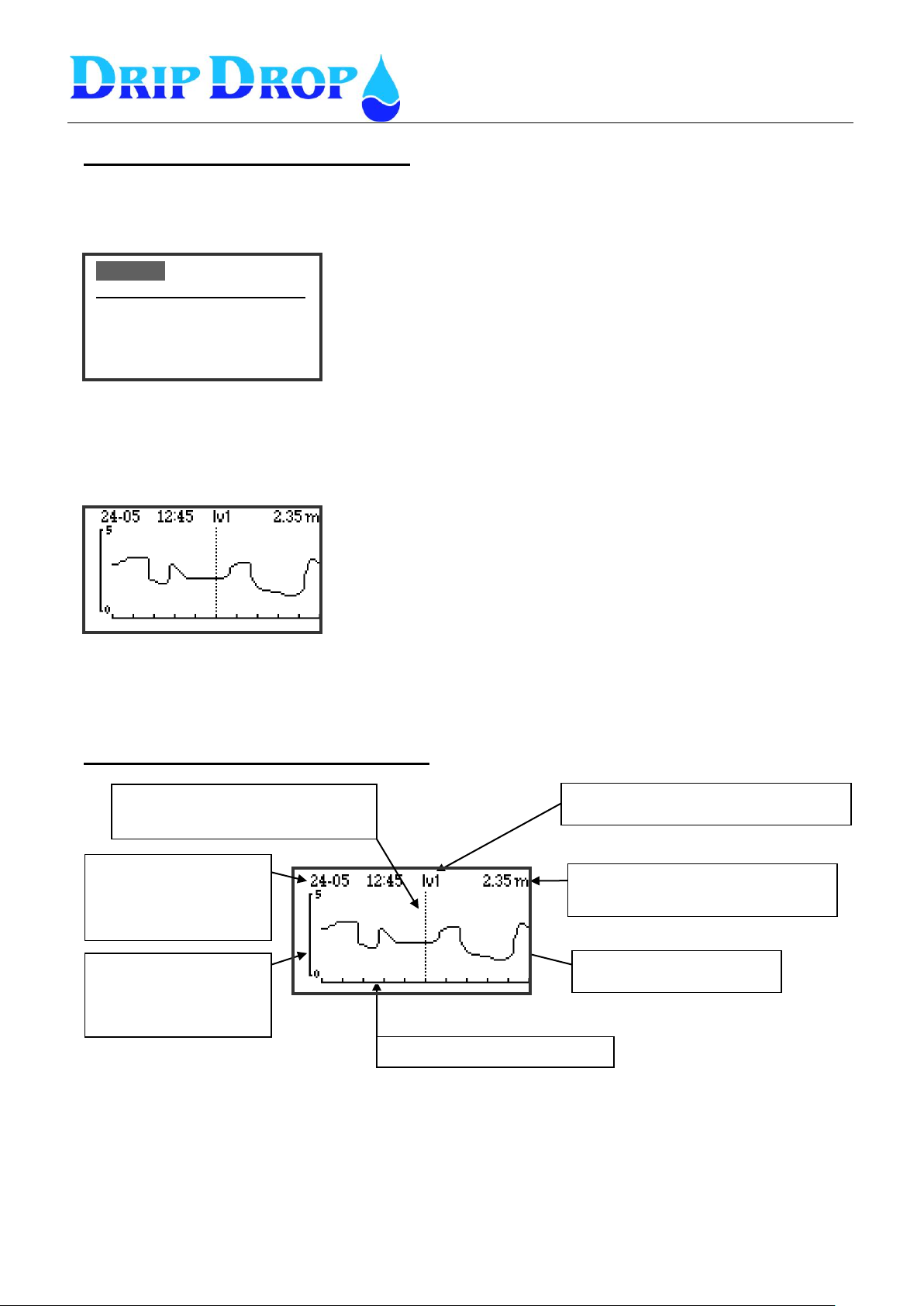
Time reference line equals the
time shown in the window.
Registered value at shown time.
Automatic scaling,
based on registered
min. and max. values.
Time scale, shows 10 hours
Average curve is shown.
Parameter shown in the window.
Logger yy-mm-dd
19:30
Level: 1.45 m
Inflow: 0.00 m³/h
Outflow: 0.00 m³/h
Overflow: 0.00 m³
Enter the logger window by pressing the L key.
Press OK key to enter graphic display.
After a couple of seconds the first value in the list, in this case the
level, is shown as a curve
To see the other curves in the logger list you use the▼▲ keys to
change viewed parameters to the next one in the logger list.
To get back to numeric values you press the Esc key.
Time indication, shows
the actual time at the
reference line.
Visualizing of log values in graphic form
All values that are shown in the logger window can be viewed as a graphic curve. This is done by
entering the logger window, which holds the information you are interested in and press the OK key.
The unit will process the information during a couple of seconds and the display the values as a curve
in the logger window, in this case, the level is shown.
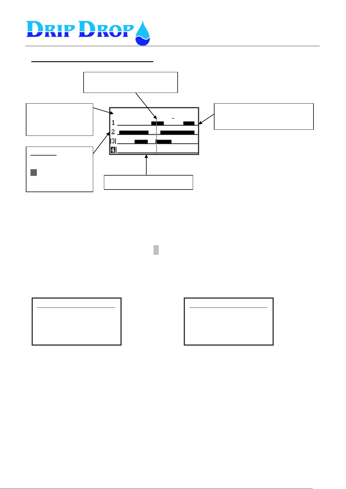
Because you log both analogue and digital values, you will see two different graphic displays, usual
curves and bar graphs.
Description of the analogue display window
To move along the time axis use the ◄► keys.
Page 19
MANUAL PC-2000-W
Ver. 30.56.12-UK/101208
Page 19 (71)
11-22 20:20 pump status
Pump info
1 = All OK
|1| = Not in auto
1 = blocked
X= in waiting pos.
Time reference line equivalent to
shown time in display
ON and OFF status for pumps.
Black staple = ON
No staple = OFF
Time scale shows 10 hours
1.PC 2000:2_____________
Link: OK
Alarm: 0
Level[m]: 0.00
Current P1[A]: 0.00
Current P2[A]: 0.00
2.PC 2000:1_____________
Link: OK
Alarm: 0
Level[m]: 0.00
Current P1[A] 0.00
Current P2[A] 0.00
Press
►
Press
►
Device 1
Device 2
Time indication,
shows the actual time
at the reference line.
Description of the digital display window
To move along the time axis use the ◄► keys.
4.5 External connected units X
4.5.1 External units that communicate via RS-485
The X-key shows the external RS485 connected devices and the values they are set to display.
Press Esc to return to main menu
By pressing the X key the first 485 device connected will be displayed. If more than one 485 devices
are connected, you will see next device by pressing the ►key. By pressing the ▲▼ keys, you can
access and look at the whole list of connected 485 devices.
Page 20
MANUAL PC-2000-W
Ver. 30.56.12-UK/101208
Page 20 (71)
Digital inputs
Digital outputs
UtUtgångar
Analogue inputs
A1: 4.00 A5: 0.00
A2: 4.00 A6: 0.00
A3: 0.00 A7: 0.02
A4: 4.00
Analogue outputs
AO1: 4.0 0 mA
AO2 : 0. 00 V
Daily
CI 1 : 0 (Off)
CI 2 : 0 (Off
Press
▼
Press
▼
▪ ■ ▪ ▪ ▪ ▪ ▪ ▪ ▪ ▪ ■ ▪ ▪ ▪ ▪ ▪ ▪ ▪ ▪ ▪
▪ ▪ ▪ ▪ ▪ ▪ ▪ ▪ ■ ▪ ▪ ▪ ▪ ▪ ▪ ■
1 5 10 15 20
1 5 10 15
By pressing the ▼key, you will enter the analogue input status
window, where the real unscaled mA values will be shown on all
analogue inputs.
NOTE! Real mA values
Press
▼
By pressing the Esc key you enter the graphic display mode for the
status of digital inputs and outputs.
Active in/outputs are indicated by a dark rectangle at the input/output
number.
By pressing the ▼once more key, you will enter the analogue output
status window, where the real unscaled mA and Voltage values will
be shown on the analogue outputs.
By pressing the ▼key once more, you will enter the daily counter
status window, where the daily real pulse number will be shown.
NOTE! Real counted pulses today.
If the pulse counter does not receive any pulses this will be indicaded
by the (Off) indication.
4.6 Quick menu for the Status of I/O-signals Esc
The Esc-key is used to see the status of the digital in- and outputs. When the status is active, this is
shown with a square instead of a point in the display. There are 20 digital inputs and 16 digital outputs,
7 analogue inputs, 2 analogue outputs and 2 counters.
To change between the different input and output displays with the key ▼.
Page 21
MANUAL PC-2000-W
Ver. 30.56.12-UK/101208
Page 21 (71)
Level: yy-mm-dd
1.45 m
Min Max
CONTRAST
Menu picture digital inputs
Shows a list with all digital inputs of the unit. If they are used,
configured signal type and if they are active or not
--- means that the input is not used.
NO or NC means that the input is used and that it is used as NO
(normally open) or NC (normally closed).
If the signal is shown with shaddow NO it means that the input is
active.
Menu picture digital Outputs
This list shows all digital outputs, which are used
and if they are active or not.
--- means that the input is not used.
NO or NC means that the input is used and that it is used as NO
(normally open) or NC (normally closed).
If the signal is shown with shaddow NO it means that the input is
active.
Menu picture analogue inputs
Shows list of all analogue inputs.
Values shown are all scaled according to configuration.
Digital inputs
1.Low float: NO
2.High float: NO
3.Overflow switch: NO
4.P1 Not in Auto: NC
:Digital outputs
1.P1 Start/Stop: NO
2.P1 Reset M.Protect --
3.P2 Start/Stop: NO
4.P2 Reset M.Protect --
Analogue inputs
1.Level Sensor: 1.55
2.Flow meter: --
3.P1 Motor current: 24.4
4.P2 Motor current: 35.0
You move up and down
in the menu with the ▲▼buttons
You move up and down
in the menu with the ▲▼buttons
You move up and down
in the menu with the ▲▼buttons
4.7 Quick menu for the Status of I/O-signals OK
In this menu you see the actual values and status of the in- and outputs fast, in table format.
In order to see the status of the in- and outputs fast you press the OK button. You come directly to the
menu picture for digital inputs. If you press the OK button once more, the digital outputs will be
shown. By pressing the Ok button once more, the analogue inputs will be shown. This is a loop where
you go from digital in, digital out analogue in. For analogue inputs, the scaled values are shown.
Press OK button to go to Digital Outputs.
Press OK button to go to analogue inputs, which shows scaled values.
To return to main menu press Esc.
4.8 Display contrast ▲
The ▲ key is used to enter the position where you can change the contrast in the display.
This is done by using the ◄► keys.
Page 22
MANUAL PC-2000-W
Ver. 30.56.12-UK/101208
Page 22 (71)
How you move within the menus?
All menu alternatives with a ■ symbol in front have sub menus which
you can enter.
Alternatives with a – sign in front means that you have reached
the level were settings can be made.
To move in the menus you use the arrow keys up and down ▼▲.
To enter the menu you use the OK key.´
To exit the menu you use the Esc key.
Settings( ) V30.56.XX
I/O Configuration__________
▪Digital inputs
▪Digital outputs
▪Counters
▪Analogue inputs
▪Analogue outputs
ettings V30.56.XX
Digital inputs__________
01. Low float
02. High float
03. Overflow
04. P1 Not in Auto
05. P1 Motor Protect
06. P1 Temp. Protect
Sub menu In- and Outputs
You enter the sub menu by pressing the OK key.
The example shows the sub menu for in and outputs.
Sub menu digital inputs
You enter the submenu by pressing the OK key.
In the example the digital submenu for digital inputs is shown
Settings ( ) V30.56.XX
▪Application type
▪I/O Configuration
▪Pump settings
▪Station settings
▪Miscellaneous
Main menu – description.
Application type – here you set how many pumps the
pumpingstation has and how many pumps are allowed to run at the
same time.
I/O configuration - here you define how the in and outputs shall be
handled.
Pump settings – here all settings for each pump are made, for ex,
start and stop levels, alternation etc.
Station settings – here all setting for the station are made, for
example alarm levels, mixer functions, in/outflow calculations.
Miscellaneous – here are all other settings made, factory settings,
communication settings, resetting of counters etc.
Settings( ) V30.56.XX
▪Application type
▪I/O Configuration
▪Pump settings
▪Station settings
▪Miscellaneous
5 System settings S
PC-2000-W has a factory default setting for a quick start with most normally used functions activated.
To adapt the PC-2000-W to the actual location you might have to activate more I/Os and configure
functions accordingly.
5.1 Main menu
The settings menu is divided into logically grouped submenus. You enter the settings menu by
pressing the S key (settings).
Here we will describe how you enter the different sub menus and how you can change the values.
It is convenient when configuring the unit to follow the logic structure of the menus.
5.1.1 How you change the values in the settings menus.
Here we show how you move in the menus and how you change the values by choosing different
alternatives and numeric values.
Page 23
MANUAL PC-2000-W
Ver. 30.56.12-UK/101208
Page 23 (71)
Menu – Applications type
Here you set how many pumps there are in the station
Here you set how many pumps that are allowed to run at the
same time.
<- Here you decide if the station work with floats instead of a level
sensor .
No = Function with level sensor 4-20 mA.
Yes = Function with floats.
Settings( ) V30.56.XX
01. Low float
-Function:| in use
-Signal type: NC
-Alarm type: B-alarm
-Delay on/off[s]:1
Changing of values – text alternative.
When you have reached the menu were you can change the text
(indicated with – symbol) you chose the parameter you want to
change and press the OK key.
Now the cursor will blink in front of the value to be changed. Scroll
through the alternatives with the ▲ key and accept the desired
alternative by pressing the OK key.
Changing of values – numeric values.
When you have reached the menu were you can change the text
(indicated with – symbol) you chose the parameter you want to
change and press the OK key.
Now the cursor will blink in front of the value to be changed. Put the
cursor in front of the value to be changed with the ◄► keys,
change the numeric value by using the ▲▼ keys. Accept the
change by pressing the OK key.
Settings ( ) V30.56.XX
Application type ___
-Number of pumps : 4
-Max. Running pumps: 2
-Start float: No
Settings ( ) V30.56.XX
Application type
-Number of pumps : 2
-Max. Running pumps: 1
-Stop float: Yes
-Stop way: Sequential stop
General stop
Own float stop
Sub menu – float switch control
When you activate the function float, control the pumps will start
with the corresponding start level switch, but you have 3 alternatives
on how to use the level switches to stop the pumps.
Sequential stop– If you have more than one working pump each
pump will stop when the starting float of the previous pump is
reached, the last working pump will stop with the stop (low level)
float.
General stop – all pumps will stop with the stop (low level) float
they will stop with a short delay between each stop which is set
under station settings/times-delays/min time stops.
Own float stop –in this case each pump has one float which starts
the pump, when the switch goes inactive, a time starts to run and
the pump stops when this time expires. This running time is set
under ”Station settings/ Back-up start”.
Settings( ) V30.56.XX
Daytime levels
-Start level[m]: 3.00
-Stop level[m]: 2.00
5.2 Application type
The PC-2000-W can control up to 4 pumps. In the Application type menu you define, number of
pumps and how many pumps that are allowed to run at the same time.
The PC-2000-W can also be configured controlling pumps with only float level switches. In this menu,
you define this.
Float switch control- if you choose to operate the pumps with float switches, the digital inputs DI
7, 11, 15 and 19 must be used.
For stopping of the pumps there are three different way of using the available switches for the stopping
of the pumps.
Page 24
MANUAL PC-2000-W
Ver. 30.56.12-UK/101208
Page 24 (71)
- Function: in use / not in use -
Here you choose if the Input is used or not.
- Signal type : NC/NO
Here you define if the input is NC or NO.
NC = normally closed and NO = normally open
- Alarm type: Not active/ A-alarm / Balarm
Here is defined which type of alarm you want to
generate¹, or if no alarm is generated².
- Block pump - (Only for some inputs)
Here you chose if you want a pump to be blocked³
or not when a certain signal is activated.
-Signal delay[s]:/Alarm delay[s]:
This is a delay of the activation of a signal (filter).
For some inputs, this is a delay to emit the alarm.
DI1Low float
DI2 High float
DI3 Overflow float
DI4 P1 Not in auto
DI5 P1 Motor proptect.
DI6 P1 Temp.protect.
DI7 Interna/External alarm 1/ (Start switch P1)
DI8 P2 Not in auto
DI9 P2 Motor protect.
DI10 P2 Temp.protect.
DI11 Internal/External alarm 2/ (Start switch P2)
DI12 P3 Not in autoo
DI13 P3 Motor protect.
DI14 P3 Temp.protect.
DI15 Internal/External alarm 3/ (Start switch P3)
DI16 P4 Not in auto
DI17 P4 Motor protect
DI18 P4 Temp. protect
DI19 Internal/External alarm 4
/ Alarm confirmation/ (Start switch P4)
DI20 Block all pumps
5.3 Menu – I/O configuration
The unit has the following inputs and outputs.
- 20 digital inputs
- 16 digital outputs
- 2 digital pulse counters
- 7 analogue inputs 4-20 mA
- 1 analogue output 4-20 mA
- 1 analogue output 0-10 V
All In and Outputs have their predefined functions, at delivery they are set to general factory settings
for the unit to operate in a basic way, but you may have to configure them if you want them to work
differently, if they are going to be used or not, which shall generate an alarm, signal delay etc.
For a complete overview of the in and outputs the complete I/O table in chapter 6.
5.3.1 Digital inputs
There are totally 20 digital inputs 24 VDC according to the list below:
For each of these functions you have following options to configure:
Note
¹ Alarm type A or B –The meaning of an A- alarm is that these alarm are sent either as a SMS
message or to a SCADA supervision system, while B-alarms are only registered on the screen of the
PC-2000-W and in the alarm list.
Page 25
MANUAL PC-2000-W
Ver. 30.56.12-UK/101208
Page 25 (71)
Settings (Ls)v30.56.xx
01. Low float___________
-Function: in use
-Signal type: NC
-Alarm type: B-alarm
-Start/Stop-delay[s]: 1
- Here you set if the input is used or not.
- Here you set the signal type NO or NC.
- Here you set the alarm type or no alarm.
- Here you set the signal delay to avoid false signals due to ripple
on the surface.
Pump 1
Total
Cap.[l/s] 0.0
Current[A] 25.5
Level [m] 1.45
Delay.[s] 10
Service[h]:06000:47
Picture 4.3.1 Shows why a pump har has stopped if you have chosen not
to generate an alarm.
In this case the the motor protection of the pump.
DI 01. Low level float
-The low float is used to signal low level and to give an alarm.
-If the back-up start function is activated the pump will stop.
-If the unit operates with float switches only, depending on configuration under
Applicationtype/floatswitch/stopway, the low level float might or might not stop the pumps
DI 02. High float
- The high float is used to signal high level and to give an alarm.
- If the back-up operation function is activated the pumps will start with this signal.
- Here you set if the input is used or not.
- Here you set the signal type NO or NC.
- Here you set the alarm type or no alarm.
- Here you set the signal delay to avoid false signals due to ripple
on the surface.
DI 03. Overflow float
- The overflow float is used to show when there is an overflow in the pumpingstation.
In addition to the generation of an alarm the number of overflows and total overflow time is
registered.
- Here you set if the input is used or not.
- Here you set the signal type NO or NC.
- Here you set the alarm type or no alarm.
- Here you set the signal delay to avoid false signals due to ripple
on the surface.
Motor protect P1 (A)
Settings (Ls)v30.56.xx
02. High float__________
-Function: in use
-Signal type: NO
-Alarm type: A-alarm
-Start/Stop-delay[s]: 1
Settings (Ls)v30.56.xx
03. Overflow_________
-Function: in use
-Signal type: NO
-Alarm type: A-alarm
-Start/Stop-delay[s]: 5
² Alarm type not active – If you chose not to activate an alarm function on an input, you will not get
an alarm when an input is activated. If a signal for example “Motor protection” or “Temperature
protection” stops the pump it may be confusing to find that a pump has been stopped /blocked but that
there is no alarm.
If you have configured an input in this way, you have to go to the pump information (P-Key) window
to find the reason why the pump has stopped in the pump status window.
³ Block pump – On some inputs (For ex. temp.protect) you can choose to block the pump when the
signal is activated. A blocked pump means that a pump, which has stopped on an alarm, cannot start
again until the alarm has been confirmed. If you chose not to block the pump the pump will start again
as soon as the alarm has is deactivated.
Page 26
MANUAL PC-2000-W
Ver. 30.56.12-UK/101208
Page 26 (71)
DI 04. Not in Auto position
- You use a contact from the manual-0-auto switch to register when the pump is not in auto position. When
all pumps are in auto postion the AUTO diod will have a fixed yellow light. If some of the pumps are not in
auto the Auto diod will blink, and the pump will be indicated as Not in Auto with | 1 | in the main picture.
- Here you set if the input is used or not.
- Here you set the signal type NO or NC.
- Here you set the alarm type or no alarm.
- Here you set an alarm delay instead of a signal delay .
DI 05. P1 Motor protector
- Signal for tripped motor protector for the pump. This signal does not block the pump because the motor
protector has to be reset manually.
-Here you set if the input is used or not.
- Here you set the signal type NO or NC.
- Here you set the alarm type or no alarm.
- Here you set the signal delay.
DI 06. P1 Temperature protector
- Signal for the temperature protector of the pump. If the built –in temperature contacts are used we
recommend that these are part of the manouver circuit of the pump (hardwire) and that you use an extra relay
for the signal to PC 2000. With this function you can chose to block the pump or not.
- Here you set the signal type NO or NC.
- Here you set the alarm type or no alarm.
- Here you set if you want the pump to be blocked or not
- Here you set the signal delay.
DI 07. External/External alarm 1 ( only available when the controller uses a level sensor for operation)
This input can be used either as internal pump alarm or as an external combined alarm.
- Internal alarm pump 1 is the alarm signal from the alarm relay of the pump. If you chose this alternative you
have the possibility to block / not block the pump.
- External alarm 1 can be used for external signals which you want to check and generate an alarm for.
This function does not block the pumps.
-Here you set if the function is used or not
- Here you set the signal type NO or NC.
- Here you set the alarm type or no alarm.
- Here you set if the pump shall be blocked or not.
(Only for internal pump alarm)
- Here you set the alarm delay
Settings (Ls)v30.56.xxn
auto 04.P1 Not in Auto
_________
-Function: in use
-Signal type: NC
-Alarm type: B-alarm
Settings (Ls)v30.56.xx
05.Motor protect___________
-Funktion: in use
-Signal type: NO
-Alarm type: A-alarm
-Start/Stop-delay[s]: 5
Settings(Ls)v30.56.xx
06.Temp.protect____________
-Function: in use
-Signal type: NC
-Alarm type: A-alarm
-Block Pump: No
-Delay on/off [s]: 1
Settings (Ls)v30.56.xx
07. Int./ ext. alarm 1_
-Funktion: Ext. Alarm 1
-Signal type: NO
-Alarm type: A-alarm
-Delay on/off[s]: 5
Page 27
MANUAL PC-2000-W
Ver. 30.56.12-UK/101208
Page 27 (71)
DI 20. Block pumps
-This is a special input which stops all pumps when activated, with a built in delay
between each pump. With this function you can choose to block or not block the pumps.
- Here you set if the function is used or not
- Here you set the signal type NO or NC.
- Here you set the alarm type or no alarm
- Here you set if the pump shall be blocked or not.
- Here you set the alarm delay .
Settings(Ls)v30.56.xx
20. Block all pumps __
-Function: in use
-Signal type: NO
-Alarm type: A-alarm
-Block Pump: not in use
-Delay on/off[s]: 5
DI 07. Start level switch P1 ( only available when the controller uses level switches for operation)
If you have choosen to use the controller to operate with level switches only, for the start and stop of the
pumps, this input is the level switch input where you can set the signaltype, alarmtype if used and signal
delay for the operating level switches.
- Here you set the signal type NO or NC.
- Here you set the alarm type or no alarm.
- Here you set the signal delay.
Settings (Ls)v30.56.xx
07. Start float P1_
-Signal type: NO
-Alarm type: A-alarm
-Delay on/off[s]: 5
DI 19. Confirmation of all alarms (only available when level sensor is used for operation)
This is a function for quick acknowledgement of all NOT acknowledged alarms, activating DI 19
by the use of an external signal, for example a push button in the panel door.
The settings options for this input is to activate the function or not and to set the signal type to
NO or NC.
Settings (Ls) v30.56.xx
19. Confirmation alarms __
-Function: Ackn. alarms
-Signal type: NO
- Here you set if the function is used or not
- Here you set the signal type NO or NC.
As these pump specific functions are the same for all pumps, we only show examples for Pump 1.
Page 28
MANUAL PC-2000-W
Ver. 30.56.12-UK/101208
Page 28 (71)
Settings ( ) v30.56.xx
Digital Outputs__________
▪01.P1 Start/Stop
▪02.Multipurpose Out
▪03.P2 Start/Stop
▪04.Multipurpose Out
▪05.P3 Start/Stop
▪06.Multipurpose Out
▪07.P4 Start/Stop
▪08.Multipurpose Out
▪09.Mixer 1 Start/Stop
▪10 Mixer 2 Start/Stop
▪11.Horn Intr./Pers. alarm
▪12.Alarm not ACK
▪13. Alarm Active
▪14. Multipurpose Out
▪15. AI2 Alarm output
▪16. Modem reset
Settings (Ls)v30.56.xx
10. Mix1 Start/Stop
-Signal type: NC
When you are in the menu, you enter the editing mode by
pressing the OK key.
Choose alternative with the ▲▼ keys and accept by pressing
the OK key.
For the digital outputs 9, 10, 11,12, 13, 15 and 16 only the
signal type can be changed
Settings (Ls)v30.56.XX
14. Multipurpose Out
-Signal type: NO
-Function: Reset M.skydd
-Pause time[s]: 300
-Pulse time[s]: 2
Settings (Ls)v30.56.XX
02. P1 Multipurpose Out
-Signal type: NC
-Function; remote control
-Pulse time[s]: 10
For outputs 2, 4, 6 and 8 following can be changed:
-Signal type: NO or NC
-Function: Choise between remote contol, reset
protector and reverse pump.
-Pulse time: setting of time in in seconds
For output 14 following can be changed:
-Signal type: NO or NC
-Function: remote control and reset protector
-Pause time[s]: setting of time in in seconds
-Pulse time[s]: setting of time in in seconds
Remote control is shown above as remote control
Settings (Ls)v30.56.XX
02 P1. Multipurpose Out
-Signal type: NC
-Function; reset protection
-Pause time[s]: 300
-Pulse time[s]: 10
Outputs 2, 4, 6 and 8 show following at reset protector:
-Signal type: NO or NC
-Function: reset protector.
-Pause time[s]: setting of time in in seconds
-Pulse time[s]: setting of time in in seconds
5.3.2 Digital outputs
The Pump controller PC-2000-W has 16 digital relay outputs, which handle a load of max. 6A at 250
VAC/30 VDC.
The configuration options for the digital outputs are to set the signal type to NO or NC signal on each
output. Digital output 1,3,5, and7 cant be changed
Below you find an overview of the outputs and their predefined function.
Page 29
MANUAL PC-2000-W
Ver. 30.56.12-UK/101208
Page 29 (71)
Counter 1
- Here you set function: flow or rain
- Here you set the unit m3/h
- Hre the counter unit is set: m3
- Here you set the range for one pulse means: 1.000.
- Here the pulse delayis set: (s)
Counter 2
- Hrer you st the function: Flow or energy
- Here you set the unit: kWh
- Here you set the range for one pulse: 1.000.
- Here the pulse delay is set: (s)
Settings (Ls)v30.56.xx
01. Counter 1___________
-Function: Rain meter
-Pulse unit: mm
-1 pulse: 1000
-Max delay[s]: 1
Settings (Ls)v30.56.xx
02. Counter 2___________
-Function: Power meter
-Pulse unit: kWh
-1 pulse: 1.000
-Max delay[s]: 1
5.3.3 Counter inputs
The unit has 2 digital pulse counters, one for flow or rain meter and one for energy meter. On these
inputs, you have to set the parameters for function, Pulse unit, pulse range and set a pulse delay.
Page 30
MANUAL PC-2000-W
Ver. 30.56.12-UK/101208
Page 30 (71)
AI1 Level
AI2 Flow meter
AI3 Motor current P1
AI4 Motor current P2
AI5 Motor current P3
AI6 Motor current P4
AI7Intruder / Pers, alarm
Setting of sensor input-
-Here the sensor type used is set, 0 -20 mA, 4-20 mA or if none
-Next step is to set the measuring range of the sensor by giving the
level corresponding to 0 or 4 mA.
Then you give the level corresponding to 20 mA.
Settings flow meter-
-Here the meter type is set 0-20 mA or 4-20 mA. If no meter is
connected you specify none.
Here you set what function the meter has Outflow/Overflow/Ext.
Flow.
-Set in what unit the flow shall be displayed.
-Set measuring range i.e. the flow at 0/4 mA signal and the flow at
20 mA.
Settings motor current P1 – P4 (AI 3 - AI 6)
-Here you set which type of current transformer is used, 0 -20 mA,
4-20 mA or if the input is not used than you set none
-Next step is to set the measuring range of the transformer by giving
the current value at 0 or 4 mA.
Than you give the corresponding current value at 20 mA.
Settings (Ls)v30.56.xx
01. Level sensor___________
-Type: 4/20 mA
-0/4 mA [m]: 0.10
-20 mA[m]: 10.00
Settings (Ls)v30.56.xx
02. Flowmeter__________
-Type: 4/20 mA
-Function:Outflow/Ext.flow
-Unit: m3/h
-0/4 mA: 0.10
-20 mA: 10.00
Settings (Ls)v30.56.xx
03. P1 Motorcurrent______
-Type: 4/20 mA
-0/4 mA [A]: 0.00
-20 mA[A]: 250.00
5.3.4 Analogue inputs (mA)
The unit has 7 analogue mA signal inputs 0/4 – 20 mA 24 VDC. These are used for following
predefined functions:
Level sensor - for connecting a level sensor with 0/4 – 20 mA, for example, a DripDrop AB SP-25
submersible pressure sensor.
Flow meter – is used to connect external flow meter with 0/4-20 mA signal.
There are three different options to use this signal.
1. Ext. flow – external flowmeter, where the signal is displayed and used for logging.
2. Out flow – external flow meter same as option 1, but the signal is also used for the pump
capacity calculation.
3. Overflow – external flow measuring device to read the overflow rates and display them and to
register in logger.
Pump current – you can measure the current of the pumps by using an A/mA converter. By
monitoring the pump current, you control if the pump is running or not, and protect the pumps from
overloading and low motor current by dry running etc.
Page 31
MANUAL PC-2000-W
Ver. 30.56.12-UK/101208
Page 31 (71)
Menu intruder alarm
Set function to intruder alarm
Set the signsl type to NO or NC
Set the alarm type
Set horn siren to cintinous or intermitent
Set mA value to trigger the alarm
Set time span for entering the password
Set time span allowed to exit after entering the exit password
Menu person alarm
Settings (Ls)v30.56.XX
07.Intruder/ pers.alarm_
-Function: Intruder alarm
-Signal type: NC
-Alarm type: non active
-Continous horn: Yes
-I-on[mA]:0.00
-Entry delay[s]:
-Exit delayT[s]:
-Password: ▼▼▼▼
Settings (Ls)v30.56.XX
07.Intruder/ pers.alarm____
-Function: Person alarm
-Signal type: NC
-Alarm type: non active
-Continous horn: No
-I-on [mA]:0.00
-Time to alrm [s]: 0
Menu person alarm
Set function to Person alarm
Set the signal type to NO or NC
Set the alarm type
Set horn/siren to continous or intermittent function
Set mA value to trigger the alarm
Establish the working time before the alarm is generated
Intruder alarm/ person alarm– for this purpose you use an analogue input in series with a resistance
to create a digital signal. This signal indicates that someone is present in the station and can be used
for safety alarm or as an intruder alarm.
The function person alarm is activated via a signal wire that is connected to the light switch of the
station and starts a time counter, which after a set time activates a relay output. This relay output can
be connected to siren or flashing light to tell the operator that the established time for operator work is
expiring and has to be extended. If this is not done in time, a person alarm is sent. To avoid that the
alarm is sent the light switch has to be switched off and on again.
nu
For the function intruder alarm, this input is activated via for ex. a wire to a magnetic switch in the
door and starts an internal time counter, which after a set time activates a relay output. This output can
be connected to a siren or warning light at the same time that an intruder alarm is sent. To avoid that
an alarm is sent, the correct code has to be entered via the keyboard of PC-2000.
Page 32
MANUAL PC-2000-W
Ver. 30.56.12-UK/101208
Page 32 (71)
Setting of analogue output 1 (4-20 mA)
- Here you set which one of the analogue inputs you want to mirror.
- Here you set the scale for the analogue 4-20 mA signal.
Setting of analogue output 2 (0 – 10 V)
- Here you set which one of the analogue inputs you want to mirror.
- Here you set the scale for the 0-10 V signal.
Settings (Ls)v30.56.xx
Analogue output 1 ______
Mirror. AI 1
-4 mA: 0.00
-20 mA: 0.00
Settings (Ls)v30.56.xx
Analogue output 2
Mirror AI 1
- 0 V: 0.00
- 10 V: 0.00
5.3.5 Analogue outputs
The unit has 2 analogue scalable outputs, which mirror an analogue input free of choice.
One is a 4-20 mA output and one is a 0-10 V output.
Page 33
MANUAL PC-2000-W
Ver. 30.56.12-UK/101208
Page 33 (71)
Settings (Ls)v30.56.xx
Pump 1_____________________
▪Day time levels
▪Night time levels
-Alternation : Yes
-Back-up start: No
-Max. runtime [min]: 240
-Min breaktime [s]: 10
-Check after[h]: 0
-Check for[s]: 0
▪Sercice time
-Random Starts[cm]:
▪Running confirmation:
▪Pump capacity
▪Reset Protection
Main menu for pump settings
This menu has sub menues which are indicated with a ▪ symbol.
Here you have to enter the sub menu to change and set values. For
the functions that have a – symbol you enter the setting mode
directly.
You enter all functions by pressing the OK key. By pressing the OK
key again you enter the edit mode.
Setting of start and stop levels. ( Day levels)
To change values set cursor on the value , start or stop level, and
press OK key to enter setting mode. In setting mode you go to
wanted position with the◄►keys, change value with the ▲▼keys
and press OK key to accept the changes
Settings (Ls)v30.56.xx
Night levels _____
-Start level [m]: 1.00
-Stop level [m]:0.50
Setting of start and stop levels. (Night levels)
If needed you can set different levels for night time.The same way
as for day time. The definition of day and night is set in ”Station
settings –Time/ delays.
Settings (Ls)v30.56.xx
Daytime levels ____
-Start level [m]: 1.00
-Stop level [m]:0.50
5.4 Pump settings
In the pump settings menu you set all the parameters for the pump for example, Start/stop levels,
alternation of pumps, current settings etc., These settings have to be made for every activated pump.
Only pump 1 is shown in this manual.
5.4.1 Setting of start and stop levels for pumps
In this menu, you set the start and stop levels for the pumps.
You can set different start and stop levels for day and nighttime. If night levels are not used the start
and stop, levels for daytime will be valid even for nighttime.
Page 34
MANUAL PC-2000-W
Ver. 30.56.12-UK/101208
Page 34 (71)
Settings (Ls)v30.56.xx .42
Pump 1_____________________
▪Day time levels
▪Night time levels
-Alternation : Yes
-Back-up start: No
Settings(Ls)v30.56.xxe52.42
Pump 1_____________________
▪Day time levels
▪Night time levels
-Alternation : Yes
-Back-up start: No
Settings (Ls)v30.56.xx 2.42
Pump 1_____________________
-Alternation : Yes
-Back-up start: No
-Max. runtime [min]: 720
-Min breaktime [s]: 10
-Check after[h]: 0
Settings (Ls)v30.56.xx 2.42
Pump 1_____________________
-Max. runtime [min]: 240
-Min breaktime [s]: 10
-Check after[h]: 0
-Check for[s]: 0
Choices are yes or no.
Pumps that are not included in the alternation cycle will
start and stop at its own independent start and stop levels.
Choices are yes or no.
In this menu you only select which pumps to be included in the
back-up function.
The running time for the pumps at Back-up operation is set under
Station settings/Times-delays/ back-up time.
Setting range is from 0 to 720 minutes.
Setting range is from 0 to 5000 seconds.
5.4.2 Alternation of pumps
Here you set if you want each pump to be in the alternation cycle or not.
5.4.3 Back-up start
If you use a high-level float connected to PC-2000-W, you can use the float as a back-up system if
problems occur with the level sensor. If this happens, the float will take over the control and start the
pumps that has the back-up start function activated.
Here you activate the function for by choosing Yes or No.
5.4.4 Max. Running time
To avoid that a pump runs for a long time in a pump cycle you can limit the time the pump is allowed
to run. When this time has expired, the pump will stop and the next pump in the cycle start, this time is
factory set to 720 seconds.
5.4.5 Min. pause time
To allow a pump to cool down after running you can set a minimum break time before the pump can
start again. This function can seem confusing because a pump will not start when you think it should.
It is important to remember that you will have an indication with an X over the pump number in the
main window while the timer is active.
Page 35
MANUAL PC-2000-W
Ver. 30.56.12-UK/101208
Page 35 (71)
Service time settings.
Here you set the time between the programmed maintenance
operations for each one of the pumps.
You can define what type of alarm that will be triggered A-alarm, Balarm or no alarm.
For the counter to start to work you need to load the set service time
with the “Reload time” function. Once this is done the counter will
start to count down towards “zero” and then trigger the alarm.
Once the alarm is triggered you need to reload the set time again,
so the counter can start counting down to next service occasion.
Settings (Ls)v30.56.xx
Pump 1_____________________
-Min Break time[s]: 10
-Check after[h]: 200
-Check for[s]: 5
▪Servicetime.
Settings (Ls)v30.56.xx
Servicetime_______________
-Service after [h]: 6000
-Alarm type: B-Alarm
▪Reset counter
Settings Ls)v30.56.xx.52.42
Pump 1_____________________
-Check for[s]: 0
▪Sercice time
-Random Starts[cm]:
▪Running confirmation:
5.4.6 Check starts
Check after[h]
In applications where all or some of the pumps have long periods without use, we recommend to run
the equipment during short periods of time just to maintain them in good conditions. In this menu, you
set the interval you want the equipment to start (maximum 1000 hours).
Check for[s]
Here you set for how long the equipment is going to do its maintenance operation at the set
maintenance interval.
5.4.7 Service time
All pumps have to be maintained at a certain time interval due to operation conditions. For an easier
control of when to maintain the equipment, the PC-2000-W has a function where you set the time
between maintenance operations. When this time expires, an alarm will activate a text indicating that
the pump is due for its scheduled maintenance.
5.4.8 Random starts
When the pumps always starts at the same start level there will be a built-dup of grease and fat on the
pit walls at the start level. To avoid this, a random start span can be set. With the random start span the
pump will randomly, start somewhere within this set span around the start level. In this way the starts
will not always be at the same level, but for example if the random start span is set to 10cm, pump will
start somewhere within this 10cm span (5cm above and 5cm below) the set start level.
Page 36
MANUAL PC-2000-W
Ver. 30.56.12-UK/101208
Page 36 (71)
Running confirmation settings (with pump current).
Here you define to use or not to use the function
In use/ not in use
Here you will set an delay time for the alarm
You have the option to have the pump blocked or not blocked.
And finally you decide on what type of alarm to send, A, B or none.
Note! See 5.4.10 setting of motor current next page.
Settings (Ls)v30.56.xx
Running confirmation_
-Function: in use
-I-running[mA]:6.00
-Confirm.time [s]:10
-Block Pump: no
-Alarm type: A-alarm
Running confirmation settings (with digital signal)
Here you will define if the function is used or not In use / Not in use
As we are using a resistance to create a fixed mA value, you need
to define an mA current value wich will be used as the reference
value for the signal. Using the supplied resistances the value is 6
mA. You have the option to have the pump blocked or not blocked.
You will set an alarm delay if necessary, for example to allow for
the pump to get properly started. And finally you decide on what
type of alarm to emitt, A, B or none.
Settings (Ls)v30.56.xx
Running confirmation_
-Function: In use
-Confirmati0n time[s]: 5
-Block Pump: No
-Alarm type: A-alarm
5.4.9 Running confirmation
The confirmation if the pump actually is running or not is a fundamental function in a pump controller.
If the running confirmation is used you will actually know that the pump is running, and if there is no
running confirmation the unit will trigger an alarm and try to start next pump in the alternation cycle.
The PC-2000-W unit has two different ways to confirm the operation of the pumps:
1. By measuring the pump current (analogue input) by the use of current converters and with the
corresponding analogue input activated.
2. Using the analogue input as digital, connect the supplied resistor in series with the input signal from
the pumps starting device (contactor, soft starter etc.).
Running confirmation with current transformer
With digital signal (no current measurement)
If your application does not measure the pump current the running confirmation will be done by using
the analogue input for the pump as a digital signal input, using the pumps analogue motor current
input in series with a resistance. When using this way of confirming the operation of the pump, you
have to deactivate the analogue input for pump current, under I/O setting.
Page 37
MANUAL PC-2000-W
Ver. 30.56.12-UK/101208
Page 37 (71)
Settings (Ls)v30.56.xx
Over current .
-I-max[A]: 200.0
-delay on[s]: 5
-Alarm type: A-alarm
Under current settings
-Here you will define the minimum value for
pumpcurrent, should be equal to dry running current.
- Here you will set an delay time for the alarm
- Here you decide on what type of alarm to trigger, A, B
or none.
Over current settings
-Here you will define the maximum value for pump
current, should be equal to nominal rated current.
- Here you will set an delay time for the alarm
- Here you decide on what type of alarm to trigger, A, B
or none.
Settings (Ls)v30.56.xx
Current settings _____
-Block Pump: yes
-Pump-start time[s}: 10
▪Under current:
▪over current:
Settings (Ls)v30.56.xx
Under curent
-I-min[A]: 100.0
-Delay on[s]: 10
-Alarm type: A-alarm
Current settings – main menu.
This menu will only be shown if you have activated the current
analogue input for the pump.
Here you will define if the pump will block or not at alarm
Here you will set a time delay that will allow the pump to start
properly before the current monitoring starts.
5.4.10 Motor current settings
Measurement of the pump-current consumption is used to check for normal operation. Over and
under-current settings will be explained below:
Blocking pumps – when you get an alarm for under or over current, the pumps will always stop. Once
stopped, we can choose to block the pump until the operator has confirmed the alarm, or we can
choose not to block the pump, allowing it to start again when its turn comes in the alternation cycle,
without confirmation of the alarm by the operator.
Pump start time – to avoid the generation of current alarms during the start up of the pumps, there is
a delay timer that allow the pump to properly start before the generation of alarms, for example while
ramping up using a soft starter.
Under current
The undercurrent function is made to protect the pump from operating in undercurrent conditions as
for example running without water or clogging of the impeller that prevent the pump to pump but
don´t brake the rotation of the impeller.
Over current
Over current situations is generally when something is clogged in the pump in a way that blocks the
impeller and therefore raises the current consumption.
Page 38
MANUAL PC-2000-W
Ver. 30.56.12-UK/101208
Page 38 (71)
Settings (Ls)v30.56.xx
Pump capacity .
-Nom. Capacity[l/s]: 0.0
-Min. Capacity[l/s]: 0.0
-Alarm type: non-active
Settings (Ls)v30.56.xx
Reset Protection
-No of retries : 0.0
-Paus time[s]: 0
-Reset time[s]: 0
Pump capacity settings
- Here you will define the nominal capacity for the pump.
- Here you will set the minimum capacity for the pump.
- Here you decide on what type of alarm to trigger, A, B or none.
Reset motorprotection settings
- Here you will define number of retries that will be done prior to
generating an alarm.
- Here you will set the pause time between retries to reset the motor
protection.
- Here you set the length of the resetting pulse (sec.).
5.4.11 Pump capacity
If you have activated the flow calculation function (5.5.6), or uses an external flowmeter (in capacity
mode 5.3.4) in the PC 2000-W, one of the functions in the flowcalculation function is to control the
capacity of the pump. The function is a useful tool to have an indication when the pumps capacity is
decreasing due to wear or simply by clogging of the impeller. Once you have entered the nominal
pump capacity, this is merely a reference value, you will set the minimum capacity for the pump. Once
this value is reached, an alarm for low pump capacity will be generated.
5.4.12 Reset motor protection
Sometimes when there are long distances to the pumping station it might be useful to have automatic
resetting of the motor protection when tripped. The PC-2000-W has this capability and will make a
numbers of retries to reset the motor protection before an alarm is generated.
The function is that when the motor protection trips, the PC-2000-W will wait during a pause time,
and then generate an output pulse for a numbers of seconds. If the protection keeps tripping the
sequence will repeated for a set number of times before an alarm is generated. If the motor protection
is reset correctly, the pump will go back to normal operation.
Page 39
MANUAL PC-2000-W
Ver. 30.56.12-UK/101208
Page 39 (71)
Settings (Ls)v30.56.xx
Station settings______
▪Alternation
▪Time/Delays
▪Level alarms
▪Cleaning sequencies
▪Mixer settings
▪Inflow calculation
▪Overflow calculation
-Spec. Cons.: Flow-c
Main menu for Station settings
The functions with a ▪ symbol have a submenu to go into for viewing
and adjusting of parameters, you will go into the submenu by
pressing the OK key.
The functions with the – symbol don´t have submenues and you will
access the setting mode directly by pressing the OK key.
Alternation settings
- Here you define the alternation type, Cyclic or by
runningtime..
- Here you define how to act in case of failure of the
running pump:
Yes – will alternate to next pump on failure.
No – will wait for start level to start next pump on
failure.
Settings (Ls)v30.56.xx
Alternation________________
-Type: Cyclic
On failure: Yes
5.5 Station settings
In this menu, you do all the settings that has to do with the pump sump and the functions related to
general settings in the pumping station.
5.5.1 Alternation
The controller has two different ways to alternate the pumps:
1. Cyclic – meaning that the pumps alternate in a cyclic manner, one after the other, i.e. they start
in the first cycle 1,2,3,4 and the next cycle 2,3,4,1 and so on.
2. By running time – meaning that the pump with less running operations always will start first.
In this way, the pumps will have an even distribution of the running times between each other.
The second setting in alternation settings (On failure: yes), is to establish if the next pump will start in
the alternation cycle, when the running pump fails, or not
- If you set “on failure” to yes, the next pump in the cycle will start with a short time delay (see
time/delays menu), when the running pump fails.
- If you set “on failure “ to no, after failure of the running pump, the next pump will wait to the level
in the sump reaches the start level before it starts.
pumpel
Page 40
MANUAL PC-2000-W
Ver. 30.56.12-UK/101208
Page 40 (71)
Settings (Ls)v30.56.xx
Time/Delays_____
-Start delay[s]: 1
-Stop delay[s]: 1
-Mintime starts[s] : 1
-Mintime stops[s] : 1
-Switching time[s] : 10
-Back-up time[min]: 10
-Daytime[h.m]: 00.00
-Nighttime [h.m]: 00.00
Timers and delay settings
- Here you will define delays for starts and stop signals.
- Here you will define the minimum elapsed time between starts and
stops..
- Here you will define the delay when pumps switch to next pump on
failure.
- If emergency operation with high level switch is used, this is where
that operation time is set.
- Here is where you define the time of day and night.
5.5.2 Time/delays
In this menu, you set a number of timers and delays that are common to all pumps and some functions
in the pumping station.
Start delay – Is a signal delay for starting the pump when the start level is reached, for example when
there is turbulence on the surface in the pump sump.
Stop delay – Is a signal delay for stopping the pump at the stop level.
Min time starts – This is the minimum time allowed between the start of two pumps.
Min time stops – This is the minimum time allowed between the stop of two pumps.
Switching time- When a pump fails, this is the delay between the stop of a pump and the start of next
pump in the alternation cycle.
Back-up time – This is the time the pump(s) are going to operate on back-up operation when a single
start level switch is used. After start of the pump with the level switch, this time will start to count
from the moment that the level switch goes off.
Day /night – if different start/stop levels are used during day and night, this is where the definition of
what´s day and what´s night, is made.
Page 41
MANUAL PC-2000-W
Ver. 30.56.12-UK/101208
Page 41 (71)
Settings (Ls)v30.56.xx
Level alarms_
▪High level
▪Low level
▪Overflow level
▪Idle alarm
Level alarms settings menu.
Here you will need to go into separate submenues to set High level
alarm, Low level alarm and overflow alarm.
The settings are equal for all three levelalarms.
Settings (Ls)v30.56.xx
High level________________
-Level [m]: 3.00
-Alarm delay [s]: 5
-Alarm type: A-alarm
Example of high level alarm setting.
- Here you define the level for the alarm
- Here you define an alarm delay
- Here you define the alarm type A, B, or none.
Settings (Ls)v30.56.xx
Idle alarm________________
-Measuring window[%]:5
-Alarm delay [s]: 5
-Alarm type: A-alarm
Example for setting of Idle alarm.
- Setting of measuring range window in % of sensor
measuring range
- Here you define an alarm delay in hours
- Here you define the alarm type A, B, or none.
5.5.3 Level alarms
In this menu you set the different level alarms related to the level sensor. These alarms are merely
indicators of different level conditions, but they don´t control the pumps.
Page 42
MANUAL PC-2000-W
Ver. 30.56.12-UK/101208
Page 42 (71)
Settings (Ls)v30.56.xx
Cleaning sequencies
▪Pit cleaning
▪Pipe cleaning
Cleaning sequency settings menu
You will go into each of the pitcleaning or pipe flushing sub menues
to set the function.
Pit cleaning settings
- First you will define with which frequency you want the cleaning to
be done by setting number of pump cycles between cleaning.
When set to 0 the function is off
- Then you define the alternative stop level i.e. , when the pump
starts to snore. This is normally at the inlet level of the pump
housing, where it starts to snore airr.
- Finally you define the stop delay, i.e. the time the pump will keep
working when it reaches the snoring level, and thus allow it to
extract the floating debris from the pit.
Pipe flushing settings menu.
- First you will define with which frequency you want the flushing of
the pipes done.
When set to 0 the function is off
- Then you will define the alternate start level i.e. the maximum
level that pit can be filled up.
- And finally you need to define how many pumps to be included in
the flushing sequence.
Settings (Ls)v30.56.xx
Pipe cleaning
-Pier clean starts: 0
-Alternative start[m]: 0.00
-Flush number: 0
Settings (Ls)v30.56.xx
Pit cleaning .
-Pit clean starts: 0
-Alternative stop[m]: 0.00
-Alt. Stop delay[s]: 0
5.5.4 Cleaning sequences
The controller has two different cyclic cleaning functions, one is for cleaning of the pump pit, and one
is for the flushing of the pipes.
1. Cleaning of the pump pit.
This function will allow for the cleaning of the floating debris and accumulated fats in the pump
pit. This will be made by, at a set frequency, bypass the normal stop level and pump down the pit
until the pumps starts to snore. At this point the pump will keep snoring during a preset stop delay,
thus sucking up all floating material, this snoring action also creates turbulence under the pump so
it also will pump out settled sediments around the pump.
You might set frequency to perform this cleaning by setting how many pump cycles between
cleaning sequence, the alternative stop level and the necessary stop delay.
When in a cleaning cycle this will be indicated by a “C” in the lower right corner of the display.
DripDrop recommends that you always check with the pump supplier if the pumping
equipment is suited for this kind of operation.
2. Pipe cleaning function.
In order to avoid solids settling in oversized piping systems, the controller have a function that
allow the bypass of the normal start level (to create a larger volume to pump), and start more
pumps than normal to create a flushing effect that flush out sediments in the piping system. Also in
this function, you can set at which frequency you want the system to be flushed by setting number
of pump cycles between flushing sequences, you will set the alternative start level and how many
pumps to be included in the flushing sequence.
When in a flushing sequence this will be indicated by a “P” in the lower right corner of the main
display.
Page 43
MANUAL PC-2000-W
Ver. 30.56.12-UK/101208
Page 43 (71)
Settings (Ls)v30.56.xx
Level functionality
-Type:Empyting
-Start cycles: 0
-Start level[m]: 0.00
-Start delay[s]:0
-Runtime[s]:0
Settings (Ls)v30.56.xx
Mixer settings__________
▪Level functionality
▪Timer functionality
Settings (Ls)v30.56.xx
Timer fuctionality_________
-Type: in use
-Start after[h]: 0
-Runtime[s]: 0
-Block if pump ON: no
Mixing function menu
You need to get into one of the separate sub menues to be able to
view and make settings.
Level operation menu.
- First you need to define if you want the mixing done during filling or
emptying of the pit or none if the function is not used.
- Then you will set at what interval the mixing will be done i.e. how
many pump cycles between mixing cycles.
-Then define at what level you want the mixing to start, and possible
start delay.
-Finally you need to define for how long you want the mixer to work.
Timer operation menu
-First you need to define if the function is used or not..
-Then you need to set the idle time between mixing operations.
- Then you will set the operation time for the mixer.
-Finally you will define if you want the mixing to be blocked while the
pumps are running or not.
5.5.5 Mixer settings
For larger pump pits or dry installed pump pits, the use of a mixing device is recommended to keep the
pump sump clean. For this, it is recommendable to install a mixing or flushing device inside the pump
pit. The controller has two (2) independent mixing device outputs, with individual settings.
Always check with the supplier of the mixing device if it is designed to operate in your
type of application.
For the mixing function, the controller has two separate forms of controlling the mixing device.
1. Start by level and stop by timer - during filling or emptying of the pit and stopping by a
timer. With this option, you might set the function to start during filling phase (before
pumping) or the emptying phase (while pumping). The criteria of the frequency of the mixing
is by setting number of pump cycles between mixing starts. The stopping of the mixing is made
by setting the running time by a timer.
2. Start and stop by timer – in this option you will set an idle time and a running time for the
mixing device. It will start at the elapsed idle time and keep running for the set operation time.
With this option, the mixing will operate independent of the level in the pit. To avoid the
mixing while pumping (important at large flows) there is a function where you can block the
mixing while the pump is running.
Page 44
MANUAL PC-2000-W
Ver. 30.56.12-UK/101208
Page 44 (71)
Settings (Ls)v30.56.xx
InFlow calculation .
-Inflow calc. time[s]: 0
-Capac.Calc.time[s]: 0
-Start dalay [s]: 3
-Stop delay [s] :
-Inflow level[m]:0.50
-2-pumps comp. [%]:
-3-pumps comp. [%]:
-4- pumps comp. [%]:
▪Pit description
Inflow calc time – here you set the time span for
which the inflow calculation is done. Can be set
between 0 and 99 sec. With the time set to 0 the
flow calculation function is off.
Cap. calc time - here you set the time span for
which the capacity calculation is done. Can be set
between 0 and 99 sec.
Start delay – Here you define a start delay to allow
for the pump to start properly before starting the
capacity calculation. Can be set between 0 and 99
seconds.
Stop delay – Here you define a delay to allow the
calculation to stop before the pump stops. Can be
set between 0 and 99 seconds.
Inflow level – Here you define the minimum level
at which the inflowcalculation is done. This level
has to be set below the start level of the pumps to
be able to calculate the inflow.
Flow compensation for more than one pump in
the system.
Due to the characteristics of the losses in the
piping, the losses are not linear and when a
second and a third pump is started a correction to
the pump flow has to be done. This is done by
entering the individual flow of each pump as a
percentage to the nominal flow of one pump
running. This percentage is a function of the
system curve, and have to be calculated by timing
the pumps during operation of 2,3 and 4 pumps
running in the system.
-2-pumps comp. [%]:90
-3-pumps comp. [%]:85
-4.pumps comp. [%]:80
The example above shows the compensation
settings for a 4 pump station.
2 pumps comp:
Here you define the compensation factor for 2
pumps running
3 pumps comp:
Here you define the compensation factor for 3
pumps running
4 pumps comp:
Here you define the compensation factor for 4
pumps running
.
5.5.6 Flow calculation
The controller has the capability to calculate the incoming and outgoing flow as well as monitoring the pumps
capacity. This is done by monitoring the changes in the level, timing these changes and applying these level
changes to the geometry of the pump pit, by entering dimensions of the pump pit.
This function is basically a tool to monitor and control the pumps capacity and to be able to monitor the pump
efficiency.
Above a minimum level for flow calculation level in the pit, the inflow is calculated at all times, and shown in
the display.
When a pump starts, the inflow is locked at its value at the moment the pump starts. After an adjustable start
delay, the outflow and pump capacity is being calculated, and also shown in the display window.
The calculated inflow and the pumped volume/time unit results in the pump capacity and outflow.
In the flow calculation menu you will set the time span during which the in and out calculations are made,
delays for starting and stopping the calculations as well as correction factors when more than one pump is
running in the system. In this menu, you also enter into a submenu where you define the geometry of the pump
pit.
Page 45
MANUAL PC-2000-W
Ver. 30.56.12-UK/101208
Page 45 (71)
Settings (Ls)v30.56.xx
Pit description
-Level 0 [m]: 0.00
-Area 0 [m2]: 0
-Level 1 [m]: 0.00
-Area 1 [m2]: 0
-level 2 [m]: 0.00
-Area 2 [m2]: 0
-Level 3 [m]: 0.00
-Area 3 [m2]: 0
-Level 4 [m]: 0.00
-Area 4 [m2]: 0
-Level 5 [m]: 0.00
-Area 5 [m2]: 0
-Level 6 [m]: 0.00
-Area 6 [m2]: 0
-Level 7 [m]: 0.00
-Area 7 [m2]: 0
-Level 8 [m]: 0.00
-Area 8 [m2]: 0
Pit description menu.
Here you define as many levels with its corresponding area as
necessary to cover all the active volume of the pit.
The pit can be defined with up to 9 different levels starting at level 0
by the bottom, and going up level-1, level-2 etc.
Settings (Ls)v30.56.xx 2.42
Station settings _________
▪Inflow calculation
▪Overflow calculation
-Spec. Cons.: Flow-c
Pit description
In order to calculate the flow rates it is necessary to define the geometry of the pump pit in the
controller. This is done by dividing the pit up to 8 different levels and introducing each corresponding
area at each level.
The bottom of the pump pit is always level 0, if the pit has vertical walls it will suffice to give two
levels, for example level 0 and level 1. If there are changes in the geometry of the pit, it is necessary to
give one separate level at each change of area, covering the total volume of the pit.
5.5.7 Overflow calculation
In this menu, you set the values for the overflow calculation and volume.
For more information, please contact your DripDrop AB representative.
5.5.8 Specific energy calculation type
If there is a power meter connected to the controller, and the flow is registered, the specific energy can
be calculated and shown in a window under the E key.
In this menu, you can choose which flow measuring type to use in the specific energy calculation.
The options are Flow-p (pulse), Flow-a (analogue flow signal) and Flow-c (computed flow)
Page 46
MANUAL PC-2000-W
Ver. 30.56.12-UK/101208
Page 46 (71)
Settings (Ls)v30.56.xx
Miscellaneous_______
-Op. access code:▼ ▼ ▼ ▼
-Sys. Acces code: ▲ ▲ ▲ ▲
▪Level bargraph
▪Logger settings
▪RS232 settings
▪RS485settings
▪Clock settings
▪Reset /Erase.
▪Default settings
Access code menu
Operator access code – needed to confirm alarms by the operator.
System access code – needed to change settings and
configuration of the controller.
In this menu you can change the accesscodes, but you need to logg
wit h the system code to maka any changes.
Settings (Ls)v30.56.xx
Miscellaneous_______
-Op. access code:▼ ▼ ▼ ▼
-Sys. Acces code: ▲ ▲ ▲ ▲
▪Level bargraph
▪Logger settings
▪RS232 settings
▪RS485settings
▪Clock settings
▪Reset /Erase.
▪Default settings
Settings (Ls)v30.56.xx
Level bargraph .
-0% [m]: 0.00
-100% [m]: 5.00
Bargraph
-0% - Enter the corresponding level to 0 % of the bar.
-100% - Enter the corresponding level at 100 % on the graph
(normally the maximum level in the pump pit).
Miscellaneous menu
This menu is made up of a number of submenues, where we will
describe each one individually.
5.6 Miscellaneous
In the miscellaneous menu you will find the settings for access codes, some system specific settings,
communications and factory settings for example.
5.6.1 Operator access code,
To be able to view the different access codes and change them it is necessary to first have logged in
with system access code.
In this menu you can view and change both factory defined access codes, Operator and System codes.
To define a new code you can use a combination of the four-arrow keys ◄▼▲► and the six letter
keys P,E,A,L,S y X to create the desired new access code.
5.6.2 Level bar graph
This function is to scale the level bar graph on the main display for a better resolution in the display
window.
Page 47
MANUAL PC-2000-W
Ver. 30.56.12-UK/101208
Page 47 (71)
Settings (Ls)v30.56.xx
RS232 .
-Comm. setting
-Connection
Settings (Ls)v30.56.xx
Comm. settings
-Baud rate: 9600
-Parity: none
-Stop bits: 1
-Protocol: Modbus
-Device address: 1
-Station ID: 1
Settings (Ls)v30.56.xx
Logger .
-Sampling Interval:6 min
Loggertype: Stack
First you will set the communication velocity for the communication.
Maximum is 115200 Baud.
Factory setting is 9600.
Then you will set the parity. Factory setting is None.
Then you will set the stop bits. The factory
setting is set to 1.
If you are to communicate to a supervision system you need to
define what type of communication protocol to use.
And finally you will need to give the controller the unit direction and
unique station ID.
In the submenu for RS232 settings you will select the
communication settings menu to define different communication
parameters.
Logger setting menu
-Here you define the interval to take samples for the logger from 1 to
10 minutes.
-Here you tell the controller how to save the data in the logger to
better adapt to different Scada systems. The options are
ring registers and stack registers.
5.6.3 Logger
This menu is to set the sample interval of the logger and the principle of how to save the logger data to
fit different SCADA systems
5.6.4 RS232 settings
The communication settings menus consists of two different submenus where the first deals with the
communication settings and the second one with connection settings.
5.6.4.1 Communication settings
Once you have defined the parameters for the communication next step is how to carry out the
connection, which communication device to use and the settings you need for that device to work
properly. The connection alternatives are:
1. Direct communication – meaning communication that is always open from point to point.
2. Dial-up communication – where the communication is established by dialling from one device to
another, for example fixed telephone line or GSM telephone.
3. GSM-SMS communication – which is the sending of SMS messages over the GSM network.
5.6.4.2 Connection settings
Page 48
MANUAL PC-2000-W
Ver. 30.56.12-UK/101208
Page 48 (71)
Settings (Ls)v30.56.xx
Connection
–Link: Direct
-Remote acknowledge: no
Settings (Ls)v30.56.xx
Connection
–Link: dial up
-Reset modem t. [m]:0
-Pulse duration[s]:0
-H:
-Modem typ: PSTN
-PIN code:
-N1:
-Idc:
-Answer after:
-Alarm resend no.:
-Retry time[s]: 0
-Call on alarm Off: no
-Remote acknowledge: yes
For this communication type you can only choose how to
acknowledge alarms, locally in the unit or remotely from a
supervision system.
In case you choose a modem that needs a Hayes
comand to establish a connection, here you can put the string. You
should consult the modem manual.
In this position the type modem e must be choosen: PSTN or Mobile
GSM.
If a GSM modem is used you will be given the possibility of using
the PIN code for the SIM card. DripDrop AB does NOT recommend
to use it.
This data is the phone number of the GSM modem that connects
with the SCADA system.
Here we can define if we want the unit to retry the dial up, and how
many times. In this case, there is a defined time between each retry.
In some applications, you want to know when an
alarm goes off, here you can activate the function to call in when
the alarm goes off.
Here you can define if you want the alarms to be acknowledged
remotely or not.
There is a modem re-init function for the modem, using the Digital
output 07 in the powersupply circuit to the modem. You can set an
re-init interval for the modem as well as the pulselenght for the
initialization pulse.
5.6.4.2.1 Direct communication
The direct communication is the easiest way to communicate, as it is a transparent communication that
is open at all time. This communication type is used for example for radio communication.
5.6.4.2.2 Dial-up communication.
The dial-up communication is based on that a dial-up is realized in order to establish the contact
between the two points of connection. This is made by the use of a PSTN telephone connection or a
GSM telephone system.
The use of this type of communication require a PSTN telephone modem or a GSM modem.
Once chosen the modem type to use, you will set some parameters on how the modems will work.
Page 49
MANUAL PC-2000-W
Ver. 30.56.12-UK/101208
Page 49 (71)
Settings (Ls)v30.56.xx
Connections
–Link:GSM/SMS
-Reset modem t.[m]:0
-Pulse duration[s]:0
-H: G=
-PIN code: G
-N1:
-N2:
-N3:
-Stn:
-Remote acknoledge: No
-Ack timout[x10s]:12
There is a reset function for the modem, using DO7 in line with the
main supply for the modem.
There is a time interval for each resetting, and a duration for the
pulse.
Here you set the three possible telephone numbers to receive the
SMS messages.
This is the name of the station, so that when the user
receives a message he can identify which station sent it.
If you choose to acknowledge the alarms remotely, here you define
the time limit for the alarms to be acknowledged. If the alarm is not
acknowledged within this time, the unit will send the alrm to the next
mobile in the list.
In case you choose a modem that needs a Hayes
comand to establish a connection, here you can put the string. You
should consult the modem manual.
You will be given the possibility of using the PIN code for the SIM
card. DripDrop does recommend NOT to use it.
Here you define if you want the alarms to be acknowledged
remotely or not
5.6.4.2.3 GSM-SMS Communication
This communication option is used for sending and receiving of SMS messages by a GSM mobile
phone. DripDrop recommends the use of a Westermo GDW-11 modem for this.
You will need a normal SIM card with the SMS function activated.
Even though you can use a SIM card with a PIN code, DripDrop recommends deactivating the PIN
code from the SIM card.
The function permit to send SMS text alarms to three different mobile phones and depending on the
settings in the menu the SMS message can be sent to all three at the time or they can be sent to one at a
time, with a time delay before the next number in the list is called.
Page 50
MANUAL PC-2000-W
Ver. 30.56.12-UK/101208
Page 50 (71)
Settings (Ls)v30.56.xx
RS485 settings
-Comm. settings
-Devices on 485
Settings (Ls)v30.56.xx .42
Communication______________
-Acting as: master
-Baud rate: 9600
-Parity: none
-Stop bits: 1
-Protocol: Modbus
-Time limit[s]: 1
Settings (Ls)v30.56.xx52.42
RS485 settings__________
-Comm. settings
-Devices on 485
Settings (Ls)v30.56.xx 2.42
Devices on 485__________
▪Device 1
▪Device 2
▪Device 3
▪Device 4
Settings (Ls)v30.56.xx .42
Device 1 __________
-Type: PC 2000
-Adress: 1
-Name :
Once in the RS485 settings menu you need to set the
communication parameters under Comm.settings.
In the communication settings menu you will set the following
parameters:
-how will the unit act as master or as slave (referring to the external
device.
-You wil set the communication velocity.
-Stop bits
-Communication protocol, Modbus or Comli.
-And you will need to set a time limit for the communication to be
established.
Once the communication settings are made, you need to go into the
device definition menu.
You will find a list of 6 devices to choose between.
Device 1 to 6.
Start by defining the first device as Device 1.
-Once in the settings menu you will have to pick what type of device
are to connect to the PC 2000. At the moment there are only
another PC 2000 defined as device types.
-You will give the device an address.
-Finally you will define a device name.
5.6.5 Setting of RS485-port
In addition the RS 232 communication port for remote communication the unit has a RS485
communication port to connect one or various (up to 6 ) devices, such as other PC 2000 power
analyzer units, PLC´s etc., that will operate as modbus/comli slaves to the Main PC 2000. The master
PC 2000 will read all the needed information and relay is as alarms or information to a supervising
Scada system.
Once in the RS 485 settings menu you will need to define communication parameters and define what
devices are connected to the PC 2000.
Page 51
MANUAL PC-2000-W
Ver. 30.56.12-UK/101208
Page 51 (71)
Clock settings(Ls)v30.56.xx
-Date [yy/mm/dd]
09/04/01
-Hour [hh:mm:ss]
14:545:42
-Day: Wednesday
Settings(Ls)v30.56.xx
Reset/Erase
▪Logged data
▪Alarms
▪Reset floats
▪Counters
Settings (Ls)v30.56.xx
Counters
▪Volyme/Energy
▪Pump 1
▪Pump 2
▪Pump 3
▪Pump 4
settings (Ls)v30.56.xx
Are you sure
For the counters you will
enter a submenu with the
option to reset the pulse
input channels or the pump
counters separately.
Select an option and accept
by pressing the key OK key.
Settings (Ls)v30.56.xx
Are you sure
Settings (Ls)v30.56.xx
Are you sure
Note!
This means that all present
settings are erased and
replaced with the factory
settings.
Look at the configuration
table in the manual
In this menu you move to the desired position with the ◄► keys and
you change the value with the ▲▼ keys. When you have made the
modifications, go out of the menu with the Esc key.
For the logger, alarms and
reset of the levelswitches
you select the option you
want to reset. You will then
get”are you sure” security
prompt.
Accept by pressing the OK
key.
Settings V30.56.XX
Loading defaults..
5.6.6 Clock settings
Menu for setting the internal clock and the date.
5.6.7 Reset/Erase
The controller has a menu where you can erase all the data in the logger, the alarm history list, you can
reset the level switches and you can reset the counters to 0.
5.6.8 Factory settings
Factory settings menu is used to reset the controller to original factory settings. The default factory
setting is used to quickly start up an application with the most basic functions in use only.
This can be very helpful if you get problems during the configuration and wish to start freshly with
only the basic functions in use.
Page 52
MANUAL PC-2000-W
Ver. 30.56.12-UK/101208
Page 52 (71)
When receiving an alarm sent by the PC 2000, return the same
message to the PC 2000, and the alarm will be confirmed remotely
(005)
Main Station
Alarm pump 1
Over current
(1)
In the mobile phone you will see the following about the alarms:
-The internal alarm number
-Pumpstation name
-There is an alarm for pump number 1
-Alarm name.
(005)
Main Station
Alarm pump 1
Over current
(1)
6 SMS functions – using mobile phone
With the GSM-SMS function activated, you can receive SMS-messages to up to three different mobile
telephones. You will receive the alarms as clear alarm texts, identifying the station name and the
alarm text. You can also confirm each alarm remotely from the mobile phone.
There is also a function where you can request information packages from the controller, including
information of pump status, level, flows and occurred alarms.
6.1 Alarm by SMS messages
When an A type alarm is generated in the PC-2000-W, a text message is sent by the connected GSM
modem to the established phone list. The modem will send an SMS text alarm to the first mobile
phone in the telephone number list (maximum 3 numbers), the message will have the following
format:
6.2 Remote confirmation of the alarms
Once you have received an alarm message on your phone and you have activated the remote
confirmation function, you will confirm the alarm remotely by returning the same alarm text to the
PC-2000-W. Depending on the mobile phone, there are different ways of doing this. However, it is
important to send back the same message that you have received on the phone.
Once the PC-2000-W receive your return SMS message, the blinking A-alarm lamp will stop blinking
as an indication of that the alarm is confirmed.
Page 53
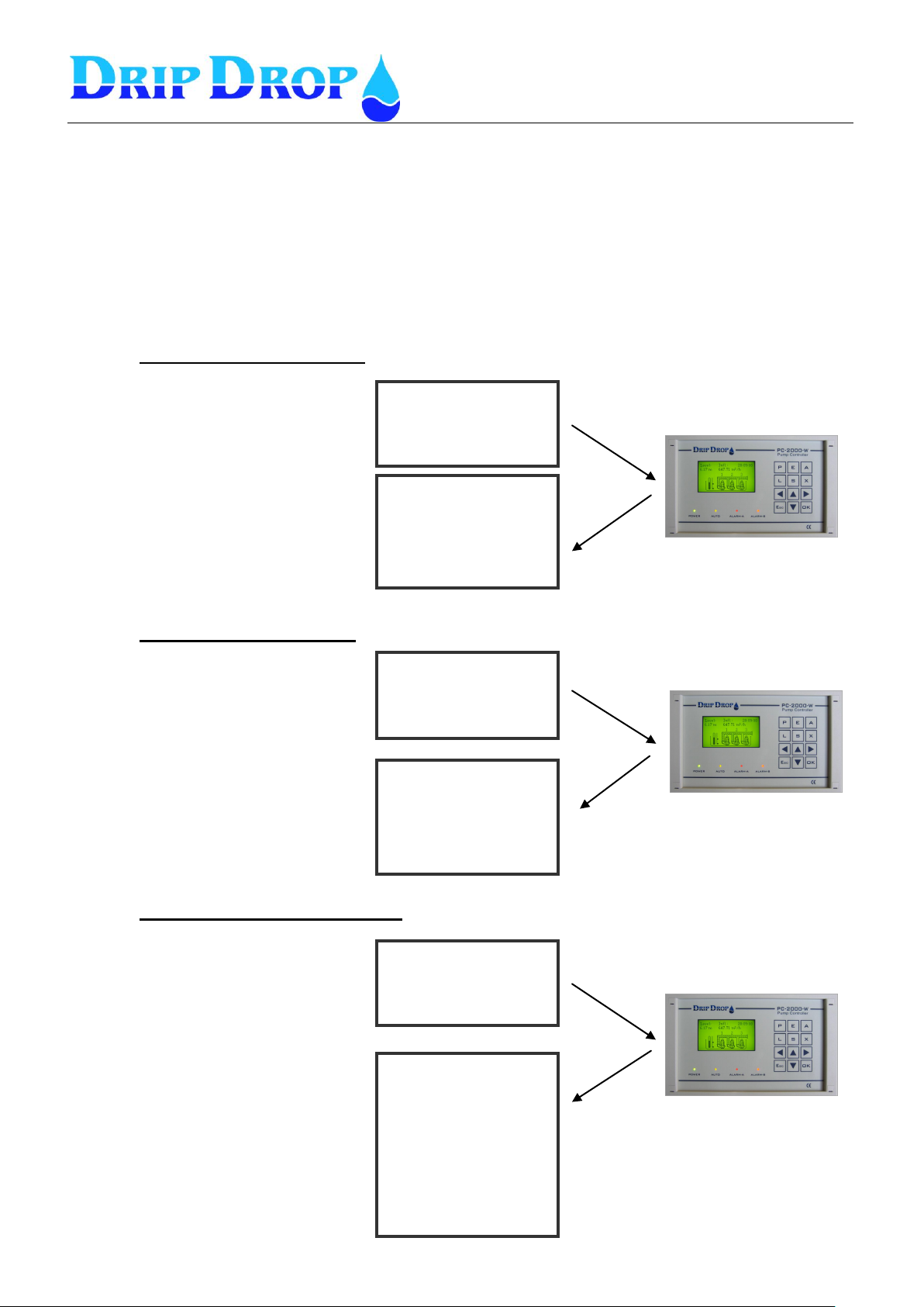
MANUAL PC-2000-W
Ver. 30.56.12-UK/101208
Page 53 (71)
Get a
Alarms occured:
1. Alarm pump 1
Over current
2. Alarm pump 2
NOT in AUTO
To receive information about
active alarms –
Send following message
Received message is an answer
with a list of active alarms…
Get s
Pump status:
P1 No of starts: 10
P1 Operation time: 5.25
P2 o of tarts: 9
P2 Operation time: 5.10
To receive information about the
pump status-Send following message
Received message of the status of
the pumps, how many starts of the
pumps and operation time today.
Get d
Valores actuales:
Level (m):
Q in (l/s):
Q out (l/s):
Qoverflow(l/s)
B1 = OFF
B2 = ON
B3 = OFF
B4 = OFF
To receive information about the
actual values –
Send following message
Received message with actual
level, in and outflow and overflow
and if pumps are running or not.
6.3 Sending inquiries to the station by mobile phone.
In addition to receive SMS alarms from the controller, you can send inquiries for information to the
unit. The information that you can ask for is divided into three different pre-established information
groups:
1. Information for active alarms
2. Operation hours and number of starts today (from midnight)
3. Information on actual values in the station, level, in/outflow and on/off status of pumps.
1. Information group (Alarms)
2. Information group (Status)
3. Information group (Station data)
Page 54
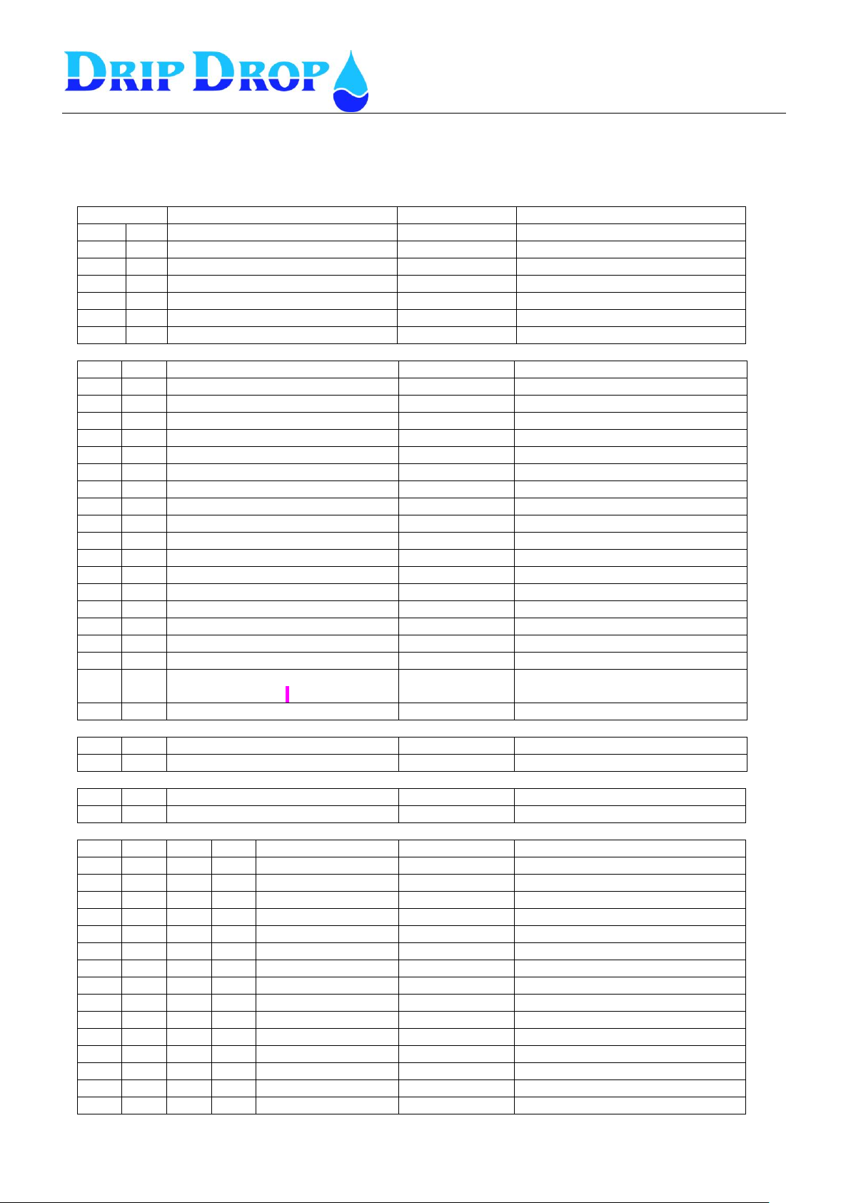
MANUAL PC-2000-W
Ver. 30.56.12-UK/101208
Page 54 (71)
I/O No.
Signal type
Signal function
Notes
AI
1
Level signal
4-20 mA
AI
2
Flow signal
4-20 mA
AI
3
P1 Motor current / Running confirm.
4-20 mA
AI
4
P2 Motor current / Running confirm.
4-20 mA
AI
5
P3 Motor current / Running confirm.
4-20 mA
AI
6
P4 Motor current / Running confirm.
4-20 mA
AI
7
Attendance alarm/ Intruder alarm
4-20 mA
Works like DI, with resistor.
DI 1 Low level switch
NO
mostly NC
DI 2 High level switch
NO
DI 3 Overflow switch
NO
DI 4 P1 Not in auto (H-0-A)
NO
mostly NC
DI 5 P1 Motor protection
NO
DI 6 P1 Thermo protection
NO
mostly NC
DI 7 Internal alarm 1 / Extern block. P1
NO
DI 8 P2 Not in auto (H-0-A)
NO
mostly NC
DI 9 P2 Motor protection
NO
DI
10
P2 Thermo protection
NO
mostly NC
DI
11
Internal alarm 2 / Extern block. P2
NO
DI
12
P3 Not in auto (H-0-A)
NO
mostly NC
DI
13
P3 Motor protection
NO
DI
14
P3 Thermo protection
NO
mostly NC
DI
15
Internal alarm 3 / Extern block. P3
NO
DI
16
P4 Not in auto (H-0-A)
NO
mostly NC
DI
17
P4 Motor protection
NO
DI
18
P4 Thermo protection
NO
mostly NC
DI
19
Internal alarm 4 / Extern block. P4
Alarm confirmation.
NO
DI
20
Block all pumps / Phase failure
NO
CI 1 Flow meter / Rain meter (Pulses)
--
CI 2 Energy meter / Flow meter (Pulses)
--
AO
1
Analoge Out (4-20 mA)
4-20 mA
Mirror of AI 1-7
AO
2
Analoge Out (0-10 V)
0-10V
Mirror of AI 1-7
DO 1 ND1
C1
P1 Start/Stop
NO
DO 2 ND2
C2
P1 Reset Motor Prot.
NO
DO 3 ND3
C3
P2 Start/Stop
NO
DO 4 ND4
C4
P2 Reset Motor Prot.
NO
DO 5 ND5
C5
P3 Start/Stop
NO
DO 6 ND6
C6
P3 Reset Motor Prot.
NO
DO 7 ND7
C7
P4 Start/Stop
NO
DO 8 ND8
C8
P4 Reset Motor Prot.
NO
DO 9 ND9
C9
Mixing/Flushing 1
NO
DO
10
ND10
C10
Mixing/Flushing 2
NO
DO
11
ND11
C11
Attendance alarm
NO
For alarm horn – Alarm is sent.
DO
12
ND12
C12
Alarm (not ackn.)
NC
DO
13
ND13
C13
Alarm (Active)
NC
DO
14
ND14
C14
Not used
NO
DO
15
ND15
C15
Not used
NO
DO
16
ND16
C16
Modem reset
NC
Interrupts power to GSM-modem.
7 I/O-list, Signal table
Page 55
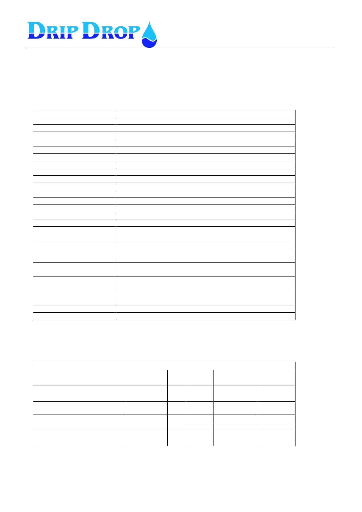
MANUAL PC-2000-W
Ver. 30.56.12-UK/101208
Page 55 (71)
Powersuply
24 VDC ( 19,2 -30 VDC)
Power consumption
0.15 A
Mounting cut out
Panelmounted (203.5 mm x 115 5 mm)
Outer dimensions
213 x 125 x54 mm ( B x H x Dj)
Temperature range
-5 to +55 °C
Housing
IP 54 ( IP 65 from front)
Weight
0,6 kg
Processor
AMTEL ATMAGA 128
Memory
SRAM, E2PROM,FEPROM
Graphic display
128 x 64 dots
Operator keys
12
LED´s
1 green, 1 yellow, 2 red.
Internal battery (Litium)
CdLi, for real tim clock and settings
Signal connections
Band cable 1x26, 1x 20,1x14
Digital outputs
16DO, 24 VDC open colector
Max. load 50 mA at 30 VDC
Digital inputs
20DI, 24 VDC Optoisolated max. 500 V (1 min)
Counter inputs
2, 24 VDC Optoisolated max. 500 V (1 min)
Max frequency 500 Hz
Analogue inputs
7 AI 0/4-20 mA at 24 VDC
Max impedance 100 ohm
Analogue current output
1 AO, 4-20 mA at 24 VDC
Max load 500 ohm
Analogue voltage output
1 AO, 0-10 V
Min Load 1000 ohm
Communication port 1
1 , RS232, 57600 BAUD
Communckation port 2
1 ,RS485, 57600 BAUD
Electromagnetic compatibility (EMC)
Description
Standard
Class
Level
Remarks
Test
Network frequencymagnetioc fields
CEI 61000-4-8
30A/m A
Immunity to radiated RF - fields
CEI 61000-4-3
3
10V/m
26MHz-1GHz
A
Electostatic discharge immunity
CEI 61000-4-2
4
8kV
Air discharge
C
4kV
Cont. discharge
C
Radiated emission
EN 52022:2004
A 26MHz-1GHz
A
8 Tecnical information
8.1 Specification PC-2000-W
8.2 Electromagnetic compatibility (EMC)
Page 56
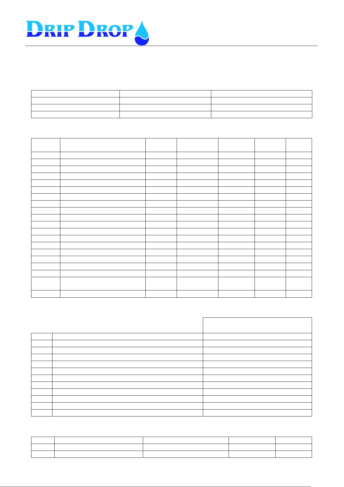
MANUAL PC-2000-W
Ver. 30.56.12-UK/101208
Page 56 (71)
Application type
No. Of pumps
Max No of working pumps
Start float
Stop way:
No
Type
Function
Signal type
Alarm type
Block
Delay
[s]
DI1
Low level switch
In use
NC
B-alarm
1 DI 2
High level switch
In use
NO
A-alarm
1 DI 3
Overflow switch
In use
NO
A-alarm
1 DI 4
P1 Not in Auto(H-0-A)
In use
NC
B-alarm
1 DI 5
P1 Motor protection
In use
NO
A-alarm
1 DI 6
P1 Thermo protection
In use
NC
A-alarm
no 1 DI 7
Int./Ext. alarm 1/ Ext.block.P1
Not used
NO
A-alarm
no 1 DI 8
P2 Not in Auto(H-0-A)
In use
NC
B-alarm
1 DI 9
P2 Motor protection
In use
NO
A-alarm
1 DI 10
P2 Thermo protection
In use
NC
A-alarm
no
1
DI 11
Int./Ext. alarm 2/ Ext.block.P2
Not used
NO
A-alarm
no
1
DI 12
P3 Not in Auto (H-0-A)
DI 13
P3 Motor protection
DI 14
P3 Thermo protection
DI 15
Int./Ext. alarm 3/ Ext.block.P3
Not used
NO
A-alarm
no
1
DI 16
P4 Not in Auto (H-0-A)
DI 17
P4 Motor protection
DI 18
P4 Thermo protection
DI 19
Int./Ext. alarm 4/ Ext.block.P4
Gral. Alarm confirmation
Not used
NO
A-alarm
no
1
DI 20
Block all pumps/ Phase failure
Not used
NO
A-alarm
Not used
Signal
DO2
P1 Reset M. Protection
DO4
P2 Reset M. Protection
DO6
P3 Reset M. Protection
DO8
P4 Reset M. Protection
DO9
Mixer 1 Start / Stop
DO10
Mixer 2 Start / Stop
DO11
Horn Inter. / Pers, Alarm
DO12
Alarm Not Ack.
DO13
Alarm (Active)
DO14
Not in Use
DO15
Not in Use
DO16
Modem reset
Function
1 Puls
Max delay
CI1
Counter 1
Rainmeter (Water flow)
1 mm
1
CI2
Counter 2
Power meter (Water flow)
1 kWh
1
9 Configuration table
Digital inputs
Digital outputs
Counters
Page 57
MANUAL PC-2000-W
Ver. 30.56.12-UK/101208
Page 57 (71)
Signal
Range
0/4 mA
Range
20 mA
AI1
Level sensor
4-20 mA
0,00 m
10 m
AI2
Flow meter
AI3
P1 Motor current
4-20 mA
0,0 A
250.0 A
AI4
P2 Motor current
4-20 mA
0,0 A
250.0 A
AI5
P3 Motor current
AI6
P4 Motor current
AI7
Intruder/ pers. alarm
Mirror
Range
AO1
Analogue output 1
AI1
AO2
Analogue output 2
AI1
Pump 1
Pump 2
Pump 3
Pump 4
Daytime levels
Start[m]:
1.00 m
Stopp[m]:
0.50 m
Nighttime levels
Start:
Stopp[m]:
Alternation :
Yes / No
Back-up starr:
Yes / Noj
Max.runtime:
[min]:
240
Min. breaktime:
[sek]:
10
Check after:
[h]
Check for:
[s]
Service time:
Service after [h]:
Alarm type:
Reload time:
Random starts.
[cm]:
10
Running confirmation
Function
In use
Confirm. time [s]
5
Block pump
No
Alarm type
A-Alarm
Current settings
Block pump
Yes
Pump start time [s]
10
Low current
I-min[A]
100.0
Delay on [s]
5
Alarm type
A-alarm
High current
I-max[A]
200.o
Delay on[s]
5
Alarm type
A-alarm
Pump Capacity
Nom.cap.[l/s]
0
Min. cap.[l/s]
0
Alarmtype
Not act.
Reset protection
No of retries
Pause time [s]
Reset time[s]
Analogue inputs
Analogue outputs
Setting of pumps
Page 58
MANUAL PC-2000-W
Ver. 30.56.12-UK/101208
Page 58 (71)
Alternation
Type:
Alt.at failurel:
Time / delays
Start delay: [s]:
Stop delay:[s]
Min.- time starts [s]:
Min.- time stops [s] :
Switching time [s]:
Back-up time [min]:
Daytime [h.m]:
Nighttime [h.m.]:
Level alarm
High level
Level[m] :
Alarm delay [s]:
Alarm type:
Low level
Level[m] :
Alarm delay [s]:
Alarm type:
Overflow level
Level[m] :
Alarm delay [s]:
Alarm type
Idle Alarm
Measuring window%
Alarm delay[h]
Alarm type
Cleaning sequencies
Pit cleaning
Pit clean starts:
Alt. Stop level[m]:
Alt. stopdelay [s]:
Pipe cleaning
Pipe clean starts:
Alternative start.[m]:
Flush number:
Mixer 1
Level functionality
Type:
Startcycles:
Startlevel[m]:
Startdelay[s]:
Runtime[s]:
Timer functionality
Type:
Starta after[h]:
Runtime[s]:
Block if pump ON:
Mixer 2
Level functionality
Type:
Startcycles:
Startlevel[m]:
Startdelay[s]:
Runtime[s]:
Timer functionality
Type:
Starta after[h]:
Runtime[s]:
Block if pump ON:
Station settings
Page 59
MANUAL PC-2000-W
Ver. 30.56.12-UK/101208
Page 59 (71)
Inflow calculation
Inflow calc.time. [s]:
Cap. Calc. Time [s]:
Start delay [s]::
Stop delay [s]::
Inflow level. [m]:
2 pumps comp.[%]
2 pumps comp.[%]
2 pumps comp.[%]
Pit desciption
Level 0 [m]
Area 0[m]
Level 1[m]
Area 1 [m2]
Level 2 [m]
Area 2 [m2]
Level 3 [m]
Area 3 [m2]
Level 4 [m]
Area 4 [m2]
Level 5 [m]
Area 5 [m2]
Level 6 [m]
Area 6 [m2]
Level 7 [m]
Area 7 [m2]
Level 8 [m]
Area 8 [m2]
Spec.cons.:
Station settings- cont.
Page 60
MANUAL PC-2000-W
Ver. 30.56.12-UK/101208
Page 60 (71)
Op. access code:
▲▲▲▲
Syst, access code
▼▼▼▼
Level bargraph
0% [m]: 0.00
100% [m]: 5.00
Logger settings
Sample interval:
5 min
Logger type:
Stack, Ring or Fixed
Settings RS 232
Comm.settings
Baud rate:
Parity:
Stop bits:
Protocol:
Device address:
Station ID:
Connection.
Link:
GSM (Direct, dial up)
Reset modem [min]:
0
Pulse duration[s]:
0
Hayes:
PIN kod:
N1:
N2:
N3:
Stn:(Station name):
Remote acknowledge:yes/ no
no
Ack. timeout[x10s]:
12
*Idc: (Station name)
*Answer after:
2
*Alarm resend No:
*Retry time[s]:
0
*Call on alarm OFF: no
Settings RS485
Comm settings
Acts as:
nothing
Baud rate
1200
Parityt:
none
Stop bits:
1
Protocol:
COMLI
Time out[s]:
Ext.units type
485
Type:
Address:
Name:
Reset/ Erase
Logged data
Alarm
Reset floats
Counters
Volume/Energy
Pump 1,2,3,4
Miscellaneous
Page 61
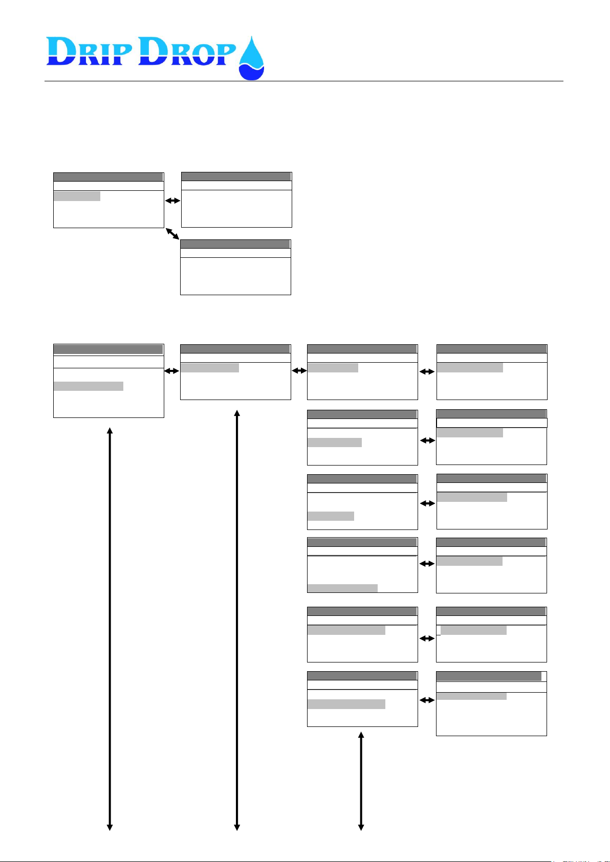
MANUAL PC-2000-W
Ver. 30.56.12-UK/101208
Page 61 (71)
Settings ( ) v30.56.XX
-Number of pumps: 4
-Max. running pumps: 2
-Start float: No
Application
Settings ( ) v30.56.XX
▪Application
▪I/O configuration
▪Pump settings
▪Station settings
..
Settings( ) v30.56.XX
▪Digital inputs
▪Digital outputs
▪Counters
▪Analogue inputs
I/O Configuration
Settings( ) v30.56.XX
-Function: in use
Function: in use
-Signal type: NC
-Alarm type: B-Alarm
-Delay on /off[s]: 1
01.Low float
Settings ( ) v30.56.XX
▪01.Low float
▪02.High float
▪03.Overflow
▪04.P1 Not in Auto
Digital inputs
Settings( ) v30.56.XX
Inställningar ( ) v30.56.XX
▪01.Low float
▪02.High float
▪03.Overflow
▪04.P1 Not in Auto
Digital inputs
Settings( ) v30.56.XX
Inställningar ( ) v30.56.XX
▪05.P1 Motor protect
▪06.P1 Temp. Protec .
▪07. Int/Ext.alarm 1
▪08.P2 Not in Auto
Digital inputs
Settings( ) v30.56.XX
Inställningar ( ) v30.56.XX
Function: in use
-Signal type NO
-Alarm type: A-Alarm
- Delay on /off[s]: 1
02.High float
Settings( ) v30.56.XX
Inställningar ( ) v30.56.XX
▪01.Low float
▪02.High float
▪03.Overflow
▪04.P1 Not in Auto
Digital inputs
Settings( ) v30.56.XX
Inställningar ( ) v30.56.XX
-Function: in use
-Signal type: NO
-Alarm type: B-Alarm
- Delay on /off[s]: 1
03.Overflow
Settings( ) v30.56.XX
Inställningar ( ) v30.56.XX
▪01.Low float
▪02.High float
▪03.Overflow
▪04.P1 Not in Auto
Digital inputs
Settings( ) v30.56.XX
Inställningar ( ) v30.56.XX
-Function: i use
-Signal type: NC
-Alarm type: B-Alarm
- Delay on /off[s]: 1
04.P1 Not in Auto
Settings( ) v30.56.XX
Inställningar ( ) v30.56.XX
-Function: in use
-Signal type NO
-Alarm type: B-Alarm
- Delay on /off[s]: 1
05.P1 Motor protect
Settings( ) v30.56.XX
Inställningar ( ) v30.56.XX
▪05.P1 Motor protect
▪06.P1 Temp. protect
▪07.Int/Ext.alarm 1
▪08.P2 Not in Auto
Digital inputs
Settings ( ) v30.56.XX
-Function: in use
-Signal type: NC
-Alarm type: B-Alarm
-Block Pump: No
- Delay on /off[s]: 1
06.P1 Temp. protect
Settings( ) v30.56.XX
▪
Application type
▪I/O configuration
▪Pump settings
▪Station settings
▪Miscellaneous
..
Settings ( ) v30.56.XX
-Number of pumps: 4
-Max. running pumps: 2
-Start float: Yes
-Stop way: sequencial
Application
If the start floats option is set to YES, an additional
setting line will appear to choose how to stop the
pumps with the levelswitches.
- sequencial
- general stop
- own stop
More info see 5.2.
10 Menu structure – System settings
Application
I/O Settings - Digital inputs
Page 62
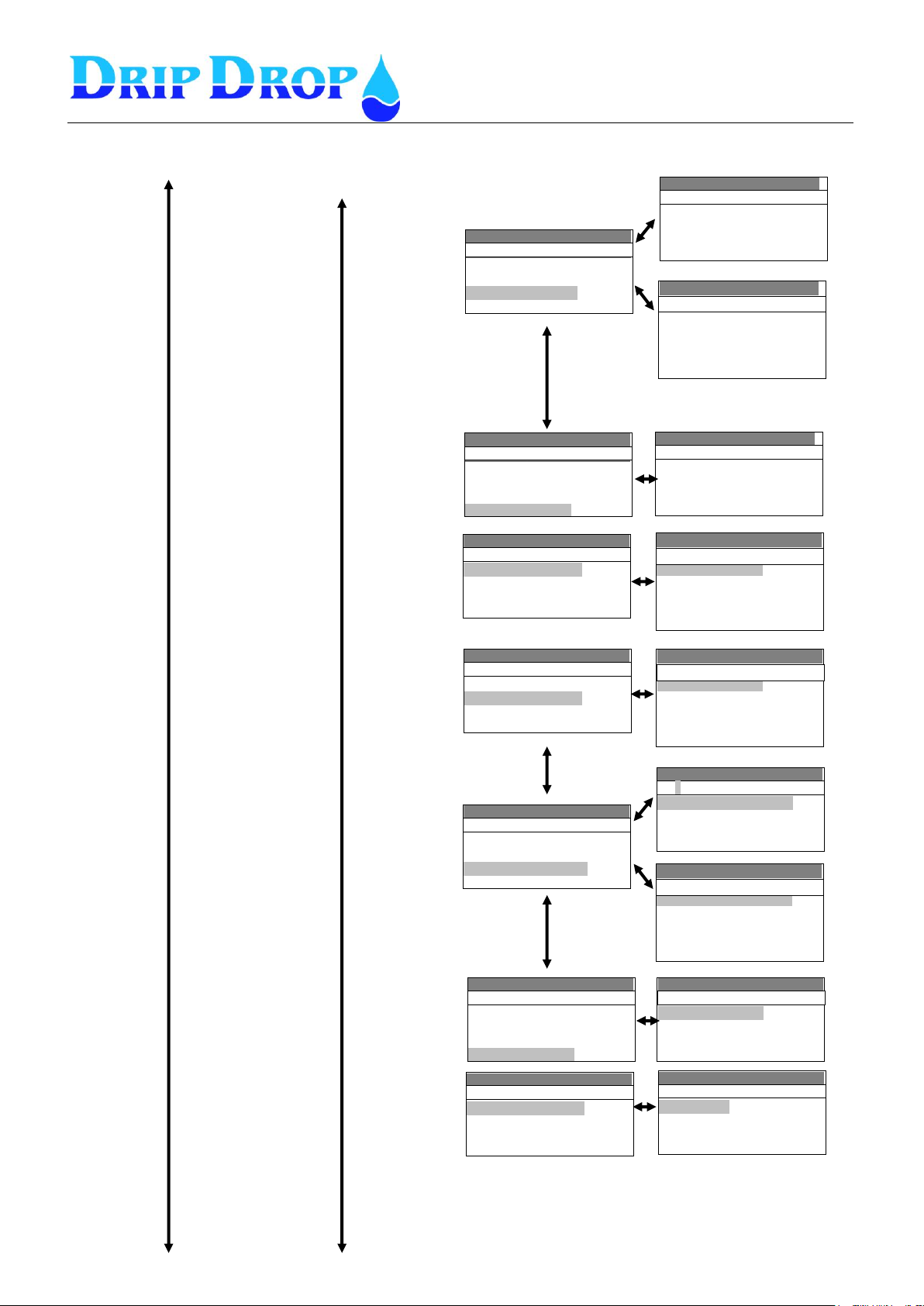
MANUAL PC-2000-W
Ver. 30.56.12-UK/101208
Page 62 (71)
Settings ( ) v30.56.XX
-Function: Ext. alarm P1
-Signal type: NO
-Alarm type: A-larm
-Delay on /off[s]: no
07. Int/Ext.alarm 1
Settings ( ) v30.56.XX
-Function: in use
-Signal type: NC
-Alarm type: B-Alarm
- Delay on /off[s]: 1
08.P2 Not in Auto
Settings( ) v30.56.XX
Inställningar ( ) v30.56.XX
▪05.P1 Motor protect
▪06.P1 Temp. protect
▪07.Int/Ext.alarm 1
▪08.P2 Not in Auto
Digital inputs
Settings( ) v30.56.XX
Inställningar ( ) v30.56.XX
▪05.P1 Motor protect
▪06.P1 Temp. protect
▪07.Int/Ext.alarm 1
▪08.P2 Not in Auto
Digital inputs
Settings ( ) v30.56.XX
-Funcion: Int. Alarm P1
-Signal type: NO
-Alarm type: A-Alarm
-Block Pump: No
-Delay on /off[s]:1
07.External Alarm 1
Settings( ) v30.56.XX
-Function: in use
-Signal type: NC
-Alarm type: B-alarm
-Block Pump: No
- Delay on /off[s]:
10.P2 Temp. protect
Settings( ) v30.56.XX
▪09.P2 Motor Protect
▪10.P2 Temp. Protect
▪11.Int/ Ext. Alarm 2
▪12.P3 Not in Auto
Digital inputs
Settings( ) v30.56.XX
▪09.P2 Motor Protect
▪10.P2 Temp. Protect
▪11.Int/ Ext. Alarm 2
▪12.P3 Not in Auto
Digital inputs
Settings( ) v30.56.XX
-Function: Ext. Alarm 2
-Signal type: NO
-Alarm type: B-Alarm
- Delay on /off[s]:
11. Int/ Ext. Alarm 2
Settings( ) v30.56.XX
-Function: Int alarm P2
-Signal type: NO
-Alarm type: B-Alarm
-Block Pump: No
- Delay on /off[s]:
11.External Alarm 2
Settings( ) v30.56.XX
▪13.P3 Motor Protect
▪14.P3 Temp. Protect
▪15.Int/ Ext. Alarm 3
▪16.P4 Not in Auto
Digital inputs
Settings( ) v30.56.XX
▪09.P2 Motor Protect
▪10.P2 Temp. Protect
▪11.Int/ Ext. Alarm 2
▪12.P3 Not in Auto
Digital inputs
Settings( ) v30.56.XX
-Function: in use
-Signal type: NC
-Alarm type: B-alarm
- Delay on /off[s]: 1
09.P2 Motor protect
Settings( ) v30.56.XX
▪09.P2 Motor Protect
▪10.P2 Temp. Protect
▪11.Int/ Ext. Alarm 2
▪12.P3 Not in Auto
Digital inputs
Settings( ) v30.56.XX
-Function: in use
-Signal type: NC
-Alarm type: B-Alarm
- Delay on /off[s]:
13.P3 Not in Auto
Settings( ) v30.56.XX
-Function: in use
-Signal type: NO
-Alarm type: B-Alarm
- Delay on /off[s]:
13.P3 Not in Aut
I/O Settings cont.
Digital inputs cont.
Page 63
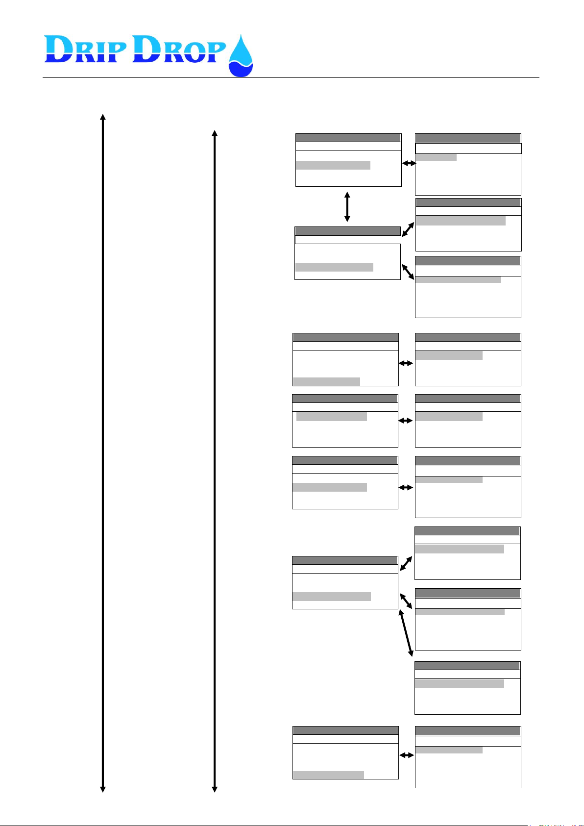
MANUAL PC-2000-W
Ver. 30.56.12-UK/101208
Page 63 (71)
Settings( ) v30.56.XX
▪13.P3 Motor Protect
▪14.P3 Temp. Protect
▪15.P3 Int/Ext.alarm
▪16.P4 Not in Auto
Digital inputs
Settings( ) v30.56.XX
-Function: Ext. alarm 3
-Signal type: NO
-Alarm type: B-Alarm
- Delay on /off[s]:
15.External alarm 3
Settings( ) v30.56.XX
▪13.P3 Motor Protect
▪14.P3 Temp. Protect
▪15.Int/ Ext. Alarm 3
▪16.P4 Not in Auto
Digital inputs
Settings( ) v30.56.XX
-Function: ext. alarm 4
-Signal type: NO
-Alarm type: B-Alarm
- Delay on /off[s]:
19.External alarm 4
Settings( ) v30.56.XX
-Function: in use
-Signal type: NC
-Alarm type: B-Alarm
-Block Pump: No
- Delay on /off[s]:
20.Block all Pumps
Settings( ) v30.56.XX
▪17.P4 Motor Protect
▪18.P1 Temp. Protect
▪19. Int/Ext.alarm 4
▪20.Block all Pumps
Digital inputs
Settings( ) v30.56.XX
▪17.P1 Motor Protect
▪18.P1 Temp. Protect
▪19. Int/Ext.alarm 4
▪20.Block all Pumps
Digital inputs
Settings( ) v30.56.XX
-Function: Int alarm P4
-Signal type: NO
-Alarm type: B-alarm
-Block Pump: No
- Delay on /off[s]:
19.External alarm 4
Settings( ) v30.56.XX
▪17.P4 Motor Protect
▪18.P4 Temp. Protect
▪19. Int/Ext.alarm 4
▪20.Block all Pumps
Digital inputs
Settings( ) v30.56.XX
-Function: in use
-Signal type: NO
-Alarm type: B-Alarm
- Delay on /off[s]:
17.P4 Motor prot.
Settings( ) v30.56.XX
▪17.P4 Motor Protect
▪18.P4 Temp. Protect
▪19. Int/Ext.alarm 4
▪20.Block all Pumps
Digital inputs
Settings( ) v30.56.XX
-Function: in use
-Signal type: NC
-Alarm type: B-Alarm
-Block Pump: No
- Delay on /off[s]:
18.P4 Temp. prot
Settings( ) v30.56.XX
-Function: in use
-Signal type: NC
-Alarm type: B-Alarm
- Delay on /off[s]:
16.P4 Not in auto
Settings( ) v30.56.XX
▪13.P3 Motor Protect
▪14.P3 Temp. Protect
▪15. Int/Ext.alarm 3
▪16.P4 Not in Auto
Digital inputs
Settings( ) v30.56.XX
-Function: Int alarm P3
-Signaltype: NO
-Alarm type: B-Alarm
-Block Pump: No
-Delay on /off[s]:
15.External alarm 3
Settings( ) v30.56.XX
-Function: in use
-Signaltype: NC
-Alarm type: B-Alarm
-Block Pump: No
-Delay on /off[s]:
14.P3 Temp. Protect.
Settings( ) v30.56.XX
-Function: Alarm confirm
-Signal type: NO
19.External alarm 4
I/O Settings cont.
Digital inputs cont.
Page 64
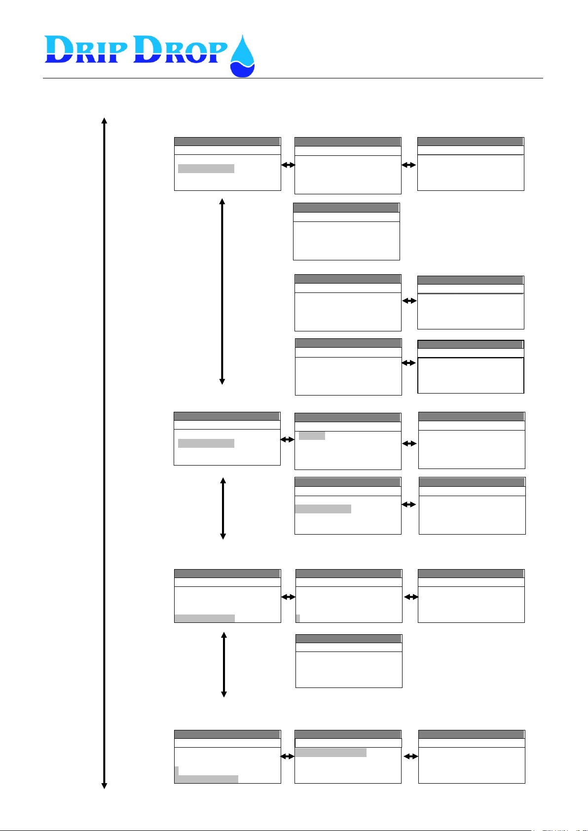
MANUAL PC-2000-W
Ver. 30.56.12-UK/101208
Page 64 (71)
Settings( ) v30.56.XX
Inställningar ( ) v30.56.XX
▪01.P1 Start/Stop
▪02.P1 Multipurpose Out
▪03.P2 Start/Stop
▪04.P2 Multipurpose Out
Digital outputs
Settings( ) v30.56.XX
Inställningar ( ) v30.56.XX
-Signal type: NO
-Function: remote control
-Pulse time[s] 10
02.P1 Multipurpose Out
Settings( ) v30.56.XX
Inställningar ( ) v30.56.XX
▪05.P3 Start/Stop
▪06.P3 Multipurpose Out.
▪07.P4 Start/Stopf
▪08.P4 Multipurpose Out.
Digital outputs
Settings( ) v30.56.XX
Inställningar ( ) v30.56.XX
▪09.Mix1 Start /Stop
▪10.Mix2 Start/Stopp
▪11.Horn Intr./Pers.alarm
▪12.Alarms Not ACK.
Digital outputs
Settings( ) v30.56.XX
Inställningar ( ) v30.56.XX
▪13.Alarm Active
▪14.Multipurpose Out
▪15.AI2 Alarm output
▪16.Reset Modem
Digital outputs
Settings( ) v30.56.XX
Inställningar ( ) v30.56.XX
▪01.Flowmeter/Rain meter-CI1
▪02.Energymeter -CI2
Digital counters
Settings( ) v30.56.XX
Inställningar ( ) v30.56.XX
-Function: flowmeter
-Pulse unit:m3/h
-1 Pulse [m3]: 1
-Max delay [s]: 1
Flowmeter -CI1
Settings( ) v30.56.XX
Inställningar ( ) v30.56.XX
▪01.Flowmeter/Rainmeter -CI1
▪02.Energimeter/Flowm. -CI2
Digital counters
Settings( ) v30.56.XX
Inställningar ( ) v30.56.XX
-Function: energymeter
-Pulse unit:kWh
-1 Pulse [kW]: 1
-Max delay [s]: 1
Flowmeter -CI1
Settings( ) v30.56.XX
▪Digital inputs
▪Digital outputs
▪Counters
▪Analogue inputs
I/O Configuration
Settings( ) v30.56.XX
▪Digital inputs
▪Digital outputs
▪Counters
▪Analogue inputs
I/O Configuration
Settings( ) v30.56.XX
▪Digital inputs
▪Digital outputs
▪Counters
▪Analogue inputs
I/O Configuration
Settings( ) v30.56.XX
▪Level sensor -AI1
▪Flowmeter -AI2
▪Pump current P1
▪Pump current P2
Analogue inputs
Settings( ) v30.56.XX
▪Pump current P3
▪Pump current P4
▪Intruder alarm
Analogue inputs
Settings( ) v30.56.XX
-Type: 4/20 mA
-0/4 mA [m]: 0.00
-20 mA [m]: 10.00
Level sensor -AI1
Settings( ) v30.56.XX
▪Digital outputs
▪Counters
▪Analogue inputs
▪Analogue outputs
I/O Configuration
Settings( ) v30.56.XX
▪Analogue outputs 1
▪Analogue output 2
Analogue outputs
Settings( ) v30.56.XX
-Mirror: AI 1
- 4 mA: 0.00
- 20 mA: 0.00
Analogue output
Settings( ) v30.56.XX
Inställningar ( ) v30.56.XX
-Signal type: NO
-Function: remote control
-Pulse time[s] 10
02.P1 Multipurpose Out
02.P1 Multipurpose Out
Settings( ) v30.56.XX
Inställningar ( ) v30.56.XX
-Signal type: NO
02.Mix 1 start/Stop
I/O Settings cont.
Digital outputs
Digital counters
Analogue inputs
Analogue outputs
Page 65
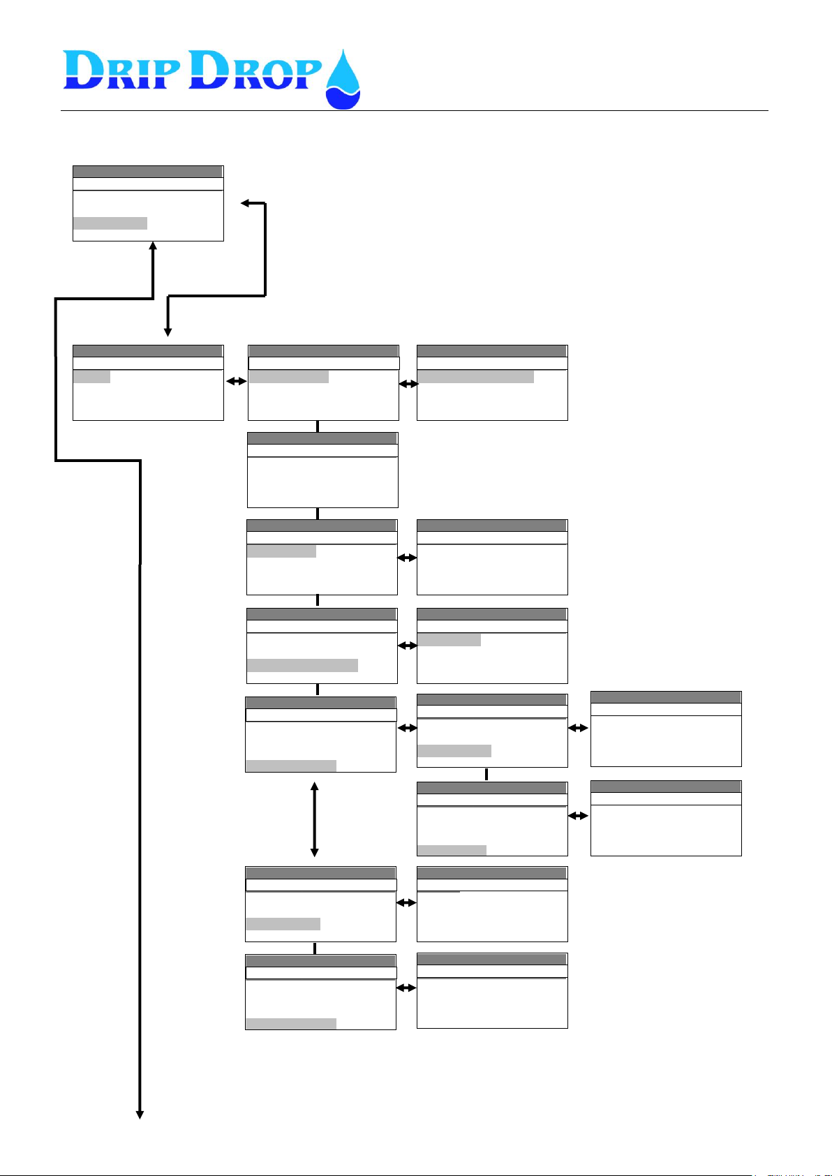
MANUAL PC-2000-W
Ver. 30.56.12-UK/101208
Page 65 (71)
Settings( ) v30.56.XX
Inställningar ( ) v30.56.XX
▪Pump 1
▪Pump 2
▪Pump 3
▪Pump 4
Pump settings
Settings( ) v30.56.XX
Inställningar ( ) v30.56.XX
-Max. Runtime [min]: 240
-Min. Breaktime[s]: 10
-Check after [h]: 0
-Check for [s]: 0
Pump 1
Settings( ) v30.56.XX
Inställningar ( ) v30.56.XX
▪Daytime levels
▪Nighttime levels
-Alternation: yes
-Back-up start: No
Pump 1
Settings( ) v30.56.XX
Inställningar ( ) v30.56.XX
-Start level [m]: 2.25
-Stop level [m]: 0.45
Daytime
Settings( ) v30.56.XX
Inställningar ( ) v30.56.XX
▪Service time
-Random starts[cm]: 10
▪Running confirmation
▪Current settings
Pump 1
Settings( ) v30.56.XX
Inställningar ( ) v30.56.XX
▪Running confirmation
▪Current settings
▪Pump capacity
▪Reset protection
Pump 1
Settings( ) v30.56.XX
Inställningar ( ) v30.56.XX
-Service after[h]: 6000
-Alarm type: B-Alarm
▪Reload time
Service time
Settings( ) v30.56.XX
Inställningar ( ) v30.56.XX
▪Service time
-Random starts[cm]: 0
▪Running confirmation
▪Current settings
Pump 1
Settings( ) v30.56.XX
Inställningar ( ) v30.56.XX
-Function: in use
-Confirm time[s]: 5
-Blocks Pumps: No
-Alarm typ: A-Alarm
Running confirmation
Settings( ) v30.56.XX
Inställningar ( ) v30.56.XX
▪Service time
-Random starts[cm]: 0
▪Running confirmation
▪Current settings
Pump 1
Settings( ) v30.56.XX
Inställningar ( ) v30.56.XX
-Block pump: No
-Pumpstart time[s]: 5
▪Under current
▪Over current
Current settings
Settings( ) v30.56.XX
20.54.42
-Nom. capacity.[l/s]: 0.0
-Min. capacity.[l/s]: 0.0
-Alarm type: non active
Pump capacity
Settings( ) v30.56.XX
Inställningar ( ) v30.56.XX
▪Running confirmation
▪Current settings
▪Pump capacity
▪Reset protection
Pump 1
Settings( ) v30.56.XX
Inställningar ( ) v30.56.XX
-No of retries: 0
-Pause time[s]: 0
-reset time[s]: 0
Reset protection
Settings( ) v30.56.XX
Inställningar ( ) v30.56.XX
-Block Pump: Yes
-Pump start time[s]: 5
▪Under current
▪Over current
Current settings
Settings( ) v30.56.XX
-I-max[A]: 20.5
-Delay on[s]: 5
-Alarm type: A-alarm
Over current
Settings( ) v30.56.XX
Inställningar ( ) v30.56.XX
▪Application type
▪I/O configuration
▪Pump settings
▪Station settings
..
Settings( ) v30.56.XX
-I-min[A]: 20.5
-Delay on[s]: 5
-Alarm type: A-alarm
Under current
Pumpsettings
Page 66
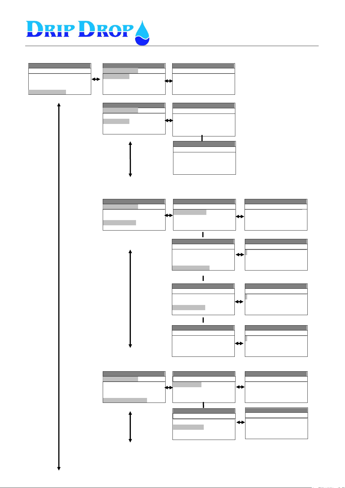
MANUAL PC-2000-W
Ver. 30.56.12-UK/101208
Page 66 (71)
Settings( ) v30.56.XX
Inställningar ( ) v30.56.XX
▪Alternation
▪Time/delays
▪Station alarms
▪Cleaning sequencies
Station settings
Settings( ) v30.56.XX
Inställningar ( ) v30.56.XX
▪Alternation
▪Time/delays
▪Station alarms▪Cleaning
sequencies
Station settings
Settings( ) v30.56.XX
vInställningar ( ) 4.42
-Start delay[s]: 1
-Stop delay[s]: 1
-Mintime starts[s]: 15
-Mintime stops[s]: 15
Time/delays
Settings( ) v30.56.XX
Inställningar ( ) v30.56.XX
-Typ: Cyclic
-on failure: Yes
Alternation
Settings( ) v30.56.XX
Inställningar ( ) v30.56.XX
-Switching time[s]: 5
-Back-up time[min]: 1
-Daytime[h.m]: 00.00
-Nighttime[h.m]: 00.00
Time/delays
Settings( ) v30.56.XX
Inställningar ( ) v30.56.XX
▪Alternation
▪Time/delays
▪Station alarms
▪Cleaning sequencies
Station settings
Settings( ) v30.56.XX
Inställningar ( ) v30.56.XX
▪Overflow level
▪High level
▪Low level
▪Level lock guard
Startion alarms
Settings( ) v30.56.XX
vvInställningar ( ) 54.42
-Level[m]: 3.00
-Alarm delay[s]: 1
-Alarm type: A-larm
High level
Settings( ) v30.56.XX
Inställningar ( ) v30.56.XX
▪Alternation
▪Time/delays
▪Level alarms
▪Cleaning sequencies
Station settings
Settings( ) v30.56.XX
Inställningar ( ) v30.56.XX
▪Pit cleaning
▪Pipe cleaning
Cleaning sequencies
Settings( ) v30.56.XX
Inställningar ( ) v30.56.XX
-Pit clean starts: 0
-Alternative stop[m]: 0.00
-Alt. stop delay[s]: 0
Pit cleaning
Settings( ) v30.56.XX
Inställningar ( ) v30.56.XX
▪Pit cleaning
▪Pipe cleaning
Cleaning sequencies
Settings( ) v30.56.XX
Inställningar ( ) v30.56.XX
-pipe clean starts: 0
-Altenative start [m]: 0.00
-Flush number: 0
Pipecleaning
Settings( ) v30.56.XX
Inställningar ( ) v30.56.XX
▪Application type
▪I/O configuration
▪Pump settings
▪Station settings
..
Settings( ) v30.56.XX
Inställningar ( ) v30.56.XX
▪Overflow level
▪High level
▪Low level
▪Level lock guard
Station alarms
Settings( ) v30.56.XX
Inställningar ( ) v30.56.XX
▪ Measurimg window[%]
▪ Alarm delay [h]
▪ Alarm type
Level lock guard
Settings( ) v30.56.XX
Inställningar ( ) v30.56.XX
▪Low level
▪Level lock guard
▪Counter alarms
▪AI 2 alarms
Station alarms
Settings( ) v30.56.XX
Inställningar ( ) v30.56.XX
▪ CL1 high pulse number
▪ CL2 high pulse number
Counter alarms
Settings( ) v30.56.XX
Inställningar ( ) v30.56.XX
▪ High set point
▪ Low set point
AI2 alarms
Settings( ) v30.56.XX
Inställningar ( ) v30.56.XX
▪Low level
▪Level lock guard
▪Counter alarms
▪AI2 alarms
Station alarms
Station settings
Page 67
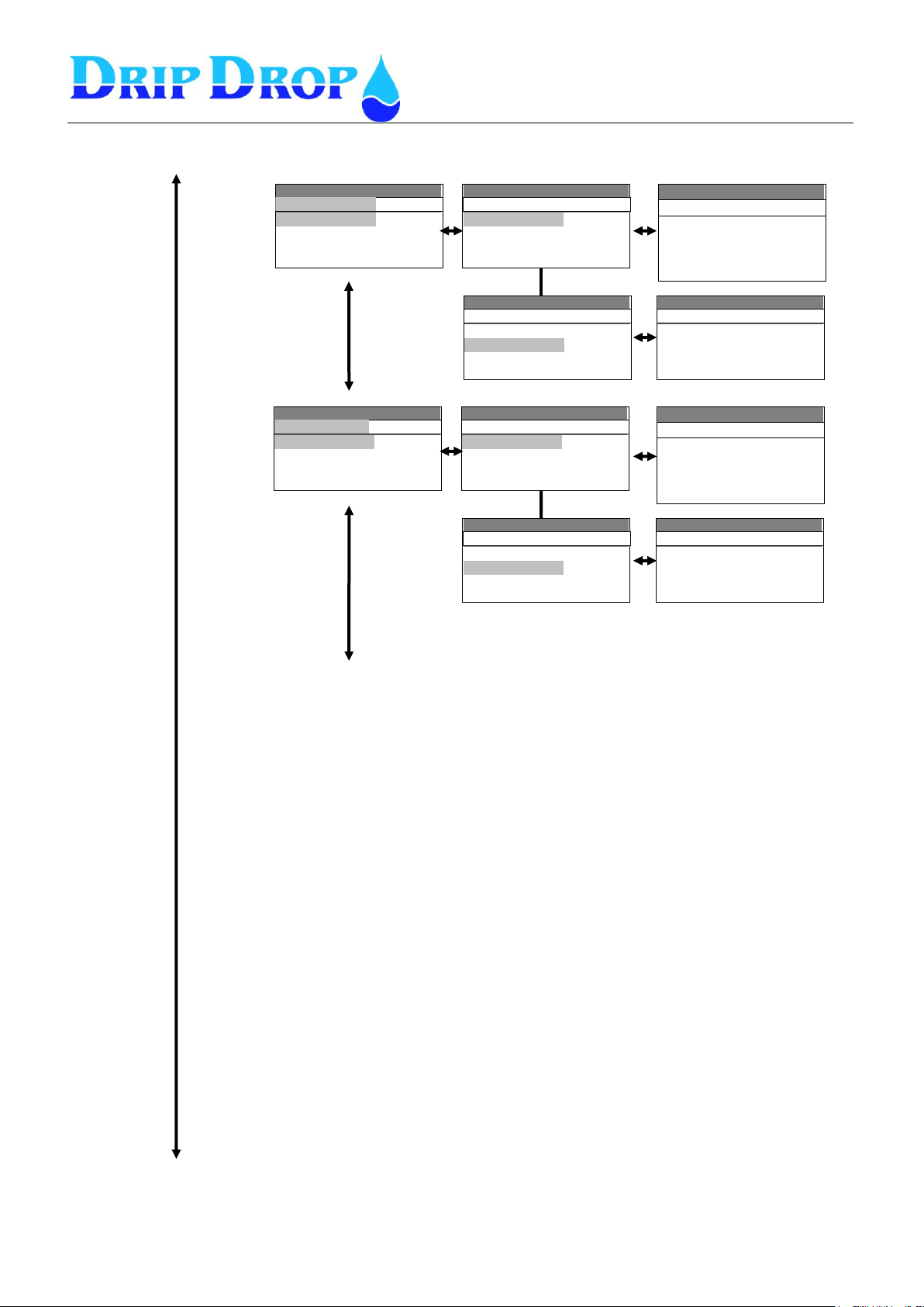
MANUAL PC-2000-W
Ver. 30.56.12-UK/101208
Page 67 (71)
Station settings cont.
Settings( ) v30.56.XX
Inställningar ( ) v30.56.XX
▪Mixer 1 settings
▪Mixer 2 settings
▪Inflow calculation
▪Overflow calculation
dStation settings
Settings( ) v30.56.XX
Inställningar ( ) v30.56.XX
▪Level controlled
▪Timer controlled
Mixer 1 settings
Settings( ) v30.56.XX
Inställningar ( ) v30.56.XX
▪Level controlled
▪Timer controlled
Mixer 1 settings
Settings( ) v30.56.XX
Inställningar ( ) v30.56.XX
-Type: in use
-Start after[h]: 0
-Runtime[s]: 0
-Block if pump ON : Yes
Timer controlled
Settings( ) v30.56.XX
Inställningar ( ) v30.56.XX
-Type: Empying
-Start cycles: 0
-Start level[m]: 0.00
-Start delay[s]: 0
-Runtime[s]: 0
Level controlled
Settings( ) v30.56.XX
Inställningar ( ) v30.56.XX
▪Mixer 2 settings
▪Inflow calculation
▪Overflow calculation
▪Spec. Cons.: Flow-c
Station settings
Settings( ) v30.56.XX
Inställningar ( ) v30.56.XX
▪Level controlled
▪Timer controlled
Mixer 2 settings
Settings( ) v30.56.XX
Inställningar ( ) v30.56.XX
▪Level controlled
▪Timer controlled
Mixer settings
Settings( ) v30.56.XX
Inställningar ( ) v30.56.XX
-Type: in use
-Start after[h]: 0
-Runtime[s]: 0
-Block if pump ON : Yes
Timer controlled
Settings( ) v30.56.XX
Inställningar ( ) v30.56.XX
-Type: Empying
-Start cycles: 0
-Start level[m]: 0.00
-Start delay[s]: 0
-Runtime[s]: 0
Level controlled
Page 68
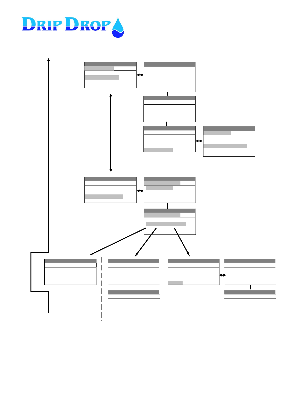
MANUAL PC-2000-W
Ver. 30.56.12-UK/101208
Page 68 (71)
Settings( ) v30.56.XX
Inställningar ( ) v30.56.XX
▪Mixer 2 settings
▪Inflow calculation
▪Overflow calculation
▪Spec. Cons.: Flow-c
Station settings
Settings( ) v30.56.XX
Inställningar ( ) v30.56.XX
-Inflow calc.time[s]: 0
-Capac. calc. time[s]: 0
-Start delay[s]: 5
-Stop delay[s]: 3
-Inflow level[m]: 0.5
Inflow calculation
Settings( ) v30.56.XX
Inställningar ( ) v30.56.XX
-2 pump comp,[%]: 90
-3 pump comp.[%]: 90
-4 pump comp.[%]: 90
▪Pit description
Inflow calculation
Settings( ) v30.56.XX
Inställningar ( ) v30.56.XX
-Level 0 [m]: 0.00
-Area 0 [m2]: 0.00
…Level 0-8 and Area 0-8…
-Level 8 [m]: 0.00
-Area 8 [m2]: 0.00
Pit description
Settings( ) v30.56.XX
Inställningar ( ) v30.56.XX
-Trigger: Sensor
-Method: lock on inflow
Overflow calculation
Settings( ) v30.56.XX
Inställningar ( ) v30.56.XX
▪Mixer settings
▪Inflow calculation
▪Overflow calculation
▪Spec. Cons.: Flow-c
Station settings
Settings( ) v30.56.XX
Inställningar ( ) v30.56.XX
-Trigger: Sensor
-Method: Value AI2
Overflow calculation
Settings( ) v30.56.XX
Inställningar ( ) v30.56.XX
-Trigger. float
-Metod: double exp.
-Unit: m3/h
-Exponent1: 0.000
Overflow calculation
Settings( ) v30.56.XX
Inställningar ( ) v30.56.XX
-Trigger: Sensor
-Method: Complex table
-Unit: m3/h
▪Level 1.2.3.4.5.6.7.8.9.10
Overflow calculation
Settings( ) v30.56.XX
Inställningar ( ) v30.56.XX
-Trigger: Float
-Method: Lock on inflow
Overflow calculation
Settings( ) v30.56.XX
Inställningar ( ) v30.56.XX
-Exponent 1: 0.000
-Constant 1: 0.000
-Exponent 1: 0.000
-Constant 1: 0.000
Overflow calculation
Settings( ) v30.56.XX
Inställningar ( ) v30.56.XX
-Level [mm]: 000
-Flow [m3/h]: 000.0
-Exponent: 0.000
Level 1
Settings( ) v30.56.XX
Inställningar ( ) v30.56.XX
-Level [mm]: 000
-Flow [m3/h]: 000.0
-Exponent: 0.000
Level 2
Settings( ) v30.56.XX
Inställningar ( ) v30.56.XX
-Inflow calc. Time[s]:0
-Capac.Calc.time[s]:0
-Start delay[s]:
-Stop delay[s]:
Inflow calculation
Station settings cont.
Page 69
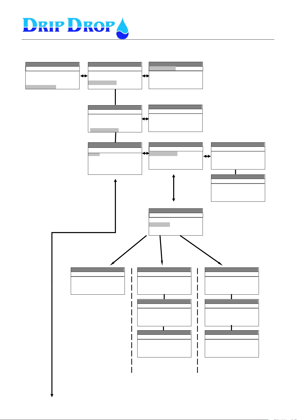
MANUAL PC-2000-W
Ver. 30.56.12-UK/101208
Page 69 (71)
Settings( ) v30.56.XX
Inställningar ( ) v30.56.XX
-0% [m]: 0.00
-100% [m]: 10.00
Level bargraph
Settings( ) v30.56.XX
Inställningar ( ) v30.56.XX
-Op. access code: ▼▼▼▼
-Sys. Access code: ▲▲▲▲
▪Level bargraph
▪Logger settings
Miscellaneous
Settings( ) v30.56.XX
Inställningar ( ) v30.56.XX
▪RS232 settings
▪RS485 settings
▪Clock settings
▪Reset/Erase.
▪Default settings
Miscellaneous
Settings( ) v30.56.XX
Inställningar ( ) v30.56.XX
-Op. access code: ▼▼▼▼
-Sys. Access code: ▲▲▲▲
▪Level bargraph
▪Logger settings
Miscellaneous
Settings( ) v30.56.XX
Inställningar ( ) v30.56.XX
-Sample interval: 5 min
-Logger type: Stack
Logger settings
Settings( ) v30.56.XX
▪Comm. settings
▪Connection
RS232
Settings( ) v30.56.XX
Inställningar ( ) v30.56.XX
-Baud rate: 1200
-Parity: none
-Stop bits: 1
-Protocol: COMLI
Comm.settings
Settings( ) v30.56.XX
Inställningar ( ) v30.56.XX
-Stop bits: 1
-Protocol: COMLI
-Device address: 1
-Station ID: 1
Comm.settings
Settings( ) v30.56.XX
Inställningar ( ) v30.56.XX
▪Comm.settings
▪Connection
RS 232 settings
Settings( ) v30.56.XX
Inställningar ( ) v30.56.XX
-Link: GSM-SMS
-Reset modem t[m]: 0
-Pulse duration[s]: 0
-H:&FE0V1Q0
Connection
Settings( ) v30.56.XX
Inställningar ( ) v30.56.XX
-PIN code: 0000
-N1:▫ ▫ ▫ ▫ ▫ ▫ ▫ ▫ ▫ ▫ ▫ ▫
-N2:▫ ▫ ▫ ▫ ▫ ▫ ▫ ▫ ▫ ▫ ▫ ▫
-N3:▫ ▫ ▫ ▫ ▫ ▫ ▫ ▫ ▫ ▫ ▫ ▫
Connection
Settings( ) v30.56.XX
Inställningar ( ) v30.56.XX
-Stn:
-Remote acknowledge: no
-Ack timeout [x10s]: 12
Connection
Settings( ) v30.56.XX
Inställningar ( ) v30.56.XX
▪I/O configuration
▪Pump settings
▪Station settings
▪Miscellananeous
..
Settings( ) v30.56.XX
Inställningar ( ) v30.56.XX
-Link: dial up
-Remote acknowledge: no
Connection
Settings( ) v30.56.XX
Inställningar ( ) v30.56.XX
-Link: dial up
-Reset modem t[m]: 0
-Pulse duration[s]: 0
-H:&FE0V1Q0
Connection
Settings( ) v30.56.XX
Inställningar ( ) v30.56.XX
-Modem type: PSTN
-N1:▫ ▫ ▫ ▫ ▫ ▫ ▫ ▫ ▫ ▫ ▫ ▫
-Idc:▫ ▫ ▫ ▫ ▫ ▫ ▫ ▫ ▫ ▫ ▫ ▫
-Answer after: 2
Connection
Settings( ) v30.56.XX
Inställningar ( ) v30.56.XX
-Alarm resend no: 0
-Retry time[s]: 0
-Callon alarm OFF : no
-Remote acknowledge:no
Connection
Miscellaneous
Page 70
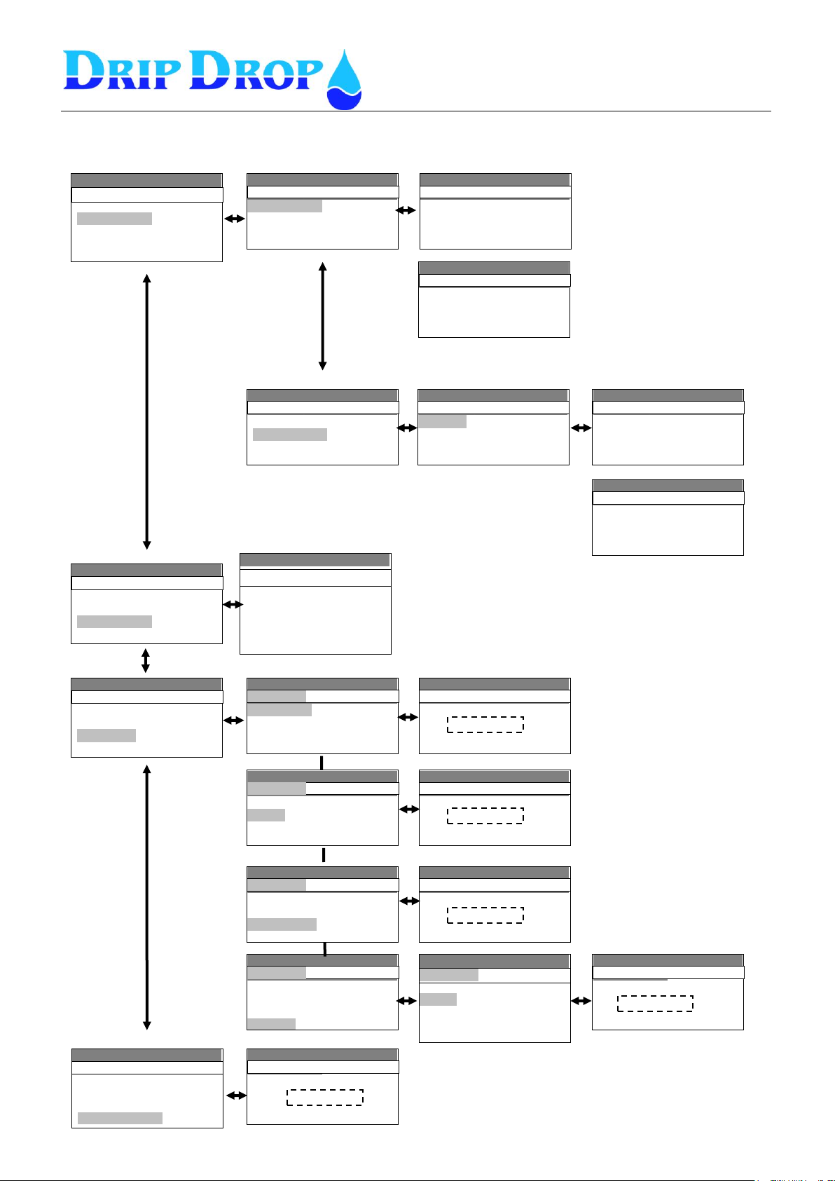
MANUAL PC-2000-W
Ver. 30.56.12-UK/101208
Page 70 (71)
Settings( ) v30.56.XX
Inställningar ( ) v30.56.XX
▪RS232 settings
▪RS485 settings
▪Clock settings
▪Reset/Erase.
▪Default settings
Miscellaneous
Settings( ) v30.56.XX
Inställningar ( ) v30.56.XX
▪Comm.settings
▪Devices on 485
RS485
Settings( ) v30.56.XX
Inställningar ( ) v30.56.XX
-Acts as: master
-Baud rare: 1200
-Parity: none
-Stop bits 1
Comm.settings
Settings( ) v30.56.XX
Inställningar ( ) v30.56.XX
-Parity: none
-Stop bits: none
-Protoco: COMLI
-Time limit[s]: 0.0
Comm.settings
Settings( ) v30.56.XX
Inställningar ( ) v30.56.XX
▪Comm.settings
▪Devices on 485
RS485
Settings( ) v30.56.XX
Inställningar ( ) v30.56.XX
▪Device 1
▪Device 2
▪Device 3
▪Device 4
Devices on 485
Settings( ) v30.56.XX
Inställningar ( ) v30.56.XX
-Type: PC-2000
-Adress: 1
-Name: ▫ ▫ ▫ ▫ ▫▫ ▫ ▫ ▫ G<
Device 1
Settings( ) v30.56.XX
Inställningar ( ) v30.56.XX
-Type: PC-200
-Adress: 2
-Name: ▫ ▫ ▫ ▫ ▫▫ ▫ ▫ ▫ G<
Device 2
Settings( ) v30.56.XX
-Date [yy/mm/dd]:
09/03/09
-Tid [hh:mm:ss]:
10:45:55
- Day: Monday
Clock setting
Settings( ) v30.56.XX
nställningar ( ) v30.56.XX
▪RS232 settings
▪RS485 settings
▪Clock settings
▪Reset/Erase.
Miscellaneous
Settings( ) v30.56.XX
Inställningar ( ) v30.56.XX
▪Logged data
▪Alarms
▪Reset floats
▪Counters
Reset/Erase
Settings( ) v30.56.XX
Inställningar ( ) v30.56.XX
▪RS485
▪Clock
▪Reset/Erase
▪Factorysettings
Miscellaneous
Settings( ) v30.56.XX
Inställningar ( ) v30.56.XX
Are you sure
Settings( ) v30.56.XX
Inställningar ( ) v30.56.XX
▪Logged data
▪Alarms
▪Reset floats
▪Counters
Reset/Erase
Settings( ) v30.56.XX
Inställningar ( ) v30.56.XX
▪Volume/Energy
▪Pump 1
▪Pump 2
▪Pump 3
▪Pump 4
Reset/Erase
Settings( ) v30.56.XX
Inställningar ( ) v30.56.XX
▪Logged data
▪Alarms
▪Reset floats
▪Counters
Reset/Erase
Settings( ) v30.56.XX
Inställningar ( ) v30.56.XX
Are you sure
Settings( ) v30.56.XX
Inställningar ( ) v30.56.XX
▪Logged data
▪Alarms
▪Reset floats
▪Counters
Reset/Erase
Settings( ) v30.56.XX
Inställningar ( ) v30.56.XX
Are you sure
Settings( ) v30.56.XX
Inställningar ( ) v30.56.XX
▪RS485
▪Clock
▪Reset/Erase
▪Factory settings
Miscellananeous
Settings( ) v30.56.XX
I Settings( )
Are you sure
Settings( ) v30.56.XX
I Settings( )
Are you sure
Miscellaneous cont.
Page 71
MANUAL PC-2000-W
Ver. 30.56.12-UK/101208
Page 71 (71)
Notes
 Loading...