

Page 1
DripDrop AB • Pipers Väg 2C • 170 73 Solna • www.dripdrop.se • Tel. +46 8 655 02 94
User manual
Version 2.12.xx/-UK
PC-200
Pump controller
Page 2

MANUAL PC-200
Ver. 2.12.xx/10/22/2010-UK
Page 2 (61)
TABLE OF CONTENTS ....................
1 DESCRIPTION ............................................................................................................................................................ 5
1.1 GENERAL ............................................................................................................................................................... 5
1.2 OPERATOR UNIT .................................................................................................................................................... 5
2 LOG IN – ACCESS CODE ......................................................................................................................................... 5
3 MENU OVERVIEW .................................................................................................................................................... 6
3.1 MAIN MENU – STATUS WINDOWS, SETTINGS AND ALARM HANDLING ................................................................... 6
3.1 ▼ ▲ MENU OVERVIEW – SYSTEM SETTINGS ......................................................................................................... 7
4 STATUS MENUS ......................................................................................................................................................... 8
4.1 START WINDOW (LEVEL) ................................................................................................ ................................ ....... 8
4.2 ANALOGUE INPUT 2 (FREE CHOICE) ....................................................................................................................... 8
4.3 VOLTAGE INPUT (PHASE MEASUREMENT) .............................................................................................................. 8
4.4 ATTENDANCE CHECK (PERSON- / INTRUDER ALARM) ............................................................................................. 8
4.5 PUMP STATUS ........................................................................................................................................................ 9
4.6 OVERFLOWS (ONLY SHOWN IF OVERFLOW FUNCTION IS ACTIVATED) .................................................................... 9
4.7 FLOW STATUS ........................................................................................................................................................ 9
5 SYSTEM SETTINGS ................................................................................................................................................ 10
5.1 APPLICATION ....................................................................................................................................................... 11
5.2 I/O SETTINGS ....................................................................................................................................................... 12
5.2.1 Digital inputs ................................................................................................................................................. 13
5.2.2 Digital outputs ............................................................................................................................................... 19
5.2.3 Pulse input ..................................................................................................................................................... 20
5.2.4 Analogue inputs (mA)..................................................................................................................................... 21
5.2.5 Voltage inputs ................................................................................................................................................ 22
5.2.6 Current inputs ................................................................................................................................................ 23
5.2.7 Temperature protection.................................................................................................................................. 25
5.3 PUMP SETTINGS ................................................................................................................................................... 26
5.3.1 Start and stop levels ....................................................................................................................................... 27
5.3.2 Alternation, running time and break time ...................................................................................................... 27
5.3.3 Running confirmation .................................................................................................................................... 27
5.3.4 Setting of motor currents................................................................................................................................ 28
5.3.5 Times / delay for pumps ................................................................................................................................. 29
5.4 STATION SETTINGS .............................................................................................................................................. 30
5.4.1 Alternation type of pumps .............................................................................................................................. 30
5.4.2 Level alarm settings (Low and high level alarms) ......................................................................................... 30
5.4.3 AI 2 Setpoints, Analogue setpoints ................................................................................................................. 31
5.4.4 Mixer settings ................................................................................................................................................. 32
5.4.5 Attendance check (Person alarm or Intruder alarm) ..................................................................................... 33
5.5 VOLTAGE RELAY ................................................................................................................................................. 34
5.6 MISCELLANEOUS ................................................................................................................................................. 36
5.6.1 Communication .............................................................................................................................................. 36
5.6.2 Trusted login .................................................................................................................................................. 39
5.6.3 Operator password ........................................................................................................................................ 39
5.6.4 System password ............................................................................................................................................ 39
5.6.5 Clock setting................................................................................................................................................... 39
5.6.6 Default settings ............................................................................................................................................. 39
5.6.7 Erase alarms .................................................................................................................................................. 40
5.6.8 Erase counters ............................................................................................................................................... 40
5.6.9 Erase runtimes ............................................................................................................................................... 40
5.6.10 Contrast ..................................................................................................................................................... 40
5.7 LOGIN / LOGOUT.................................................................................................................................................. 40
6 LEVEL SETTINGS ................................................................................................................................................... 41
7 MANUAL START AND STOP OF PUMPS ........................................................................................................... 41
8 ALARM STATUS ...................................................................................................................................................... 42
Page 3

MANUAL PC-200
Ver. 2.12.xx/10/22/2010-UK
Page 3 (61)
8.1 ALARM HANDLING............................................................................................................................................... 42
8.2 NEW ALARMS ...................................................................................................................................................... 42
8.3 ACTIVE ALARMS .................................................................................................................................................. 43
8.4 ALL ALARMS ....................................................................................................................................................... 43
9 SMS-FUNCTIONS - USE OF MOBIL PHONE ..................................................................................................... 44
9.1 ALARM BY SMS MESSAGES ................................................................................................................................. 44
9.2 REMOTE CONFIRMATION OF THE ALARMS ............................................................................................................ 44
9.3 TO ASK QUESTIONS VIA SMS TEXTS .................................................................................................................... 45
10 I/O-LIST, SIGNAL TABLE ......................................................................................................................................... 46
11 CONFIGURATION TABLE ........................................................................................................................................ 47
12 MENU STRUCTURE – SETTINGS ............................................................................................................................ 50
NOTES ................................................................................................................................................................................ 61
Page 4

MANUAL PC-200
Ver. 2.12.xx/10/22/2010-UK
Page 4 (61)
Copyright © 2005 DripDrop AB. All rights reserved.
This manual and all the information within may not be used or copied in any form without the
written consent of DripDrop AB.
Changes
The content of this manual is for informational use only and can be subject to changes
without prior notice.
DripDrop AB products are developed continuously and we reserve the right to alter technical
specifications without prior notice.
Liability
DripDrop AB assumes no responsibility or liability for errors or incorrect information that may
appear in this document.
DripDrop AB assumes no responsibility or liability for loss of profit, working deficits or any
other indirect losses due to erroneous use or application of the information exposed in this
manual.
Page 5

MANUAL PC-200
Ver. 2.12.xx/10/22/2010-UK
Page 5 (61)
1 Description
1.1 General
The pump controller PC-200 is an advanced computer controlled device to control and supervise up to
3 pumps. It is built up of a combined operator and I/O unit for connecting all digital and analogue
signals used by the unit. The level in the sump is detected by a 4-20 mA level sensor (chapter 5.2.4), or
by the use of level switches to start and stop the pumps (chapter 5.2.1).
The controller can handle a mixing device and has an integrated voltage supervision relay.
The unit has one communications port RS 232 for communication with radio/PSTN modems or
a GSM-modem to send SMS-text messages or to communicate with a supervision and SCADA
system.
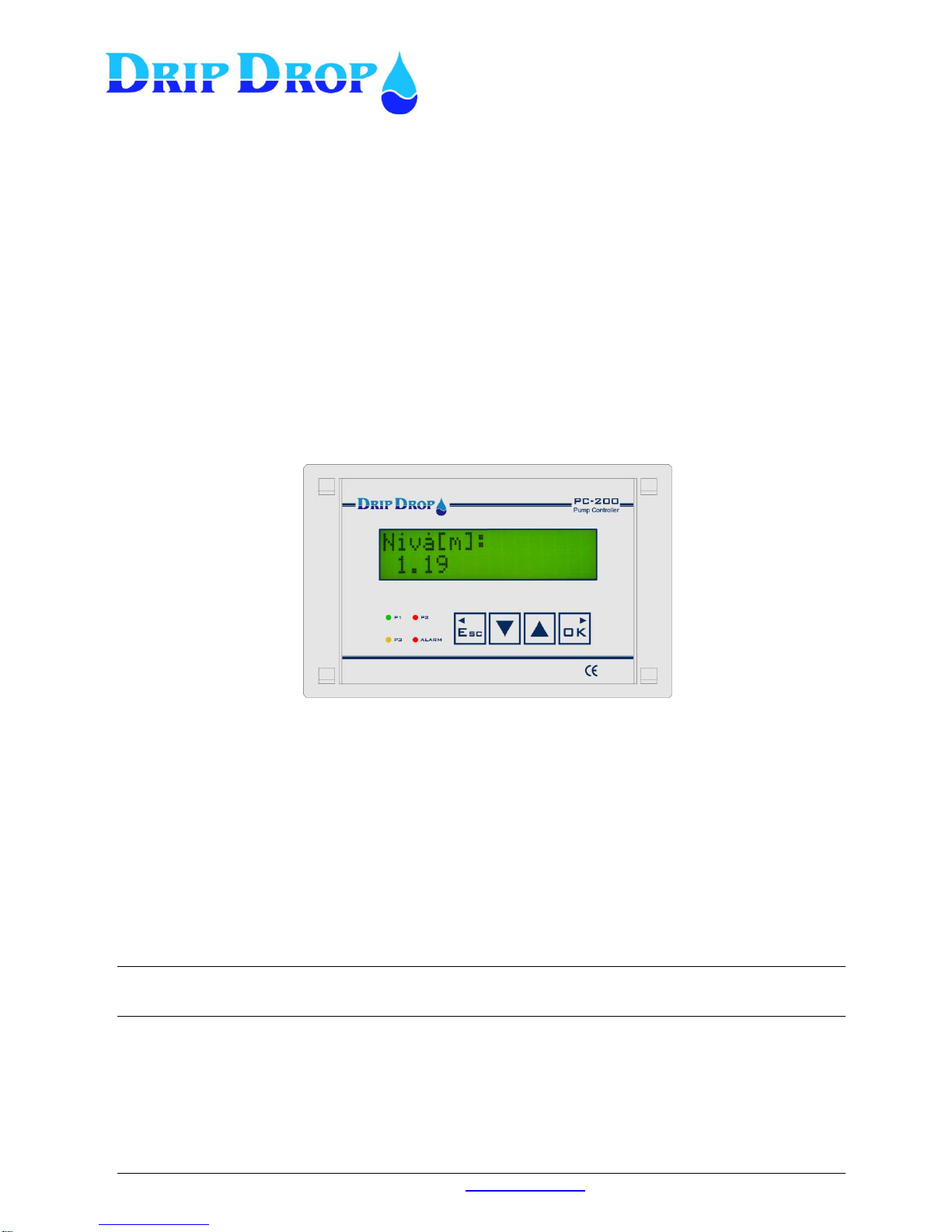
1.2 Operator unit
The operator unit is mounted in the front door of a cabinet and has 4 control keys for handling,
configuration and alarm. There are 4 light emitting diodes for indication of alarms and status and an
alphanumeric display with 2 x 16 signs for displaying all information.
Front panel
2 Log in – Access code
For looking at information about pumps, running times or alarm you can go directly to the actual
information menus. But to make changes or acknowledge alarms a.s.o. you need to enter an access
code depending of what you want to do. The unit is delivered with two different access codes:
1. Operator code – allows acknowledgement of alarms. The code is ZZZZ (▼▼▼▼)
2. System code – allows changes of for example start and stop values or configuration of the unit.
The code is 0000 (▲▲▲▲)
The access codes can be changed under ”System settings”
When you enter a menu and want to change any value, the access code prompt will show when you
press the OK key to enter the changing position. When the prompt shows up you set the actual code
and accept with the OK key you enter the changing position and can make the changes you desire.
The unit will automatically log out 5 minutes after the last time you pressed a key.
If the function “Trusted logged in” is activated no log out will be made.
Confirm choice, enter submenus, and to go
from the start menu to the main menu.
Exit the menus and go to the left.
Used to step downwards in the submenus, and
to change values to be set.
Used to step upwards in the submenus and to
change the values to be set.
Indication diode ”P1-P3”
3 multicolour diodes show the
status for each pump.
¤ Green shows pump is running.
¤ Red shows pump alarm
¤ Orange shows pump ”Not Auto”
Indication diode ”Alarm”
1 red diode shows the alarms.
¤ Red ”blinking” not ackn. alarm.
¤ Red ”fixed” active, ackn. alarm.
Page 6
MANUAL PC-200
Ver. 2.12.xx/10/22/2010-UK
Page 6 (61)
D a t e : 0 5 / 0 3
T i m e : 1 2 . 3 5
O v . f l o w [ h ]
O v . f l o w N o s
V o l u m e [ m 3 ] :
0
L e v e l [ m ] :
P 1 P 2
O n o f f
A I 2 [ % ] :
1 . 1 9
U R U S U T
0 2 3 0 2 3 0 V
P e r s . Ala r m ON
8 0 0 s e c
P 1 O p h r s . . : 5
P 1 N o s . : 3 5
P 2 O p h r s . : 5
P 2 N o s . : 35
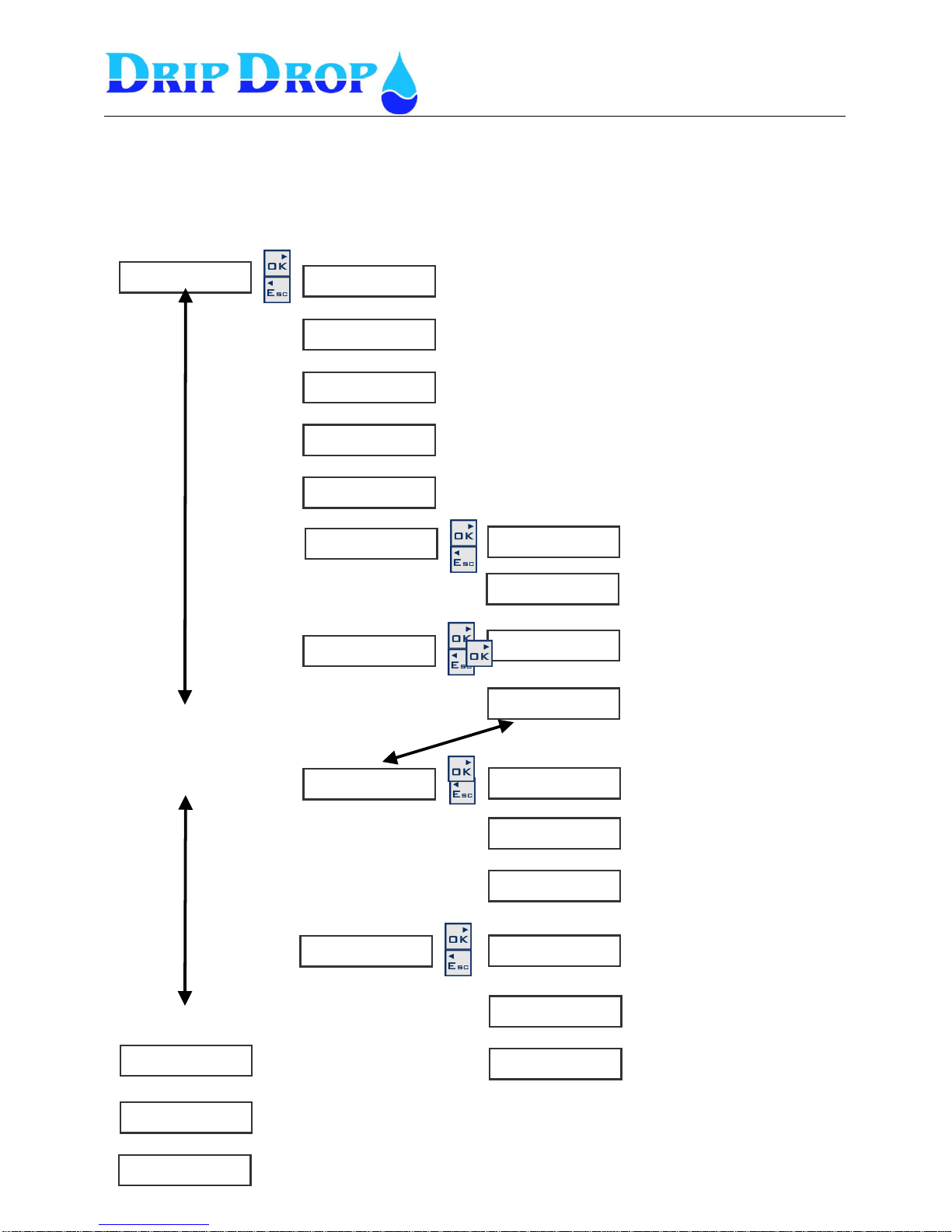
3 Menu overview
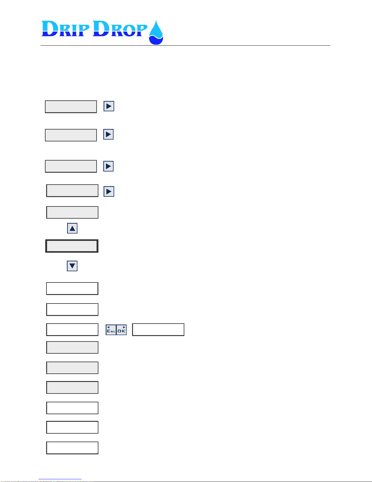
3.1 Main menu – Status windows, settings and alarm handling
A l a r m s t a t u s ►
M a n . C o n t r o l ►
L e v e l s e t t i n g s ►
S y s t e m s e t t i n g s ►
▼▲
A t t e n d a n c e ►
▼▲
▼▲
▼▲
▼▲
▼▲
▼▲
▼▲
▼▲
▼▲
▼▲
▼▲
▼▲
This is the start window, which always is shown.
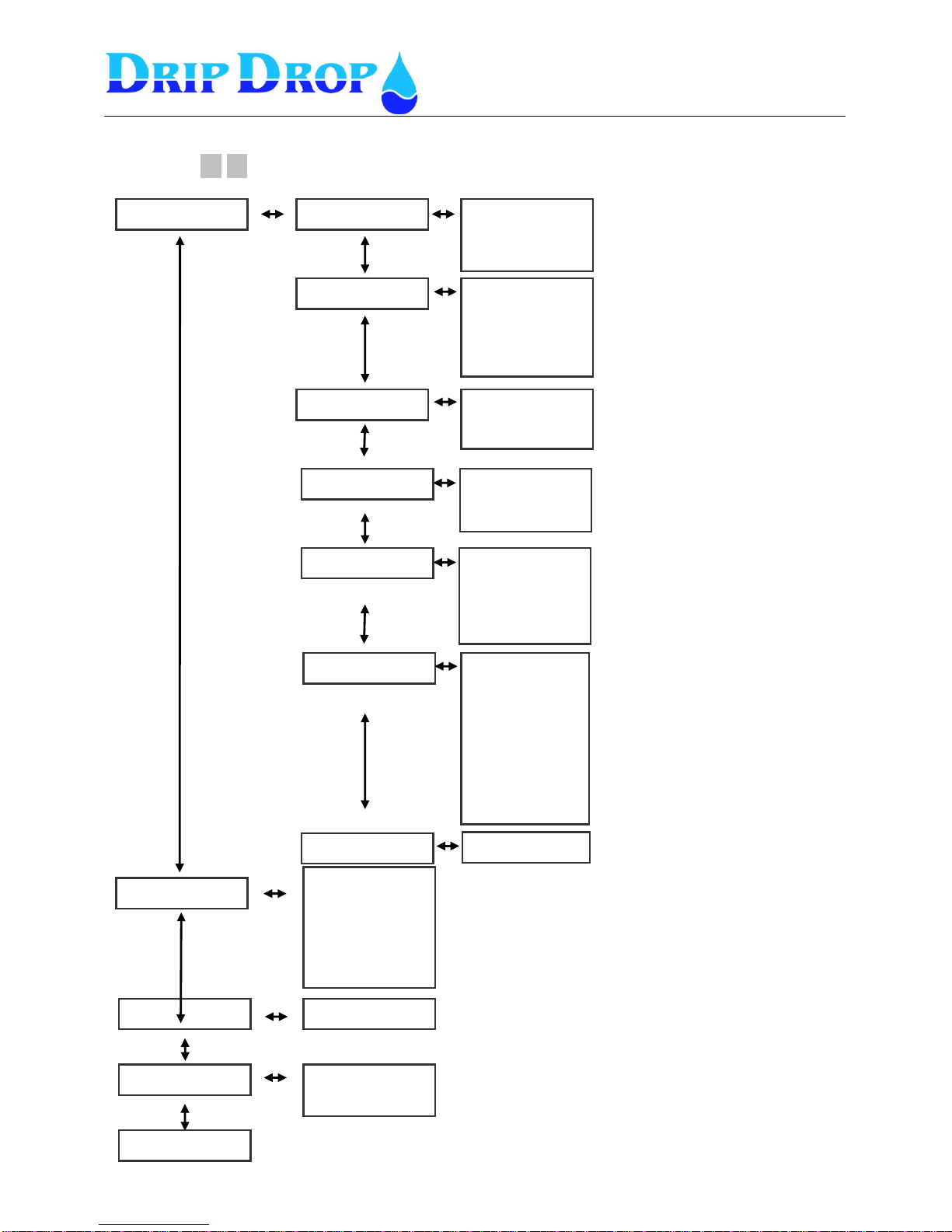
In the menu for the system settings, all settings for Applications, In/outputs, Levels,
Pumps, Station, Voltage relay and miscelaneous settings like, communications etc.
are made. See system settings chapter 3.2 and 5.
In this menu you have fast access to set the start/ stop levels of the pumps and to
the alarm level for low and high level. See level settings chapter 7.
Menu to start and stop pumps manually.
Can only be hand started if the conditions allow this. See chapter 7
The menues for The UP key takes you to settings, alarm handling and manual control
of pumps.
The DOWN key takes you to all status windows. NOTE tat the shadowed display
windows will always be shown not depending on the setting of the functions. Not
shadowed will only be shown if the functions are activated.
Menu to look at and acknowledge alarms and look at the alarm history. See
further chapter 8
Shows actual value for analogue input 2. If input 2 is activated. See chapter 4
Shows actual voltage between all phases and neutral if the voltage relay function is
activated. See further 5.2.5 and 5.5
Shows actual status for person alarm if the function is
activated. Chapter 5.4.5
The pumpstatus window shows if the pum is running or not. If the pump current
function is activated the pump current will be display for running pump.
Shows total running time and number of starts for pump 1.
Shows total running time and number of starts for pump 2.
Shows total overflow time and numbers of overflows. Is only shown if the overflow
float function is activated. See further 5.2.1
Shows actual flow on pulse input. Only shown if pulse input is activared
See 5.2.3
Shows total pumped volume onnumber pulse input. Show only if pulse input is
activated. See 5.2.3
F l o w [ m 3 / h ] :
0 . 0
Page 7
MANUAL PC-200
Ver. 2.12.xx/10/22/2010-UK
Page 7 (61)
D i g i t a l i n p u t s
D i g i t a l o u t p u t s
C o u n t e r
A n a l o g u e i n p u t s
V o l t a g e i n p u t s
C u r r e n t i n p u t s
A l t e r n a t i o n
L e v e l a l a r m s
A I 2 s e t p o i n t s
M i x e r s e t t i n g s .
N o m i n a l [ V ] ( L - N)
F a i l b r e a k t i m e
P h a s e r o t a t i o n
U n d e r v o l t a g e
O v e r v o l t a g e
U n b a l a n c e
C o m m u n i c a t i o n
T r u s t e d l o g i n
O p e r a t o r p a s s w o r d
S y s t e m p a s s w o r d
C l o c k s e t t i n g s
D e f a u l t s e t t i n g s
E r a s e a l a r m s
E r a s e c o u n t e r s .
E r a s e p u l s e i n p u t .
R e s e t o p . h r s .
C o n t r a s t
L o g i n / l o g o u t
P a s s w o r d
Z Z Z Z
P 1 M a n u a l s t a r t
N o t a l l o w e d
S t a r t P 2
* A c t i v e a l a r m s
A l l a l a r m s
D a t e : 0 5 / 0 3
T i m e : 1 2 . 3 5
N u m b e r o f p u m p s
M a x p u m p n u m b e r
F u n c t i o n
A d v a n c e d m o d e
P u m p 1
P u m p 2
P u m p 3
T i m e / D e l a y s
S t a r t l e v e l P 1
S t o p l e v e l P 1
S t a r t l e v e l P 2
S t o p l e v e l P 2
S t a r t l e v e l P 3
S t o p l e v e l P 3
A l a r m l o w l e v e l
A l a r m h i g h l e v e l
3.2 ▼ ▲ Menu overview – System settings
4
A p p l i c a t i o n ►
I / O s e t t i n g s ►
P u m p s e t t i n g s ►
S t a t i o n s e t t i n g s .►
V o l t a g e r e l a y .►
M i s c e l l a n e o u s .►
M a n u a l c o n t r o l ►
A l a r m s t a t u s ►
S y s t e m s e t t i n g s ►
L e v e l s e t t i n g s ►
Page 8
MANUAL PC-200
Ver. 2.12.xx/10/22/2010-UK
Page 8 (61)
L e v e l [ m ]:
1 . 19
A I 2 [ % ]:
1.19
U R US UT
2 3 1 2 3 0 2 3 0 V
P e r s . A l a r m O N
8 0 0 s e c 0
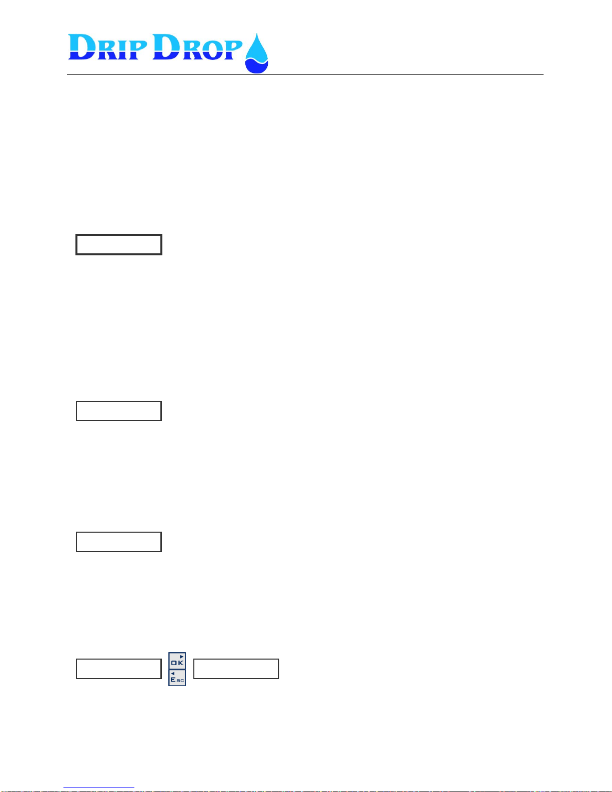
Status menus
When in the normal standby mode the controller will show the actual level in the pump pit at all times.
By pressing the down arrow ▼you will have direct access to status windows which are organized in a
loop, where, by each pressing of an arrow button you will see the next status window in the loop.
In this menu you will find information about the level, pump and station status etc.
4.1 Start window (Level)
This is the window that is always displayed when the unit is in normal working mode.
4.2 Analogue input 2 (Free choice)
Will appear only if analogue input 2 is activated and configured.
Actual value for the analogue input 2 is shown in the next window. As this input is editable regarding
texts, units and scaling and will show the configured values.
4.3 Voltage input (phase measurement)
The voltage reading for each phase (Phase-N) will be shown if the voltage relay is activated and the
corresponding wiring is done (three phases and neutral)
4.4 Attendance check (person- / intruder alarm)
If the attendance check function is activated, personal alarm or intruder alarm, in this window the
status for the function is shown, on/off and the remaining delay time for the alarm to go active.
A t t e n d . c h e c k ►
▼▲
▼▲
▼▲
▼▲
▼▲
▼▲
▼▲
▼▲
If the up ▲ arrow is pressed you will access the settings and alarmwindows
in the main menu.
If the down ▼ arrow is pressed you will access the status windows in the
main menu.
More information under system settings page 21
More information under system settings page 21
More information under system settings page 26
Page 9
MANUAL PC-200
Ver. 2.12.xx/10/22/2010-UK
Page 9 (61)
P 1 P 2 P 3
o f f o n o n
P 1 O p . h : 5
P 1 N o s : 3 5
P 2 O p .h: 5
P 2 N o s : 3 5
O v . f l o w [ h ] 0
O v . F l o w N o s 3 1
F l o w [ m 3 / h ] :
0 . 0
V o l u m e [ m 3 ] :
0
P 3 O p . h : 5
P 3 N o s : 3 5
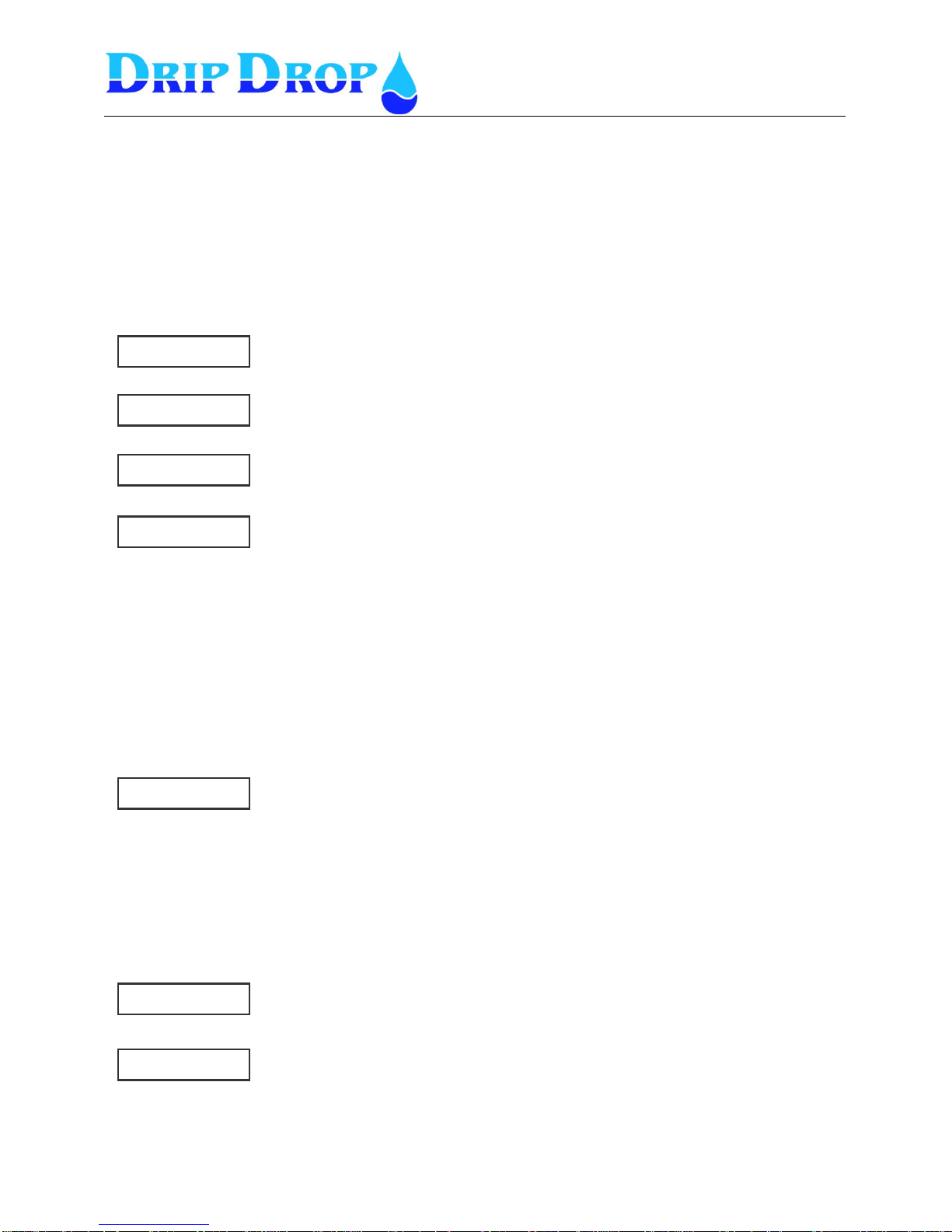
4.5 Pump status
In the pump status windows the information about all pumps is available.
The first information window shows if pumps are running, and if they are in auto or not in auto.
The following windows show the total values for operating hours and number of starts for each pump.
This information is only available in these windows. Only pumps that are used are shown.
4.6 Overflows (only shown if overflow function is activated)
If the overflow switch function is activated, the total overflow duration and total number of overflows
will be shown.
4.7 Flow status
If the digital pulse counter input for flow is used, in these two windows you will see the actual instant
flow and the accumulated total volume pumped.
▼▲
▼▲
▼▲
▼▲
▼▲
▼▲
▼▲
▼▲
▼▲
▼▲
Shows if the pumps are on/off.
If the current measurement is activated when the pump is on the pump
current will be shown.
If the a pump is Not in auto this will be shown by the two vertical lines
surrounding thepump number │P1│.
In the second pump status window the total operation hours and number of
starts for pump 1 will be shown.
The following windows will show the corresponding values for pump 2 and 3, if
used.
If the corresonding digital input for overflow detection is activated , this
window will show the total duration of overflowing conditions and the number
occured overflows.
The instant actual flow will be shown, according to the configuration of the digital
pulse input for flow measured in m3/h or l/s.
The total pumped volume will be shown in m3/h.
Page 10
MANUAL PC-200
Ver. 2.12.xx/10/22/2010-UK
Page 10 (61)
N u m b e r o f p u m p s
◄ 3
F u n c t i o n
◄◄◄ ░ N o t i n u s e
5 System settings
The unit is delivered with a factory setting, for a fast start up of a pumping station with the most used
functions activated. To adjust the controller to the application you need to configure and activate I/O s
and functions according to the specific use.
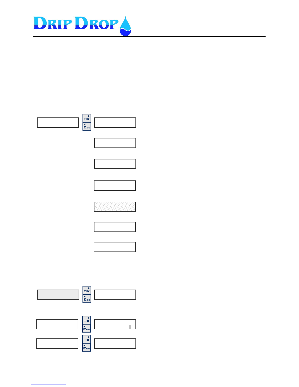
The system setting menu is built up in logic split sub menus. When you enter system settings, 7 sub
menus will be available.
In this part the description of how to enter the different submenus and how change values is made.
During configuration of the unit it is convenient to follow the logical structure of the submenus
How to change values in the setting menus
Application type – here you set the number of pumps in
the station and how many pumps are allowed to run.
I/O setting – here is set how in and outputs are to be used.
Pump settings – here all setting for each pump is done for
start and stop levels, alternation etc..
Station setting – here all settings for alarm levels, mixer
functions are made.
Voltage relay – here the settings of how you measure the
phases of the power supply are done.
Miscelaneous – Settings for default settings,
communication settings , clock settings , alarms etc.
Login/Logout – Here log in with access codes are done.
S y s t e m s e t t i n g s ►
▼▲
A p p l i c a t i o n ►
I / O s e t t i n g s ►
▼▲
P u m p s e t t i n g ►
S t a t i o n s e t t i n g ►
▼▲
V o l t a g e r e l a y ►
M i s c e l a n e o u s ►
▼▲
L o g i n / L o g o u t ►
▼▲
▼▲
How you move in the menues?
To move in the menues you use the ▼▲keys.
To enter a menu you use the OK key.
To leave a menu you use the Esc key.
S y s t e m s e t t i n g s ►
A p p l i c a t i o n ►
A p p l i c a t i o n ►
How to change values?
Move in to the menu window where you want to change a
value and press the OK key.
You will see the actual value with blinking grey square.
To change a value go up and down with the ▼▲keys
changing the numeric value or toggling between options,
then press OK to accept the choice.
To leave a menu you use the Esc key.
1.P 1 N o t i n a u t o ►
◄◄
▲
▼
Page 11
MANUAL PC-200
Ver. 2.12.xx/10/22/2010-UK
Page 11 (61)
N u m b e r o f p u m p s
◄ 3
A d v a n c e d m o d e
◄ Y e s
M a x p u m p n u m b e r
◄ 2
F u n c t i o n
◄ e m p t y i n g
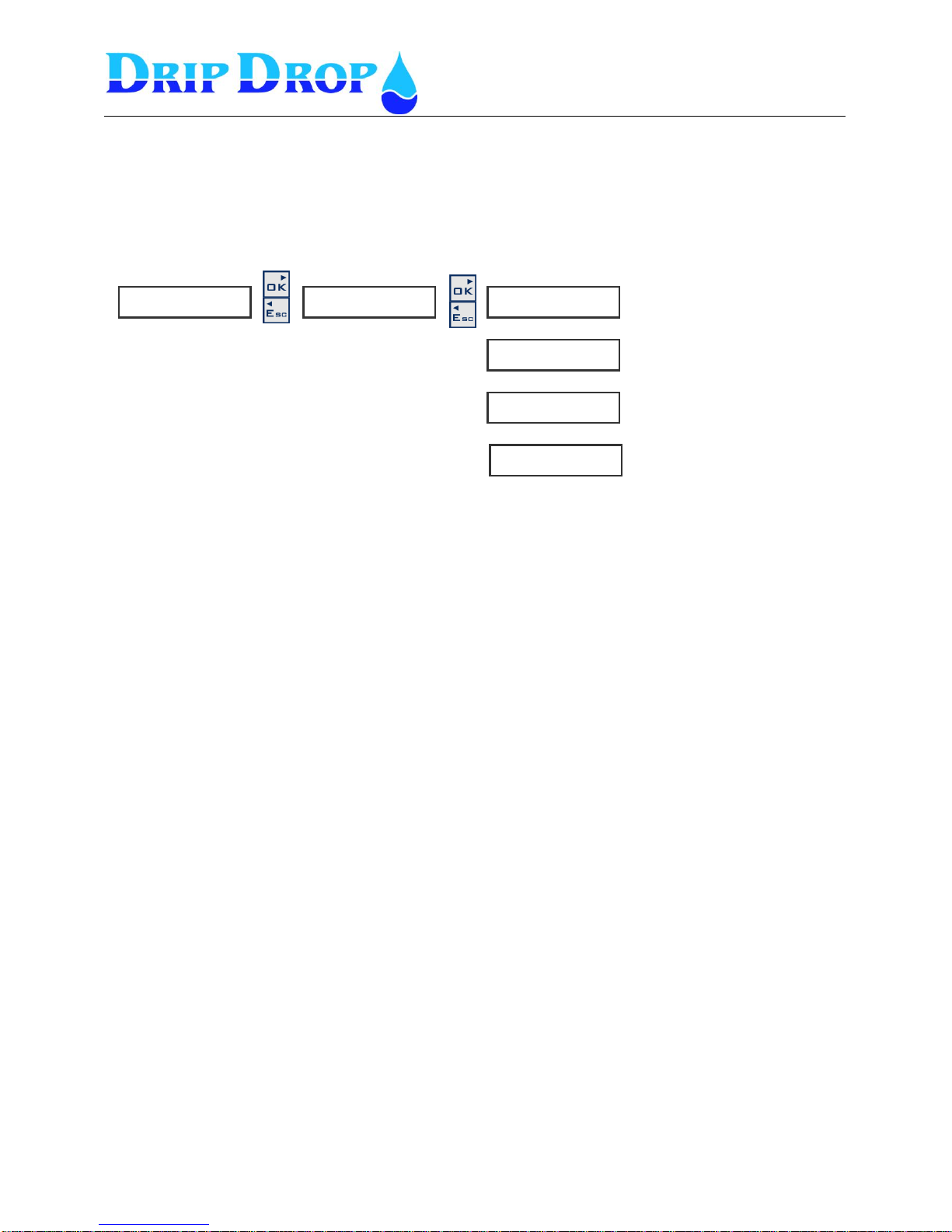
5.1 Application
The pump controller PC-200 is made to control up to 3 pumps. In the application menu you set how
many pumps the station has and how many of these pumps are allowed to run at the same time.
The unit can be configured to control the pumps with only level floats.
Advanced mode –
The advanced / not advanced mode is a mean to with just one simple settings change can convert an
advanced pump controller with many functions, to a simple controller with only basic pump control
functions.
Menu - Application
Here you set how many pumps
the station has.
Here you set how many pumps
are allowed to run at the same
time.
Here you set if the pumps are
used for filling or emptying of
pumpsump.
Here you set if you want the
unit for advanced (all functions)
mode or Basic (just the most
▼▲
▼▲
A p p l i c a t i o n ►
▼▲
S y s t e m s e t t i n g s . ►
When you are in a menu where you want to
change a value you choose the parameter you
want to change and enter the changing mode by
pressing the OK key.
Now the cursor will flash in front of the value you
want to change. Use the ▲kay to see the
alternatives and accept wanted alternative with
the OK key.
Advanced mode –NO ( Basic mode )
In Basic mode you will access the following basic
functions:
- Start and stop functions for 1 to 3 pumps.
- Alternation of pumps
- Use of analogue level sensor or level switches
- Comunication and sending of SMS alarms
- One digital pulse counter for flow, energy or rain.
- Alarm handling with alarm history (up to 15 alarms).
Advanced mode –YES
In advanced mode you will access the following
additional functions:
- One additional analogue input (free choice) with
alarm set points
- Voltage relay
- Current measurement and/or running confirmation
- Inputs for the pumps termoswitches
- Mixer functions
- Attendance check
Page 12

MANUAL PC-200
Ver. 2.12.xx/10/22/2010-UK
Page 12 (61)
5.2 I/O Settings
The unit has following in and outputs:
- 10 Digital inputs
- 7 Digital outputs
- 1 Digital pulse counter
- 2 Analogue inputs (4-20 mA)
- 3 Voltage inputs
- 3 Current inputs (5 A current transformers)
- 3 Temperature protection inputs (digital)
All these In and Outputs are predefined for what they are used for, but you have to select if they are to
be used or not, which shall generate alarms, signal delays, measuring ranges for analogue inputs etc.
For a complete overview of all In and Outputs refer to the table in chapter 10.
Page 13
MANUAL PC-200
Ver. 2.12.xx/10/22/2010-UK
Page 13 (61)
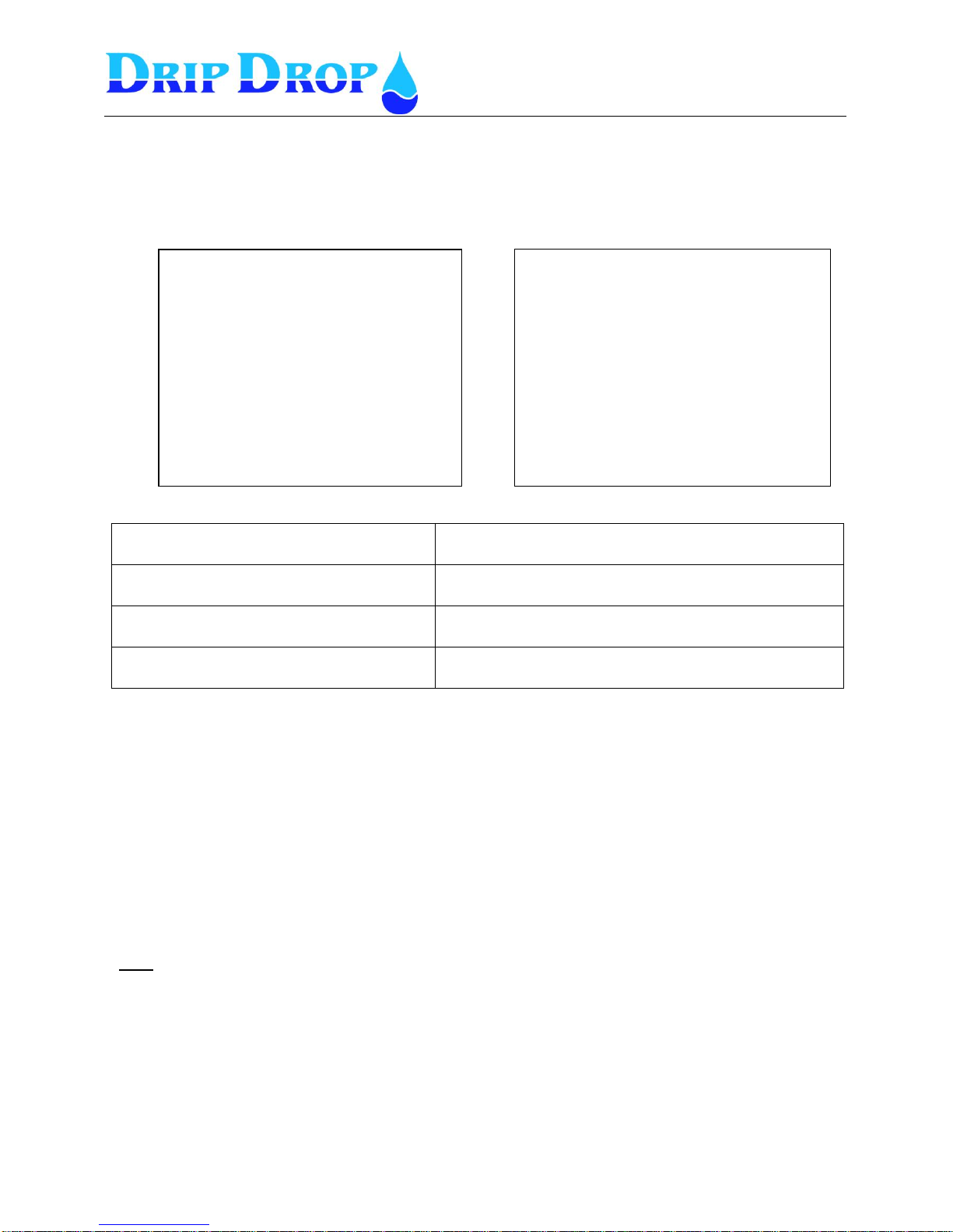
5.2.1 Digital inputs
There are totally 10 digital inputs 24 VDC available according to the list below:
1-2 Pumps 3 Pumps
Each of these inputs has following choices to be set:
Function: in use / not in use -
You can choose not to use the input.
Signal type: NC/NO
Here you specify if the input is NC or NO.
NC = normally closed and NO = normally open
Alarm function
Here you specify if you want to generate an alarm or
not, Yes or No.
Signal delay[s]:
This is a delay of the signal activation.
Backup operation / Level switch operation
DI 7 low level switch and DI 8 High level switch can be used to start and stop the pumps;
1. If level sensor is used this function can be used as a security backup to start and stop the pumps
if there is a problem with the level measuring.
2. If NO level sensor is used, the means of start and stop of the pumps will be with level switches.
With the start switch the first pump in the alternation cycle will start and it will stop with the
low level switch. If the level keeps increasing when the first pump is started (start level switch
is still active) after predefined time (see 5.3.5 Max. time starts ) a second pump will start,
when the low level switch is reached the pumps will stop with a time delay between the stops
(see 5.3.5 Min. time stops).
Note
If an alarm is activated this means that the alarm is sent either as an SMS message or to a
SCADA-system
Alarm type not activated – if you choose not to activate an alarm, no alarm will be generated when an
alarm signal goes active. If this is a signal which forces the pump to stop for ex. a motor protector or a
temperature, it can be a little confusing that a pump has stopped but that there is no alarm. If you have
configured an input this way you have to go to “alarm status” to find out why the pump has stopped.
DI1 P1 Not in Auto
DI2 P1 Motor protector
DI3 P2 Not in Auto
DI4 P2 Motor protector
DI5 Not in use
DI6 Overflow float
DI7 Low level float
DI8 High level float
DI9 Ext.Block/Ovf
DI10 Attendance check / Person alarm
Note! See chapter 5.4.5, page 33
DI1 P1 Not in Auto
DI2 P1 Motor protector
DI3 P2 Not in Auto
DI4 P2 Motor protector
DI5 P3 Not in Auto
DI6 P3 Motor protector
DI7 Low level float
DI8 High level float
DI9 Ext.Block/Ovf
DI10 Attendance check / Person alarm
Note! See chapter 5.4.5, page 33
Page 14
MANUAL PC-200
Ver. 2.12.xx/10/22/2010-UK
Page 14 (61)
DI 1. P1 Not in auto
A contact from the manual-0-auto switch is used to register when a pump is not in the auto position. When all
pumps are in the auto position the AUTO diode will show a fixed yellow light. If a pump is not in auto position
the Auto diode will show a blinking yellow light and the actual pump will be marked with | 1 | in the information
window.
DI 2. P1 Motor protector
Signal indicates activated motor protection for the pump. This signal does not block the pump as the motor
protector has to be reset manually externally.
DI 3. P2 Not in auto
A contact from the manual-0-auto switch is used to register when a pump is not in the auto position. When all
pumps are in the auto position the AUTO diode will show a fixed yellow light. If a pump is not in auto position
the Auto diode will show a blinking yellow light and the actual pump will be marked with | 1 | in the information
window.
1 . P 1 N o t i n A u t o ►
◄◄
F u n c t i o n
◄◄◄ n o t i n u s e
S i g n a l t y p e
◄◄◄ N C
A l a r m f u n c t i o n
◄◄◄ N o
A l a r m d e l a y [ s ]
◄◄◄ 1 . 0
▼▲
▼▲
- Here you set if the function is used or not.
- Here you set the signal type NO or NC.
- Here you set if the alarm function shall be used or
not. Yes or No
- Here you set the alarm delay.
▼▲
2 . P 1 M o t o r p r o t . ►
◄◄
F u n c t i o n
◄ ◄ ◄ n o t i n u s e
S i g n a l t y p
◄◄◄ N C
A l a r m f u n c t i o n
◄◄◄ N o
A l a r m d e l a y [ s ]
◄◄◄ 1 . 0
▼▲
▼▲
- Here you set if the input is used or not.
- Here you set the signal type NO or NC
- Here you set the alarm function : Yes or No
- Here you set the alarm delay.
▼▲
▼▲
▼▲
- Here you set if the function is used or not.
- Here you set the signal type NO or NC.
- Here you set the alarm function Yes or No
- Here you set the alarm delay
▼▲
3 . P 2 N o t i n A u t o ►
◄◄
F u n c t i o n
◄ n o t i n u s e
S i g n a l t y p e
◄◄ N C
A l a r m f u n c t i o n
◄◄◄ N o
A l a r m d e l a y [ s ]
◄◄◄ 1 . 0
Page 15
MANUAL PC-200
Ver. 2.12.xx/10/22/2010-UK
Page 15 (61)
DI 4. P2 Motor protector
Signal indicates activated motor protection for the pump. This signal does not block the pump as the motor
protector has to be reset manually externally.
.
DI 5. Not used / P3 Not in Auto
If only two pumps are set in the application setting this input will not be used and you will see “Not in
use” text in the digital input 5 menu.
A contact from the manual-0-auto switches used to register when a pump is not in the auto position. When all
pumps are in the auto position the AUTO diode will show a fixed yellow light. If a pump is not in auto position
the Auto diode will show a flashing yellow light and the actual pump will show with | 1 | in the information
window.
DI 6. Overflow / P3 Motor protector
Depending on if the application is for two pumps, the function for this input is
Overflow input
▼▲
▼▲
- Here you set if the input is used or not.
- Here you set the signal type NO or NC
- Here you set the alarm function : Yes or No
- Here you set the alarm delay.
▼▲
6 . O v e r f l o w ►
◄◄
▼▲
▼▲
- Here you set if the input is used or not.
- Here you set the signal type NO or NC
- Here you set the alarm function Yes or No
- Here you set the alarm delay.
▼▲
▼▲
▼▲
-- Here you set if the input is used or not.
- Here you set the signal type NO or NC
- Here you set the alarm function : Yes or No
- Here you set the alarm delay.
▼▲
F u n c t i o n
◄ n o t i n u s e
S i g n a l t y p e
◄◄ N C
A l a r m f u n c t i o n
◄◄◄ N o
A l a r m d e l a y [ s ]
◄◄◄ 1 . 0
4 . P 2 M o t o r p r o t . ►
◄◄
F u n c t i o n
◄ n o t i n u s e
S i g n a l t y p
◄◄ N C
A l a r m f u n c t i o n
◄◄◄ N o
A l a r m d e l a y [ s ]
◄◄◄ 1 . 0
F u n c t i o n
◄ i n u s e
S i g n a l t y p e
◄◄ N C
A l a r m f u n c t i o n
◄◄◄ N o
A l a r m d e l a y [ s ]
◄◄◄ 1 . 0
5 . P 3 N o t i n A u t o ►
◄◄
Page 16
MANUAL PC-200
Ver. 2.12.xx/10/22/2010-UK
Page 16 (61)
When used as P3 Motor Protection the signal indicates activated motor protection for the pump. This signal
does not block the pump as the motor protector has to be reset manually.
.
6 . P 3 M o t o r p r o t . ►
◄◄
▼▲
▼▲
- Here you set if the input is used or not.
- Here you set the signal type NO or NC
- Here you set the alarm function Yes or No
- Here you set the alarm delay.
▼▲
F u n c t i o n
◄ n o t i n u s e
S i g n a l t y p e
◄◄ N C
A l a r m f u n c t i o n
◄◄◄ N o
A l a r m d e l a y [ s ]
◄◄◄ 1 . 0
Page 17
MANUAL PC-200
Ver. 2.12.xx/10/22/2010-UK
Page 17 (61)
DI 7. Low level float
The low level float is used to signal low level or to stop the pumps if you have activated stop pump function. If
the “stop pump” function is not used, only an alarm is given but the pumps will not stop.
DI 8. High float Overflow
In 2 pump applicatioin thi input is only used for High level float
The high level float is used to signal high level and if the start pump option is activated, to start the pump. If you
don’t activate the “start pump” function only alarm will be given, but not start the pumps.
t
In 3 pump applications this input can be used either as a high float input (as shown above )or as
overflow input
If the input is used as Overflow input input it will measure when the stationis in overflow, number of
overflows and total overflow time
t
Here you set if the input is used or not.
Here you set the signal type NO or NC
Here you set the alarm function Yes or No
Here you set if the pumps are going to be stopped
Yes or No (backup operation or with levelswitch operation).
Here you set the alarm delay to prevent false alarms due to
unstable surface in the pit.
7 . L o w f l o a t ►
◄◄
F u n c t i o n
◄◄◄ i n u s e
S i g n a l t y p e
◄◄◄ N O
▼▲
A l a r m f u n c t i o n
◄◄◄ Y e s
▼▲
S t o p p u m p
◄◄◄ N o
▼▲
A l a r m d e l a y
◄◄◄ 5
▼▲
- Here you set if the input is used or not.
For three pump application you can set the function
as high level float or overflow float.
- Here you set the signal type NO or NC
- Here you set the alarm function : Yes or No
- Start pump: Yes or No (For backup operation or
levelswitch operation).
- Here you set the alarm delay to prevent false
alarms due to ripple on the surface in the pit.
8 . H i g h f l o a t ►
◄◄
F u n c t i o n
◄◄◄ h i g h f l o a t
S i g n a l t y p e
◄◄◄ N O
▼▲
A l a r m f u n c t i o n
◄◄◄ Y e s
▼▲
S t a r t p u m p
◄◄◄ N o
▼▲
A l a r m d e l a y
◄◄◄ 5
▼▲
- Here you set if the input is used or not.
For three pump application you can set the function
as overflow float or not used
-Here you set the signal type NO or NC
- Here you set the alarm function : Yes or No
- Here you set the alarm delay to prevent false
alarms due to ripple on the surface in the pit.
8 . H i g h f l o a t ►
◄◄
F u n c t i o n
◄◄◄ o v e r f l o w
S i g n a l t y p e
◄◄◄ N O
▼▲
A l a r m f u n c t i o n
◄◄◄ Y e s
▼▲
▼▲
A l a r m d e l a y
◄◄◄ 5
Page 18
MANUAL PC-200
Ver. 2.12.xx/10/22/2010-UK
Page 18 (61)
DI 9. Block / Overflow
For2 and 3 pump applications this input can be used for external blocking of the pumps
External block is a signal input which will stop all pumps when activated with a built in delay between each
pump.
Alternativ
Fot 3 pump applications this input can be used as Overflow input,( if DI8is used for High level float)
If the input is used as Overflow input input it will measure when the stationis in overflow, number of
overflows and total overflow time
Alternativ
DI 10. Attendance check (the settings for this function are made under Station settings \ attendance
check. chapter 5.4.5)
F u n c t i o n
◄◄◄ E x t . B l o c k
9 . B l o c k / O v e r f l ►
◄◄
F u n c t i o n
◄◄◄ p e r s o n a l
1 0 . A t t e n d c h e c k ►
◄◄
See further details in Station settings – Attendance check
S i g n a l t y p e
◄◄ N C
A l a r m f u n c t i o n
◄◄◄ N o
A l a r m d e l a y [ s ]
◄◄◄ 1 . 0
▼▲
▼▲
▼▲
- Here you set if the input is used Ext. Block or not used.
- Here you set the signal type NO or NC
- Here you set the alarm function Yes or No
- Here you set the alarm delay.
▼▲
F u n c t i o n
◄◄◄ O v e r f l o w
9 . B l o c k / O v e r f l ►
◄◄
S i g n a l t y p e
◄◄ N C
A l a r m f u n c t i o n
◄◄◄ N o
A l a r m d e l a y [ s ]
◄◄◄ 1 . 0
▼▲
▼▲
▼▲
- Here you set if the input is used for overflow or not.
- Here you set the signal type NO or NC
- Here you set the alarm function Yes or No
- Here you set the alarm delay.
Page 19
MANUAL PC-200
Ver. 2.12.xx/10/22/2010-UK
Page 19 (61)
5.2.2 Digital outputs
The pump controller PC-200 has 5 digital relay outputs which handle a max load off 6A at 250
VAC/30 VDC, and 2 open collector outputs 50 mA at 30 VDC. The configuration alternatives for the
digital outputs are to set the signal type i.e. NO or NC signal on each output.
Below you see an overview of the outputs and their predefined functions.
DO 1. P1 Start/Stop
DO 2. P2 Start/Stop
DO 3. P3 Start/Stop
DO 4. Mixer.
DO 5. Not ack. alarm
DO 6. Attendance
DO 7. Modem control
DO1 Pump 1 Start/Stop
DO2 Pump 2 Start/Stop
DO3 Pump 3 Start/Stop
DO4 Mixer.
DO5 Not ackn. Alarm
DO6 Attendance (open collector)
DO7 Modem control (open collector)
1.P 1 S t a r t / S t o p ►
◄◄
S i g n a l t y p e
◄◄◄ NO
2 . P 2 S t a r t / S t o p ►
◄◄
S i g n a l t y p e
◄◄◄ NO
3 . P 3 S t a r t / S t o p ►
◄◄
S i g n a l t y p e
◄◄◄ NO
4 . P 2 S t a r t / S t o p p ►
◄◄
S i g n a l t y p e
◄◄◄ NO
5 . N o t a c k . a l a r m ►
◄◄
S i g n a l t y p e
◄◄◄ NO
6 A t t e n d a n c e ►
◄◄
S i g n a l t y p e
◄◄◄ NO
7 . M o d e m c o n t r . ►
◄◄
S i g n a l t y p e
◄◄◄ NO
The signal type is changed by pressing the OK key and
change between NO and NC with the ▲ key. Confirm with
the OK key
The signal type is changed by pressing the OK key and
change between NO and NC with the ▲ key. Confirm with
the OK key
The signal type is changed by pressing the OK key and
change between NO and NC with the ▲ key. Confirm with
the OK key
The signal type is changed by pressing the OK key and
change between NO and NC with the ▲ key. Confirm with
the OK key
The signal type is changed by pressing the OK key and
change between NO and NC with the ▲ key. Confirm with
the OK key
The signal type is changed by pressing the OK key and
change between NO and NC with the ▲ key. Confirm with
the OK key
The signal type is changed by pressing the OK key and
use the ▲ key to change between NO and NC, confirm with
the OK key.
For automatic switching off /on of the power to the modem
Page 20
MANUAL PC-200
Ver. 2.12.xx/10/22/2010-UK
Page 20 (61)
5.2.3 Pulse input
The unit has one pulse input, for flow, rain meter or energy
For this input you have to set the parameters for measuring unit, pulse unit,
scaling each pulse and set a pulse delay.
▼▲
C o u n t e r ►
◄◄
F u n c t i o n
◄◄ F l o w m e t e r
F l o w u n i t
◄◄ m 3 / h
P u l s e u n i t
◄◄ m3
1 P u l s e [ ]
◄◄
▼▲
▼▲
▼▲
M a x . t i m e [ s ]
◄◄ 5
Here you set how the input is used as flow meter, rain
meter, energy meter or not used.
Here you set the flow unit
Here you set the pulse unit, for ex. m3.
Here you set how many pulses there are on a
pulse unit
Integration time in seconds
Page 21
MANUAL PC-200
Ver. 2.12.xx/10/22/2010-UK
Page 21 (61)
5.2.4 Analogue inputs (mA)
The unit has 2 analogue mA signal inputs 0/4 – 20 mA 24 VDC. , one is for the level sensor and the
other one is a free choice where you can edit the texts and units to needed conditions.
AI 1. Level sensor
Level sensor – which has an input of 0/4 – 20 mA, for ex. a DripDrop SP-25 submersible pressure
sensor.
AI 2. Free choice
Other sensor - which gives a 0/4 – 20 mA signal, for.ex., Flow meter, DripDrop SP-25 submersible
pressure sensor or a sensor for pressure, chlorine , pH etc.
The texts and units are free texts strings to be inserted as any parameter of your own choice.
The text for AI2 and for the units are edited in edit mode (press OK key), you scroll up and down in
the character list with the up ▲and down▼ keys, and choose the character by pressing the OK key,
the cursor then moves to next character position. When you have written your text you confirm the
text by pressing the OK key.
▼▲
2 . F r e e c h o i c e ►
◄◄
S i g n a l t y p e
◄◄◄ 4 - 2 0 m A
A I 1 < - > 2 0 m A
◄◄◄ 5 . 0 0
A I 2 < - > 0 / 4 m A
◄◄◄ 0 . 0 0
▼▲
▼▲
U n i t f o r A I 2
◄◄◄ %
▼▲
T e x t f o r A I 2
◄◄◄ C h o i c e
Following choices available, 0-20 mA, 4-20 mA and none
Here the text for AI 2 is set, for .ex flow meter
(default is Choice)
Here the value for 0 or 4 mA is set
Here the value for 20 mA is set
Here the unit for AI 2 is set, for ex. 4-20 mA and none
1.L e v e l s e n s o r ►
◄◄
S i g n a l t y p e
◄◄◄ 4 - 2 0 m A
A I 1 < - > 2 0 m A
◄◄◄ 5 . 0 0
▼▲
A I 1 c < - > 0 / 4 m A
◄◄◄ 0 . 0 0
▼▲
▼▲
U n i t f o r A I 1
◄◄◄
Following choices available, 0-20 mA, 4-20 mA and none
Here the measuring unit for AI 1 is defined as free text.
Here the value for 0 eller 4 mA is set
Here the value for 20 mA is set
Page 22
MANUAL PC-200
Ver. 2.12.xx/10/22/2010-UK
Page 22 (61)
5.2.5 Voltage inputs
The unit has a voltage relay incorporated that has to be connected to the corresponding inputs
L1,L2,L3 and the installation neutral. The function then has to be activated by setting the voltage input
function in, “in use” mode.
The voltage input is designed for a maximum input voltage of 400 Volts between phases and 230 volts
between phase and neutral. If the installation uses a higher voltage than 400 Volts (phase to phase) a
voltage transformer must be used at the input. The transformation rate used will be set in the
transformation factor window for each phase.
Factor 1 corresponds to 400 volt input (ph/ph).
Factor 2 corresponds to 800 volt input (ph/ph) etc.
For thevoltage inputs tonwork correctly the Neutral must be used. Ifno neutral exists you have to
create a neutral with a voltage transformer
( For mor information check with local representative
▼▲
V o l t a g e i n p u t ►
◄
F u n c t i o n
◄◄ i n u s e
T r a n s f . U 1 f a c t .
◄◄ 1 . 0 0
T r a n s f . U 2 f a c t .
◄◄ 1 . 0 0
T r a n s f . U 3 f a c t .
◄◄ 1 . 0 0
▼▲
▼▲
Following choices, in use and not in use
Here the factor value is set.
Factor 1 corresponds to 400 Volt (phase/phase)
Here the factor value is set
Factor 1 corresponds to 400 Volt (phase/phase)
Here the factor value is set
Factor 1 corresponds to 400 Volt (phase/phase)
Page 23
MANUAL PC-200
Ver. 2.12.xx/10/22/2010-UK
Page 23 (61)
5.2.6 Current inputs
The unit measures the current consumption for each pump P1, P2, P3 in one phase by the use of a
X/5 Amp current transformer. As for the voltage inputs this function has to be activated and a
transformation factor (rate) has to be given.
Normally the smallest ring transformers are rated 50/5 amps.
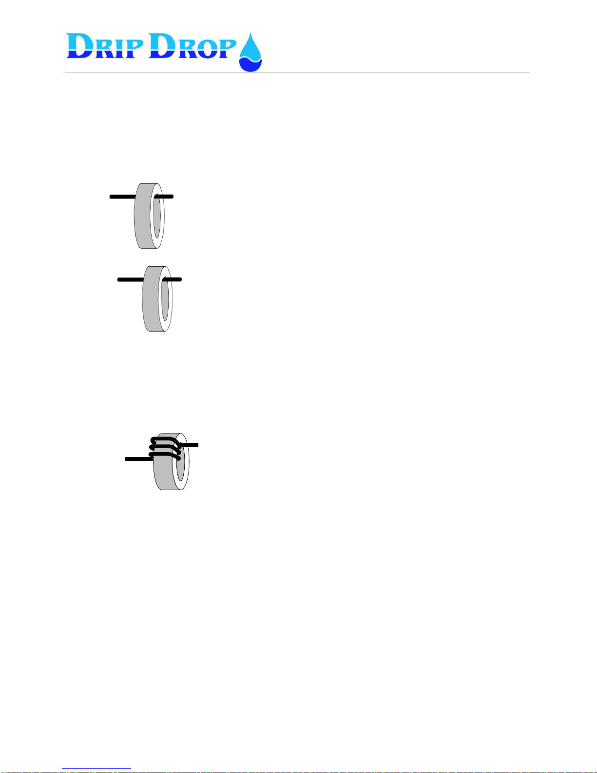
If a smaller than 50 amps. pump is measured, you will need to wind the phase power cable around the
transformer coil in order to increase accuracy, the as shown in the illustration below. Each turn of the
coil will lessen the rated current in to the transformer. See the following figure.
Once the correct number of turns around the coil is applied, you need to calculate the total
transformation factor.
You need to consider the transformer rate as well as the transformation rate for the winding around the
coil. You calculate the transformation factor the following way:
Figure 5.2.6 shows how one of the phases of the phases of the
pump is fed around the transformer coil.
For a 50/5 A transformer the following reduction in the measured input
current applies:
1 turn will give a 25/5 amps. rate. (for a pump up to 25 Amps.)
2 turns will give a 12,5/5 amps. rate. (for a pump up to 12,5 amps.)
3 turns will give a 6,25/5 amps. rate.(for a pump up to 6,25 amps.)
Example 1.
Using a 50/5 A transformer to measure a 35 Amps pump.
The transformer ratio is 10 .
Set the transformation factor in the PC 200 to 10.
Example 2.
Using a 100/5 A transformer to measure a 75 Amps pump.
The transformer ratio is 20 .
Set the transformation factor in the PC 200 to 20.
Page 24
MANUAL PC-200
Ver. 2.12.xx/10/22/2010-UK
Page 24 (61)
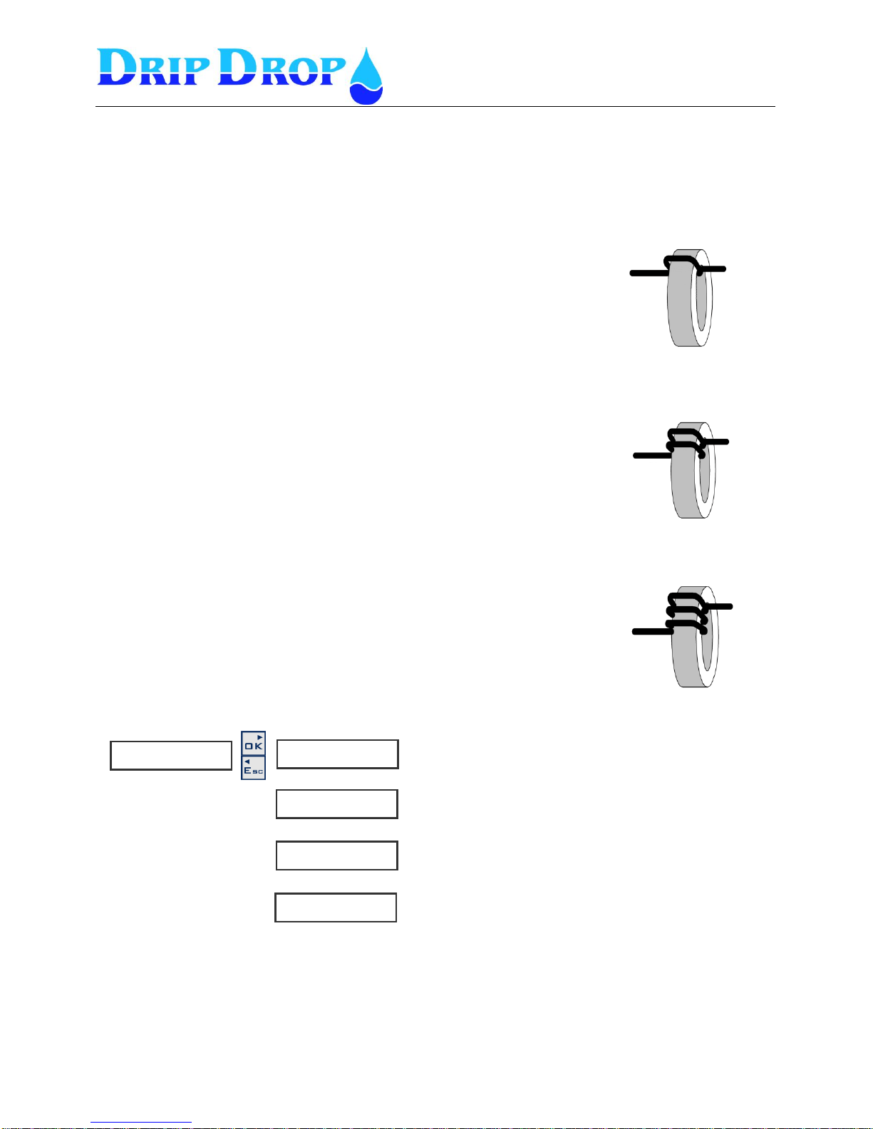
The factor F = transformer ratio / (n turns + 1)
You need to take the transformer rate for (example 10) and divide it by (the number of turns around
the coil +1).
Example 3.
Measuring a 20 Amps pump.
We use a 50/5 A. transformer where the transformer ratio is 10.
In order to increase tha accuracy of the measuring range we need to wind the powercable one
turn around the tranformer coil.
F = 10/(1+1) = 5
Set the transformation factor in the PC 200 to 5.
Example 4.
Measuring a 10 Amps pump.
We use a 50/5 A. transformer where the transformer ratio is 10.
In order to increase tha accuracy of the measuring range we need to wind the powercable 2
turns around the tranformer coil.
F = 10/(2+1) = 3.33
Set the transformation factor in the PC 200 to 3.33.
Example 5.
Measuring a 5 Amps pump.
We use a 50/5 A. transformer where the transformer ratio is 10.
In order to increase tha accuracy of the measuring range we need to wind the powercable 3
turns around the tranformer coil.
F = 10/(3+1) = 2.5
Set the transformation factor in the PC 200 to 2.5.
▼▲
C u r r e n t i n p u t s ►
◄
F u n c t i o n
◄◄ i n u s e
T r a n s f . I 1 f a c t .
◄◄ 1 . 0 0
T r a n s f . I 2 f a c t .
◄◄ 1 . 0 0
T r a n s f . I 3 f a c t .
◄◄ 1 . 0 0
▼▲
▼▲
Here the transformation factor value is set
Following choices ,in use and not in use
Here the transformation factor value is set
Here the transformation factor value is set
Page 25
MANUAL PC-200
Ver. 2.12.xx/10/22/2010-UK
Page 25 (61)
5.2.7 Temperature protection.
The unit has one input for term contacts in the motor winding, for each pump which if activated, will
stop the pump when the thermo contact is activated. When the term contacts function is used you have
the option to choose for the pump to stop and be able to start again once the term contact is
deactivated, or you can choose to block the pump which means that once the term contact is activated
and the pump stops, it will not be able to start again until the term contact alarm is manually
confirmed.
▼▲
T e m p . p r o t e c t o r s ►
◄
P 1 T e m p . p r o t . ►
◄◄
P 2 T e m p . p r o t . ►
◄◄
▼▲
F u n c t i o n
◄◄◄ i n u s e
S i g n a l t y p e
◄◄◄ N O
A l a r m f u n c t i o n
◄◄◄ Y e s
A l a r m d e l a y . [ s ]
◄◄◄ 1 . 0
B l o c k p u m p
◄◄◄ No
▼▲
▼▲
▼▲
▼▲
▼▲
Following choices, in use and
not in use
Following choies NO och NC
Here the delay is set in sec.
Following choices, Yes and No
Settings for P2 and P3 are
done as for P1
P 3 T e m p . p r o t . ►
◄◄
Following choices YES or NO
Page 26
MANUAL PC-200
Ver. 2.12.xx/10/22/2010-UK
Page 26 (61)
P u m p 2 ►
◄
P u m p 3 ►
◄
P u m p 1 ►
◄
T i m e / D e l a y s . ►
◄
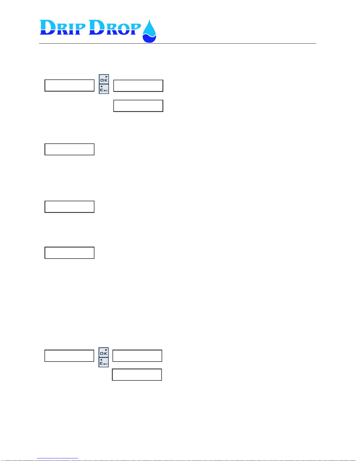
5.3 Pump settings
In the pump settings menu, all settings are made that directly deal with the pumps, start /stop levels,
alternation of the pumps, current settings a.s.o. These settings are made for each pump that is used, but
here only the settings for one pump (pump 1) are shown.
S t a r t l e v e l P 1
◄◄ 3 . 5 0
S t o p l e v e l P 1
◄◄ 0 . 5 0
A l t e r n a t i o n P 1
◄◄ Ja
M a x r u n t i m e 1 [ m i n ]
◄◄ 7 2 0
M i n b r e a k t i m e 1 [ s ]
◄◄ 1
R u n n i n g c o n f . ►
◄◄
C o n f . t i m e [ s ]
◄◄◄ 1 0
F u n c t i o n
◄◄◄ i n u s e
C u r r e n t s e t . ►
◄◄
B l o c k P u m p
◄◄◄ N o
S t a r t t i m e P 1 [ s ]
◄◄◄
U n d e r c u r r e n t ►
◄◄◄
1 - m i n [ A ]
◄◄◄◄ 0 . 0
D e l a y [ s ]
◄◄◄◄ 0
A l a r m f u n c t i o n
◄◄◄◄ No
O v e r c u r r e n t
◄◄◄
1 - m a x [ A ]
◄◄◄◄ 0 . 0
Del a y [ s ]
◄◄◄◄ 0
A l a r m f u n c t i o n
◄◄◄◄ No
▼▲
▼▲
▼▲
▼▲
▼▲
▼▲
▼▲
▼▲
▼▲
▼▲
▼▲
▼▲
Settings for P2 and P3 are
made the same as for P1.
▼▲
▼▲
▼▲
▼▲
Set start level
Set stop level
Following choices, Yes and No
Here the max running time
Is set in minutes
Here the break time before a
pump is allowed to startr is set
Here the time is set before
the answer is checked
Following choices, in use and
not in use
Following choices, in use and
not in use
Pump running time before
measuring starts
More in I/O settings
and Current settings
Setting of lowest current
before alarm
Timedelay before alarm is
sent
Setting of highest current
before alarm.
Following choises,Yes or No
Timedelay before alarm is
sent
Following choises,Yes or No
Page 27
MANUAL PC-200
Ver. 2.12.xx/10/22/2010-UK
Page 27 (61)
P u m p 1 ►
◄
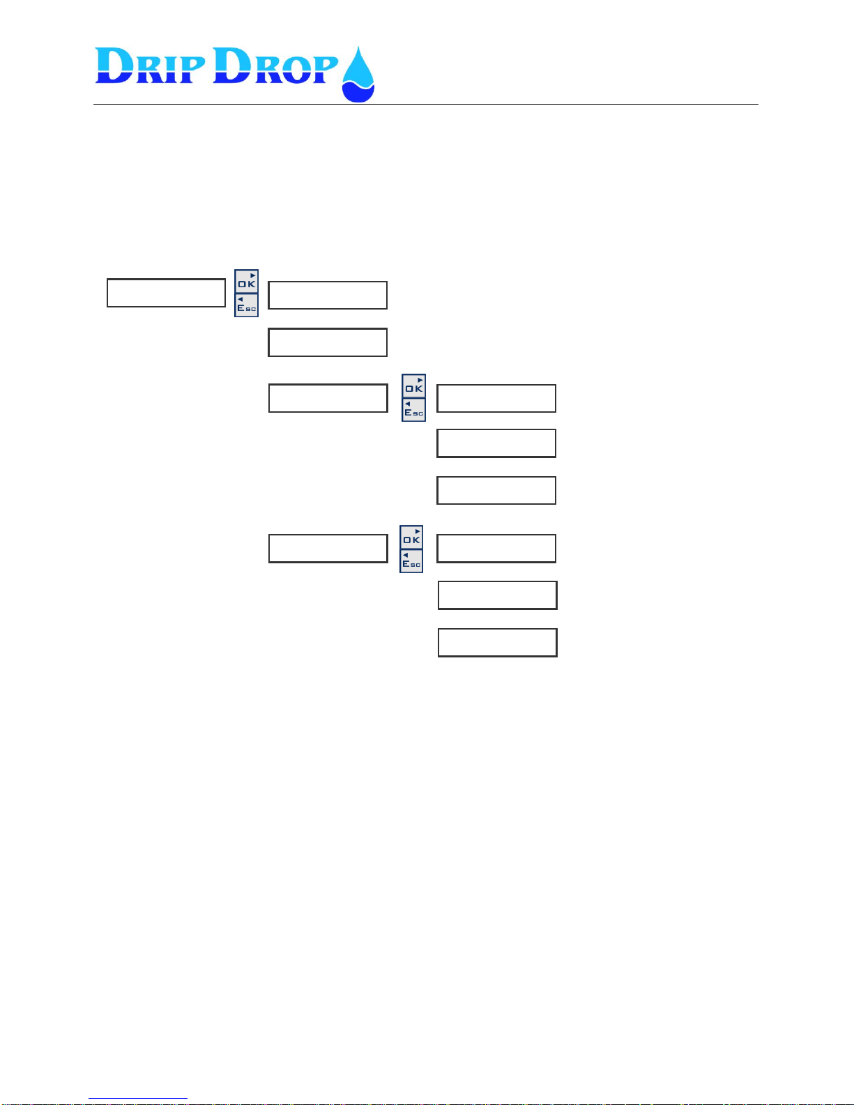
5.3.1 Start and stop levels
Start and stop levels – when the unit is used with analogue level sensor you will establish the start
and stop levels corresponding to each pump.
5.3.2 Alternation, running time and break time
Alternation – You can choose for each pump to be included in the alternation cycle or to work with
its own independent start and stop level.
Max running time - To avoid that a pumps runs too long time during a pumping cycle you can limit
the time the pump is allowed to run by setting a maximum time. When it is finished the pump will stop
and the next pump in the alternation cycle start. This time is set in factory to 720 seconds.
Minimum break time - To allow a pump to cool after running you can set a min.break time before the
pump can start again. This function can seem confusing because a pump will not start when you think
it should.
Running confirmation
If running confirmation is used you know if the pump is running, if no confirmation is received the
unit will send an alarm and try to start the next pump in the alternation cycle and eventually block the
pump. This function uses the measured pump current (Current input) with the inputs I 1 to 3 activated.
Running confirmation can only be made when current transformers are used.
NOTE see settingsMotor currents 5.3-4
S t a r t l e v e l P 1
◄◄ . 5 0
S t o p l e v e l P 1
◄◄ 0 . 5 0
A l t e r n a t i o n P 1
◄◄ Y e s
M a x r u n t i m e 1 [ m i n ]
◄◄ 7 2 0
M i n b r e a k t i m e P 1 [ s ]
◄◄ 1
R u n n i n g c o n f , ►
◄◄
C o n f . t i m e [ s ]
◄◄◄ 1 0
F u n c t i o n
◄◄◄ i n u s e
▼▲
▼▲
Here the start level is set
Following choices, Yes and No
Here the stop level is set
Here the max running time of the pump is set
Here the minimum break time before start is set
Following choices, In use and Not in use
Here the time is set before the confirmation is checked
Page 28
MANUAL PC-200
Ver. 2.12.xx/10/22/2010-UK
Page 28 (61)
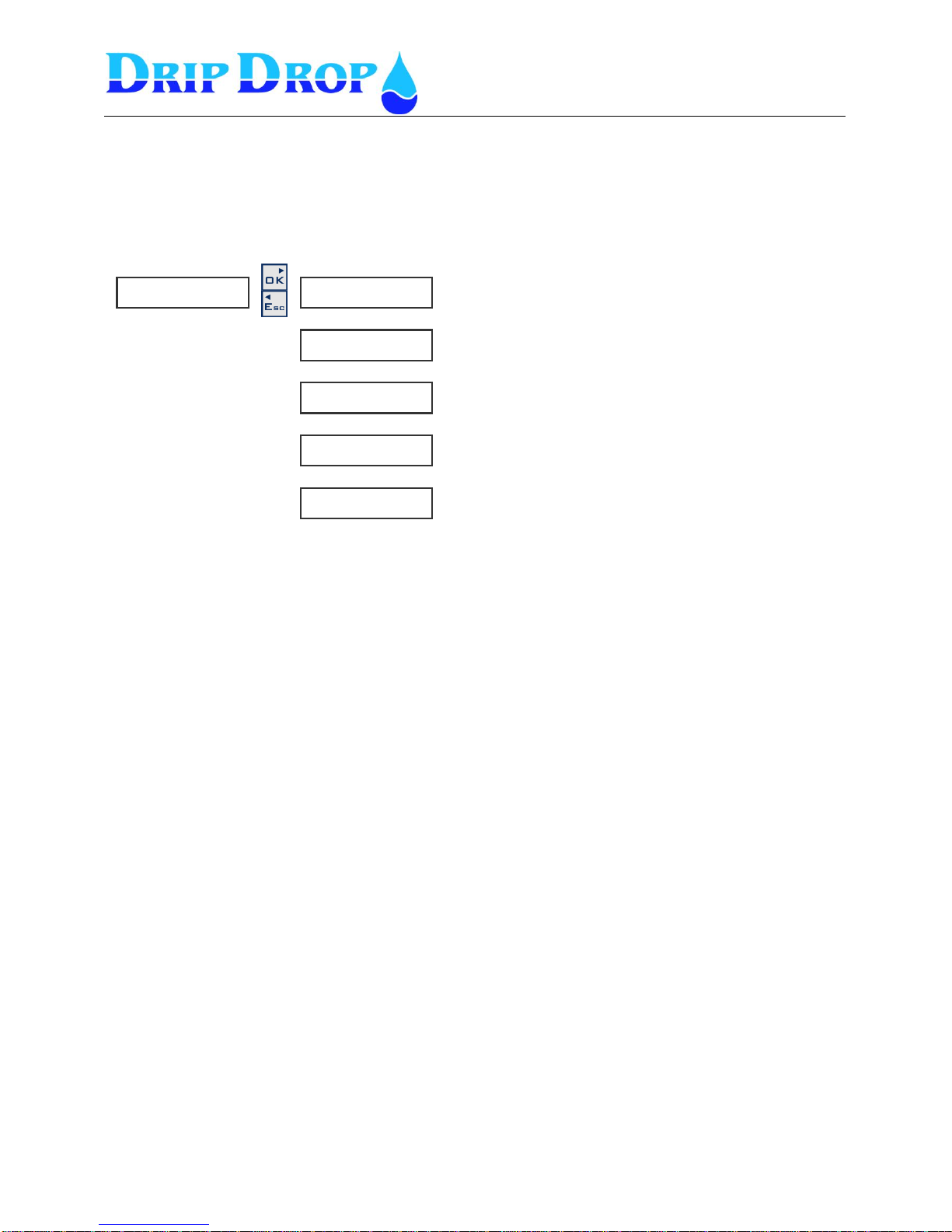
5.3.3 Setting of motor currents
Measuring of motor currents is used to check if the current is within the normal range for the pump
and to protect the pump from running dry, with clogged impeller or over currents.
The settings that must be done are explained below.
(This function will only appear in the menu if the pump current inputs are activated I1,I2 and I3.)
Block pumps – when an alarm for high or low current is activated, the pump is always stopped You
can choose if you want the pump to remain blocked until the alarm is confirmed or not to block the
pump and allow it to start next time it is activated in the alternation cycle without the alarm being
confirmed.
Pump- start time – to avoid that an alarm is activated during start of pumps there is a start delay to
allow the pumps to get into normal conditions for example when you use a soft start equipment.
Under current - the low current function is used to protect the pumps from working without fluid or
with a clogged impeller which stops the pump from pumping fluid but does not stop the impeller from
rotating
Over current - high current mostly occurs when the impeller can´t rotate freely and therefor increases
the current.
C u r r e n t s e t . ►
◄◄
B l o c k P u m p
◄◄◄ N o
S t a r t t i m e P 1 [ s ]
◄◄◄ 0
U n d e r c u r r e n t ►
◄◄◄
1 - m i n [ A ]
◄◄◄◄ 0 . 0
D e l a y . [ s ]
◄◄◄◄ 0
A l a r m f u n c t i o n
◄◄◄◄ No
O v e r c u r r e n t ►
◄◄◄
1 - m a x [ A ]
◄◄◄◄ 0 . 0
D e l a y . [ s ]
◄◄◄◄ 0
G i v e a n a l a r m
◄◄◄◄ No
Following choices, Yes or No
Running time of pump before measuring starts
▼▲
Highest current value before
alarm
Following choices, Yes or No
Lowest current value before
alarm
Time delay before alarm
▼▲
▼▲
▼▲
▼▲
▼▲
▼▲
▼▲
Time delay before alarm
Following choices, Yes or No
Page 29
MANUAL PC-200
Ver. 2.12.xx/10/22/2010-UK
Page 29 (61)
T i m e / D e l a y s . ►
◄
D e l a y o n . ( s ) ►
◄◄
D e l a y o f f ( s ) ►
◄◄
M i n . t i m e s t a r t s ( s )
◄◄ 5
M i n . t i m e s t o p ( s )
◄◄ 5
S w i t c h t i m e ( s )
◄◄ 2
5.3.4 Times / delay for pumps
In this menu you set the times and delays which are general for all pumps and different functions in
the pumping station.
Start delay– Signal delay for starts of pump when startlevel is reached, for ex when there is
turbulance on the surface of the pump pit.
Stop delay– Signal delay for stop of pump at stop level.
Min. Time starts* – Minimum time between start of pumps.
Min. Time stops **– Minimum time between stop of two pumps.
Switch time – Time delay between stop of pump with fault and start of next pump in the alternation
cycle
Backup running time Level switch operation – when only level switches are used to control de level
in the sump.
Min time starts Min. Time starts is the starts time delay between the first and the second pump when
the inflow is larger than one pumps capacity and there is need for a second pump to start.
Min time stopps Min. Time stops is the time delay between the stop of the first and the second pump
when two pumps are running.
▼▲
▼▲
▼▲
▼▲
Time delay before pump starts
Time delay before pump stops
Minimum time between
pump starts.
Minimum time between
Pump stop
Time between switching between pumps with automatic
alternation.
Page 30
MANUAL PC-200
Ver. 2.12.xx/10/22/2010-UK
Page 30 (61)
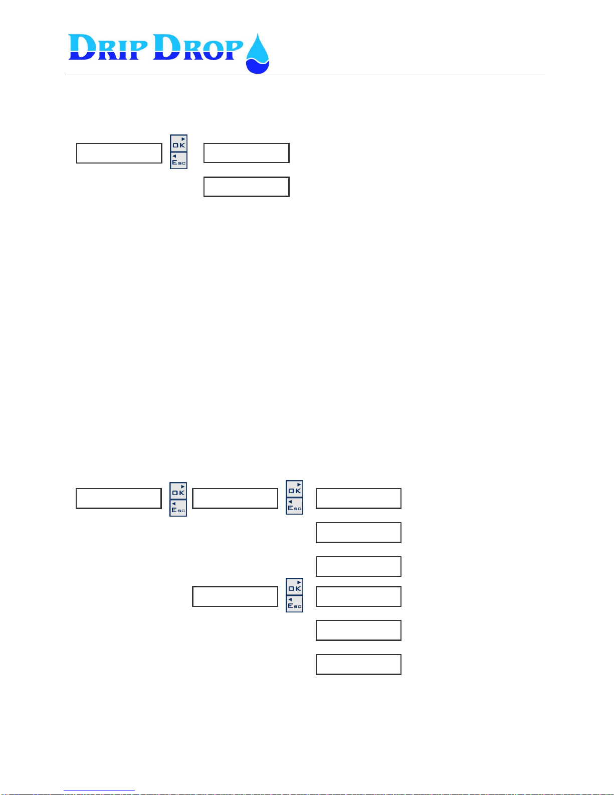
L o w l e v e l a l a r m ►
◄◄
H i g h l e v e l a l a r m ►
◄◄
A l t e r n a t i o n ►
◄
5.4 Station settings
All setting in this menu are general setting for the pump station .
5.4.1 Alternation type of pumps
The controller has two different ways of handling the alternation of the pumps:
1. Cyclic – witch means that the pumps alternate in a cyclic way, one after another. This means
that in the first cycle they start with pumps 1,2,3 and in the next cycle wirh pumps 2,3,1.
2. Running time – which means that the pump that has the lowest running time starts first. This
means that the pumps will have about the same running times.
The second setting decides if the next pump in the alternation cycle shall start when the working pump
has an fault or not.
- if you set ”alternation on fault” to Yes the next pump will start with a short time delay when the
working pump has a fault.
- if you set “alternation on fault ” to No the next pump will wait until the start level is reached before
it starts.
5.4.2 Level alarm settings (Low and high level alarms)
In this menu the level alarms for the level sensor are set. These alarms only show how the levels in the
station are, but control no pumps
A l a r m l e v e l s e t t . ►
◄
L o w l e v e l [ m ]
◄◄◄ 0 . 5 0
A l a r m f u n c t i o n
◄◄◄ Y e s
A l a r m d e l a y [ s ]
◄◄◄ 1
H i g h l e v e l
◄◄◄ 0 . 5 0
A l a r m f u n c t i o n
◄◄◄ J a
A l a r m d e l a y [ s ]
◄◄◄ 1
▼▲
▼▲
▼▲
▼▲
▼▲
▼▲
Here the level for low level
alarm is set
Here you set if the alarm
function shall be active or not
Here the time for alarm delay is
set
Here the level for high level
alarm is set
Here you set if the alarm
function shall be active or not
Here the time for alarm delay is
set
A l t e r n a t i o n t y p e ►
◄◄ c y c l i c
A l t e r n a t i o n t y p e ►
◄◄ c y c l i c
▼▲
Page 31
MANUAL PC-200
Ver. 2.12.xx/10/22/2010-UK
Page 31 (61)
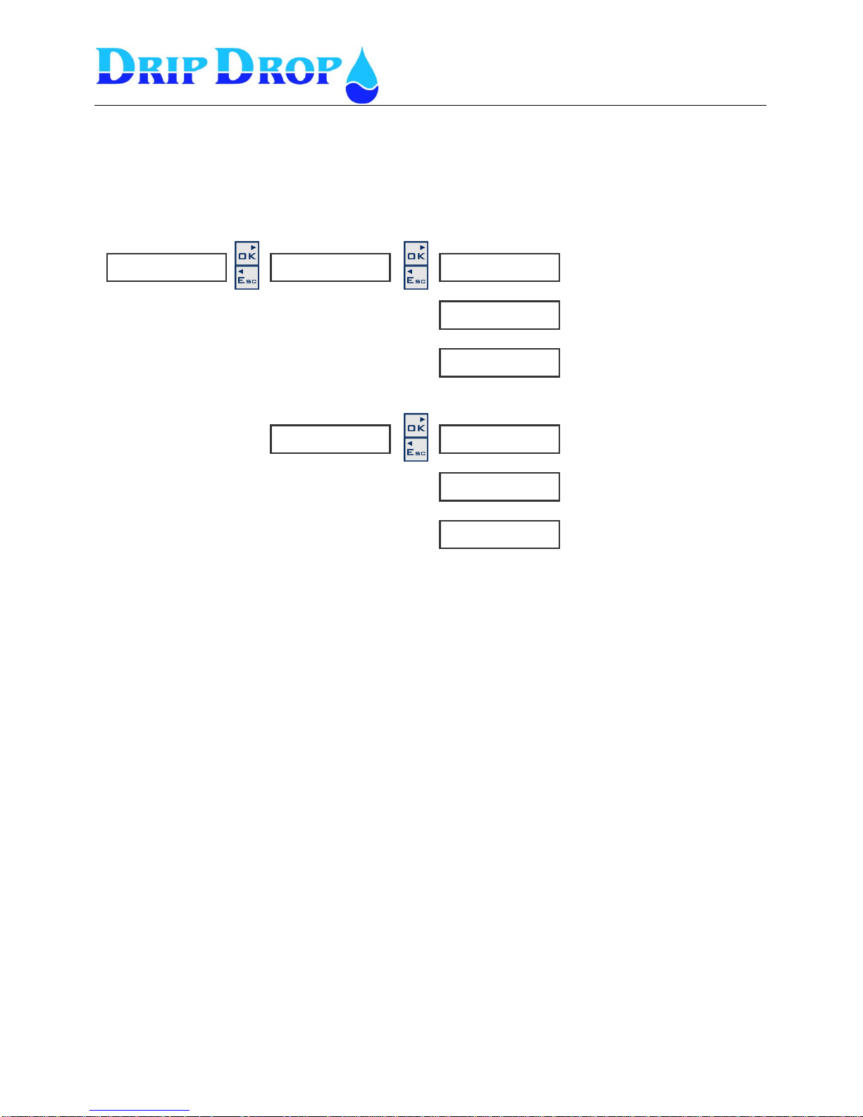
L o w s e t p o i n t ►
◄◄
H i g h s e t p o i n t ►
◄◄
5.4.3 AI 2 Setpoints, Analogue setpoints
For the Analogue input 2 which is a free choice/editable function adabtable to your specific needs
to measure analogue signals, pH, conductivity, flow etc.
For this signal you can set a high and a low set point which can be used to generate alarms for
example.
A I 2 S e t p o i n t s .►
◄
S e t p o i n t v a l u e
◄◄◄ 0 . 5 0
A l a r m f u n c t i o n
◄◄◄ N o
A l a r m d e l a y [ s ]
◄◄◄ 0 . 0
S e t p o i n t v a l u e
◄◄◄ 0 . 5 0
A l a r m f u n c t i o n
◄◄◄ N o
A l a r m d e l a y [ s ]
◄◄◄ 0 . 0
▼▲
▼▲
▼▲
▼▲
Here you set if the alarm
function shall be active or not
Here the setpoint for low alarm
is set
Here you set if the alarm
function shall be active or not
Here the time for alarm delay is
set
Here the setpoint for high
alarm is set
▼▲
Here the time for alarm delay is
set
▼▲
Page 32
MANUAL PC-200
Ver. 2.12.xx/10/22/2010-UK
Page 32 (61)
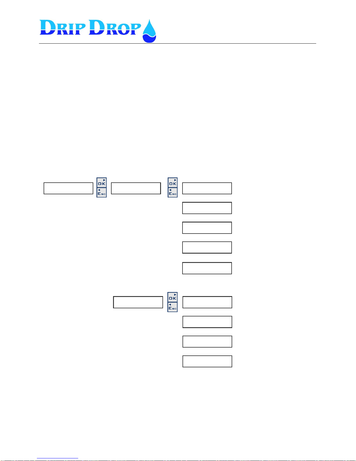
L e v e l t y p e ►
◄◄
T i m e r t y p e ►
◄◄
5.4.4 Mixer settings
In bigger stations a mixing device must be used to keep the pit clean. To install a non clogging mixer
device is recommended.
For the mixing function the controller has two separate forms of controlling the mixing device.
1. Start by level and stop by timer - during filling or emptying of the pit and stopping by a
timer. With this option you might set the function to start during filling phase (before pumping)
or the emptying phase (while pumping). The criteria of the frequency of the mixing is by
setting number of pumpcycles between mixing starts. The stopping of the mixing is made by
setting the running time by a timer.
2. Start and stop by timer – in this option you will set an idle time and a running time for the
mixing device. It will start at the elapsed idle time and keep running for the set operation time.
With this option the mixing will operate independent of the level in the pit. To avoid the
mixing while pumping (important at large flows) there is a function where you can block the
mixer while the pumps are ON.
M i x e r s e t t i n g s . .►
◄
T y p e
◄◄◄ e m t y i n g
S t a r t c y c l e s
◄◄◄ 0
S t a r t l e v e l [ [ m ]
◄◄◄ 0 . 0 0
S t a r t d e l a y [ s ]
◄◄◄ 0
R u n t i m e [ s ]
◄◄◄ 0
▼▲
▼▲
▼▲
▼▲
T y p e
◄◄◄ i n u s e
S t a r t a f t e r [ h ]
◄◄◄
R u n t i m e [ s ]
◄◄◄
B l o c k i f P . O n
◄◄◄ No
▼▲
▼▲
▼▲
▼▲
▼▲
Choice between emptying,
filling or None
Here the time for the start delay
is set
Here the running time of the
mixer is set
Here the startlevel of the mixer
is set
Choice between in use or not in
use
Here the idle time for the mixer
is set
Here the running time of the
mixer is set
Choice between blocking mixer
while pumps are on, Yes or No
Numbers of pump start cycles
before mixer starts
Page 33
MANUAL PC-200
Ver. 2.12.xx/10/22/2010-UK
Page 33 (61)
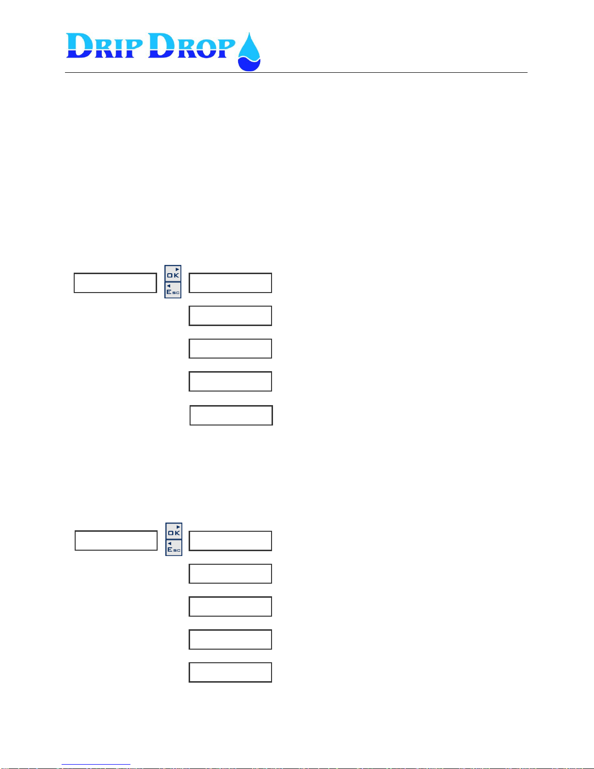
F u n c t i o n
◄◄ p e r s . a l .
F u n c t i o n
◄◄ i n t r u d e r
5.4.5 Attendance check (Person alarm or Intruder alarm)
Personalarm/ Intruder alarm- to create a signal an analoge input is used which is changed to a
digital signal by connecting an resistor in series with the analogr signal
Person alarm
For the function person alarm the input is activated via a signal cable that is connected to the light
switch in the station and starts an internal timer which after a set time activates a relay output. This
output can for example be connected to a horn or flashing light to inform the operator that the
operator time is finished and has to be prolonged. If this is not done a person alarm will be sent . To
avoid that this happens the light switch has to be turned off and on.
Intruder alarm
The function intruder alarm is activated via a signal cable that is connected to for ex. a magnetic
sensor in the door and starts an internal timer which is set to after a certain set time activates a relay.
This relay output can be connected to a horn or flashing light and send an intruder alarm. To avoid that
the alarm is sent a password must be entered on the keyboard.
A t t e n d a n c c h e c k .►
◄
s i g n a l t y p e
◄◄ N C / N O
C o n t . s i g n a l
◄◄ N o
L o g i n t i m e [ s ]
◄◄ 0
L o g o u t t i m e
◄◄ 0
S i g n a l t y p e
◄◄ N C / N O
C o n t i n o u s h o r n
◄◄ N o
V i s i t t i m e [ s ]
◄◄ 1 8 0 0
T i m e t o a l a r m .
◄◄◄ 1 8 0
▼▲
▼▲
▼▲
▼▲
▼▲
▼▲
▼▲
▼▲
▼▲
Choice between person alarm, intruder alarm and none
Choice between NC and NO
Choice between Yes and No
Personalarm
Intruder alarm
A t t e n d a n c e c h e c k ►
◄
Choice between person alarm, intruder alarm or none
Choice between NC and NO
Choice between Yes and No
The time needed for work in the station
Time before alarm is sent
Time before alarm is sent
when opening the door
Time before alarm is sent,
when the password is keyed in and door not closed
Page 34
MANUAL PC-200
Ver. 2.12.xx/10/22/2010-UK
Page 34 (61)
N o m i n a l [ V ] ( L - N)
◄ 2 3 0
F a i l b r e a k t i m e [ s ]
30
P h a s e r o t .►
◄
U n d e r v o l t a g e .►
◄
F u n c t i o n
◄◄ i n u s e
B l o c k p u m p
◄ No
F u n c t i o n
◄◄ i n u s e
B l o c k p u m p
◄◄ N o
S i g n a l d e l a y .
◄◄ 10
U n d e r v o l t a g r % .►
◄◄ 85
O v e r v o l t a g e ►
◄
F u n t i o n
◄◄ 2 3 0
B l o c k p u m p
◄◄ No
S i g n a l d e l a y
◄◄ 10
O v e r v o l t a g e
◄◄ 5%
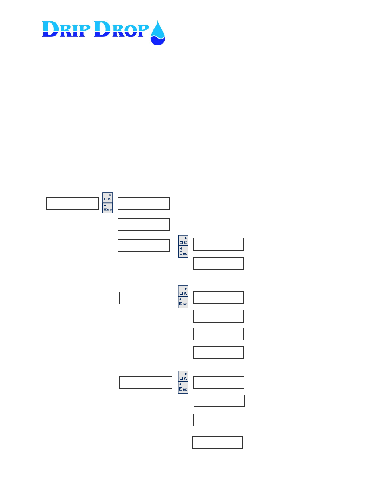
5.5 Voltage relay
If the phases are connected to the phase inputs of the unit the voltage, phase rotation, undervoltage,
overvoltage,unbalance and missing phases are checked. If the functions are activated the pumps can be
blocked if wanted and alarm given.
Nominal voltage-You will need to set the nominal voltage to be used in the installation, meaning the
real installation voltage i.e. 230, 400, 660 V. You must set the nominal voltage as the phase to
neutral value.
Failbreaktime – When the voltage relay detects a failure in the power supply, and the pumps are
blocked, the unit will hold the operation of the pumps on hold for a time – the fail break time – the
idea of this timer is to allow for the power supply to re-establish to stable conditions before the pumps
are put back to operation.
V o l t a g e r e l a y .►
▼▲
▼▲
▼▲
▼▲
▼▲
▼▲
▼▲
▼▲
▼▲
▼▲
▼▲
▼▲
Here the nominal incoming,
phase to neutral, voltage is
set.
This is the time the voltage is
allowed to be wrong.
Choice between in use or not
in use
Choice between Yes or No
Choice between in use or not in
use
Choice between Yes or No
Here the signal delay time is
set
Here the allowed undervoltage
in % is set, for.ex 85%
Choice between in use or not
in use
Choice between Yes or No
Here the signal delay time is
set
Here the allowed overvoltage in
% is set, for.ex 110%
Page 35
MANUAL PC-200
Ver. 2.12.xx/10/22/2010-UK
Page 35 (61)
U n b a l a n c e ►
◄
F u n c t i o n
◄◄ i n u s e
B l o c k p u m p
◄ No
S i g n a l d e l a y
◄◄ 10
U n b a l a n c e
◄◄ 7
M i s s i n g p h a s e ►
◄
F u n c t i o n
◄◄ in u s e
B l o c k p u m p
◄◄ No
S i g n a l d e l a y
◄◄ 10
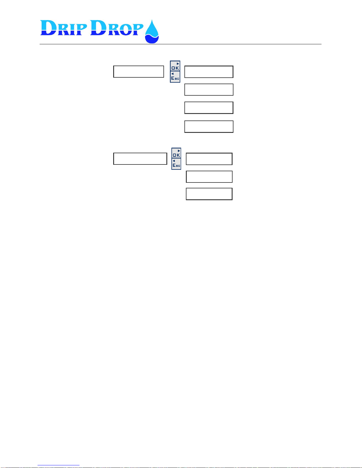
Voltage relay cont.
▼▲
▼▲
▼▲
▼▲
▼▲
▼▲
Choice between in use or not in
use
Choice between Yes or No
Here the signal delay time is set
Here the value in % is set for
the unbalance for ex. 7%
Choice between in use or not in
use
Choice between Yes or No
Here the signal delay time is set
▼▲
Page 36
MANUAL PC-200
Ver. 2.12.xx/10/22/2010-UK
Page 36 (61)
P a r i t y
◄◄◄ n o n e
S t o p b i t s
◄◄◄ 1
P r o t o c o l
◄◄◄ C o m l i
A d d r e s s
◄◄◄ 1
S t a t i o n I D
◄◄◄ 1
C o m m u n i c a t i o n ►
◄
C o n n e c t i o n . ►
◄◄
L i n k
◄◄◄ D i r e c t
C o n n e c t i o n . ►
◄◄
C o n n s e t t i n g s ►
◄◄
G S M s i g n . s t r e n g t ►
◄◄
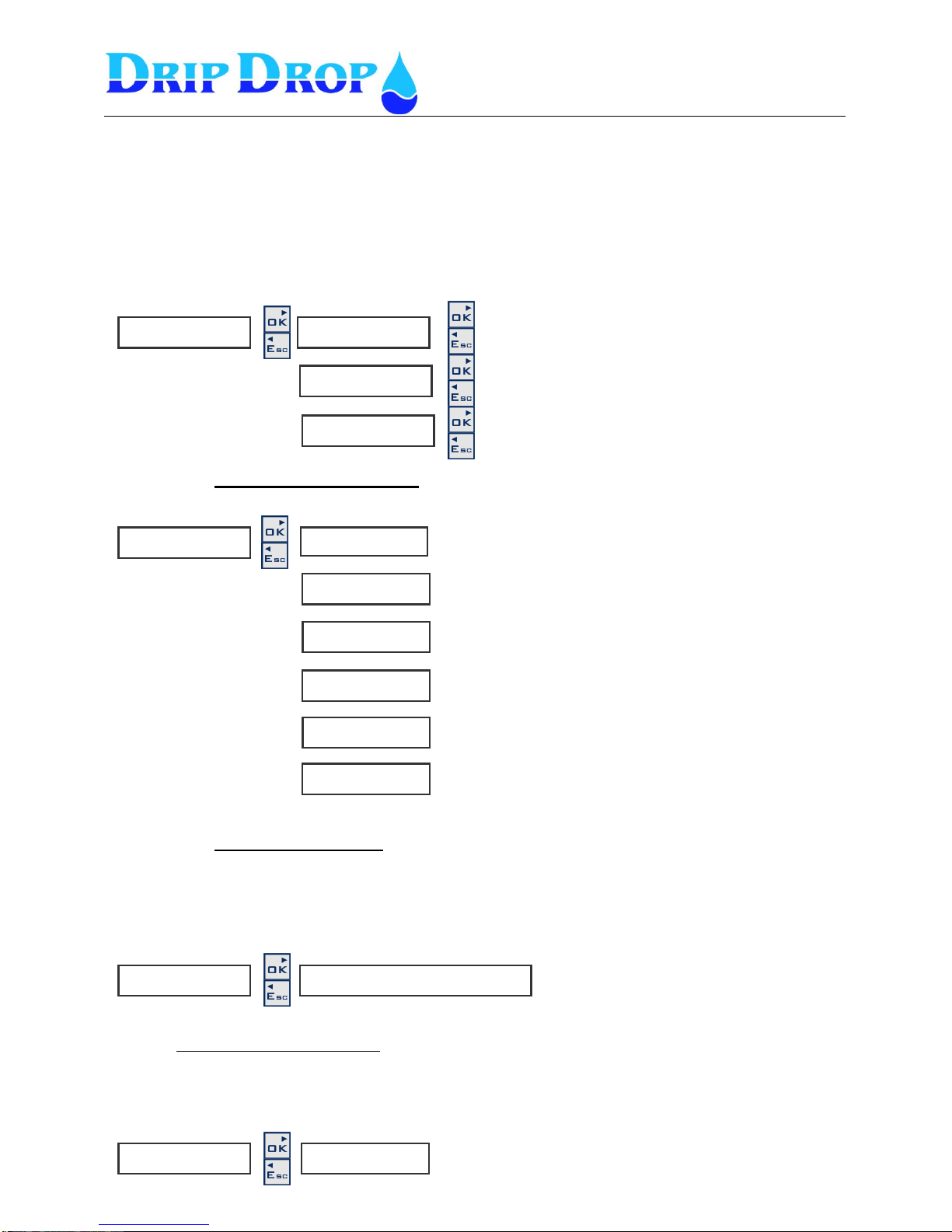
5.6 Miscellaneous
Under miscellaneous settings are the settings for communication, log-in, clock setting, default settings,
erase alarms, erase counters, erase runtimes and contrast control found.
5.6.1 Communication
Communication settings
Connection settings
Next step after the communication parameters is the connection settings . Which type of
communication equipment is to be used and what settings have to be made for the equipment
to work correctly. Communication alternatives are:
Direct (Fixed cable or radio)
The direct communicationen is the simplest way to communicate as communication is always
available.
C o m m . s e t t i n g s ►
◄◄
R a t e [ b p s ]
◄◄◄ 9 6 0 0
▼▲
▼▲
▼▲
▼▲
▼▲
The baud rate is between 1200 to 115000 baud.. Factory
setting is 9600
Here the number of stop bits is set
Choose between Modbus or Comli
Here the communication ID is set
Here the station ID is set
Here the parity is set. Choice between
None, even or odd
C o m m . s e t t i n g s . ►
◄◄
L i n k .
◄◄◄ D i r e c t D i a l u p G S M - S M S
Choices are, Direct, Dial up and GSM-SMS
Here theconnection settings and modem settings
are made
This window shows the GSM signal strength. This menu is
only shown if a GSM modem is selcted under connection
settings
Page 37
MANUAL PC-200
Ver. 2.12.xx/10/22/2010-UK
Page 37 (61)
H a y e s s t r i n g
◄◄◄ % r H 0 E 0 Q
M o d e m t y p e
◄◄◄ G S M
P i n c o d e
◄◄◄ 0 0 0 0
R e s e t p u l s e [ s ]
◄◄◄ 0
A l r m . R e s e n d n o .
◄◄◄ 2
R e t r y t i m e
◄◄◄ 0
C a l l a l a r m O F F
◄◄◄ N o
A n s w e r a f t e r
◄◄◄ 0
R e m o t e A C K
◄◄◄ N o
L i n k
◄◄◄ D i a l - u p
C o n n e c t i o n . ►
◄◄
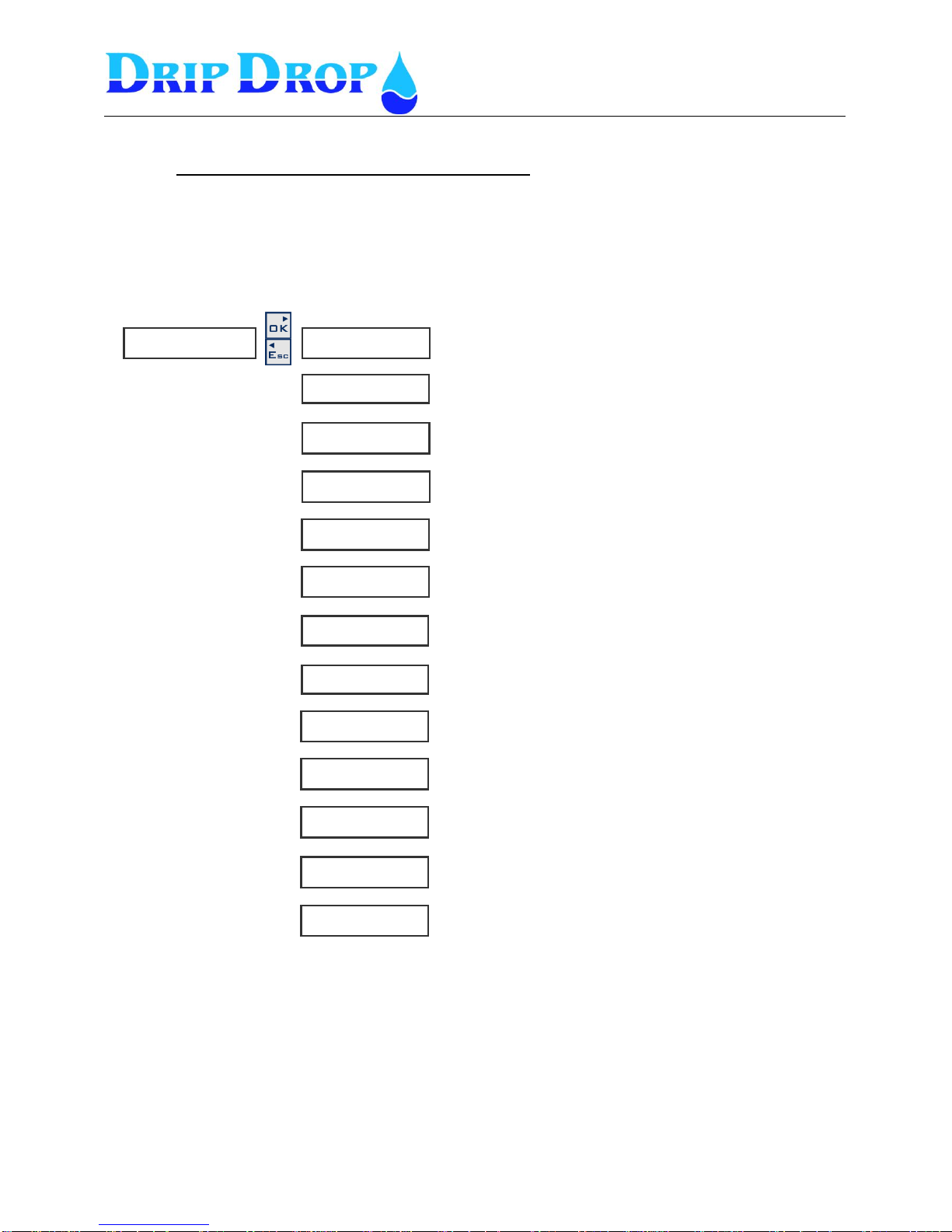
Dial-up (PSTN/Fixed telephony or GSM-modem)
Dial-up communication means that the connection between the units is made via a dial-up function.
This is done trough a telephone or GSM. This type of communication needs a modem for normal
telephone or a GSM modem. When modemtype is selected certain parameters must be set for the
modem to work correctly.
R e s e t m o d e [ m i n ]
◄◄◄ 0
▼▲
▼▲
▼▲
▼▲
▼▲
T e l n o . 1
◄◄◄ D i a l - up
C o n n e c t . s t r i n g
◄◄◄ 0
▼▲
▼▲
▼▲
▼▲
▼▲
▼▲
▼▲
Here you set the Hayes string. It is recommended to read the
manual of the modem.
PIN code is used only for GSM-modems . DripDrop
recommends that PIN code is not used.
Modem type, analogue modem Type PSTN or GSM modem
This is the telephone number of the modem connected to the
SCADA system.
Here the length of the reset pulse is set
Here the time between modem resets is set
This is an identification text that certain SCADA systems uses
Here the number of call signals before the station answers is
set
Here the number of retries is set.
Here the time between the retries isset.
In certain cases it is needed that the unit calls back when an
alarm goes OFF. Here this function is activated.
Here you set if the alarms can be remotly acknowledged or
not.
Here the communication type is set Dial-up
Page 38
MANUAL PC-200
Ver. 2.12.xx/10/22/2010-UK
Page 38 (61)
H a y e s s t r i n g
◄◄◄
P i n c o d e
◄◄◄ 0 0 0 0
T e l n o . 1
◄◄◄ 1 2 3 4 5 6
R e s e t p u l s e [ s ]
◄◄◄ 0
R e m o t e A C K
◄◄◄ N o
S t a t i o n n a m e
◄◄◄
L i n k
◄◄◄ G S M - S M S
C o n n e c t i o n . ►
◄◄
G S M s i g n . s t y r k a ►
◄◄
-
S g n : 5
GSM-SMS (SMS-text via GSM-modem)
These settings are used to send and receive SMS messages with a GSM telephone. You need a normal
SIM card with the SMS function activated. The PIN code of the SMS card can be activated or not.
The function allows up to three different mobile phone numbers to be activated. Depending on the
settings SMS messages can be sent to all phone numbers with a certain time delay.
GSM Signal strength
This is an status window which shows the actual signal strength in the GSM net if you selected to
Communicate via a GSM modem. If you selected any other type of communication this menu will no
apear
R e s e t m o d e m [ m i n ]
◄◄◄ 0
▼▲
▼▲
▼▲
▼▲
T e l n o . 2
◄◄◄ 1 2 3 4 5 6
▼▲
▼▲
▼▲
▼▲
T e l n o . 3
◄◄◄ 1 2 3 4 5 6
Here the length of the reset pulse is set
Here the time between modem resets is set
Here you set the Hayes string. It is recommended to read
the manual of the modem
PIN code is used only for GSM-modems . DripDrop
recommends that PIN code is not used.
This is telephone number 1 which can be set
This is telephone number 2 which can be set
This is telephone number 3 which can be set
Here the station name is set
Here you set if the alarms can be remotly acknowledged or
not.
Here the communication type is set to GSM/SMS
▼▲
Shows actual signal strength.
Page 39
MANUAL PC-200
Ver. 2.12.xx/10/22/2010-UK
Page 39 (61)
S y s . p a s s w o r d
◄ 0 0 0 0
C l o c k s e t t i n g ►
◄
C l o c k s e t t i n g
1 1 / 0 5 1 2 : 5 7 : 1 1
D e f a u l t s e t t i n g s
A r e y o u s u r e ?
D e f a u l t s e t t i n g s ►
◄
5.6.2 Trusted login
You have the option to set the unit to work with different log-in modes. The default factory setting is
that you need to log in whenever a change is made or an alarm is confirmed.
However, if preferred the unit can be set to always be logged-in for system privileges or to always be
logged-in for operator privileges.
5.6.3 Operator password
To change the passwords you use a combination of the four arrow keys .
5.6.4 System password
5.6.5 Clock setting
5.6.6 Default settings
Resets the controller to normally used pumpstation applications,
The prompt “Are you sure” is shown and must be confirmed with the OK key.
T r u s t e d l o g i n
◄ s y s t e m
O p p a s s w o r d
◄ Z Z Z Z
▼▲
▼▲
▼▲
▼▲
This menu is shown only if you are logged in with system code.
Choice between system, operator or none
To change to default settings press OK key
To change the system code press OK key and the cursor will be placed on the first
position which shall be changed, set new value, press OK to confirm. The cursor
moves to next position ▼▼▼▼
To change the clock setting press the OK key and the
cursor will be placed on the first position to be set. Set
value and press OK to confirm.The cursor is moved to next
position.
▼▲
To change the system code press OK key and the cursor will be placed on the first
position which shall be changed, set new value, press OK to confirm. The cursor
moves to next position.▲▲▲▲
Page 40
MANUAL PC-200
Ver. 2.12.xx/10/22/2010-UK
Page 40 (61)
E r a s e r u n t i m e s ►
◄
C o n t r a s t ►
◄
C o n t r a s t
L o g i n
P a s s w o r d
Z Z Z Z
5.6.7 Erase alarms
5.6.8 Erase counters
5.6.9 Erase runtimes
5.6.10 Contrast
5.7 Login / Logout
As an alternative to login when prompted so when making any changes of values or confirming
alarms, you can start your working session by login in, in this menu.
E r a s e c o u n t e r s . ►
◄
E r a s e c o u n t e r s
A r e y o u s u r e ?
E r a s e r u n t i m e s
A r e y o u s u r e ?
▼▲
▼▲
E r a s e a l a r m s ►
◄
E m p t y a l a r m l i s t ?
A r e y o u s u r e ?
▼▲
▼▲
To erase the alarmlist press the OK key
To erase the totaliser for the pulse inputs press the OK key.
To erase running times press OK key
To change the contrast, press ▲ for increasing contrast
and▼for decreasing contrast. Press Ok to confirm.
Login by introducing the correct password and press the OK
key
Page 41
MANUAL PC-200
Ver. 2.12.xx/10/22/2010-UK
Page 41 (61)
P 1 n o c o m m a n d
a v a i l a b l e
S t a r t P 2
S t o p P 3
S t a r t l e v e l P 1
3 . 0 0
S t o p l e v e l P 1
◄ 0 . 5 0
S t a r t l e v e l P 2
◄ 3 . 5 0
S t o p l e v e l P 2
◄ 0 . 6 0
S t a r t l e v e l P 3
◄ 5 . 6 0
S t o p l e v e l P 3
◄ 0 . 5 0
L o w l e v e l [ m ]
◄ 0 . 4 0
H i g h l e v e l [ m ]
◄ 6 . 0 0
6 Level settings
For an easier access to the set the different levels there is a specific level settings menu where will set
the start and stop level for the pumps as well as low and high levels alarms.
7 Manual start and stop of pumps
When the pumps are in Auto mode they can be started manually from the PC 200, this is the menu
where you can start and stop pumps manually.
You will be able to start and stop all used pumps, if they don’t have any active condition that prevents
them from starting, alarms low level etc.
M a n u a l c o n t r o l ►
▼▲
▼▲
L e v e l s e t t i n g s ►
▼▲
▼▲
▼▲
▼▲
▼▲
▼▲
▼▲
The pumps can only be started if the actual level is between
the start and stop level settings.
The pumps are started and stopped by pressing the OK key.
Here you set the start och stop levels for the pumps and the
level for low and high alarm
Page 42
MANUAL PC-200
Ver. 2.12.xx/10/22/2010-UK
Page 42 (61)
* A c t i v e a l a r m s
A l l a l a r m s
* N o t A C K a l a r m s
A l l a l a r m s
P 1 M o t o r p r o t e c t .
▼ A c t i v e A c k n ?
P 1 M o t o r p r o t e c t .
A c k n o w l e d g e ?
*Ac t i v e a l a r m s
A l l a l a r m s
* N o n e w a l a r m s
A l l a l a r m s
* N o n e w a l a r m s
A l l a l a r m s
* N o t A C K a l a r m s
A l l a l a r m s
8 Alarm status
The pumpcontroller has the capacity to generate a large number of different alarms for the pumps, the
station and internal alarms. Each of these alarms generates an information window when activated,
with information about which alarm it is. At the same time a LED with blinking light is activated until
the alarm is acknowledged.
Red blinking light means a new alarm which is not acknowledged.
Fixed red light means an alarm which has been acknowkedged but still is active.
8.1 Alarm handling
When you want to look at the alarms or acknowledge them you need to enter the alarm status menu,
depending on the status of the alarms, Not Acknowledged alarms (new alarms), Active alarms or No
new alarms you will enter one of the three submenues as below. To enter and see all alarms (alarm
history) you press the ▼ key, and the OK key.
8.2 New alarms
When there is a new alarm activated, you will by default enter the Not Ack alarms section of the alarm
handling. Here you can easily acknowledge all new alarms by using the OK key. If you choose not to
acknowledge but only to look at all new alarms you will go up and down in the not ack alarm list with
the ▲▼ keys.
Once all alarms have been acknowledged you will automatically get into the Active alarms
display.
If the alarms are no longer active, when you have acknowledged them you will
enter the No new alarms menu when all alarms have been acknowledged.
A l a r m S t a t u s ►
When there are new alarms, you will enter the Not
ACK alarms menu by default, where you can
acknowledge all alarms.
When there are no alarms to acknowledge you will
enter the Active alarms list, where you can see all
active alarms.
When there are no active alarms present you will enter
the No new alarms menu.
A l a r m S t a t u s ►
Page 43
MANUAL PC-200
Ver. 2.12.xx/10/22/2010-UK
Page 43 (61)
A c t i v e a l a r m s
* A l l a l a r m s
P 1 N o t i n a u t o
▼ A c t i v e A c k n ?
P 1 M o t o r p r o t e c t .
◄ O n : 1 1 / 1 1 0 7 : 5 7
P 1 M o t o r p r o t e c t .
◄ O f f : 0 0 / 0 0 0 0 : 0 0
√ P 2 M o t o r p r o t e c t .
♦ A c t i v e
P 1 M o t o r p r o t e c t .
◄ A c k : 2 5 / 1 0 1 0 : 5 5
√ P 1 M o t o r p r o t e c t .
♦ N o t A c t i v e
√ P 2 M o t o r p r o t e c t .
▲ A c t i v e
*Ac t i v e a l a r m s
A l l a l a r m s
√ P 1 M o t o r p r o t e c t .
▼ A c t i v e
√ P 2 M o t o r p r o t e c t .
▲ A c t i v e
8.3 Active alarms
When there are new alarms to acknowledge you will by default enter the Active alarms section in the
alarm handling. Here you can see all active alarms one by one using the OK key, once you have gone
through all active alarms you will return to the Active alarms menu.
8.4 All Alarms
In the all alarms list you can look at all registered alarm events, active, not active , acknowledged and
not acknowledged alarms.
When you enter all alarms you enter a list of all registered alarmevents, where you can se all alarms
one by one. The ▼ Arrow in the display means that you are at the top of the list and that there are
older alarms to watch in the list. A ▲ arrow means that you are at the bottom of the list and that all
other alarms in the list are newer than this alarm. ▲▼ arrows means that you have both newer and
older alarms in the list than the one you are looking at. The √ sign in front of the alarm means that the
alarm is acknowledged, and an not acknowledged alarm still has the acknowledge prompt attached to
it.
If you press the OK key when looking at an alarm you will access the information of the time when the
alarm occurred, when it went unactive and when it was acknowledged. The alarm that shows first in
the list is the latest occurred alarm.
Alarm history
In the alarm list for active and all alarms totally max. 8 alarms can be stored. When the alarm list is
full the oldest disapears.
▼▲
▼▲
▼▲
▼▲
▼▲
A l a r m S t a t u s ►
Page 44
MANUAL PC-200
Ver. 2.12.xx/10/22/2010-UK
Page 44 (61)
9 SMS-functions - use of mobil phone
With the function to send SMS activated you can send SMS messages , acknowledge alarms and
receive information from the PC 200 about the alarms and values about pumps and if they are running
or not
9.1 Alarm by SMS messages
When an alarm is generated in the PC-200, a text message is sent by the connected GSM modem to the
established phone list. The modem will send an SMS text alarm to the first mobile phone in the
telephone number list (maximum 3 numbers), the message will have the following format:
For the settings on how to send the SMS messages see chapter 5.6.1.
9.2 Remote confirmation of the alarms
Once you have received an alarm message on your phone and you have activated the remote
confirmation function, you will confirm the alarm remotely by returning the same alarm text to the
PC-200. Depending on the mobile phone there are different ways of doing this. But the important is to
send back the same message that you have recieved on the phone.
Once the PC-200 receive your return SMS message, the blinking Alarm lamp will stop blinking as an
indication of that the alarm is confirmed.
When receiving an alarm sent by the PC 200, return the same message to the PC 200, and the alarm will
be confirmed remotely
(005)
Main Station
Alarm pump 1
Over current
(1)
In the mobile phone you will se the following about the alarms:
-The internal alarm number
-Pumpstation name
-That it an alarm from pump number 1
-Alarm name.
(005)
Main Station
Alarm pump 1
Over current
(1)
Page 45
MANUAL PC-200
Ver. 2.12.xx/10/22/2010-UK
Page 45 (61)
9.3 To ask questions via SMS texts
In addition to receiving SMS-alarms from the unit you can send questions for further detailed
information as shown below.
1. Information about active alarms
2. Information about pump status, time and number of starts
3. Information about actual values in the station , level and running or stopped pumps.
1. Information group (Alarms)
2. Information group (Status)
3. Informationgroup (Station data)
Get a
Alarms occured:
1. Alarm pump 1
Over current
2. Alarm pump 2
NOT in AUTO
To receive information about active
alarms –
Send following message
Received message is an answer
with a list of active alarms…
Get s
Pump status:
P1 No of starts: 10
P1 Operation time: 5.25
P2 o of starts: 9
P2 Operation time: 5.10
To receive information about the
pump status-Send followung message
Received message of the status of
the pumps, how many starts of the
pumps and operation time today since
00,00 hrs.
Get d
Actual values:
Level (m):
Q out (l/s):
P1= OFF
P2 = ON
P3 = OFF
To receive information about the
actual values –
Send following message
Received message with actual
level, outflow and if pumps are
running or not.
Page 46
MANUAL PC-200
Ver. 2.12.xx/10/22/2010-UK
Page 46 (61)
10 I/O-list, Signal table
Upprättad av
Prepared by
Datum - Date
Dokument Nr
Document No.
Rev
Contaktperson
yy-mm-dd
A
Referens / Object:
Tillhör referens - File/Reference
Company / Station name
PC-200 - Programversion: 2.12.1
I/O no
Signal type
Signal function
Notes
DOI
17//18
Start/Stopp P1
NO
DO2
19/20
Start/Stopp P2
NO
DO3
21/22
Start/Stopp P3
NO
DO4
23/24
Mixer
NO
DO5
25/26
Not acknowledged alarms
NC
DO6
27
Attendance alarm
NO
DO7
28
Modem control
NO
.
DI 1
29
P1 Not in Auto
NC
Most times NC
DI 2
30
P1 Motor protector
NO
DI 3
31
P2 Not in Auto o
NC
Most times NC
DI 4
32
P2 Motor protector
NO
DI 5
33
P3 Not in Auto
NC
Most times NC
D I6
34
P3 Motor protector
NO
DI 7
35
Low level
NO
DI 8
36
High level / Overflow
NO
DI 9
8
External blocking / Overflow
NO
DI 10
12
Attendance check
NO
L1 1 Voltage phase L1
L2 2 Voltage phase L2
L3
3
Voltage phase L3
N 4 Neutral for voltage and current
I1 5 Current input P1
I2 6 Current input P2
I3 7 Current input P3
T1 9 P1 Temp. protection
NC
T2
10
P3 Temp. protection
NC
T3
11
P3 Temp. protection
NC
CI
37
Pulse input (Counter)
--
AI 1
13
Analogue In (0/4-20 mA)
Analogue input
AI2
2
Analogue In (0/4-20 mA)
Free choice Analogue input
Page 47
MANUAL PC-200
Ver. 2.12.xx/10/22/2010-UK
Page 47 (61)
11 Configuration table
Application type
No of pumps
Max No of working pumps
Emptying/filling
Advanced mode
Digital inputs
No
Type
Function
Signal
Type
Alarm
function
Delay
DI1
P1 Not in Auto
DI 2
P1 Motor protector
DI 3
P2 Not in Auto
DI 4
P2 Motor protector
DI 5
P3 Not in Auto
DI 6
P3 Motor protector
DI 7
Low float
DI 8
High float / Overflow
DI 9
Ext Blocking / Overflow
DI 10
Attendance check
Digital outputs Signal
DO 1
Start/Stop P1
DO 2
Start/Stop P2
DO 3
Start/Stop P3
DO 4
Mixer DO 5
Not ack. Alarms
DO 6
Attendance Alarm
DO 7
Modem reset
Counters
1 Puls
Max delay.
CI1
Pulse inputs( Counter)
Analogue inputs
Signal
Range
0/4 mA
Range
20 mA
AI 1
Level Sensor
AI 2
Free choice
I 1
P1 Motor current
I 2
P2 Motor current
I 3
P3 Motor current
N
Neutral for Current and Voltage
L 1
Voltage phase L 1
L 2
Voltage phase L 2
L 3
Voltage phase L 3
Page 48
MANUAL PC-200
Ver. 2.12.xx/10/22/2010-UK
Page 48 (61)
Pump settings
Pump 1
Pump 2
Pump 3
Day levels
Start[m]:
Stop[m]:
Alternation
Yes / No
Max. Runtime
[min]:
Min. Breaktime
[sek]:
Running confirmation
Function
Conf. time [s]
Current setting
Block pump
Under current
I-min[A]
Alarm delay [s]
Alarm function
Over current
I-max[A]
Alarm delay [s]
Alarm function
Times / Delays
Start delay [s]:
Stop delay :[s]
Min.- time starts[s]:
Min.- time stop [s] :
Switching time [s]:
Station settings
Alternation
Type:
Alt. on fail:
Alarm levels
High level alarm
Set point[m] :
Signal delay [s]:
Low level alarm
Set point[m] :
Signal delay;
Mixer Level type
Emptying/Filling
Start cycles
Start level
Start delay[s]
:Runtime[s]
Timer type
Start after[h]:
Runtime [Min]:
Block if Pump is running
Page 49
MANUAL PC-200
Ver. 2.12.xx/10/22/2010-UK
Page 49 (61)
Miscellaneous
Operator password
▲▲▲▲
System password
▼▼▼▼
Settings RS 232
Communication sett.
Baud rate:
Parityt:
Stop bits:
Protocol:
Communication ID:
Station ID:
Conections.
Link:
Modem reset[m]:
Reset pulse[s]:
Hayes:
PIN code:
Tel no1:
Tel no2:
Tel no3:
Stn:(Stationsnamn):
Remote ackn. Ja/Nej
Ackn. time SMS[x10s]:
*Idc: (Stationsnamn)
*Answer after:
*Alarm resend no:
*Retry time[s]:
*Call alarm OFF
+
Page 50
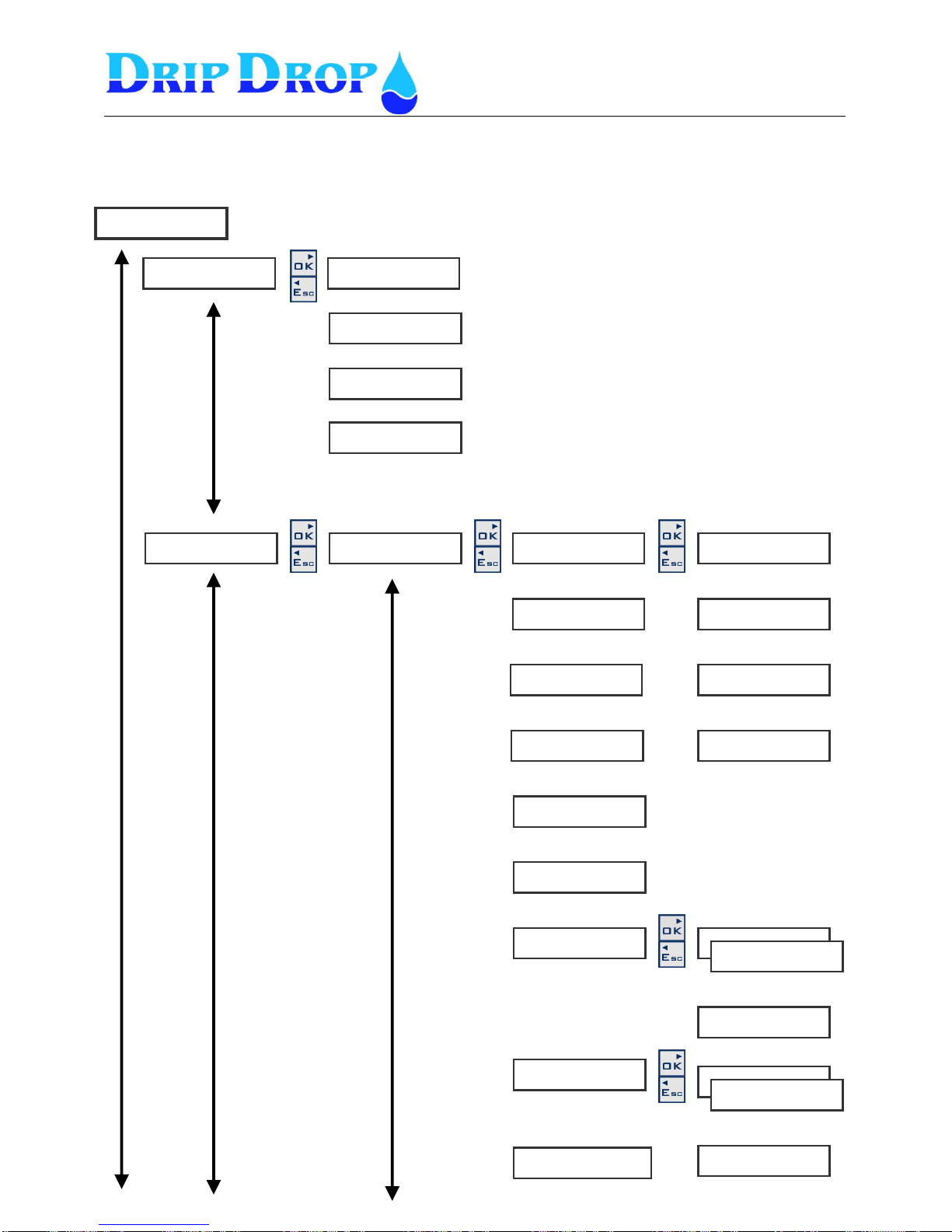
MANUAL PC-200
Ver. 2.12.xx/10/22/2010-UK
Page 50 (61)
N u m b e r o f p u m p s
◄ 3
A d v a n c e d m o d e
◄ Y e s
M a x . N o o f p u m p s
◄ 2
F u n c t i o n
◄ E m p t y i n g
12 Menu structure – Settings
▼▲
▼▲
A p p l i c a t i o n ►
▼▲
I / O s e t t i n g s ►
D i g i t a l I n p u t s ►
◄
1 . P 1 N o t i n A u t o ►
◄◄
F u n c t i o n
◄◄◄ i n u s e
2 . P 1 M o t o r p r o t . ►
◄◄
3 . 2 N o t i n A u t o ►
◄◄
4 . P 2 M o t o r p r o t . ►
◄◄
▼▲
▼▲
▼▲
▼▲
S i g n a l t y p e
◄◄◄ N C
A l a r m f u n c t i o n
◄ ◄◄ N o
A l a r m d e l a y [ s ]
◄◄◄ 1 . 0
▼▲
▼▲
5 . P 3 N o t i n A u t o ►
◄◄
▼▲
▼▲
6 . P 3 M o t o r p r o t . ►
◄◄
7 . L o w f l o a t ►
◄◄
S t o p p u m p s
Y e s
▼▲
▼▲
▼▲
8 . H i g h f l o a t ►
◄◄
S t a r t p u m p s
No
▼▲
9 . B l o c k / O v f . ►
◄◄
▼▲
S y s t e m s e t t i n g s ►
Page 51
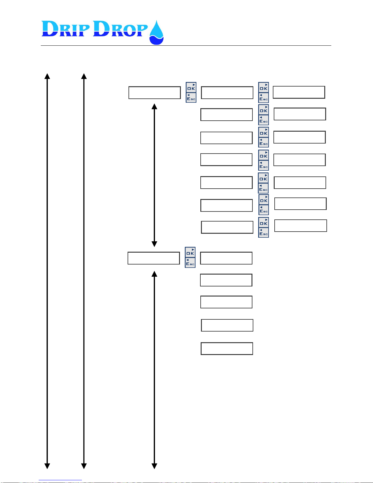
MANUAL PC-200
Ver. 2.12.xx/10/22/2010-UK
Page 51 (61)
D i g i t a l O u t ►
◄
1 . P 1 S t a r t / S t o p ►
◄◄
2 . P 2 S t a r t / S t o p ►
◄◄
3 . P 3 S t a r t / S t o p ►
◄◄
4 . M i x e r f u n c t i o n ►
◄◄
▼▲
▼▲
▼▲
5 . N o t a c k n . a l a r m s ►
◄◄
▼▲
▼▲
6 . A t t e n d a n c e ►
◄◄
7 . M o d e m c o n t o l ►
◄◄
▼▲
P u l s e c o u n t e r ►
◄◄
F u n c t i o n
◄◄ F l o w m e t e r
F l o w u n i t
◄◄ m 3 / h
P u l s e u n i t
◄◄ m3
1 P u l s e [ ]
◄◄
▼▲
▼▲
▼▲
M a x . d e l a y [ s ]
◄◄ 5
▼▲
S i g n a l t y p e
◄◄◄ NO
S i g n a l t y p e
◄◄◄ NO
S i g n a l t y p e
◄◄◄ NO
S i g n a l t y p e
◄◄◄ NO
S i g n a l t y p e
◄◄◄ NO
S i g n a l t y p e
◄◄◄ NO
S i g n a l t y p e
◄◄◄ NO
System settings
I/O settings cont.
Page 52
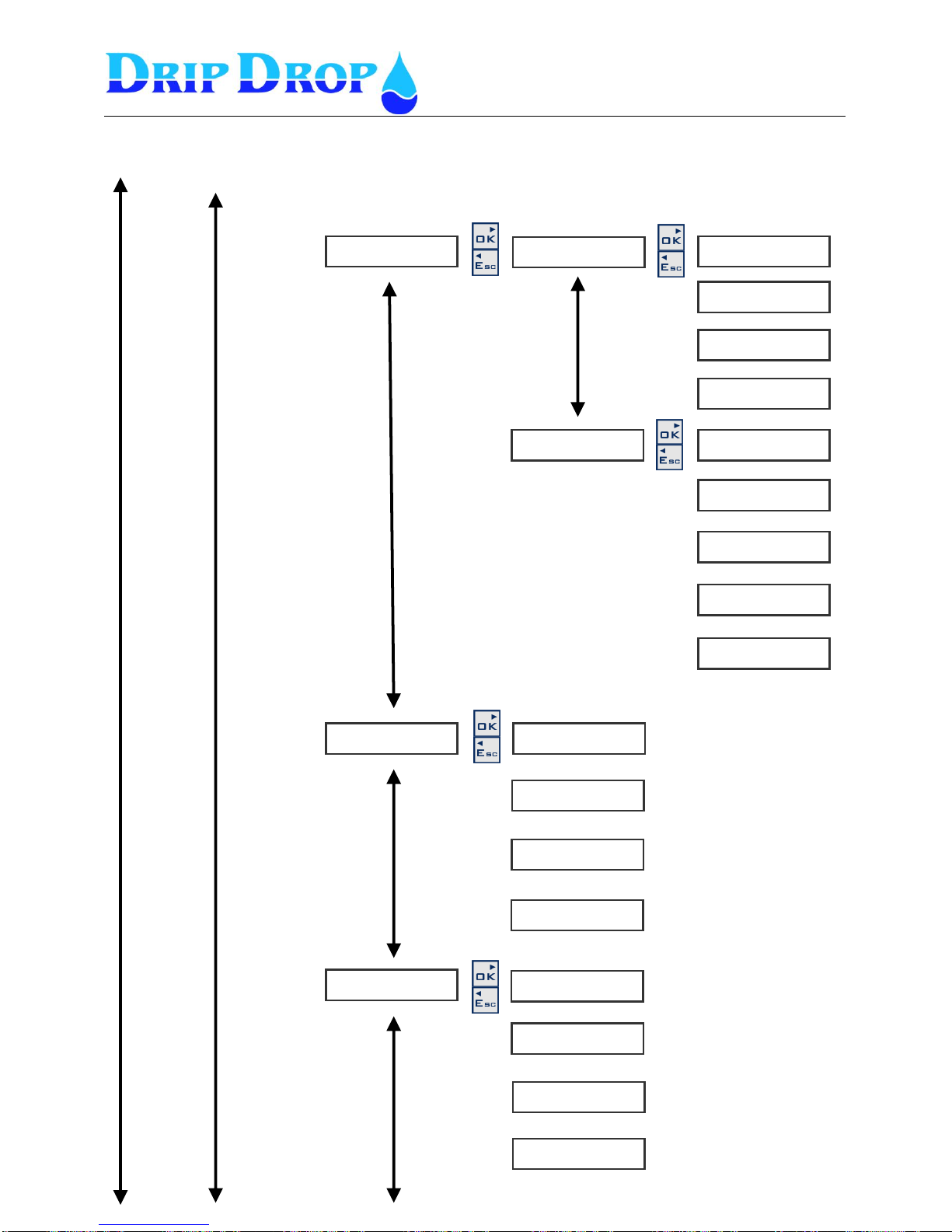
MANUAL PC-200
Ver. 2.12.xx/10/22/2010-UK
Page 52 (61)
▼▲
1 . L e v e l s e n s o r ►
◄◄
2 . F r e e c h o i c e ►
◄◄
S i g n a l t y p e
◄◄◄ 4 - 2 0 m A
A I 1 < - > 2 0 m A
◄◄◄ 5 . 0 0
A I 1 < - > 0 / 4 m A
◄◄◄ 0 . 0 0
▼▲
▼▲
S i g n a l t y p e
◄◄◄ 4 - 2 0 m A
A I 1 < - > 2 0 m A
◄◄◄ 5 . 0 0
A I 2 < - > 0 / 4 m A
◄◄◄ 0 . 0 0
▼▲
▼▲
U n i t f o r A I 2
◄◄◄ %
▼▲
▼▲
V o l t a g e i n p u t s ►
◄
F u n c t i o n
◄◄ i n u s e
T r a n s f . U 1 r a t e
◄◄ 1 . 0 0
T r a n s f . U 2 r a t e
◄◄ 1 . 0 0
T r a n s f . U 3 r a t e
◄◄ 1 . 0 0
▼▲
▼▲
▼▲
C u r r e n t i n p u t s ►
◄
F u n c t i o n
◄◄ i n u s e
T r a n s f . I 1 r a t e
◄◄ 1 . 0 0
T r a n s f . I 2 r a t e
◄◄ 1 . 0 0
T r a n s f . I 3 r a t e .
◄◄ 1 . 0 0
▼▲
▼▲
T e x t f o r A I 2
◄◄◄ C h o i c e
U n i t f o r A I 1
◄◄◄ %
Systemsettings
I/O settings cont.
A n a l o g u e i n p u t s ►
◄
▼▲
Page 53
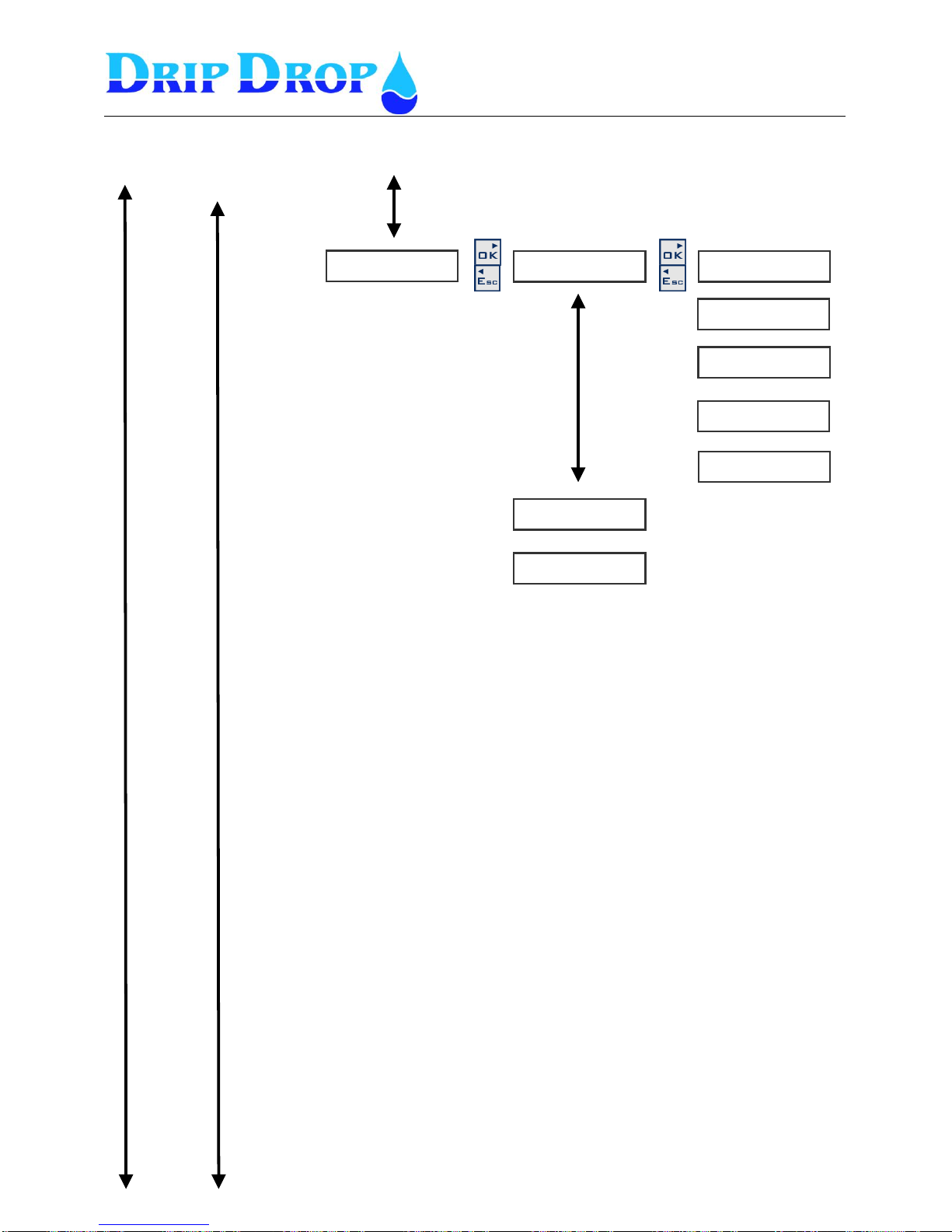
MANUAL PC-200
Ver. 2.12.xx/10/22/2010-UK
Page 53 (61)
▼▲
T e m p . s e n s o r s ►
◄
P 1 S e n s o r ►
◄◄
P 2 S e n s o r ►
◄◄
▼▲
F u n c t i o n
◄◄◄ i n u s e
S i g n a l t y p e
◄◄◄ N O
A l a r m f u n c t i o n
◄◄◄ Y e s
A l a r m d e l a y . [ s ]
◄◄◄ 1 . 0
B l o c k P u m p
◄◄◄ Y e s
P 3 S e n s o r ►
◄◄
▼▲
▼▲
▼▲
Systemsettings
I/O settings cont.
Page 54
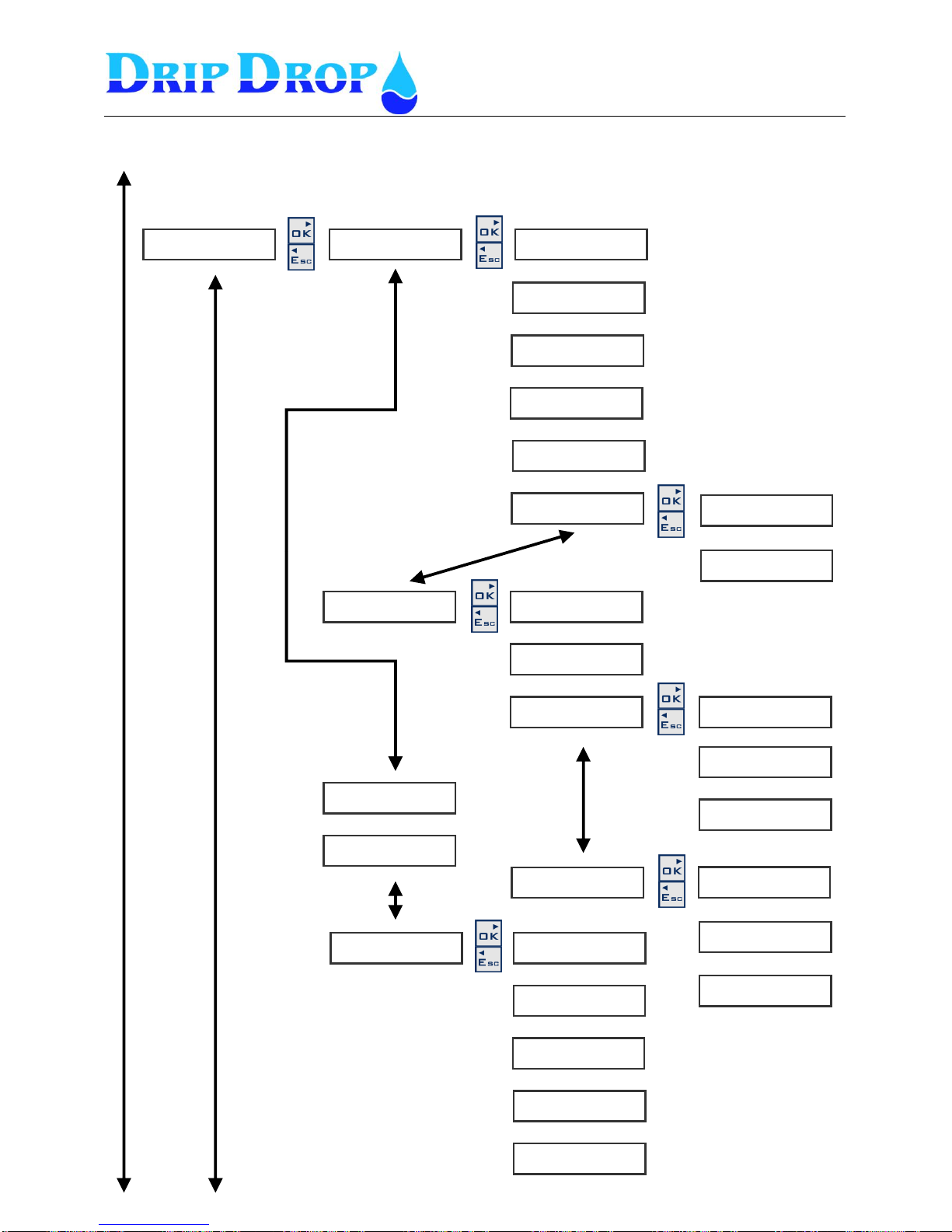
MANUAL PC-200
Ver. 2.12.xx/10/22/2010-UK
Page 54 (61)
P u m p 1 ►
◄
P u m p 2 ►
◄
P u m p 3 ►
◄
T i m e / D e l a y s ►
◄
D e l a y o n [ s ]
◄◄ 1 . 0
D e l a y o f f [ s ]
◄◄ 1 . 0
M i n t i m e s t a r t [ s ]
◄◄ 5
M i n t i m e s t o p ( s )
◄◄ 5
S w i t c h t i m e ( s )
◄◄ 2
P u m p s e t t i n g s ►
S t a r t l e v e l P 1
◄◄ 2 . 5 0
S t o p l e v e l P 1
◄ ◄ 0 . 5 0
A l t e r n a t i o n P 1
◄◄ Y e s
M a x . r u n t i m e [ m i n ]
◄◄ 7 2 0
M i n . b r e a k t i m e 1 ( s )
◄◄ 1
R u n n i n g c o n f . ►
◄◄
C o n f . t i m e [ s ]
◄◄◄ 1 0
F u n c t i o n
◄◄◄ i n u s e
C u r r e n t s e t .
◄◄
B l o c k P u m p
◄◄◄ N o
S t a r t t i m e P 1 [ s ]
◄◄◄ 0
U n d e r c u r r e n t ►
◄◄
1 - m i n [ A ]
◄◄◄◄ 0 . 0
D e l a y [ s ]
◄◄◄◄ 0
A l a r m f u n c t i o n
◄◄◄◄ N o
O v e r c u r r e n t ►
◄◄◄
1 - m a x [ A ]
◄◄◄◄ 0 . 0
D e l a y [
◄◄◄◄ 0
A l a r m f u n c t i o n
◄◄◄◄ No
▼▲
▼▲
▼▲
▼▲
▼▲
▼▲
▼▲
▼▲
▼▲
▼▲
▼▲
▼▲
▼▲
▼▲
▼▲
System settings
Pumpsettings
▼▲
Page 55
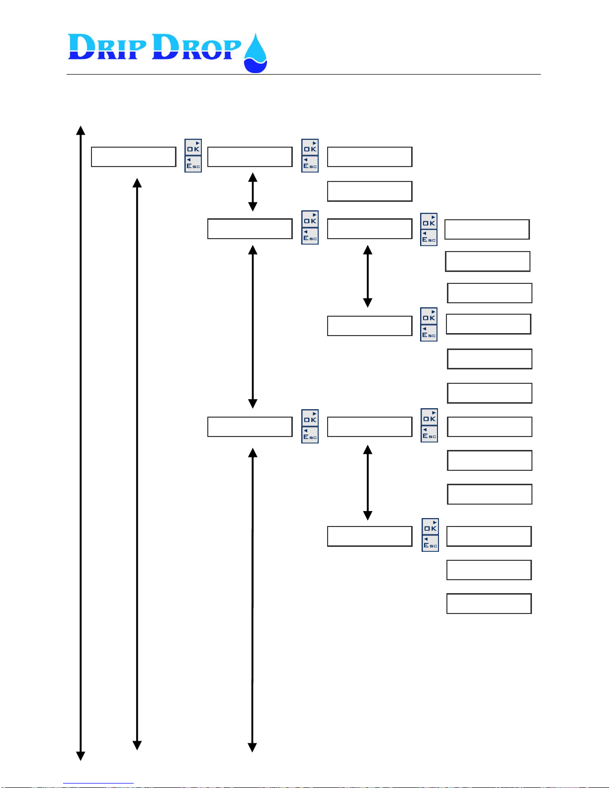
MANUAL PC-200
Ver. 2.12.xx/10/22/2010-UK
Page 55 (61)
A l t e r n a t i o n ►
◄
L o w l e v e l ►
◄◄
H i g h l e v e l ►
◄◄
L o w s e t p o i n t ►
◄◄
H i g h s e t p o i n t ►
◄◄
S t a t i o n s e t t i n g s ►
A l t e r n . t y p e
◄◄ c y c l i c
A l t e r n . o n f a i l .
◄◄ Y e s
A l a r m l e v e l s ►
◄
L o w l e v e l a l a r m
◄◄◄ 0 . 5 0
A l a r m f u n c t i o n
◄◄◄ Y e s
A l a r m d e l a y [ s ]
◄◄◄
H i g h l e v e l a l a r m
◄◄◄ 2 . 0 0
A l a r m f u n c t i o n
◄◄◄ Y e s
A l a r m d e l a y [ s ]
◄◄◄ 1
A I 2 S e t p o i n t s ►
◄
S e t p o i n t
◄◄◄ 0 . 5 0
A l a r m f u n c t i o n
◄◄◄ N o
A l a r m d e l a y [ s ]
◄◄◄ 0 . 0
S e t p o i n t
◄◄◄ 0 . 5 0
A l a r m f u n c t i o n
◄◄◄ N o
A l a r m d e l a y [ s ]
◄◄◄ 0 . 0
▼▲
▼▲
▼▲
▼▲
▼▲
▼▲
▼▲
System settings
Station settings
▼▲
▼▲
▼▲
Page 56
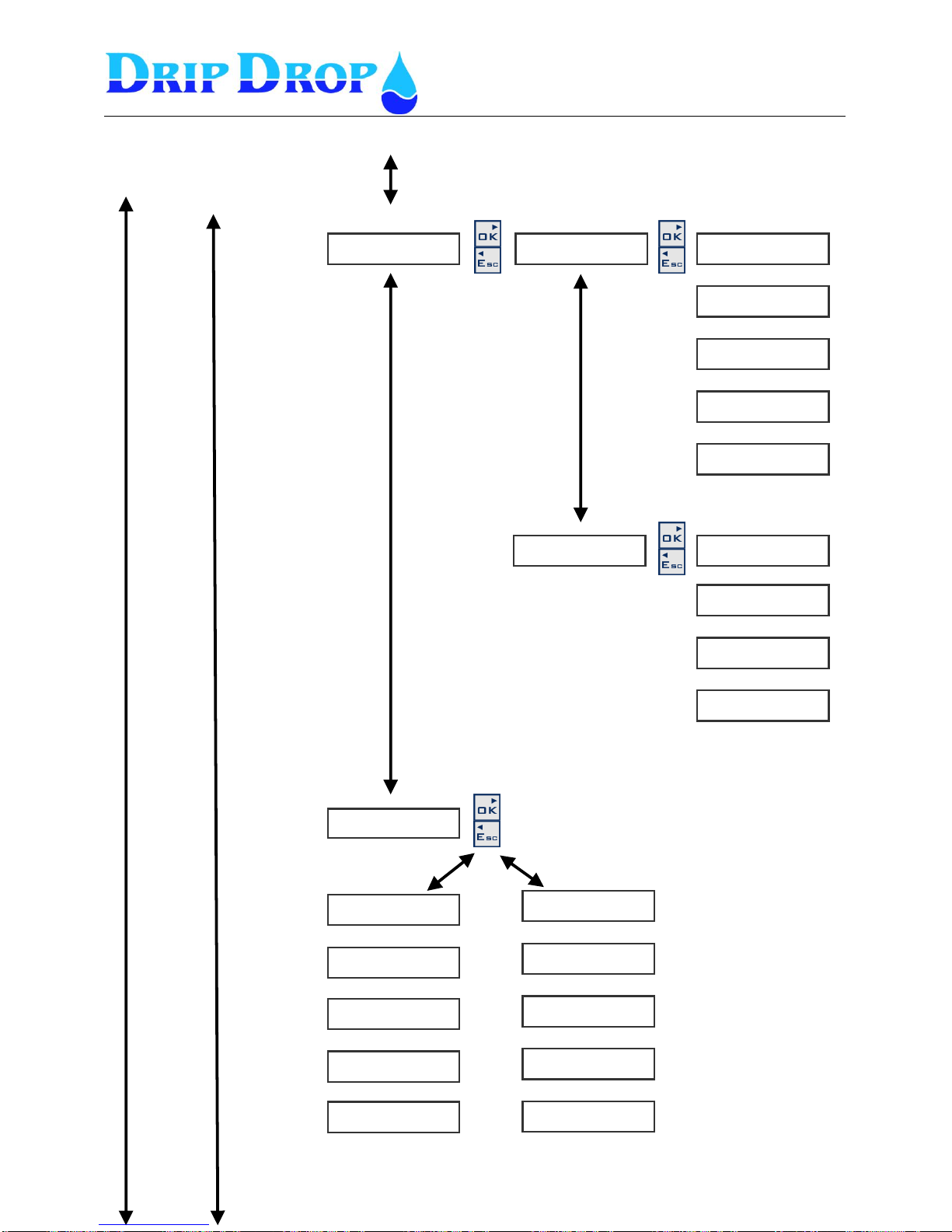
MANUAL PC-200
Ver. 2.12.xx/10/22/2010-UK
Page 56 (61)
L e v e l c o n t r o l l e d ►
◄◄
T i m e c o n t r o l l e d ►
◄◄
F u n c t i o n
◄◄ p e r s , a l a r m
F u n c t i o n
◄◄ i n t r u d e r
M i x e r s e t t i n g s ►
◄
T y p e
◄◄◄ E m p t y i n g
S t a r t c y c l e s
◄◄◄ 0
S t a r t l e v e l
◄◄◄ 0 . 0 0
S t a r t d e l a y [ s ]
◄◄◄ 0
R u n t i m e [ s ]
◄◄◄ 0
T y p e
◄◄◄ i n u s e
S t a r t a f t e r [ h ]
◄◄◄
R u n t i m e [ s ]
◄◄◄
B l o c k i f p u m p O n
◄◄◄ N o
A t t e n d . c h e c k . .►
◄
S i g n a l t y p e
◄◄◄ N C
C o n t i n o u s h o r n
◄◄◄ N o
E n t r y d e l a y [ s ]
◄◄◄ 0
E x i t d e l a y [ s ]
◄◄◄ 0
S i g n a l t y p e
◄◄ N C
C o n t i n o u s h o r n
◄◄ N o
V i s i t t i m e [ s ]
◄◄ 1 8 0 0
T i m e t o A l a r m [ s ]
◄◄ 1 8 0
▼▲
▼▲
▼▲
▼▲
▼▲
▼▲
▼▲
▼▲
▼▲
▼▲
▼▲
▼▲
▼▲
▼▲
▼▲
System settings
Station settings cont.
Page 57
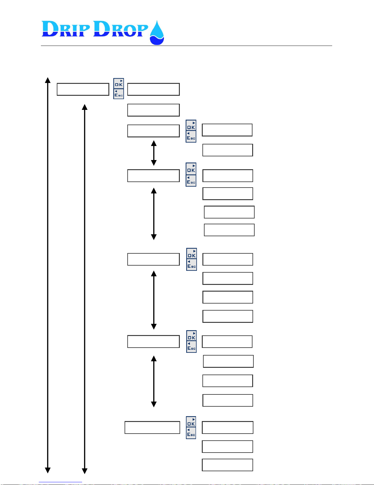
MANUAL PC-200
Ver. 2.12.xx/10/22/2010-UK
Page 57 (61)
N o m i n a l [ V ] ( L - N)
◄ 2 3 0
F a i l b r e a k t i m e [ s ]
30
P h a s e r o t a t i o n ►
◄ 2 3 0
U n d e r v o l t a g e .►
◄
F u n c t i o n
◄◄ i n u s e
B l o c k p u m p
◄◄ Y e s
F u n c t i o n
◄◄ i n u s e
B l o c k p u m p
◄◄ N o
S i g n a l d e l a y [ s ]
◄◄ 10
U n d e r v o l t a g e % .►
◄◄
O v e r v o l t a g e ►
◄
F u n c t i o n
◄◄ I n u s e
B l o c k p u m p
◄ No
S i g n a l d e l a y
◄◄ 10
O v e r v o l t a g e % .►
◄◄ 1 1 0
P h a s e u n b a l a n c e ►
◄
F u n c t i o n
◄◄ i n u s e
B l o c k p u m p
◄ No
S i g n a l d e l a y
◄◄ 10
U n b a l a n c e %
◄◄ 7
M i s s i n g p h a s e ►
◄
F u n c t i o n
◄◄ i n u s e
B l o c k p u m p
◄ No
S i g n a l d e l a y [ s ]
◄◄ 2
V o l t a g e r e l a y .►
▼▲
▼▲
▼▲
▼▲
▼▲
▼▲
▼▲
▼▲
▼▲
▼▲
▼▲
▼▲
▼▲
▼▲
System settings
Voltage relay
Page 58
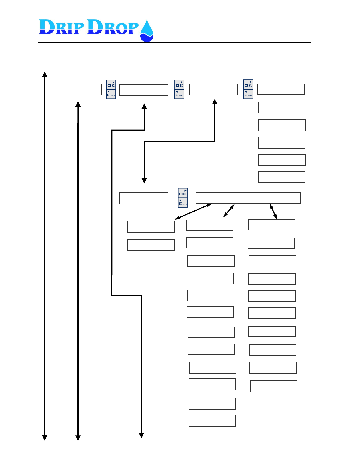
MANUAL PC-200
Ver. 2.12.xx/10/22/2010-UK
Page 58 (61)
C o m m u n i c a t i o n ►
◄
P a r i t y
◄ ◄◄ N o n e
S t o p b i t s
◄ ◄ 2
P r o t o c o l
◄◄◄ C o m l i
A d d r e s s
◄◄◄ 1
S t a t i o n I D
◄◄◄ 1
C o n n e c t i o n ►
◄◄
L i n k
◄◄◄ D i r e c t
S t a t i o n s I D
◄◄◄
H a y e s s t r i n g
◄◄◄ % r H 0 E 0 Q
M o d e m t y p e
◄◄◄
P i n c o d e
◄◄◄ 0 0 0 0
R e s e t p u l s e [ s ]
◄◄◄ 0
A l a r m r e s e n d N o
◄◄◄ 0
A n s w e r a f t e r
◄◄◄ 0
R e m o t e a c k n .
◄◄◄ N o
H a y e s s t r i n g
◄◄◄
P i n c o d e
◄◄◄ 0 0 0 0
P h o n e N o . 1
◄◄◄ 1 2 3 4 5 6
R e s e t p u l s [ s ]
◄◄◄ 0
R e m o t e a c k n .
◄◄◄ N o
S t a t i o n n a m e
◄◄◄
C a l l a l a r m O FF
◄◄◄ N o
M i s c e l l a n e o u s ►
C o m m . s e t t i n g s ►
◄◄
B a u d r a t e [ b p s ]
◄◄◄ 9 6 0 0
L i n k
◄◄◄Direct D i a l u p / G S M - S M S G S M / S M S
L i n k
◄◄◄ D i a l u p
L i n k
◄◄◄ G S M - S M S
R e s e t m o d e m [ m ]
◄◄◄ 0
P h o n e N o . 1
◄◄◄ 1 2 3 4 5 6
C o n n e c t . s t r i n g
◄◄◄ 0
R e s e t m o d e m
◄◄◄ 0
P h o n e N o . 3
◄◄◄ 1 2 3 4 5 6
P h o n e N o . 2
◄◄◄ 1 2 3 4 5 6
▼▲
▼▲
▼▲
▼▲
▼▲
▼▲
▼▲
▼▲
▼▲
▼▲
▼▲
▼▲
▼▲
▼▲
▼▲
▼▲
▼▲
▼▲
▼▲
▼▲
▼▲
▼▲
▼▲
▼▲
▼▲
▼▲
System settings
Miscellaneous
Page 59
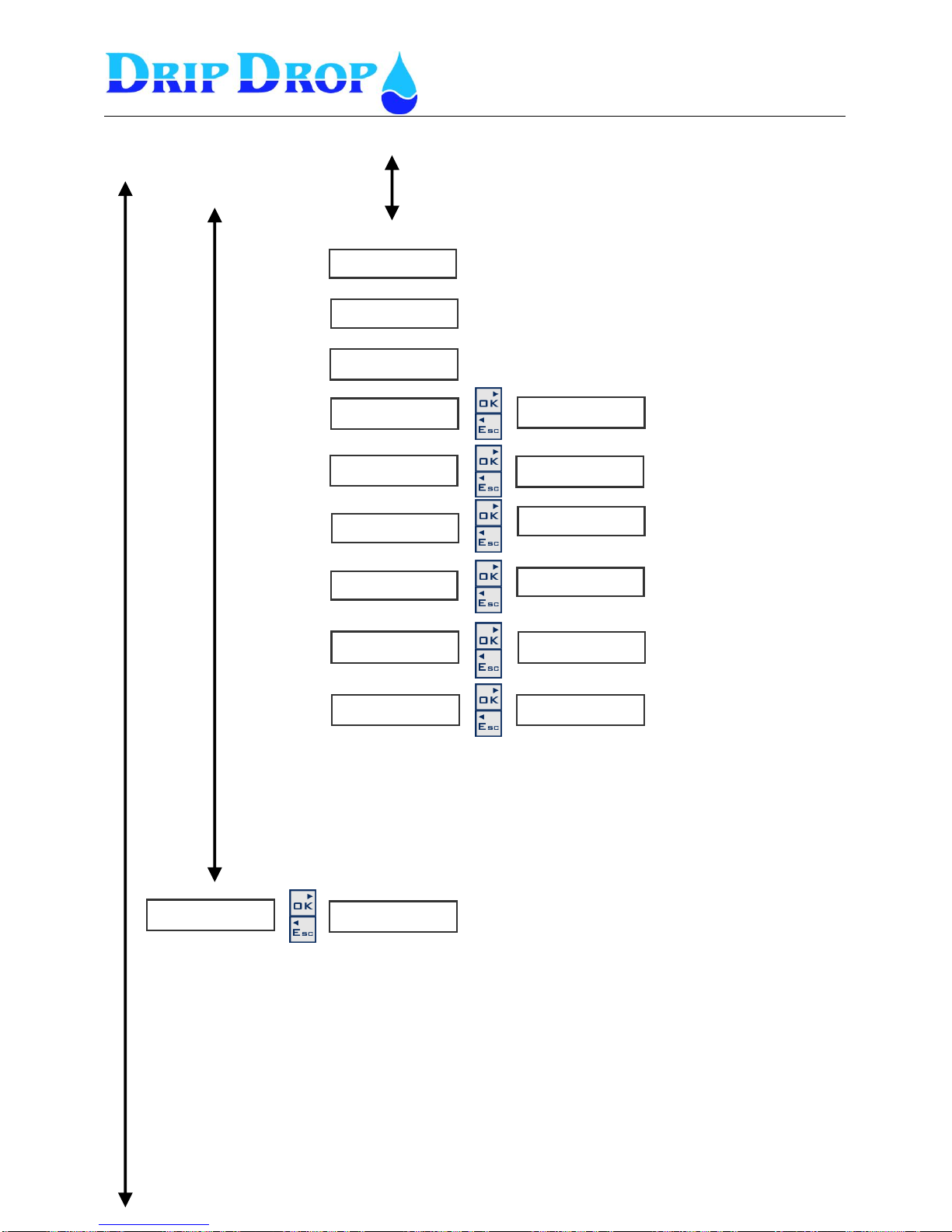
MANUAL PC-200
Ver. 2.12.xx/10/22/2010-UK
Page 59 (61)
S y s t e m c o d e
◄ 0 0 0 0
C l o c k s e t t i n g ►
◄
D e f a u l t s e t t i n g ►
◄
E r a s e r u n t i m e s ►
◄
C o n t r a s t ►
◄
C l o c k s e t t i n g
1 1 / 0 5 1 2 : 5 7 : 1 1
D e f a u l t s e t t i n g
A r e y o u s u r e ?
C o n t r a s t
■■■■■■■■■
L o g i n / l o g o u t
P a s s w o r d
Z Z Z Z
T r u s t e d l o g i n
◄ No
O p e r a t o r c o d e
◄ Z Z Z Z
E r a s e a l a r m ►
◄
E r a s e c o u n t e r s ►
◄
E r a s e a l a r m l i s t ?
A r e y o u s u r e ?
E r a s e c o u n t e r s
A r e y o u s u r e ?
E r a s e r u n t i m e s
A r e y o u s u r e ?
▼▲
▼▲
▼▲
▼▲
▼▲
▼▲
Use▼▲ keys to set Password
Factory settimg is
Operator password is ZZZZ (▼▼▼▼)
System Password is 0000 (Zeros) (▲▲▲▲)
▼▲
▼▲
Systemsettings
Miscellaneous cont.
Page 60
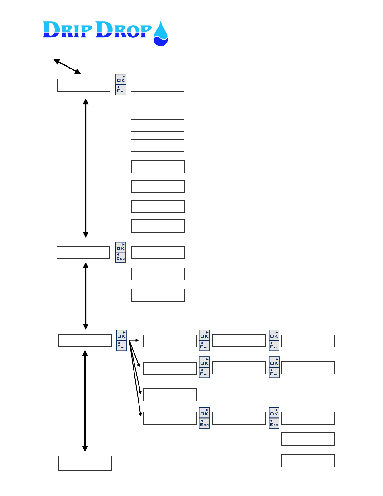
MANUAL PC-200
Ver. 2.12.xx/10/22/2010-UK
Page 60 (61)
S t a r t L e v e l 1 [ m ]
2 . 5 0
S t o p L e v e l 1 [ m ]
◄ 0 . 3 0
S t a r t l e v e l 2 [ m ]
◄ 2 . 60
S t o p l e v e l 2 [ m ]
◄ 0.70
S t a r t l e v e l 3 [ m ]
◄ 2.80
S t o p l e v e l 3 [ m ]
◄ 0.70
L o w l e v e l [ m ]
◄ 0 . 3 0
H i g h l e v e l [ m ]
◄ 3 . 0 0
P 1 M a n s t a r t
N o t a l l o w e d
S t a r t P 2
S t a r t P 3
* N o t A c k . a l a r m s
A l l a l a r m s
D a t e : 0 5 / 0 3
T i m e : 1 2 . 3 5
P 1 M o t o r p r o t e c t .
A c t i v e A c k n ?
P 1 M o t o r p r o t e c t .
A c k n o w l e d g e ?
P 1 M o t o r p r o t e c t .
O n : 2 5 / 1 0 1 0 : 5 5
P 1 M o t o r p r o t e c t .
O f f : 0 0 / 0 0 0 0 : 0 0
* A c t i v e a l a r m s
A l l a l a r m s
* N o n e w a l a r m s
A l l a l a r m s
P 1 M o t o r p r o t e c t .
A c t i v e
P 2 M o t o r p r o t e c t .
A c t i v e
* N o n e w a l a r m s
A l l a l a r m s
P 1 M o t o r p r o t e c t .
A c t i v e
P 1 M o t o r p r o t e c t .
A c k . : 0 0 / 0 0 0 0 : 0 0
L e v e l s e t t i n g s ►
▼▲
▼▲
▼▲
▼▲
▼▲
▼▲
▼▲
M a n . S t a r t / S t o p ►
▼▲
▼▲
A l a r m S t a t u s ►
▼▲
▼▲
▼▲
Page 61

MANUAL PC-200
Ver. 2.12.xx/10/22/2010-UK
Page 61 (61)
Notes
 Loading...