


Installation Guide
English
1000 Pro Series
Countertop
Purier·Dispenser·Sterilizer
Model: DP1000(B)
Customer Assistance
1-844-374-6576
www.drinkpod.com
Drinkpod and the Drinkpod logo are the registered
trademarks of Drinkpod, LLC.
All Rights Reserved.

Table Of Contents
IMPORTANT SAFETY INSTRUCTIONS 1
GETTING STARTED 1-2
Installation Components List 1-2
Conguration & Location 2-4
Preparation 2-9
Tapping Water Source 2-11
INSTALLING YOUR WATER 1000 PRO SERIES 2-11
Running Water Source Line 2-23
Flushing Your Filters 2-26
Connecting Accessory Appliances 2-33
Connecting Water 1000 Pro Series 2-43
Installing Filters 2-46
Optional - Expanding Purication Capabilities 2-47
Enabling Water Flow 2-53
APPENDICES 2-56
Appendix A - Water Sources 2-56
Appendix B - Component Connections 2-61
NOTES 2-64
Table of Contents

Important Safety Instructions
When using electrical appliances, basic safety precautions should always be followed,
including the following:
1. Read all instructions.
2. Should your appliance ever fail, please disconnect the power and water immediately before
calling for assistance.
3. To avoid leakage and damage, never remove appliance parts.
4. Unsupervised children should not be allowed to operate the machine.
5. Please use the product in a dry place within the temperature ranges of 40°F and 100°F.
6. Ensure the power cord is always unplugged before performing any maintenance,
troubleshooting, or lter upgrades.
7. Only use Kenmore or Drinkpod accessories and lters to avoid causing damage and voiding
product warranty.
8. For all service and support related issues, please contact Drinkpod. 1-844-374-6576 or
support@drinkpod.com
9. Any and all repairs should only be attempted by qualied persons designated by Drinkpod.
10. Do not install the machine in a location exposed to direct sunlight.
11. Never store or expose your Drinkpod 1000 Pro Series in an environment less than 32°F.
12. This appliance is not intended for use by persons with reduced physical, sensory, or mental
capabilities, or lack of experience and knowledge, unless they have been given supervision or
instruction concerning use of the appliance by a person responsible for their safety. Children
should be supervised to ensure they do not play with the appliance.
13. If the supply cord is damaged, it must be replaced by the manufacturer, one of its designated
service agents, or similarly qualied person, in order to avoid all hazards.
14. Do not store explosive substances such as aerosol cans, or other items with a ammable
propellant, in this appliance.
15. This appliance is intended to be used in household and similar applications, kitchens, oces,
and similar non-retail applications.
16. The appliance should only be plugged into a grounded three prong socket. A surge protector is
recommended.
17. The appliance should never be turned upside down, or tilted more than 45°.
18. The appliance should never be cleaned utilizing a compressed water stream.
19. This product is designed for household use only!
20. WARNING: To avoid any hazards due to instability of the appliance, it must be
installed, maintained, and repaired, in accordance with this manual.
SAVE THESE INSTRUCTIONS!
Important Safety Instructions 1
Getting Started
Installation Components List
Included with your Drinkpod 1000 Pro Series are a broad assortment of installation
accessories. Do not get overwhelmed. While it is highly unlikely that you will require all of
them, working with anything connected to your homes water system can be the wild west,
and plumbers are rogue gunslingers. That’s why we’ve done our best to provide enough
accessories to accommodate almost any scenario, and easy to understand instructions to
guide you through the process.
We highly recommend leaving the installation accessories in their labeled tray
until you are instructed to remove them.
A
B
D
C
E
F
H
I
G
J
K
Getting Started 1-2

Getting Started
A: 25’ Coil of 1/4 in. White PP Tubing
B: 1/4 in. Compression To Quick Connect Adapter (x6)
C: 1/4 in. Quick Connect Shuto Valve (x2)
D: 1/4 in. Brass Compression Union
E: 1/4 in. Brass Compression Tee
F: 3/8 in. Sink Adapter Valve (1/4 in. Custom x 3/8 in. Male x 3/8 in. Female x
Compression Steel Angle Stop Valve Adapter)
G: Filter Flushing Attachment
H: Expansion Filter Mounting Bracket
I: Expansion Filter EZ-Twist Mount
J: Expansion Filter Source Line
K: Expansion Filter Appliance Line
Getting Started 1-3

Getting Started
Before we proceed with your installation, we must rst identify how and where to install
your new Drinkpod 1000 Pro Series. This will be the most complicated part of the installation
process. Don’t be intimidated! We’ve worked hard to write the best set of instructions you’ll
ever read. Be prepared to feel like a DIY pro when you’re nished!
Conguration & Location
First, let’s decide where you want to install your Drinkpod 1000 Pro Series. In almost all
cases, this easily decided by answering two simple questions.
1. What water sources are available? If you’re not sure what you have, or how to check,
see “Appendix A - Water Sources” on page 2-56 for pictures and more information.
A.
Water Accessory Line (typically refrigerator ice maker line/source)
B.
Sink Faucet Cold Water Line (i.e. underneath your kitchen sink)
2. Do you want to connect any other appliances? Your Drinkpod 1000 Pro Series is
capable of providing puried water to up to two kitchen appliances* (i.e. refrigerator,
ice maker, or coee maker/espresso maker/barista machine with an in-line water
connection).
*The ability to provide purified water to external appliances is dependent on having
sufficient water pressure.
3. Following this are diagrams of the most common types of installations our customers
like to use. Quickly review them to identify which conguration best suits you. We
recommend connecting to a Water Accessory Line if both types of water sources are
available.
Getting Started 2-4
Getting Started
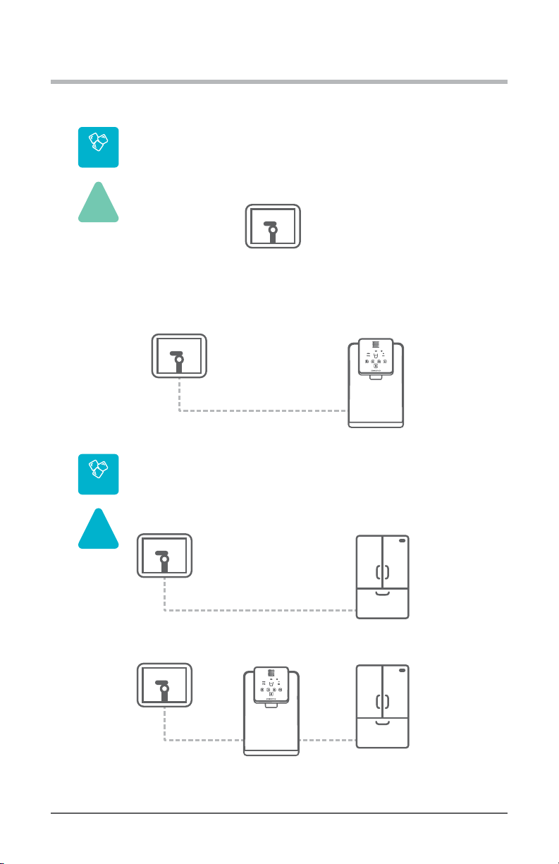
Example Installation #1.1
Accessory Water Line Source
BEFORE
Accessory Water Source
(Ice Maker)
AFTER
Accessory Water Source
(Ice Maker)
1000 Pro Series
(Ice Maker Connection)
Example Installation #1.2
Accessory Water Line Source - 1x Accessory Appliance
BEFORE
Accessory
Water Source
Refrigerator
(Ice Maker Connection)
AFTER
Accessory
Water Source
Refrigerator
(Ice Maker Connection)
1000
Pro Series
Accessory Water Line Congurations
source
0x
acc.
Diagram 2.1.1-A Accessory Water Line Source (Not Connected, No Accessory Appliances)
source
1x
acc.
Diagram 2.1.1-B Accessory Water Line Source (Connected, 1 Accessory Appliance)
Getting Started 2-5
Getting Started
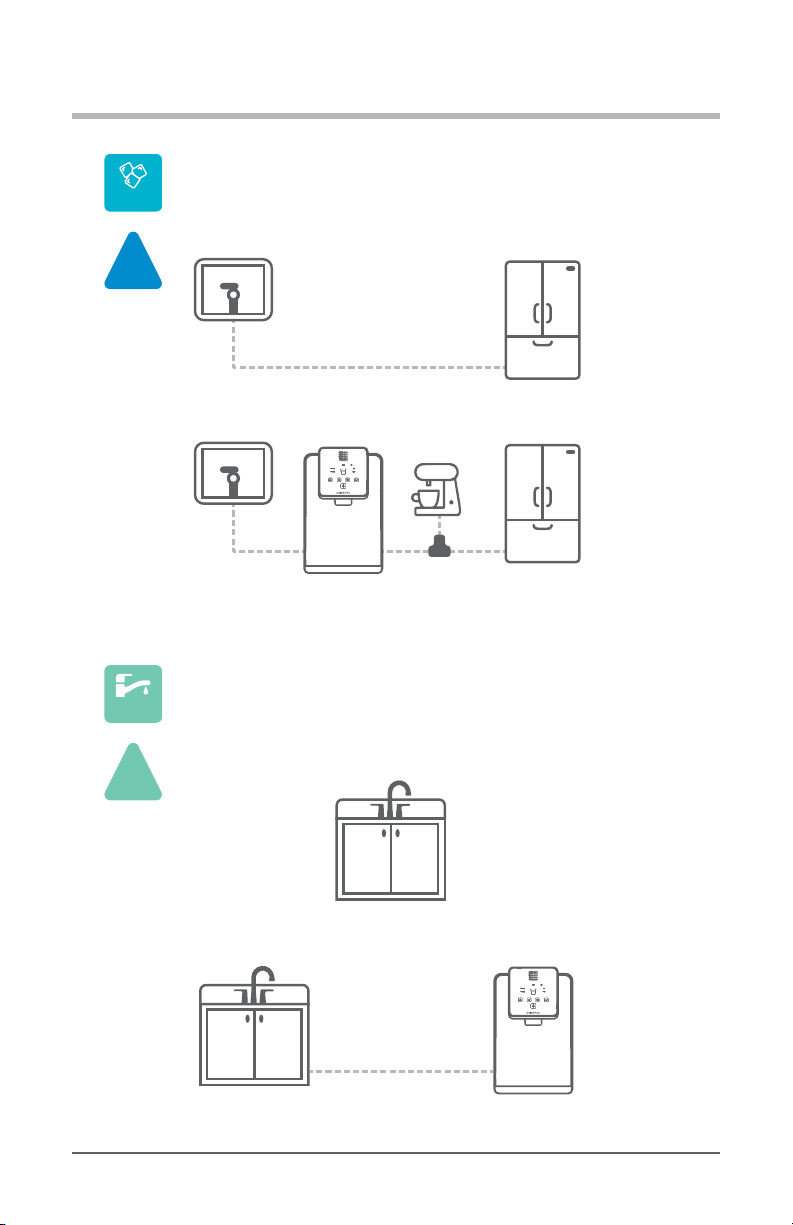
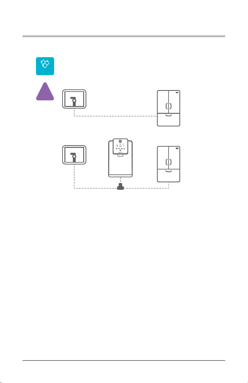
Example Installation #1.3
Accessory Water Line Source - 2x Accessory Appliances
BEFORE
Accessory
Water Source
Refrigerator
(Ice Maker Connection)
AFTER
Accessory
Water Source
Refrigerator
(Ice Maker Connection)
1000
Pro Series
Coffee Maker
(Input Port)
Example Installation #2.1
Sink Faucet Cold Water Line Source
BEFORE
Sink Faucet Water Source
(Under Kitchen Sink)
AFTER
1000 Pro Series
(Sink Faucet Connection)
Sink Faucet Water Source
(Under Kitchen Sink)
source
2x
acc.
Diagram 2.1.1-C Accessory Water Line Source (Connected, 2 Accessory Appliances)
Sink Faucet Cold Water Line Congurations
source
0x
acc.
Diagram 2.1.2-A Faucet Cold Water Line Source (No Accessory Appliances)
Getting Started 2-6
Getting Started
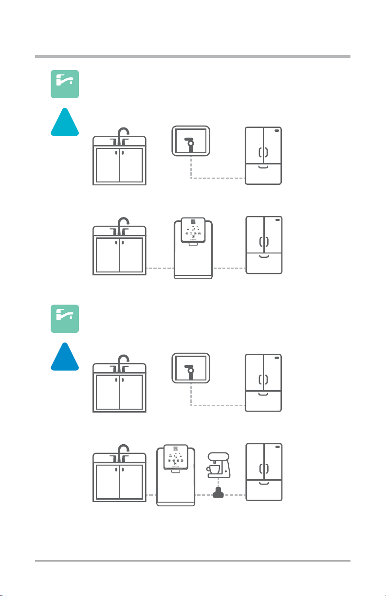
1000
Pro Series
Refrigerator
(Ice Maker Connection)
Refrigerator
(Ice Maker Connection)
Example Installation #2.2
Sink Faucet Cold Water Line Source - 1x Accessory Appliance
BEFORE
Sink Faucet Water Source
(Under Kitchen Sink)
Sink Faucet Water Source
(Under Kitchen Sink)
AFTER
Accessory
Water Source
source
1x
acc.
Diagram 2.1.2-B Faucet Cold Water Line Source (1 Accessory Appliance)
Example Installation #2.3
Sink Faucet Cold Water Line Source - 2x Accessory Appliances
source
Sink Faucet Water Source
(Under Kitchen Sink)
2x
acc.
BEFORE
Accessory
Water Source
Refrigerator
(Ice Maker Connection)
Sink Faucet Water Source
(Under Kitchen Sink)
Diagram 2.1.2-C Faucet Cold Water Line Source (2 Accessory Appliances)
Pro Series
1000
AFTER
Coffee Maker
(Input Port)
Refrigerator
(Ice Maker Connection)
Getting Started 2-7
Getting Started
Alternative Conguration
source
P
acc.
Accessory Water Line Source - Low Pressure Alternative
Accessory
Water Source
Accessory
Water Source
Diagram 2.1.3 Low Water Pressure Alternative (Shared in Parallel)
4. It’s almost time to choose where to install your new Drinkpod 1000 Pro Series. You should
have a pretty good idea based on available space and whichever conguration you
selected. There’s only one remaining factor you need to consider, and that is your tubing
(water lines).
Example Installation #3
BEFORE
AFTER
1000
Pro Series
Refrigerator
(Ice Maker Connection)
Refrigerator
(Ice Maker Connection)
5. Your water source, 1000 Pro Series, and any accessory appliances all need to be
connected by the white ¼ in. PP tubing (included in your installation kit) or existing
water line hose. Take a moment to visualize where you’ll need to run your water tubing,
and visually inspect any potential trouble areas, and adjust your plans accordingly.
Below are a two examples:
A.
Cabinets separating your 1000 Pro Series from a water source or appliance,
requiring you to route tubing over/under, or drill holes.
B.
Lack of vertical access from your water source under your sink to above your
counter-top, requiring drilling holes to run the tubing inside your cabinets, or
through your counter-top.
Congratulations, the most dicult part is out of the way! Let’s get started
Getting Started 2-8

Getting Started
Preparation
Before we start tapping your water source, there are a few items you need to grab that
weren’t included in your installation kit.
•
Sharp Knife or Scissors
•
Pliers, or Adjustable Wrench, or Open-End 7/16 in. Wrench (all installations),
1/2 in. Wrench (most installations), and 11/16 in. Wrench (*sink water source
installation only)
•
Container To Drain Water Into (i.e. bucket, bowl, or pitcher)
•
Flashlight or Lamp (if under sink installation area is poorly lit)
•
Drill (if drilling holes to run tubing is required)
7/16 in.
or or or
Diagram 2.0.1 Additional Items Needed For Installation
1. Remove the 1000 Pro Series and lters from the packaging and set them aside.
2. Let’s get started. If your plan is to utilize your Accessory Water Line as your source,
proceed below for Option A (Accessory Water Line). Alternatively, if you plan to use
your sink faucet cold water line as your source, turn to “Option B: Tapping Faucet
1/2 in.
+
11/16 in.
+
Getting Started 2-9
*

Getting Started
Cold Water Line” on page 2-16.
Getting Started 2-10

Installing Your Water 1000 Pro Series
A
Tapping Water Source
Option A: Tapping Accessory Water Line
source
In this section, you will require 1/4 in. White PP Tubing, and may also need B
1/4 in. Compression To Quick Connect Adapter, and pliers, or an adjustable wrench or
1/2 in. wrench.
1. If nothing is currently connected to your water accessory line, skip forward to Step
#7 on page 2-14.
2. If appliance is connected to water accessory line, start by powering o and
unplugging the appliance.
3. Pull the refrigerator (or other appliance) away from wall suciently to allow access to
wall and oor behind it.
Diagram 2.3A.3 Pulling Back Appliance To Access Water Source Line & Valve
4. In most scenarios, your shuto valve and connection will look similar to the rst diagram
below. We’ve also included the second and third most common setups in the proceeding
diagrams. The instructions should remain accurate, regardless of which setup yours is, as
long as it incorporates a shuto valve. Should the latter not be the case, you will have to
locate the shuto valve before proceeding.
Installing Your Water 1000 Pro Series 2-11

Installing Your Water 1000 Pro Series
Diagram 2.3(A).4-A Wall Mounted Accessory Water Line Source
Diagram 2.3(A).4-B Floor Mounted Accessory Water Line Source
Installing Your Water 1000 Pro Series 2-12

Installing Your Water 1000 Pro Series
Diagram 2.3(A).4-C Unmounted/Free Accessory Water Line Source
5. Turn the valve handle clockwise until it stops to shut o water ow.
Diagram 2.3(A).5-A/B Closing Source Valve
Installing Your Water 1000 Pro Series 2-13

Installing Your Water 1000 Pro Series
6. Now, use pliers, adjustable or 1/2 in. wrench, to disconnect the appliance water line
from the source shuto valve. If you’re unsure how to disconnect the water line, see
“Appendix B - Component Connections” on page 2-60. If its already adapted to
quick connect (see ) leave the adapter, and disconnect the tubing.
Diagram 2.3(A).6-A Disconnect Appliance Water Line (Compression)
Diagram 2.3(A).6-B Disconnect Appliance Water Line (Quick Connect)
7. If the water source shuto valve isn’t already Quick Connect, connect B
1/4 in. Compression To Quick Connect Adapter to Accessory Water Line Shuto
Installing Your Water 1000 Pro Series 2-14

Installing Your Water 1000 Pro Series
A
Valve.
Diagram 2.3(A).7 Connect Compression-To-Quick Connect Adapter
8. Connect one end of 1/4 in. White PP Tubing to B
1/4 in. Compression To Quick Connect Adapter.
Diagram 2.3(A).8 Connect Tubing To Water Source
9. Congratulations! You’ve just completed the second most dicult part of your installation.
Now jump ahead to “Running Water Source Line Step #4” on page 2-23.
Installing Your Water 1000 Pro Series 2-15

Installing Your Water 1000 Pro Series
Option B: Tapping Faucet Cold Water Line
source
1. For this section, you will need F 3/8 in. Sink Adapter Valve, as well as pliers, a
crescent wrench, or 7/16 in. and 11/16 in. open ended wrenches (see “Preparation” on
page 2-9).
Diagram 2.3(B).1 Connect Compression-To-Quick Connect Adapter
2. Open your cabinet doors to reveal the plumbing underneath your sink. Don’t get
overwhelmed by all the piping and connections. We’ve provided a diagram with
labels to help you understand what you’re looking at (accurate for most under sink
setups). The blue items listed below are ll that we’ll be working with.
KS-A:
KS-B:
KS-C:
KS-D:
KS-E:
KS-F:
KS-G:
KS-H:
KS-I:
Installing Your Water 1000 Pro Series 2-16
Left Drain
Hot Faucet Handle
Hot Water Feed Line
Hot Water Shuto Valve
Faucet
Cold Water Shuto Valve
Cold Water Feed Line
Cold Faucet Handle
Garbage Disposal
Installing Your Water 1000 Pro Series
KS-J:
KS-A
Right Drain
KS-B
KS-E
KS-H
KS-I
KS-C KS-G
KS-J
KS-D
Diagram 2.3(B).2 Under Sink Reference Diagram
3. We will be tapping the cold water line, which is typically on the right, but its always
smart to conrm the plumber didn’t take any ‘creative liberties’. Begin by turning on the
cold water at your faucet
KS-H
. .
KS-F
Installing Your Water 1000 Pro Series 2-17

Installing Your Water 1000 Pro Series
Diagram 2.3(B).3 Turn On Cold Water In Sink
4. Now turn the handle of
any further. If your faucet stops pouring water, we’ve conrmed this is your cold water
shuto. If it doesn’t turn o, then it is the valve on the left.
5. Use our pliers, crescent wrench, or 11/16 in. wrench to loosen
Cold Water Feed Line from
FITS, continue to loosen and detach the hose, and proceed. IF IT DOESN’T FIT, the
KS-F
Cold Water Shuto Valve clockwise until it won’t turn
Diagram 2.3(B).4 Shuto Cold Water Source Valve
KS-G
KS-F
Cold Water Shuto Valve. IF THE WRENCH
Installing Your Water 1000 Pro Series 2-18

Installing Your Water 1000 Pro Series
connection is almost certainly a ½ in. (Nominal/NPT) tting. If you have a 15/16 in. and
a 1 in. wrench, you can check to conrm by attempting to loosen the connection (there
is 1/16 in. range of variance between dierent plumbing ttings). IF THAT DOESN’T FIT,
you have an extremely rare setup, and should contact a plumber. IF THE LARGER
WRENCH DOES FIT, we don’t provide 1/2 in. adapter in your kit (only 2.5% of our
customers require it), but we’d be more than happy to ship you one for free upon request.
Call us at 1-844-374-6576, or email us at support@drinkpod.com. Or, if you don’t
want to wait, you can pick one up at your local hardware store. Ask for a 1/2 in (FIP) x
1/2 in. (MIP) x 1/4 in (OD) Push-to-Connect Angle Stop Adapter Valve.
Diagram 2.3(B).5 Detach Cold Water Feed Line
6. Next, screw the bottom (female) end of F 3/8 in. Sink Adapter Valve to the
top (male) end of
using medium force with the same wrench (11/16 in.) you used to remove
Cold Water Feed Line.
KS-F
Cold Water Shuto Valve using your hand. Then tighten
Installing Your Water 1000 Pro Series 2-19
KS-G

Installing Your Water 1000 Pro Series
Diagram 2.3(B).6 Attach Sink Adapter Valve To Cold Water Shuto Valve
7. Now using your hand, screw the (female) end of
the top (male) end of F 3/8 in. Sink Adapter Valve, and use wrench to tighten
using medium force.
Diagram 2.3(B).7 Attach Cold Water Feed Line To Sink Adapter Valve
8. Let’s conrm there are no leaks. Check to make sure the valve on part F
3/8 in. Sink Adapter Valve is closed (pointing downward as shown above). Next,
KS-G
Cold Water Feed Line onto
Installing Your Water 1000 Pro Series 2-20

Installing Your Water 1000 Pro Series
A
open the ow on
1-2. Water should pour from faucet, and nothing should be no leaking below. If there
are leaks, tighten connections with wrench, then turn o
9. With your hand, unscrew and remove the compression nut from the side of F
3/8 in. Sink Adapter Valve.
KS-F
Cold Water Shuto Valve by repeating “Step 4” on page
KS-H
faucet and proceed.
Diagram 2.3(B).9 - Unscrew Compression Bolt From Sink Adapter Valve
10. Uncoil end of 1/4 in. White PP Tubing, and thread through the small end of nut.
Diagram 2.3(B).10 - Thread Tubing Through Compression Nut
Installing Your Water 1000 Pro Series 2-21

Installing Your Water 1000 Pro Series
11. Now stretch the same end of A 1/4 in. White PP Tubing over the ‘nipple’ of F
3/8 in. Sink Adapter Valve’s side connection until it butts up against the threads. This
may require pressing very rmly and twisting back and forth.
Diagram 2.3(B).11 - Stretch/Press Tubing Over Sink Adapter Valve Compression Nipple
12. Using your hand to screw nut back onto threads of F 3/8 in. Sink Adapter Valve,
then tighten with pliers, or 7/16 in. wrench.
Diagram 2.3(B).12 - Screw Compression Nut Back Onto Sink Adapter Valve
Congratulations! You’ve just completed the second most dicult part of your installation.
Now jump ahead to “Running Water Source Line Step #4” on page 2-23.
Installing Your Water 1000 Pro Series 2-22

Installing Your Water 1000 Pro Series
Running Water Source Line
It’s time to run your water line (tubing) from your water source to where your
1000 Pro Series will be place. For this section, you will require
1. Uncoil and run A 1/4 in. White PP Tubing, from where its connected (to your water
source) to wherever you intend to locate your 1000 Pro Series. Make any necessary
adjustments (i.e. drilling holes) as you go.
2. Once you have the water line tubing ran all the way to where your 1000 Pro Series will
be placed, measure out a 1 - 2 ft. of additional tubing. You want to ensure you have
sucient slack to pull the 1000 Pro Series away from the wall for maintenance.
3. Cut the tubing using your scissors or knife. Be careful to cut the tubing straight across (at
a 90 degree angle) to avoid leaks.
Diagram 2.4.3 Cut Tubing
4. Now, insert the open end of A 1/4 in. White PP Tubing into one end (doesn’t matter
which) of C 1/4 in. Quick Connect Shuto Valve. Continue to rmly insert tubing
into opening until it won’t go any further. Then pull tubing backwards (away) from valve,
using medium force, to engage/extend the compression sleeve on the valve, and ensure
the connection is secured.
Installing Your Water 1000 Pro Series 2-23

Installing Your Water 1000 Pro Series
Diagram 2.4.4 Connect Tubing To Shuto Valve
5. Make sure the valve handle is closed by turning it clockwise as far as it will go. When
closed, the handle extends out perpendicularly to the length of the shuto valve.
Diagram 2.4.5 Ensure Valve Is Closed
6. Once you’ve conrmed that the valve is closed, open the valve at your water source (by
turning counter clockwise) to enable the water to ll the tubing, ensuring there are no
leaks in either end of the connections to the water line.
Installing Your Water 1000 Pro Series 2-24

Installing Your Water 1000 Pro Series
Diagram 2.4.6-A - Open Icemaker Source
Diagram 2.4.6-B - Open Sink Source
7. If there are no leaks, you’re doing great, and are ready to proceed to the next stage,
”Flushing Your Filters” on page 2-26. If there is a leak, shut o the water ow. Review
the connections and “Steps 3 - 5” on page 2-23 to correct your leak, and proceed
to the next stage.
Installing Your Water 1000 Pro Series 2-25

Installing Your Water 1000 Pro Series
A
Flushing Your Filters
Certain types of lters require ushing prior to use. This is important for both the lters
lifespan, and the long term lifespan of your Drinkpod 1000 Pro Series. Additionally,
replacements for these types of lters should be ushed each time one is replaced,
prior to installing. For your 1000 Pro Series, the lter that requires ushing is the
ULTRA+3 Hybrid Scrub .
This section will require A 1/4 in. White PP Tubing, G Filter Flushing Attachment,
the lters listed above, scissors, and a container to ush water into (if your sink isn’t within
reach of your water line).
1. Begin by cutting a 3 ft. to 5 ft. section of 1/4 in. White PP Tubing. Make sure to
cut the tubing at a 90 degree (perpendicular) angle.
Diagram 2.5.1 Cut Tubing Perpendicularly
2. Next, insert one end to the labeled IN port on G Filter Flushing Attachment. Be
sure to forcefully push tubing all the way into the QC input until it won’t insert any further.
Installing Your Water 1000 Pro Series 2-26

Installing Your Water 1000 Pro Series
Diagram 2.5.2 Insert Tubing Into Quick Connect Input Port
3. Now pull backwards on tubing, away from attachment,
extending the QC sleeve, and ensuring the connections is ‘locked’.
Diagram 2.5.3 Pull & Lock Quick Connect Connection
4. This will be your ‘Filter Flushing Setup’ that you will save and use every time you
replace your lters. The OUT port is where the water will be ushed out.
You can cut another piece of tubing (to whatever length you need) if you wish to have
additional line to run wherever you intend to dispense the ushed water into.
Installing Your Water 1000 Pro Series 2-27
Optional
-

Installing Your Water 1000 Pro Series
Diagram 2.5.4 OPTIONAL Connect Drain Line To Flushing Accessory ‘OUT’ Port
5. Follow the same steps to connect the open end of the IN line (not the OUT line)from
your G Filter Flushing Attachment, and connect it to the open port on your C
1/4 in. Quick Connect Shuto Valve connected to your Water Source Line.
Diagram 2.5.5 Connect Filter Flushing Setup To Water Source Line
6. Next, insert the ULTRA+3 Hybrid Scrub up into G Filter Flushing Attachment
while twisting it clockwise until it locks into place.
Installing Your Water 1000 Pro Series 2-28

Installing Your Water 1000 Pro Series
Diagram 2.5.6 Connect Chemical Filter To Filter Flushing Accessory
7. Place the lter and G Filter Flushing Attachment in your sink or container (for
draining water). Ensure the labeled ‘OUT’ port is pointed to direct water down - so the
ushed water doesn’t spray up into the air.
Diagram 2.5.7 Aim Filter & Flush Accessory Down Into Sink/Container
8. Now, turn the handle counter-clockwise on C 1/4 in. Quick Connect Shuto Valve
to start the water ow.
Installing Your Water 1000 Pro Series 2-29

Installing Your Water 1000 Pro Series
Diagram 2.5.8 Open Quick Connect Valve
9. Flush the lter for a total of 2 minutes. Then shut o the water ow, and disconnect the
lter. Be careful to set the lter down upright on a solid surface, to avoid spilling the
water remaining in the lter.
Diagram 2.5.9 Flush For 2 Minutes
10. Remove the lter from your ushing setup.
Installing Your Water 1000 Pro Series 2-30

Installing Your Water 1000 Pro Series
Diagram 2.5.10 Connect & Flush Polishing Filter
11. Now push the tubing (running from G Filter Flushing Attachment to C
1/4 in. Quick Connect Shuto Valve back into the valve as far as possible. Then,
while using your thumb to keep the QC sleeve fully depressed, gently pull the tubing out
of the port.
Diagram 2.5.11 Disconnecting Filter Flushing Setup From Water Source
12. Be sure to store the your ‘Filter Flushing Setup’ somewhere safe and accessible for
each time you replace your lters.
Installing Your Water 1000 Pro Series 2-31

Installing Your Water 1000 Pro Series
13. Now, if you plan to connect any other appliances to your 1000 Pro Series (i.e.
refrigerator or coeemaker) proceed to “Connecting Accessory Appliances” on
page 2-33. Otherwise, proceed to “Connecting Water Optimizer” on page 2-43.
Installing Your Water 1000 Pro Series 2-32

Installing Your Water 1000 Pro Series
Connecting Accessory Appliances
Alright! It’s time to connect any additional appliances you want your new
Drinkpod 1000 Pro Series to provide puried water to. These can include refrigerators (ice
maker/water dispenser), stand alone ice makers, and coee, espresso, or barista machines
that support an inline water feed. If you don’t plan to connect any appliances, jump ahead
to the next section “Connecting Water Optimizer” on page 2-43.
Read this next paragraph thoroughly. The specic instructions required to complete
the following steps dier broadly for each user, based on the type and number of
connections. To simplify this, we’ve created icons to indicate which instructions you
should follow, and which you should ignore. The rst set of icons is in reference to the
type of input connection available on your appliance(s), see ”Appendix B - Component
Connections” on page 2-60 for more details. The second set of icons reference your
appliance accessories conguration (1, 2, or Parallel), covered in “Accessory Water Line
Congurations” on page 2-5.
INPUT CONNECTION TYPES
A.
B.
If your appliance has a Quick Connect Tubing hose running from (same as
what was included with your 1000 Pro Series).
If your appliance is equipped with a Quick Connect Port (similar to ports on
the back of your Drinkpod 1000 Pro Series).
Diagram 2.6.0-A/B - Quick Connect Port & Tubing Examples
Installing Your Water 1000 Pro Series 2-33

Installing Your Water 1000 Pro Series
C.
D.
If your appliance is equipped with a Male Compression Port or(threaded
connection like a hollow bolt, can be metal or plastic).
Diagram 2.6.0-C - Male Compression Port Example
If your appliance is equipped with either a Female Compression Port or Hose
(threaded connection like an attached nut, can be metal or plastic).
Diagram 2.6.0-D - Female Compression Port & Hose Examples
Installing Your Water 1000 Pro Series 2-34

Installing Your Water 1000 Pro Series
CONFIGURATION OF ACCESSORIES
1x
A.
B.
If you are only connecting 1 Accessory Appliance.
acc.
2x
If you are connecting 2 Accessory Appliances.
acc.
C.
P
If you have low water pressure and require the Parallel Conguration (see
acc.
below).
For safety reasons, we recommend powering o and unplug the appliances you
want to connect.
P
NOTE REGARDING LOW WATER PRESSURE
acc.
While it is not typical, be aware that sufficient water pressure is required for the optimal
experience. Insufficient water pressure to your Drinkpod 1000 Pro Series will degrade
outgoing water flow, and in rare worst cases, even prevent the feature from functioning. If you
experience any of these issues, we recommend speaking with a professional plumber.
If your water pressure cannot be resolved, we do offer an Alternative Ice Maker Configuration
for users that have chosen a Accessory Water Line as their source. This “Alternative
Conguration” (see page 2-8) allows the water flow to be shared, rather than daisy-
chained.
Identify
1. If you haven’t already, look at the back of your appliance(s), and identify which of the
above listed connection(s) you will be connecting to. Only follow the directions with the
relevant icon(s), and skip the others.
Location
2x
2.
If you are planning to have 2 Accessory Appliances, you will be connecting both
acc.
to E 1/4 in. Brass Compression Tee rst, and then connecting that to
Accessory Output Port (see Use & Care Guide or In/Out sticker on bottom rear
corner of right exterior panel) on your Drinkpod 1000 Pro Series. You can locate
where they connect to the Brass Compression Tee wherever is most convenient. Just be
sure to allow enough length when cutting sections of A 1/4 in. White PP Tubing.
Also, if your appliance has a hose (rather than port) that isn’t long enough to reach,
follow the instructions below for “Extending” on page 2-37.
Installing Your Water 1000 Pro Series 2-35

Installing Your Water 1000 Pro Series
P
If your low water pressure requires a Parallel Conguration, you will be
acc.
connecting your 1000 Pro Series and refrigerator (or whatever other appliance
was originally connected to your water source) rst to E
1/4 in. Brass Compression Tee, and then connecting this to the water source. You can
locate where they connect to the Brass Compression Tee wherever is most convenient.
Just be sure to allow enough length when cutting sections of A
1/4 in. White PP Tubing. Also, if your appliance has a hose (rather than port) that isn’t
long enough to reach, .
Diagram 2.6.2 - Example of Brass Compression Tee Used As Hub
Adapting
3. If your accessory appliance(s) has a Male Compression Port or Hose, you ‘ll
need to convert it to Quick Connect. Screw B
1/4 in. Compression To Quick Connect Adapter clockwise tightly onto the port. From
this point on, you will follow the Quick Connect Port instructions for this appliance.
Installing Your Water 1000 Pro Series 2-36

Installing Your Water 1000 Pro Series
Diagram 2.6.3-A - Screw Compression To Quick Connect Adapter Onto Port or Hose
1x
For 1 Accessory Appliance Congurations, you will need to run a section of
acc.
A
1/4 in. White PP Tubing from your Accessory Appliance, directly to where
you plan to locate your Drinkpod 1000 Pro Series (unless the appliance alread has an
integrated Quick Connect Tubing hose you plan to use instead). Finish by
connecting the other C 1/4 in. Quick Connect Shuto Valve to the end of
the tubing or hose that will connect to your 1000 Pro Series. It should look like this:
1x
HOSE/PORT
acc.
SHUTOFF VALVE (where Drinkpod 1000 Pro Series will be located)
Once you’ve completed this, jump ahead to “Connecting Water Optimizer” on page
2-43.
If your Accessory Appliance’s port or hose is Female Compression, use D
1/4 in. Brass Compression Union to adapt the port/hose to the
1/4 in. White PP Tubing line (referenced above). Instructions for this are including in
the following step and “Diagram 2.6.4-B” on page 2-39.
>
ADAPTER (if necessary)
>
TUBING (if necessary)
>
Extending
If your appliance has a port (rather than a hose), or a hose that will not reach suciently
far, follow the relevant directions below.
Installing Your Water 1000 Pro Series 2-37

Installing Your Water 1000 Pro Series
To extend Quick Connect Tubing, use D 1/4 in. Brass Compression Union
and 2x B 1/4 in. Compression To Quick Connect Adapters to connect the
tubing running from your appliance to a section of A 1/4 in. White PP Tubing, as
shown below.
Diagram 2.6.4-A - Extending Quick Connect Tubing With Brass Compression Union
To extend from Quick Connect Port, simply follow the usual method to connect
one end of a section of A 1/4 in. White PP Tubing into the appliance’s port
using the normal method. If you need a refresher, see “Diagram 2.5.5” on page
2-28.
To extend from a Female Compression Port or Hose, simply screw it onto one
end of a D 1/4 in. Brass Compression Union. Then, connect a B
1/4 in. Compression To Quick Connect Adapter to the other end, along with a
section of A 1/4 in. White PP Tubing.
Installing Your Water 1000 Pro Series 2-38

Installing Your Water 1000 Pro Series
Diagram 2.6.4-B - Extending Female Compression Hose or Port With Brass Union
Merging
2x
P
acc.
This is where we will be connecting both appliances to E
acc.
1/4 in. Brass Compression Tee, then running a single merged line to the nal
destination. The instruction on how to connect both congurations are identical, only the
ports each is connected to dier. Follow the relevant instructions for each connection
below, using the specied ports of the diagrams that follow.
2x
2 Accessory Appliance Conguration will require another section of A
acc.
1/4 in. White PP Tubing connected through a B
1/4 in. Compression To Quick Connect Adapter to your E
1/4 in. Brass Compression Tee, with the other end running to your
Drinkpod 1000 Pro Series.
P
Parallel Conguration will use the existing line you ran from the Water Source at
acc.
the beginning of the installation process. However, you will remove C
1/4 in. Quick Connect Shuto Valve that you connected to our Water Source Line
back at “Running Water Source Line Step #4” on page 2-23 - be sure to shuto
water ow at your source prior to disconnecting. You will also need an additional
section of A 1/4 in. White PP Tubing to run from a B
1/4 in. Compression To Quick Connect Adapter connected to the Brass
Compression Tee port specied in “Diagram 2.6.5-B” on page 2-41, and on to your
Drinkpod 1000 Pro Series. You will connect the Shuto Valve to the other end of this
Installing Your Water 1000 Pro Series 2-39

Installing Your Water 1000 Pro Series
line. Once all of this has been done, you can re-open your water source valve, and
re-plugin and power on your accessory appliance.
To connect Quick Connect Tubing to the E 1/4 in. Brass Compression Tee,
unscrew the compression nut (from the port specied in the applicable diagram
below), and thread the Quick Connect Tubing through it. Then, insert the Quick
Connect Tubing into the threaded port of the Brass Compression Tee, and screw the
compression nut back onto the port with your hand. Finally, tighten the connection with a
1/2 in. wrench or pliers.
To connect a Female Compression Hose, simply remove and set aside the
compression nut (from the port specied in the applicable diagram below), and screw
the Female Compression Hose directly onto the port, using a 1/2 in. wrench or pliers to
tighten.
Diagram 2.6.5-A - Merging Connections to Brass Compression Tee For 2 Accessory Appliance Conguration
Installing Your Water 1000 Pro Series 2-40

Installing Your Water 1000 Pro Series
Diagram 2.6.5-B - Merging Connections to Brass Compression Tee For Parallel Conguration
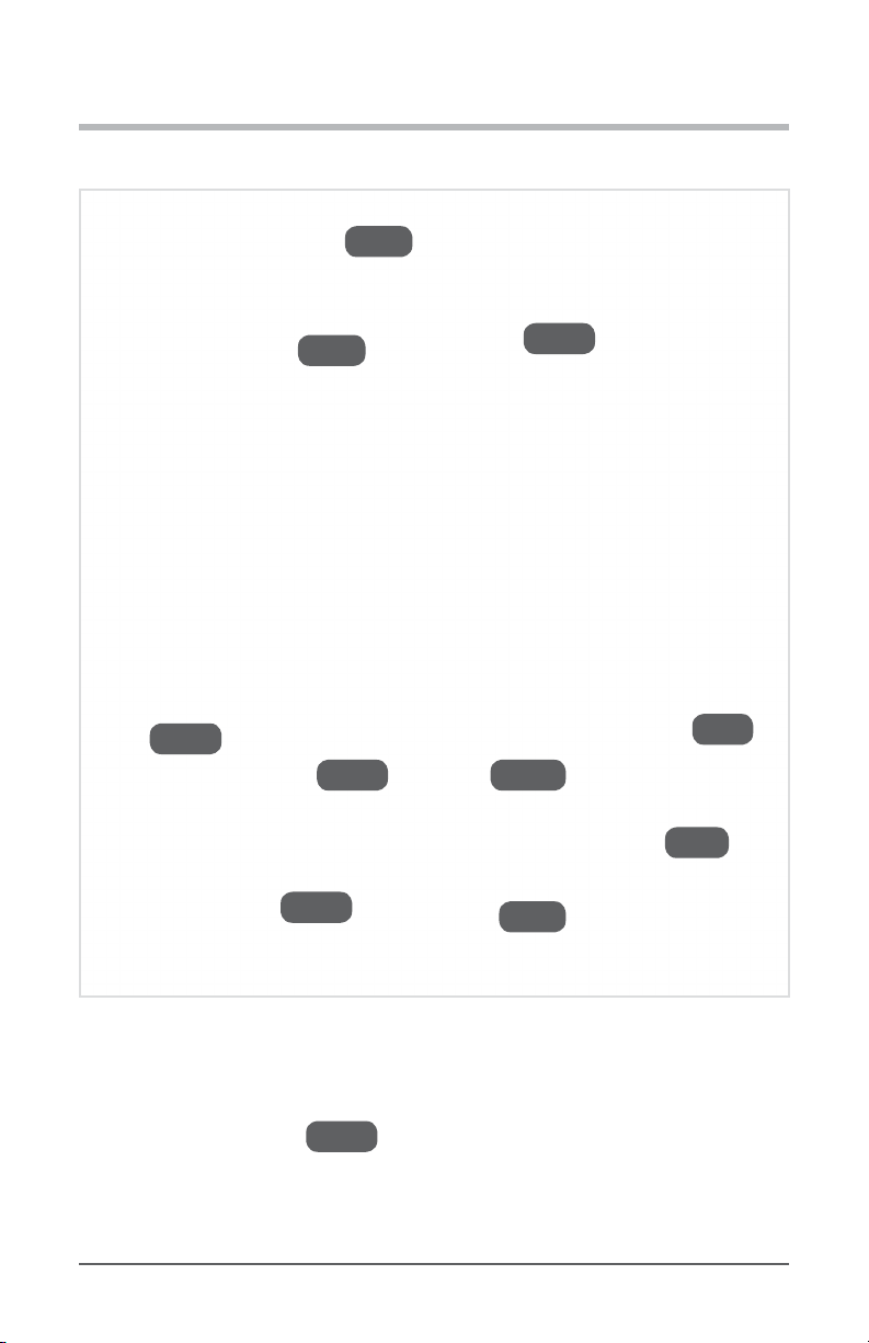
Final Check
4. Your Acc. Appliances should be connected to E 1/4 in. Brass Compression Tee,
and there should be a section of A 1/4 in. White PP Tubing running from there to
where your Drinkpod 1000 Pro Series will be located, with C
1/4 in. Quick Connect Shuto Valve attached to the other end.
P
Also, for Parallel Conguration, the section of A 1/4 in. White PP Tubing
acc.
running from your Water Source should have the Quick Connect Shuto Valve
removed from it, and be connected to the top port of the Brass Compression Tee.
If all of the above is correct, you’re ready to proceed to the next stage, “Connecting
Water Optimizer” on page 2-43. If not, review the instructions and make any
necessary corrections before proceeding. For ‘visual’ users, we’ve provided simplied
reference diagrams to double check your work.
Installing Your Water 1000 Pro Series 2-41

Installing Your Water 1000 Pro Series
ACCESSORY
APPLIANCE #1
ADAPTER
if necessary
TUBING
if necessary
BRASS
COMPRESSION
TEE
SHUTOFF
VALVE
Location for
1000 Pro Series
ACCESSORY
APPLIANCE #2
ADAPTER
if necessary
TUBING
if necessary
Diagram 2.6.6-A - Reference To Final Check For 2 Accessory Appliance Conguration
Location for
1000 Pro Series
ACCESSORY
APPLIANCE
SHUTOFF
VALVE
ADAPTER
if necessary
TUBING
if necessary
Diagram 2.6.6-B - Reference To Final Check For Parallel Conguration
Installing Your Water 1000 Pro Series 2-42
BRASS
COMPRESSION
TEE
WATER
SOURCE
TUBING

Installing Your Water 1000 Pro Series
A
Connecting Drinkpod 1000 Pro Series
Congratulations! You are now close enough to the end that you should be able to taste it.
This is the second easiest of the nal stages.
You should either have one or two water lines that end in C
1/4 in. Quick Connect Shuto Valve(s) running to where you plan on locating your new
Drinkpod 1000 Pro Series. The rst (or only) should be from your Water Source or E
1/4 in. Brass Compression Tee (for Parallel Conguration). We will refer to this line as
your Source Line. The second (if applicable) should be from your Accessory Appliance, or
1/4 in. Brass Compression Tee if you have 2 Accessory Appliances. We will refer to this
as your Accessory Line.
1. Move your new Drinkpod 1000 Pro Series to its nal location. Do not plug the power
cord in yet.
2. Cut nal short section(s) of tubing from 1/4 in. White PP Tubing to run from the
C
1/4 in. Quick Connect Shuto Valve(s) to your Drinkpod 1000 Pro Series’s ports.
Be sure to include enough additional length to allow you to pull your 1000 Pro Series
away from the wall (for maintenance).
3. Now connect the section(s) of A 1/4 in. White PP Tubing to the open port(s) on
the C 1/4 in. Quick Connect Shuto Valve(s) of your Source Line and
Accessory Line (if applicable). Use the standard quick connect method to attach them.
Diagram 2.7.3 Connect Tubing To Shuto Valve
Installing Your Water 1000 Pro Series 2-43

Installing Your Water 1000 Pro Series
4. Next, remove the Input Port Plug from Source Input Port using the standard quick
connect detach method, as shown below (but with appliance port and plug, rather than
shuto valve and tubing).
Diagram 2.7.4 - How To Detach Quick Connect Tubing
5. Connect the open end of the section of A 1/4 in. White PP Tubing connected to
your water source to the Source Input Port on the back of your 1000 Pro Series, as
shown.
Diagram 2.7.5 - Connect Source Line To Source Input Port On Your Water 1000 Pro Series
Installing Your Water 1000 Pro Series 2-44

Installing Your Water 1000 Pro Series
6. If you’ve connected accessory appliances, use the same method from Step #4 to
remove Acc. Output Port Plug from Accessory Output Port on the back of your
Drinkpod 1000 Pro Series. If you don’t have any accessory appliances, proceed to
“Installing Filters” on page 2-46.
7. Next, connect the open end of the section of A 1/4 in. White PP Tubing connected
to your Accessory Line to the Accessory Output Port on the back of your
1000 Pro Series, the same way you did with the Source Line in Step #5.
8. Ensure both C 1/4 in. Quick Connect Shuto Valve(s) are closed as shown below,
then procced to “Installing Filters” on page 2-46.
Diagram 2.7.8 - Ensure Valve Is Closed
Installing Your Water 1000 Pro Series 2-45

Installing Your Water 1000 Pro Series
Installing Filters
Please note, only the INTERNAL lter (ULTRA+3 ) is required for the appliance to
function. However, this special edition comes with an additional EXTERNAL lter
(Particle) that will, in many cases, extend your primary lters life. We recommend
installing it from the beginning, but can be connected later, as necessary.
Use of the external lter could result in a reduced ow rate, based on your water
pressure, and the distance between your Drinkpod 1000 Pro Series and water
source.
1. Remove the magnetic lter door from the internal lter compartment.
Diagram 2.8.1 - Remove Magnetic Filter Door To Reveal EZ-twist Mount In Water 1000 Pro Series
2. Grab the ULTRA+3 Hybrid Scrub you ushed earlier (to install in the internal slot).
Installing Your Water 1000 Pro Series 2-46

Installing Your Water 1000 Pro Series
Remove the bags and top cap.
3. To install, hold the ULTRA+3 Hybrid Scrub in your hand so that its name on the label
is rotated roughly 90 degrees counterclockwise. This (or rotated 180 degrees further) is
the direction each lter should be rotated before beginning to insert it into the mounting
bracket.
Diagram 2.8.3 - Hold Filter Rotated 90 Degrees CCW
4. Next, with your other hand, grab and pivot the lter mount up/back. Continue to hold
and brace it for the next step.
5. Now, insert the lter up into the bracket while twisting clockwise 90 degrees, until you
feel it lock into place.
6. Release the lter and bracket, letting the latter pivot back down to its normal position,
and reattach the magnetic lter door.
Optional - Expanding Purication Capabilities
7. First, grab part H Expansion Filter Mounting Bracket, and slide it up into the upper
the rear lter mounting slots on the back of your Drinkpod 1000 Pro Series.
Installing Your Water 1000 Pro Series 2-47

Installing Your Water 1000 Pro Series
Diagram 2.8.7 - Insert Expansion Filter Mounting Bracket
8. Pivot the bracket back so that the lower ‘arms’ insert into the lower mounting slots.
Diagram 2.8.8 - Pivot Expansion Filter Mounting Bracket Back/Down
9. Slide the bracket down till it sits rmly in place. You may need to lift the tab on the lower
end of the bracket outward to allow the bracket to slide all of the way down.
Installing Your Water 1000 Pro Series 2-48

Installing Your Water 1000 Pro Series
Diagram 2.8.9 - Slide Expansion Filter Mounting Bracket Firmly Into Place
10. Next, slide part I Expansion Filter EZ-Twist Mount all the way down into part
H
Expansion Filter Mounting Bracket.
Diagram 2.8.10 - Slide Expansion Filter EZ-twist Mount Into Bracket
11. Connect one end of part K Expansion Filter Appliance Line into the RIGHT port
of part I Expansion Filter EZ-Twist Mount (labeled OUT) using the usual steps for
Quick Connect ttings.
Installing Your Water 1000 Pro Series 2-49

Installing Your Water 1000 Pro Series
Diagram 2.8.11 - Connect Expansion Filter Appliance Line To Mount
12. Remove the plug from the Source/Input Port at the back of your 1000 Pro Series.
Diagram 2.8.12 - Remove Plug From Source/Input Port
13. Now, connect the other end of K Expansion Filter Appliance Line into the RIGHT
Source/Input Port at the rear of your Drinkpod 1000 Pro Series.
Installing Your Water 1000 Pro Series 2-50

Installing Your Water 1000 Pro Series
Diagram 2.8.13 - Connect Expansion Filter Appliance Line To Water 1000 Pro Series Input
14. Connect the end of part J Expansion Filter Source Line with the right-angle
tting into the LEFT port of I Expansion Filter EZ-Twist Mount (labeled
IN). From now on, we will refer to this as your Source/Input Port, and the C
1/4 in. Quick Connect Shuto Valve will replace valve we previously attached to
your water source line.
Diagram 2.8.14 - Connect Expansion Filter Source Line To Mount
15. Finally, install the Particle Scrub into I Expansion Filter EZ-Twist Mount using the
Installing Your Water 1000 Pro Series 2-51

Installing Your Water 1000 Pro Series
same steps as the internal lter.
Diagram 2.8.15 - Inser Particle Filter Into Mount
16. Proceed to “Enabling Water Flow” on page 2-52. You’re almost nished!
Diagram 2.8.16 - Expansion Filter Assembly Properly Connected
Installing Your Water 1000 Pro Series 2-52

Installing Your Water 1000 Pro Series
Enabling Water Flow
This is the second to last stage of installation. In this stage, we will enable water ow at each
shuto valve, one at a time to ensure there are no leaks.
1. If it’s not already open, start by opening your Water Source Valve (the valve on your
existing water source we rst shut o).
2. If you’re using a Sink Water Source, open the valve on F
3/8 in. Sink Adapter Valve (if you haven’t already opened it). Conrm there are no
leaks.
Diagram 2.8.2 - Open Sink Adapter Valve
3. Ensure nothing is leaking between the last applicable valve above, and the shuto valve
connected to your Source Line.
4. Now open the valve on the Quick Connect Shuto Valve connected to your Source Line
and Source Input Port on your 1000 Pro Series, as shown below.
Installing Your Water 1000 Pro Series 2-53

Installing Your Water 1000 Pro Series
Diagram 2.8.4 - Open Shuto Valve
5. You should hear water running and lling the 1000 Pro Series’s tanks. Check for leaks, and
wait until the sound of water running stops.
6. Once the 1000 Pro Series is lled, plug it in, but do not ip on the power switches yet.
7. We need to ush each temperature mode. Start by ushing the Ambient Mode into
your large container for 30 seconds. Press the light blue Ambient Mode Button to begin
dispensing.
8. Now, for the best experience, we recommend ushing the full tank capacity for both the
Hot Mode and Cold Mode. For reference, the Hot Tank capacity is 0.26 gal (1 liter),
and the Cold Tank capacity is 1.1 gal (4.16 liters). For directions on how to ush your
appliance, see the included Use & Care Guide, or the Quick Start Sticker applied to
your Drinkpod 1000 Pro Series’s control panel.
9. If you haven’t connected any accessory appliances to your new
Drinkpod 1000 Pro Series, you are nished!!! You can now proceed to power on your
1000 Pro Series (see Use & Care Guide for instructions).
10. If you have connected accessory appliances, you can now open the C
1/4 in. Quick Connect Shuto Valve(s) connected to your Accessory Line. Water
should now start owing into your accessory appliances. Check the lines, valve, and
Installing Your Water 1000 Pro Series 2-54

Installing Your Water 1000 Pro Series
appliances for leaks.
Diagram 2.8.11 - Open Shuto Valve On Accessory Line
11. Once you here the water stop owing, you can plug your accessory appliances back in
and power them on. If possible, ush water through each for 1 minute.
12. Congratulations! You have reached the end. You may now proceed to power on your
1000 Pro Series (see Use & Care Guide for instructions).
Installing Your Water 1000 Pro Series 2-55

APPENDICES
Appendix A - Water Sources
Accessory Water Line Source - Wall Mounted
Shuto water by turning valve handle clockwise (usually 90 degrees).
Disconnect water line by unscrewing compression bolt counterclockwise.
Connect new water line with either...
Valve Handle
Valve
APPENDICES 2-56
Hose Compression Nut
Water Line Hose

APPENDICES
Accessory Water Line Source - Floor Mounted
1. Shuto water by turning valve handle clockwise (usually 90 degrees).
2. Disconnect water line by unscrewing compression bolt counterclockwise.
3. Connect new water line with either...
Hose Compression Nut
Water Line Hose
Valve Handle
Valve
APPENDICES 2-57

APPENDICES
Accessory Water Line Source - Unmounted
1. Shuto water by turning valve handle clockwise (usually 90 degrees).
2. Disconnect water line by unscrewing compression bolt counterclockwise.
Hose Compression Nut
Water Line Hose
Valve Handle
Valve
Feed Line
APPENDICES 2-58

APPENDICES
Faucet Cold Water Line Source
1. Shuto water by turning KS-F valve handle clockwise until it stops.
2. Disconnect water line by unscrewing the compression bolt on the end KS-G connected
to KS-F counterclockwise.
KS-E
KS-A
KS-B
KS-C KS-G
KS-D
KS-H
KS-I
KS-J
KS-F
KS-A:
KS-B:
KS-C:
Left Drain
Hot Faucet Handle
Hot Water Feed Line
APPENDICES 2-59

APPENDICES
KS-D:
KS-E:
KS-F:
KS-G:
KS-H:
KS-I:
KS-J:
Hot Water Shuto Valve
Faucet
Cold Water Shuto Valve
Cold Water Feed Line
Cold Faucet Handle
Garbage Disposal
Right Drain
APPENDICES 2-60

APPENDICES
Appendix B - Component Connections
¼ in. Compression Hose Types
¼ in. Compression (Plastic Tubing)
APPENDICES 2-61

APPENDICES
APPENDICES 2-62
¼ in. Value Ice Maker Hose

APPENDICES
¼ in. Premium Ice Maker Hose / Appliance Integrated Hose
APPENDICES 2-63

NOTES
NOTES 2-64

NOTES
NOTES 2-65
 Loading...