

Page 1
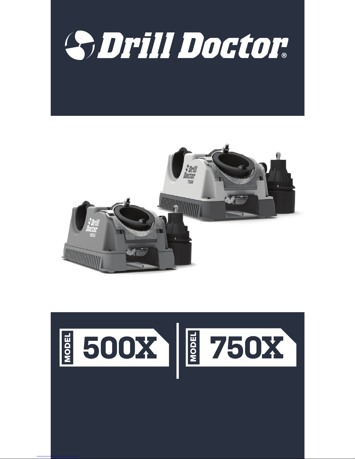
THE DRILL BIT SHARPENER
USER GUIDE
GET SHARP BACK TO WORK
AND GET
⚠ Caution!
To reduce risk of injury, the user must read and understand this instruction
manual before using product. Save these instructions for future reference.
Page 2

Drill Doctor® Drill Bit Sharpener
Class I - Consumer Product DD500X and DD750X
Transportable motor-operated electric drill bit sharpener
Manufactured by Darex, LLC
Maker of Drill Doctor®, Work Sharp®, Work Sharp Culinary®
and DAREX®
Designed, constructed and certied in accordance with:
IEC 61029-1: 1990 First Edition
EN 61029-1:2009+A11:2010
EN ISO 12100:2010
Additionally in compliance with the applicable
requirements of the following Directives and Standards:
EC Machinery Directive (2006/42/EC)
EC Electromagnetic Compatibility Directive (2004/108/EC)
DC DMF (Dimethylfumarate) Regulation (2009/25/EC)
RoHS2 Directive 2011/65/EC
Page 3

www.drilldoctor.com 3
Thank you, for purchasing a Drill Doctor
®
. It is sure to
become a valuable tool because you will always have
sharp drill bits before a project, during a project, and after
a project.
As president of this company, I am very proud of the
quality of our products—and I am equally proud of
the great people at Darex® who design and produce
them. If you have questions or need help with your Drill
Doctor®, please contact us and one of our customer
representatives will be there to help. We support what we
build!
This User’s Guide will help you learn to operate your Drill
Doctor quickly & easily. Please visit our website at
www.drilldoctor.com to:
• View instructional videos
• Submit your warranty registration
• Review FAQs
• Contact our service department
Again, thank you for buying a Drill Doctor®.
Now go enjoy its convenience and quality.
Matthew Bernard
President, Darex
®
Page 4

www.drilldoctor.com4
English ................................................................................................ 4
General Safety Rules ....................................................................... 5
Getting to Know Your Drill Doctor
®
...................................14
Identifying Basic Drill Bits ........................................................15
Anatomy of a Drill Bit ................................................................15
The Drill Doctor® Sharpening Process ...............................15
Choosing Your Drill Bit Point Angle on the
Model DD500X ..........................................................................16
Model DD750X ..........................................................................17
Aligning the Drill Bit ..................................................................17
Sharpening Drill Bits .................................................................19
Identifying Correctly Sharpened Drill Bits .........................21
Split Points ....................................................................................22
Identifying Correctly Split Drill Bits ......................................24
Grit Tube ........................................................................................25
Sharpening Bits of Dierent Lengths, Diameters,
and Types ................................................................................25
Masonry Drill Bits ....................................................................26
Adjusting Chisel and Relief Angles .....................................27
Adjusting the Material Take-O (DD750X only) ............. 29
Questions and Answers ...........................................................29
Drill Doctor
®
Maintenance ....................................................32
Parts and Accessories ...............................................................35
Warranty ........................................................................................36
Original Instructions
English
Contents
Page 5

www.drilldoctor.com 5
⚠WARNING! When using electric tools, basic safety
precautions should always be followed to reduce the
risk of fire, electric shock and personal injury. Read all
these instructions before attempting to operate this
product and save these instructions.
⚠WARNING! CHOKING HAZARD!
Small Parts – Not for children under 3-yrs.
Installation/Assembly
The Drill Doctor ® is completely assembled.
Carefully unpack the power tool and set it on the table. Check to
see that no damage has occurred in shipment. Check all packing
materials to be sure that all parts are present. See “Getting to
know your Drill Doctor
®
” for a parts indentication diagram.
⚠WARNING! Connect to properly wired (115V or 230V, as
applicable) outlet, or electrical shock may occur.
1. Work Area Safety:
a) Keep work area clean and well lit. Cluttered or dark areas
invite accidents.
b) Do not operate power tools in explosive atmospheres,
such as in the presence of flammable liquids, gases or
dust. Power tools create sparks which may ignite the dust or
fumes.
c) Keep children and bystanders away while operating a
power tool. Distractions can cause you to lose control. Do
not let persons not involved in the work touch the tool or
power cord.
d) Make workshop kid proof with padlocks, master switches
or by removing starter keys.
e) Securely place this tool on your workbench during use.
2. Electrical Safety:
⚠ DANGER! Electrical shock can kill! Read,
understand and follow ALL safety instructions.
⚠ WARNING! Do not expose power tools to rain
or wet conditions. Water entering a power tool will
increase the risk of electric shock.
General Safety Rules
Page 6

www.drilldoctor.com6
a) Power tool plugs must match the outlet. Never modify the
plug in any way. Do not use any adapter plugs with earthed
(grounded) power tools. Unmodified plugs and matching
outlets will reduce risk of electric shock.
b) Avoid body contact with earthed or grounded surfaces,
such as pipes, radiators, ranges and refrigerators. There is
an increased risk of electric shock if your body is earthed or
grounded.
c) Do not abuse the cord. Never use the cord for carrying,
pulling or unplugging the power tool. Never yank the cord
to disconnect it from the socket. Keep cord away from heat,
oil, sharp edges or moving parts. Damaged or entangled
cords increase the risk of electric shock.
d) Use proper extension cord. Use only 3-wire extension
cords that have 3-prong plugs and 3-pole receptacles that
accept the power tool’s plug. Make sure your extension cord
is in good condition. When using an extension cord, be sure
to use one heavy enough to carry the current your product
will draw. Use marked outdoor extension cord leads when
the tool is used outdoors.
e) Disconnect tools. Always disconnect your power tool when
cleaning, inspecting, and changing accessories. When not in
use, disconnect from the power supply. Never touch internal
parts of the sharpener when it is turned on or plugged in.
The rotating diamond wheel can result in injury.
f) Grounding instructions. In the event of a malfunction or
breakdown, grounding provides a path of least resistance for
electric current to reduce risk of electric shock. This power
tool is equipped with an electric cord having an equipmentgrounding conductor and grounding plug. Do not modify
the plug provided. The plug must be plugged into a matching
outlet that is properly installed and grounded in accordance
with all codes and ordinances. Improper connection of
the equipment-grounding conductor can result in a risk of
electric shock. The conductor with insulation having an outer
surface that is green with or without yellow stripes is the
equipment-grounding conductor. If repair or replacement
of the electric cord or plug is necessary, do not connect
the equipment-grounding conductor to the live terminal.
Check with a qualified electrician or service personnel if the
grounding instructions are not completely understood, or if
in doubt as to whether the tool is properly grounded. Repair
or replace damaged or worn cord immediately.
g) When operating a power tool outdoors, use an extension
cord suitable for outdoor use. Use of a cord suitable for
outdoor use reduces the risk of electric shock.
Page 7
www.drilldoctor.com 7
Fig. A
Fig. C
Cover of Grounded
Outlet Box
Cover of Grounded
Outlet Box
Grounding Pin
Grounding Means
Metal Screw
Adapter
Fig. D
Fig. B
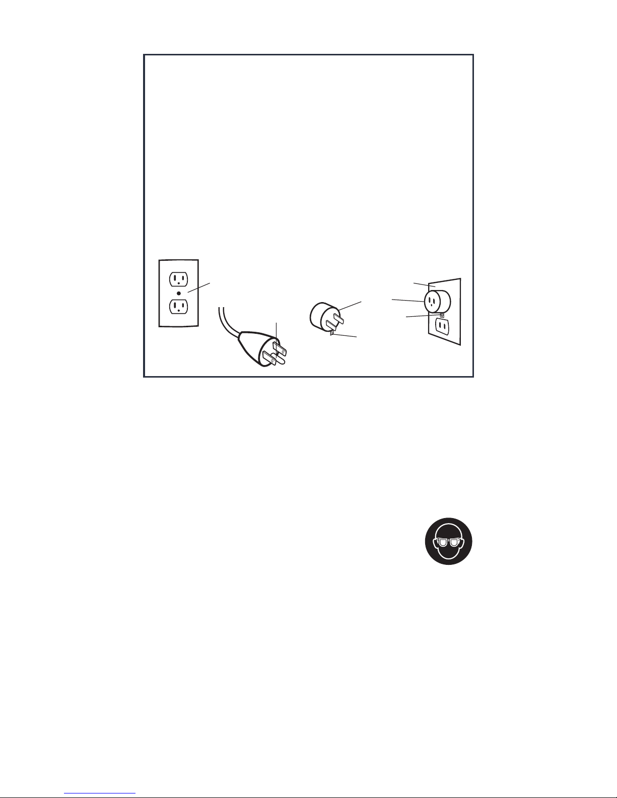
USA Only
This tool is intended for use on a circuit that has an outlet
that looks like the one illustrated in Fig. A. It has a grounding
plug that looks like the one in Fig. B. A temporary adapter,
which looks like the adapter illustrated in Fig. C & Fig. D, may
be used to connect this plug to a 2-pole receptacle as shown
in Fig. D if a properly grounded outlet is not available. The
temporary adapter should be used only until a properly
grounded outlet can be installed by a qualified electrician.
The green-colored rigid ear, lug, and the like, extending
from the adapter must be connected to a permanent
ground such as a properly grounded outlet box.
3. Personal Safety:
Sharpening operations can create hot sparks and metal debris,
loud noises and dust.
a) Stay alert - watch what you are doing and use common
sense when operating a power tool. Do not use a power
tool while you are tired or under the influence of drugs,
alcohol or medication. A moment of inattention while
operating power tools may result in serious
personal injury.
b) Use personal protective equipment (PPE).
Always wear eye protection. Protective
equipment such as dust mask, non-skid safety
shoes, hard hat or hearing protection used for appropriate
conditions will reduce personal injuries.
c) Use ear protection during use. Drill Doctor® unit can
generate in excess of 85 dB(A) noise emissions when in
operation.
d) Prevent unintentional starting. Ensure the switch is in
the off-position before connecting to power source and/
or battery pack, and when picking up or carrying the tool.
Carrying power tools with your finger on the switch, or
energizing power tools that have the switch on invites
accidents.
Page 8

www.drilldoctor.com8
e) Remove any adjusting key or wrench before turning the
power tool on. A wrench or a key left attached to a rotating
part of the power tool may result in personal injury.
f) Do not overreach. Keep proper footing and balance at
all times. This enables better control of the power tool in
unexpected situations. Nonslip footwear is recommended.
g) Dress properly. Wear closed, non-flammable protective
clothing. Do not wear loose clothing or jewelry. Keep your
hair, clothing and gloves away from moving parts. Loose
clothes, jewelry or long hair can be caught in moving parts.
h) Secure Work. Use clamps or a vise to hold work when
practical. It’s safer than using your hand and it frees both
hands to operate tool.
4. Power Tool Use and Care
⚠ WARNING! Use recommended accessories. Use the power
tool, accessories, abrasives, and tool bits etc., in accordance
with these instructions, taking into account the working
conditions and the work to be performed. Use of the power tool
for operations different from those intended could result in a
hazardous situation.
⚠ CAUTION! Keep power tools and work space clean for
best performance and safety. Do not let sharpening debris
accumulate on, in, or around the tool. Accumulated fine metal
sharpening debris can be very hot and may present a fire danger
if the machine or your workspace is not properly cleaned and
maintained. Accumulated sharpening debris can also degrade the
life of the tool and cause premature wear on some components. If
sharpening debris has accumulated, do not immediately throw it
into a trash receptacle without ensuring the debris is completely
cool and free of heat. Improperly disposing of the accumulated
sharpening debris may present a fire risk. Do not collect the
sharpening debris during sharpening. This increases the risk of
heat build-up in the debris and the potential for fire.
a) Do not force the power tool or attachment. Use the
correct power tool for your application. Do not force small
tools to do the job of a heavy duty tool. The correct power
tool will do the job better and safer at the rate for which it is
designed.
b) Use the right tool. Do not force tool or attachment to do a
job for which it is not designed.
c) Do not use the power tool if the switch does not turn it
on or off. Any power tool that cannot be controlled with the
switch is dangerous and must be repaired.
d) Never leave tool running unattended – Turn power off.
Do not leave the tool until it comes to a complete stop.
Page 9

www.drilldoctor.com 9
e) Disconnect the plug from the power source and/or the
battery pack from the power tool before making any
adjustments, changing accessories, or storing power
tools. Such preventative safety measures reduce the risk of
starting the power tool accidentally.
f) Store idle power tools out of reach of children and do
not allow persons unfamiliar with the power tool or
these instructions to operate the power tool. Power tools
are dangerous in the hands of untrained users.
g) Keep cutting tools sharp and clean for better and safer
performance.
h) Follow instructions for lubricating (if applicable) and for
changing accessories.
i) Maintain power tools. Check for misalignment or binding
of moving parts, breakage of parts and any other condition
that may affect the power tool’s operation. If damaged, have
the power tool repaired by an authorized service center
before use. Keep handles dry, clean and free from oil and
grease. Many accidents are caused by poorly maintained
power tools.
j) Inspect tool cord periodically and if damaged have
it repaired by an authorized service center. Inspect
extension cords periodically and repair if damaged.
k) Keep guards in place and in working order. A guard or
other part that is damaged should be properly repaired or
replaced by an authorized service center unless otherwise
indicated in the instruction manual.
l) Never stand on the power tool. Serious injury could
occur if the tool is tipped or if the sharpening edge is
unintentionally contacted.
m) Check damaged parts. Before further use of the tool,
any part that is damaged should be carefully checked to
determine that it will operate properly and perform its
intended function. Check the alignment of moving parts,
binding of moving parts, breakage of parts, mounting and
any other conditions that may affect its operation. Any
damaged part, including the switch, should be properly
repaired or replaced by an authorized service center.
n) Do not use if the grinding wheel is damaged. Use only
grinding wheels recommended by Drill Doctor
®
Page 10

www.drilldoctor.com10
5. Service
a) Have your tool serviced by a qualified repair person
using only identical replacement parts. This will ensure
that the safety of the power tool is maintained.
b) Do not dispose of electrical products with
household waste. Waste electrical products
should not be disposed of with household
waste. Please recycle where facilities exist.
Check with your local authority or retailer for
recycling advice.
Specic Safety Rules
⚠ WARNING! ALWAYS use proper safety glasses. Everyday
eyeglasses are NOT safety glasses. Also use face or dust mask if
operation is dusty. ALWAYS wear certified safety equipment:
• ANSI Z87.1 eye protections (CAN/CSA Z94.3)
• ANSI 512.6 (53.19) hearing protection
• NIO5H/OSHA respiratory protection
⚠ WARNING! Use of this tool can generate and/or disperse
dust, which may cause serious permanent respiratory or
other injury. Always use NIOSH/OSHA approved respiratory
protection appropriate for the dust exposure. Direct particles
away from face and body.
For Service in the USA, Contact:
Darex, LLC
PO Box 730
210 E Hersey St
Ashland OR 97520
Page 11
www.drilldoctor.com 11
12
12
14
0
115V
0-25
(0-7.6m)
101-200
(30.4-60.9m)
51-100
(15.2-30.4m)
26-50
(7.6-15.2m)
Volts
6
10
10 12
12
Not Recommended
Ampere Rating
Minimum Gauge Cord Sets
Total Length of Cord in Feet
Save These Instructions
Not More Than
More Than
American Wire Gauge
12 16
16
1618
1618
16
14
14
14
16
6
Motor
Be sure your power supply agrees with the nameplate marking.
115 Volts means your tool will only operate on standard 60HZ
household power. 230 Volts means your tool will only operate
on standard 50 HZ household power. Do not operate AC tools
on DC. Lower voltage will cause loss of power and can result in
overheating. Using a machine on an unmatched power source
voids your warranty.
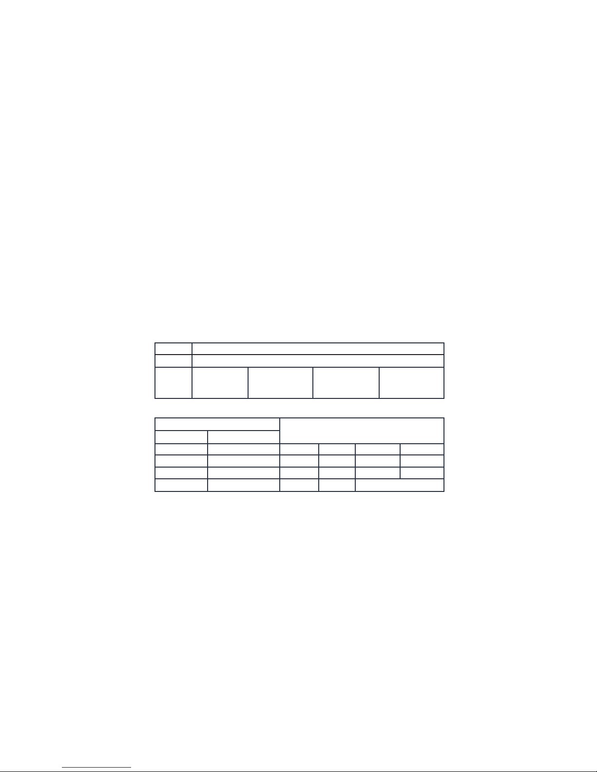
Extension Cords
Make sure your extension cord is in good condition. When using
an extension cord, be sure to use on heavy enough to carry the
current voltage resulting in loss of power and overheating. The
Drill Doctor® has a 1.75 ampere rating. The following table shows
the correct size to use depending on cord length and nameplate
ampere rating. If in doubt use the next heavier gauge. The smaller
the gauge number the heavier the cord.
Page 12
www.drilldoctor.com12
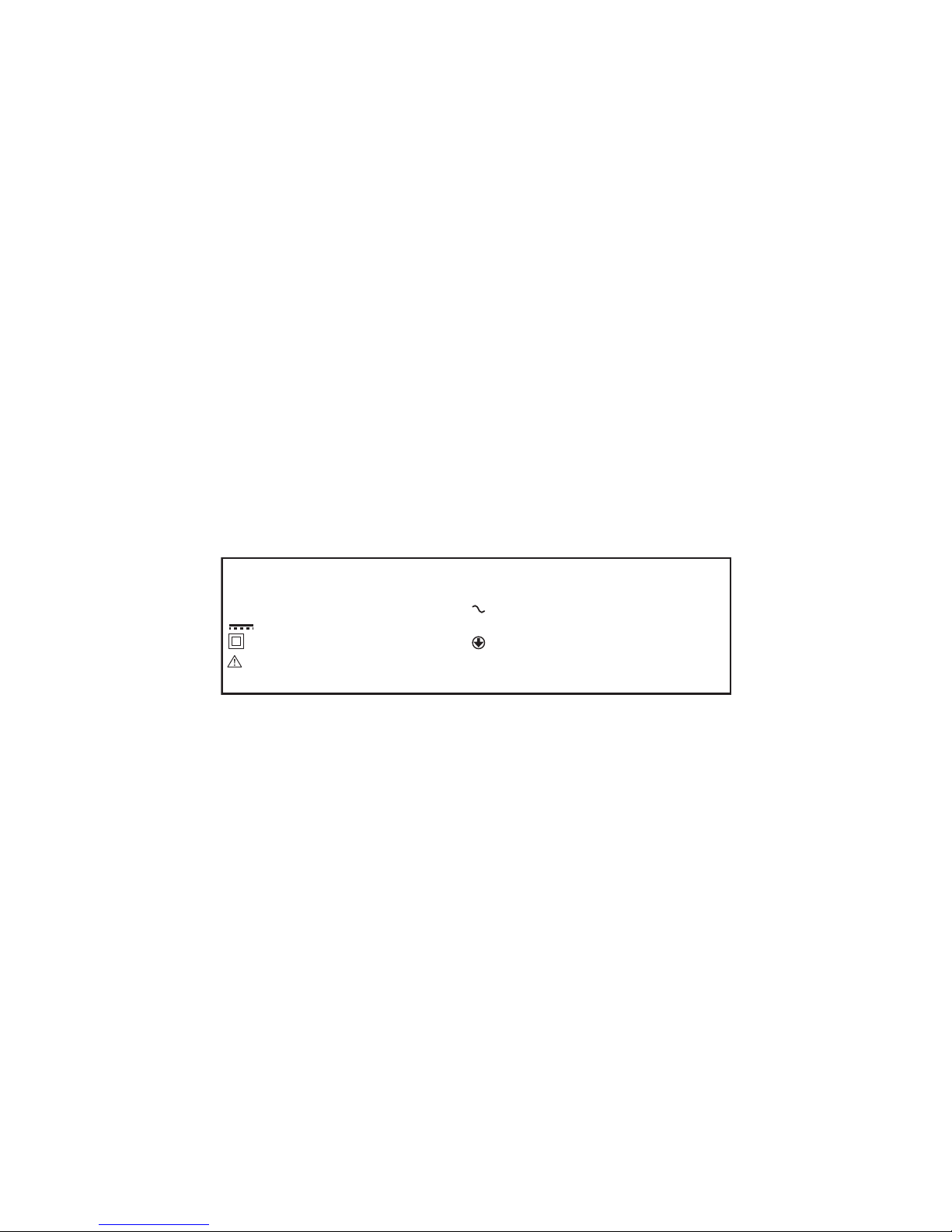
Safety Guidelines – Denitions
It is important for you to read and understand this manual. The
information it contains relates to protecting YOUR SAFETY and
PREVENTING PROBLEMS. The symbols below are used to help you
recognize this information:
⚠ DANGER! Indicates an imminently hazardous situation which,
if not avoided, will result in death or serious injury.
⚠ WARNING! Indicates a potentially hazardous situation which, if
not avoided, could result in death or serious injury.
⚠ CAUTION! Indicates a potentially hazardous situation which, if
not avoided, may result in minor or moderate injury.
CAUTION! Used without the safety alert symbol (⚠) indicates a
potentially hazardous situation which, if not avoided, may result
in property damage.
v........................
Hz.....................
Min...................
..................
.....................
.....................
volts
hertz
minutes
direct current
Class II Construction
safety alert symbol
a........................
w.......................
......................
......................
......................
rpm...................
amperes
watts
alternating current
no load speed
earthing terminal
revolutions or
reciprocations per minute
n
o
Safety Markings
Drill Bit Sharpener
15,000 RPM 110•120V - 60Hz - 1.75A max / 0.77A nom
-or- 220•230V - 50Hz - 0.88A max / 0.4A nom
AC Only
Tool mass including detachable parts.
DD500X/DD750X Mass: 2.65 lbs = 1.202 kg.
Includes:
(1) DD500X or DD750X unit, (1) User’s Guide, (1) wheel wrench
The label on your tool may include the following symbols:
Page 13

www.drilldoctor.com 13
Noise and Vibration Emissions Values
Manufacturer: Darex, LLC
Model: DD500X/DD750X
Noise Emissions:
Ld=L+K, where the maximum K = 3.0dB (per ISO 11201)
Declared value according to ISO 4817 at operator’s position:
No load Lpa = 76.9 Loaded Lpa = 89.7
Measured Value according to ISO 3744 (half-sphere):
No load Lpa = 72.0 Loaded Lpa = 75.0
Vibration Emissions:
Measured vibration during normal work 1.9m/s2; K = 1.5m/s2U
(per ISO 5349 and ISO 5349-2)
Note#1: The declared vibration total value has been measured
in accordance with a standard test method and may be used for
comparing one tool to with another.
Note #2: The declared vibration total value may also be used in a
preliminary assessment of exposure.
⚠WARNING! The vibration emission during actual use of the
power tool can differ from the declared total value depending on
the ways in which the tool is used.
⚠WARNING! Identify safety measures to protect the operator
based on an estimation of exposure in actual conditions of use.
Intended Uses
• This drill bit sharpener is designed to sharpen twist style drill bits
3/32” - 1/2”. (DD750X will sharpen up to 3/4”.)
• Sharpening drill bits in the home or small shop.
• Use in clean and dry environments
• Use with a clean power source of the correct rated voltage and cycle.
Unintended Uses (Not permissible)
• This drill bit sharpener is not intended to sharpen chisels, screw
drivers or other similar shop tools.
• This sharpener is not intended for industrial or commercial
sharpening services.
• Not for use in wet and/or hazardous environments.
• Not for use with converters or alternate power supplies.
Page 14
www.drilldoctor.com14
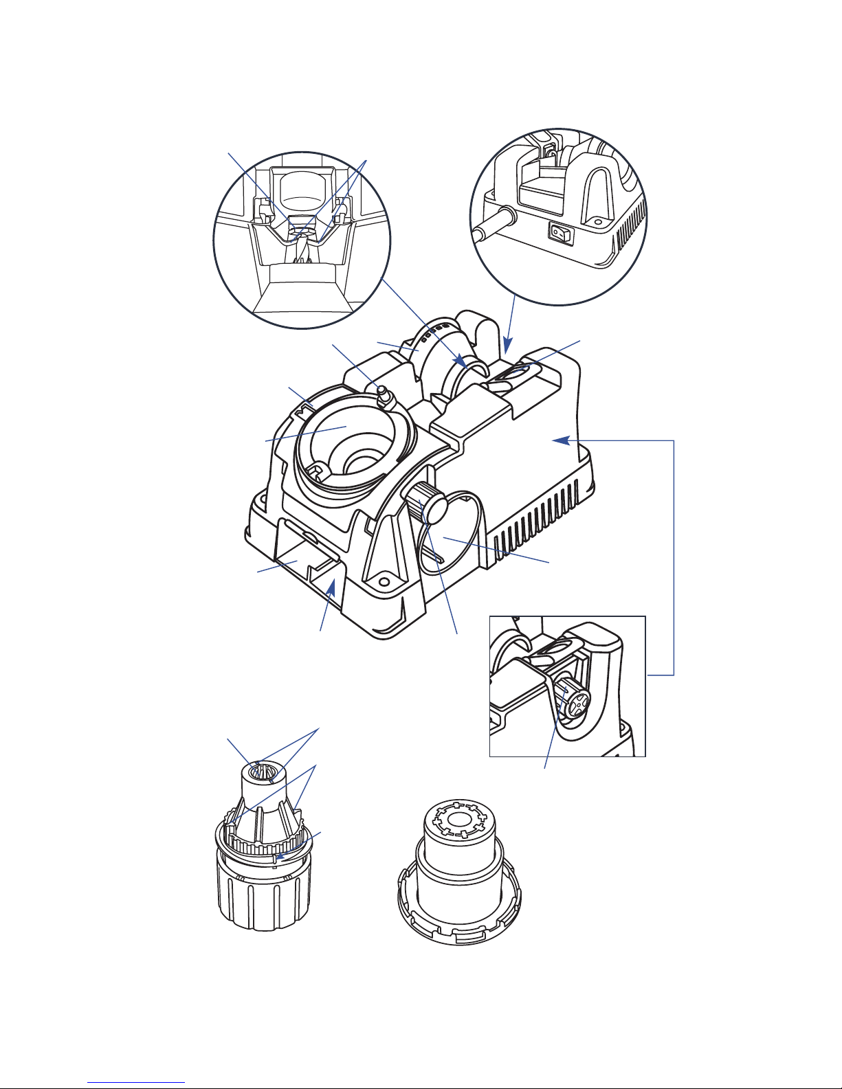
You can also watch a User Video on www.drilldoctor.com to
become a sharpening expert in minutes!
Cam Pin
Sharpening
Port
Power Switch
and Cord
Grit Tube
Chuck
Point Angle
Adjustment
Plate
Bit Clamp Arms
Drill Stop
Split Point Port
Chuck Jaws
Adjustable Material
Take-O (MTO) Knob
(750X Only)
Point Angle
Adjustment
Knob
Alignment Button
Wheel
Access
Cover
Diamond Sharpening
Wheel (Inside)
Alignment Guides
(raised ns)
(white lines)
Sharpening
Guides
Alignment
Port
On 750X
MTO is here
Masonry Bit
Alignment Mark
Getting to Know Your Drill Doctor
®
Page 15
www.drilldoctor.com 15
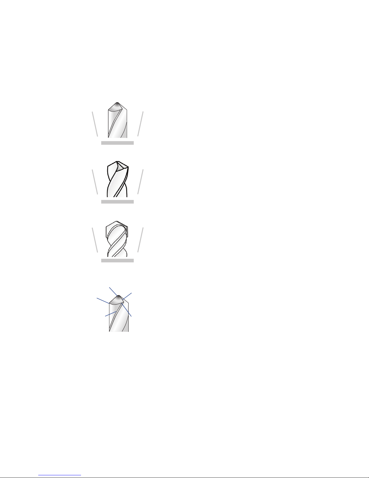
The Drill Doctor® is most efficient when used to resharpen
a drill bit’s original point angle. With its standard 180° Grit
Diamond Sharpening Wheel it will sharpen high-speed steel,
cobalt, TiN-coated, carbide and masonry drill bits. Your Drill
Doctor® has been designed to sharpen the three most common
drill bit types:
Standard Point
This general-purpose point (normally
118°) is used for drilling softer materials
like cold rolled steel, aluminum, and
wood.
Split Point
Split-point bits (normally 135°) are
generally used for drilling into harder
materials, like tempered steels, hard
alloys or hard cast materials.
Masonry Bits
Masonry bits have a carbide insert
at the point and are used for drilling
materials like cement, brick, and
ceramic.
Anatomy of a Drill Bit
When viewing a well-sharpened bit
from the side, the Heel will always be
lower than the Cutting Edge; this is
called “positive relief ”.
Chisel Tip
Cutting
Edge
Relief
Angle
Leading
Edge
Heel
The Drill Doctor® Sharpening Process
The sharpening process includes 3 easy steps:
1. Align the bit in the Chuck.
2. Sharpen the bit (until there is no more grinding noise).
3. Split the point (optional on 118°, mandatory on 135°).
Be sure to complete each step to sharpen and split a bit and
always sharpen the bit prior to splitting it.
Identifying Basic Drill Bits
Page 16
www.drilldoctor.com16
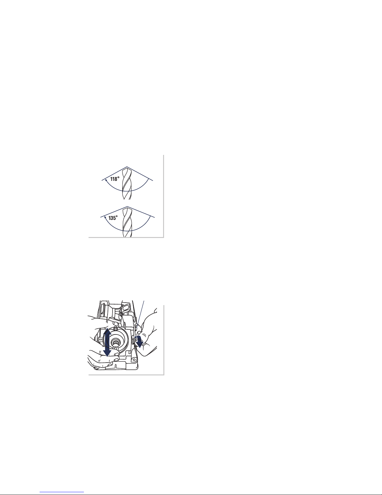
Your Drill Doctor® allows you to sharpen bits with either the
standard 118° or the atter 135° point angle. You can also adjust
the chisel and relief angle. (Refer to section “Adjust Chisel and
Relief Angles”.)
Depending on what you are drilling in, you may choose to increase
or decrease these angles.
On The Model DD500X
Check your drill bit angle
Most bits are 118° or 135°. Hold your
bit point up to the key to the left to see
which type your bit looks like. Most
wood and soft metal applications
require 118°. Harder materials such as
stainless steel and tool steel require
135°. If you are drilling contoured
materials (such a car fender), plan on
splitting the point to prevent walking
of the bit.
Choose the angle
Loosen the Point Angle Adjustment
Knob on the right side of the
Sharpening Port and slide the metal
Point Angle Adjustment Plate to
either the standard 118° or the atter
135° point angle. Then re-tighten the
Knob. The selected angle will show in
the small window on the plate.
Choosing Your Drill Bit Point Angle
Point Angle
Adjustment Knob
Page 17
www.drilldoctor.com 17
On The Model DD750X
Choose the angle
The Model DD750X has additional
advanced features that enable you
to ne-tune your bit geometry.
Loosen the Point Angle Adjustment
Knob to the right of the Sharpening
Port and slide the metal Point
Angle Adjustment Plate to
standard 118° or 135° (or anywhere
in-between, allowing you to create
the custom angle of your choice.)
Choose the point angle based on
the application (material) you’re
drilling. Then re-tighten the Knob.
Aligning the Drill Bit
Proper alignment ensures your Drill Doctor will create the correct
geometry on your bit. It also sets the drill stick-out, so that only
a small amount of material is removed during sharpening.
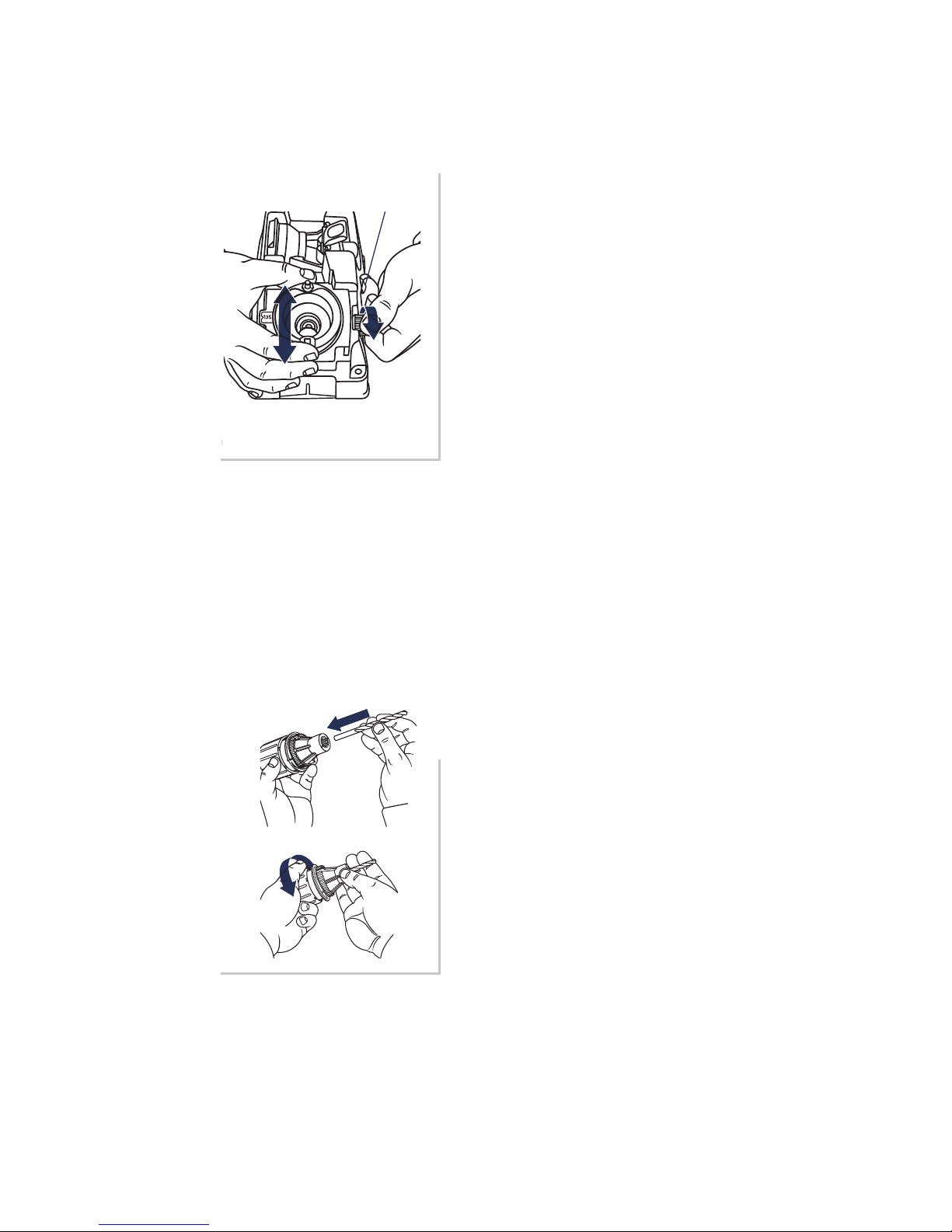
1. Insert bit in Chuck and
tighten
Insert the bit into the Chuck
and close the Jaws just to the
point where the bit slides in
and out. Do not over tighten
the Chuck; the bit needs to be
able to move in and out until
Step 4.
Model DD750X features an
adjustable Material Take-O.
Refer to section: Using the
Variable Material Take-O to
learn more.
Point Angle
Adjustment Knob
Page 18
www.drilldoctor.com18
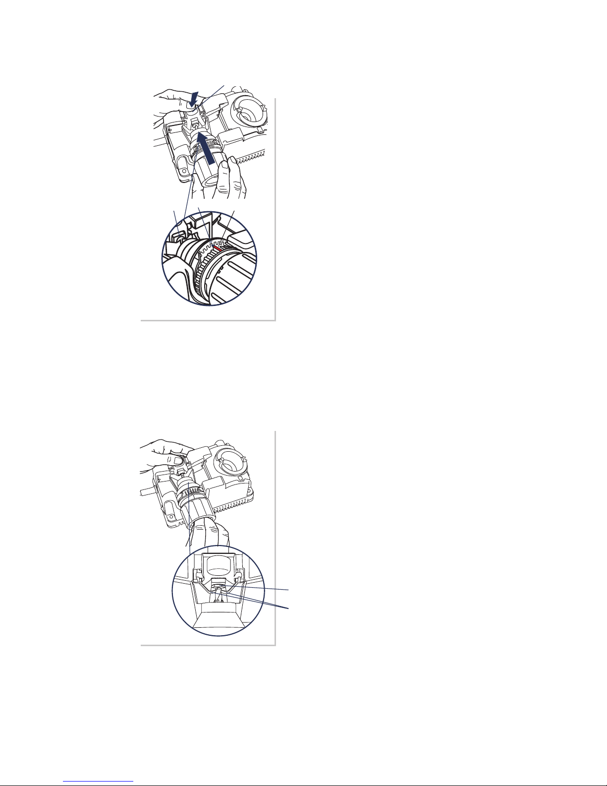
2. Insert Chuck into
Alignment Port
Press the Alignment Button down
that opens the bit clamp arms.
Insert either of the Alignment
Guides (raised ns) on the Chuck
into the 118° notch on the
Alignment Port. With the clamp
arms held open, slide the drill
bit forward until it touches the
Drill Stop. (Make sure the Chuck
is seated all the way into the
Alignment Port). Now release the
Alignment Button, releasing the
clamp arms.
When sharpening standard 118°
drill bits, align in the 118° slot.
For standard 135° drill bits, align
1-notch to the right (-) of the 118°
slot.
Alignment Button
Drill Bit
Stop
118°
Alignment
Guide
3. Adjust Bit Position
Check to ensure your bit is held in
place correctly. The Clamp Arms
should be holding the drill bit at
its narrowest spot (in the utes).
If they aren’t, turn the bit slightly
until they fall into the utes. This
is an important step to proper
alignment.
Drill Bit Stop
Bit Clamp Arms
Page 19
www.drilldoctor.com 19
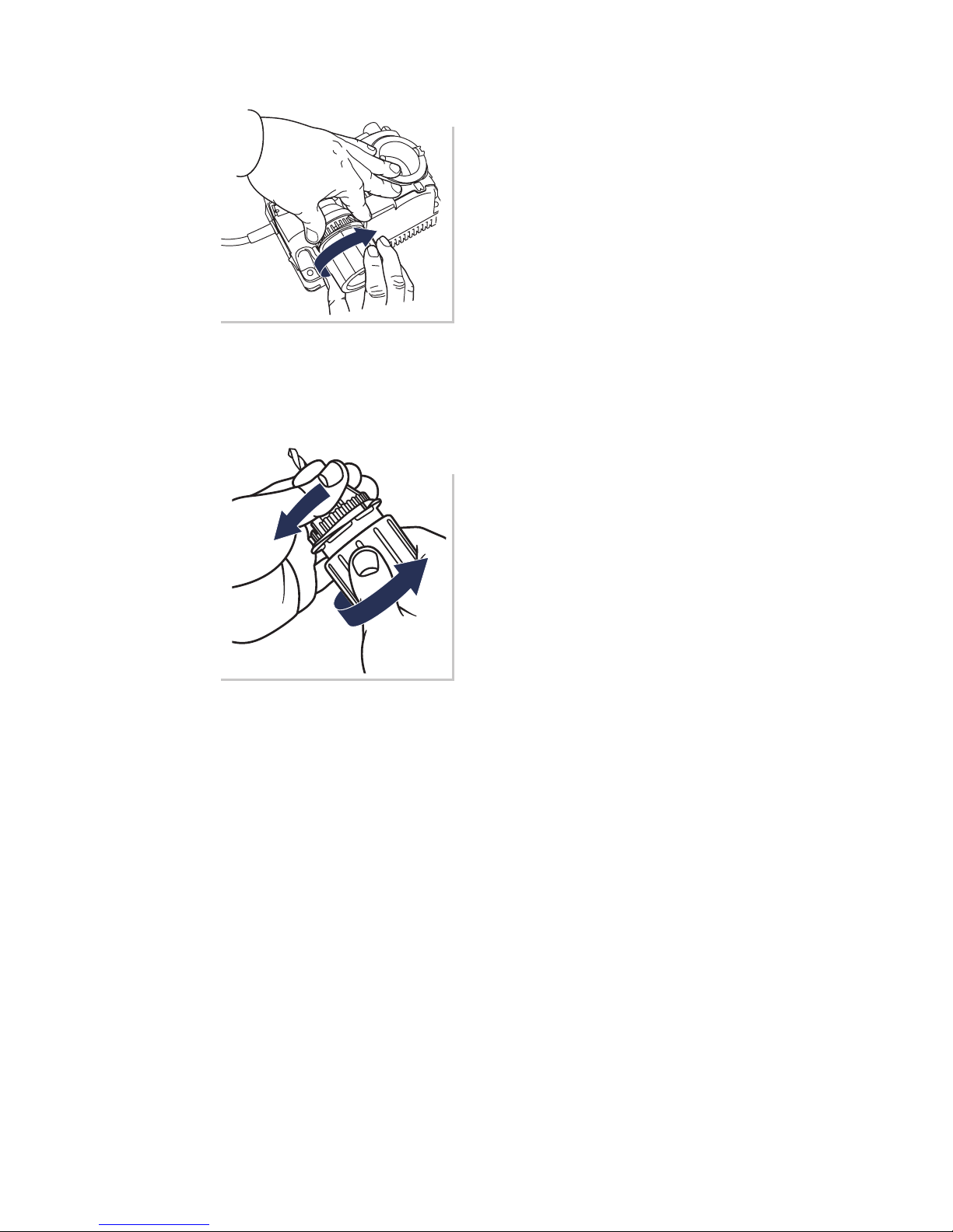
4. Lightly Tighten Chuck
Hold onto the Chuck and
tighten the Chuck Knob until it
is snug. (Avoid over-tightening
the Chuck in the Alignment
Port as this could damage the
alignment teeth in the port.)
Press the Alignment Button
and remove the Chuck from
the Alignment Port. Tighten
the Chuck once more to
ensure the bit won’t move
when you sharpen it.
You are now ready to sharpen
the drill bit!
Sharpening the Bit
Before sharpening you should know:
• Keep the Chuck in contact with the Cam Pin at all times as
you sharpen.
• Only light pressure is required.
• You will hear a grinding noise (zzzzzzzzz) as you complete
each half-turn and each side of the bit face is ground.
• The sharpening port will rock as you rotate the Chuck.
Page 20
www.drilldoctor.com20
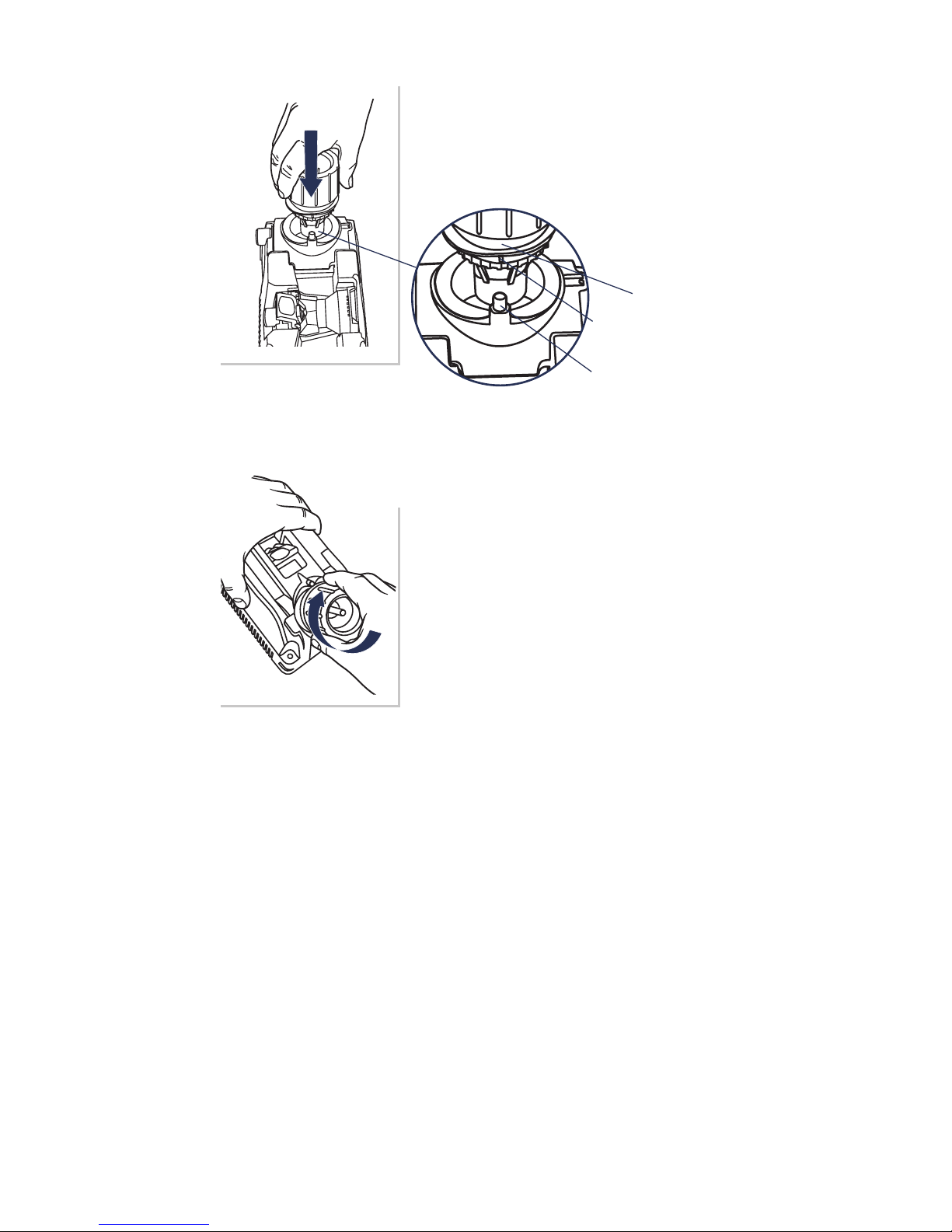
1. Sharpening Guides
Insert Chuck into Sharpening Port
with either of the Sharpening Guides
(white lines) lined up with the Cam Pin
on the machine.
2. Sharpen Your Bit
Rotate Chuck in a clockwise direction
(from white line to white line) until
there is no more grinding noise. Ensure
you are keeping Chuck up against Cam
Pin at all times. Your motion should be
smooth and even.
Dierent size drill bits may require a dierent number of rotations.
Continue to sharpen until you no longer hear grinding noise. This
will result in a Chisel Edge that is clean and straight and ensure the
entire surface from the Cutting Edge to the Heel is nely ground.
Note: If splitting your drill bit, do not remove from Chuck after
sharpening.
Cam Pin
Cam
Sharpening Guide
(white lines)
Page 21
www.drilldoctor.com 21
Identifying Correctly Sharpened Drill Bits
(and what to do with those that aren’t!)
Correctly Sharpened Bits
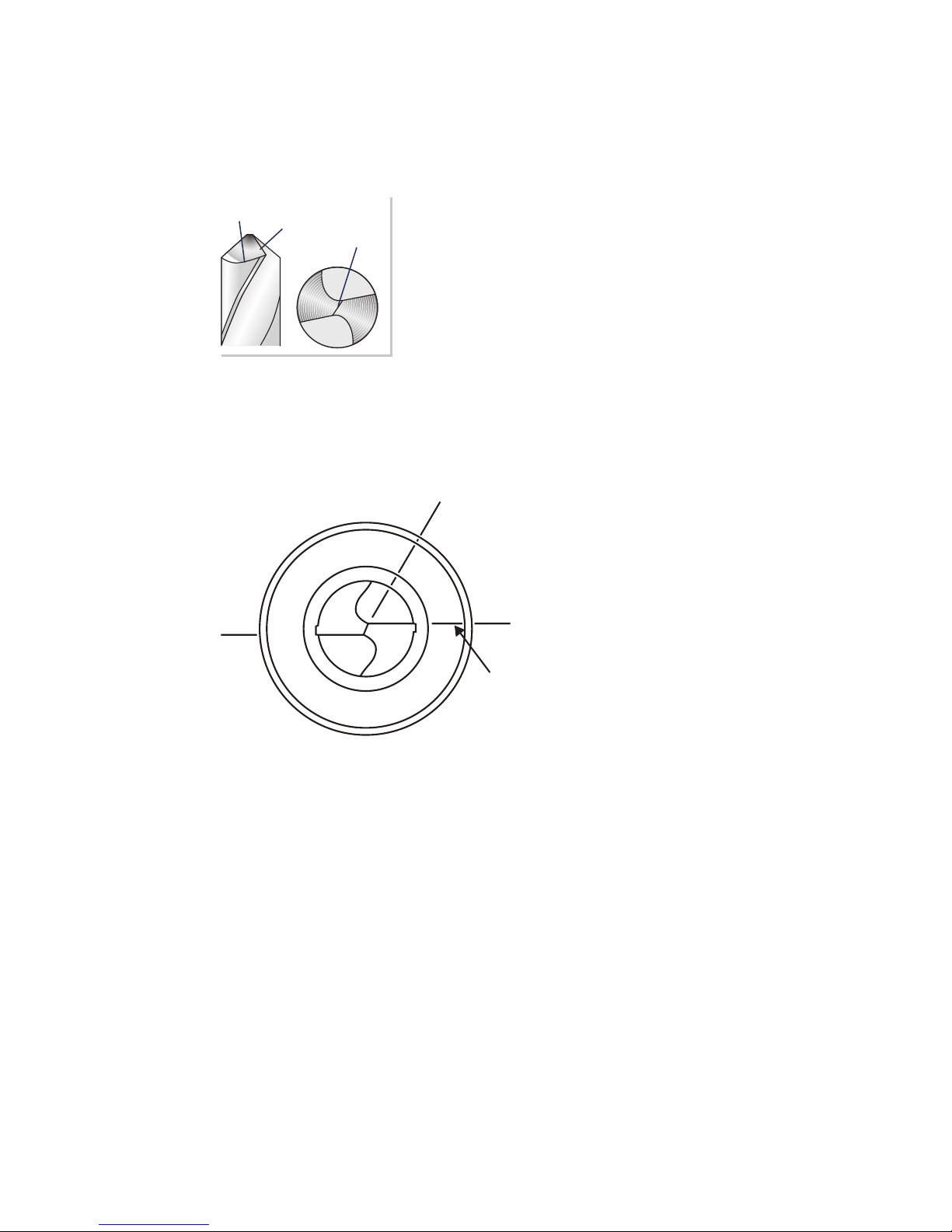
The entire surface from the Cutting Edge
to the Heel will have a nely ground
surface without indentations. The Heel
will always be lower than the Cutting
Edge (positive relief).
Once you have reached spark-out (no more grinding noise at all)
take a look at your drill bit. The chisel angle should be between
1:00 and 1:30.
*Look at the bit: Hold
the bit up and look at it
with the cutting edges in
line with the horizon (or
parallel with the 9:00 and
3:00 position imagining a
clock’s face).
Now look at the chisel.
It should be between
1:00 and 1:30. 2:00 is too
far advanced, and if the
chisel gets too close to 12:00, the relief will be negative.
Too much relief will cause an oversized hole diameter and rapid bit
wear. Too little relief will limit feed rates, slowing down the drilling
operation or in extreme cases cause the drill not to perform at all.
If chisel angle looks to be about 2 o’clock, re-align bit 1-2 ticks to
the right of the 118° mark (toward the minus sign) and re-sharpen.
If chisel angle is up to about 2:30, align 2-3 ticks towards the
minus sign.
If chisel is about 12:45,
it’s at the low end of chisel & relief, re-align bit
1 tick to the left of the 118° mark (toward the plus sign) and re-sharpen.
Heel
Cutting
Edge
Chisel
Tip
9:00
3:00
1:00
scribe
line
Page 22
www.drilldoctor.com22
Split Points
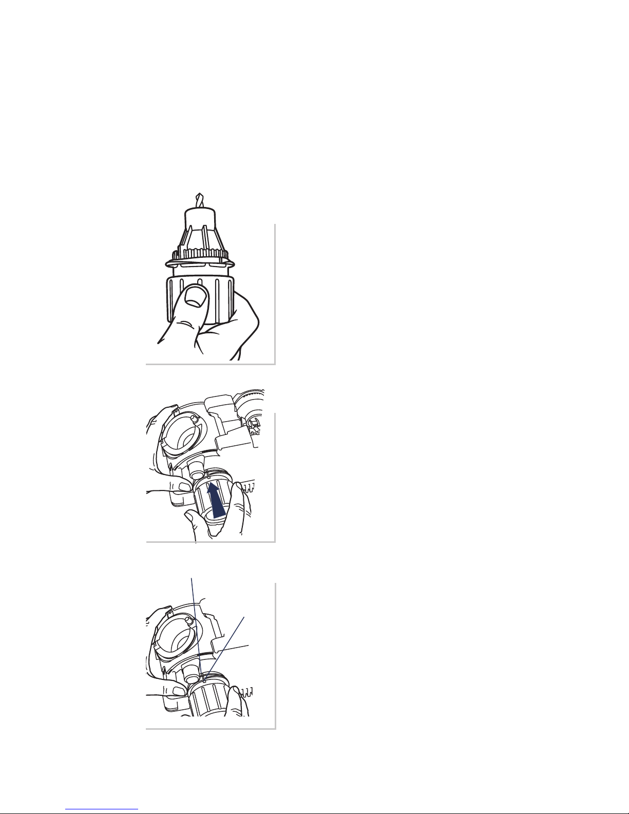
Split point drill bits prevent “walking” on the material before they
begin to cut. This feature is described as self-centering. The need
to center punch is eectively eliminated.
Split point drill bits have secondary cutting lips along the chisel
edge. Up to 70% less thrust is required to drill a hole (when
compared to a non-split or conventional point.)
1. Splitting the Point
Leave bit in Chuck after
sharpening
Always align and sharpen a bit
before splitting it. To split the point,
do not remove the bit from the
Chuck after sharpening.
2. Align Guides
Remove the Grit Tube.
Line up one of the Chuck’s
Sharpening Guides (white lines)
with the Splitting Guide on the
Splitting Port.
3. Split the point
Press Chuck slowly and rmly into
the Splitting Port. Remove the
Chuck, rotate one-half turn, and
repeat.
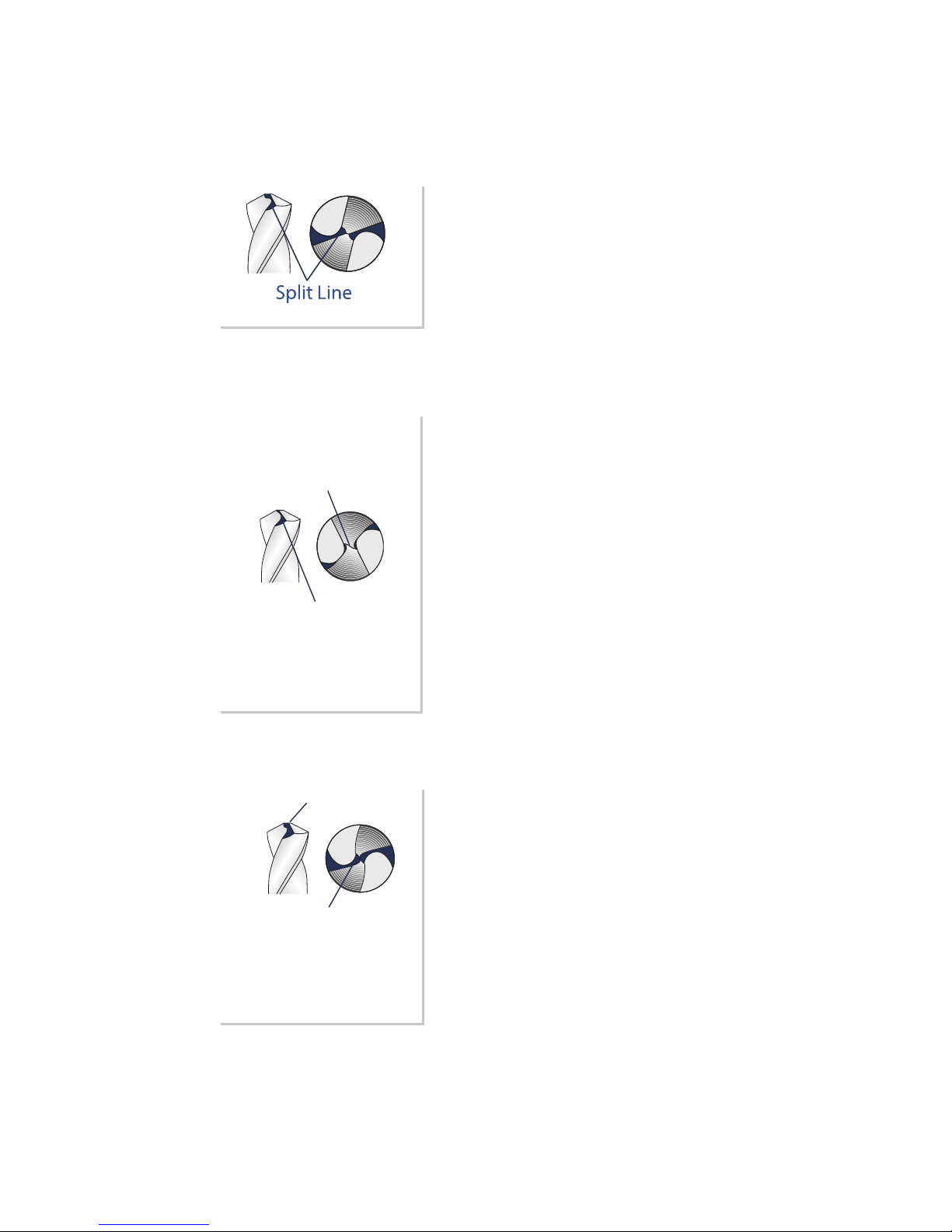
Check the tip of the bit carefully to
determine that both sides of the
bit are split equally. Compare it to
the following illustrations. If it does
not match, study the information
below.
Splitting Guide
Sharpening
Guide
Page 23
www.drilldoctor.com 23
Identifying Correctly Split Drill Bits
(And what to do with those that are
Correctly Split
Solution
Split lines are nearly straight
across.
Oversplit
Solution
Reinsert the chucked bit into
the Sharpening Port and
sharpen until the split tip looks
like the correctly split bit above,
checking every few rotations.
Undersplit
Solution
More grinding is needed for
larger drill bits. If one side of
the bit is under split, insert
the Chuck into the Splitting
Port again and split both sides.
Repeat until the split sides are
equal and look like the correctly
split bit shown above.
Split lines do not
meet in the center but
Chisel Edge remains.
Not enough material
has been removed
from the Heel of the
drill bit.
Too much material
removed.
Split lines are joined in
the center and Chisel
edge has been removed.
Page 24
www.drilldoctor.com24
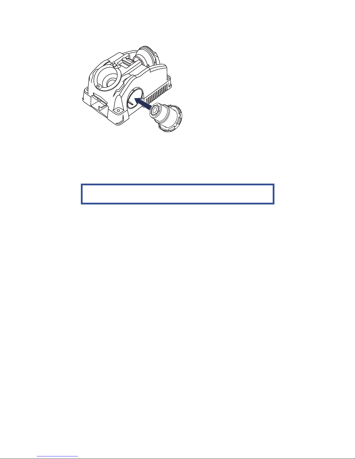
Grit Tube Attachment
The Grit Tube attachment is
designed to keep any sparks
caused by sharpening safely
inside the machine and
away from you. In addition,
the Grit Tube reduces the
sharpening dust in the air
and on your workbench.
Simply insert the Grit Tube
into the Splitting Port of
your Drill Doctor when
sharpening. It will catch the grit that is formed from the sharpening
process. Clean the inside of your Drill Doctor and the Grit Tube on
a regular schedule. The grit tube is designed to accept a standard
1” shop vacuum for extended periods of sharpening.
Never clean with an air compressor, it may damage the
machine. Use a brush or vacuum.
Sharpening Bits of Dierent Lengths, Diameters,
and Types
Dierent size drill bits may require a dierent number of rotations.
Continue to sharpen until you no longer hear grinding noise.
Large Drill Bits
The Model DD500X sharpens bits from 3/32” to 1/2”. You can also
purchase a Large Bit Chuck that sharpens bits up to 3/4”. The
Model DD750X comes equipped with that Large-Bit Chuck. It
sharpens bits from 3/32” to 3/4”.
Large bits are sharpened just like any other bit.
It is important to sharpen these bits so that the entire face of
the drill bit is sharpened. A large bit requires more half-turns to
sharpen it. It may take two or three complete sharpenings (repeat
all steps) to resharpen a very dull or chipped large drill bit.
Using an optional 100-grit coarse wheel can speed up the process.
Page 25
www.drilldoctor.com 25
Short Drill Bits & Bits Smaller than 1/8”
Sharpen the small bit as usual, but use very light pressure and
an even number of turns. The bit should only briey contact the
wheel.
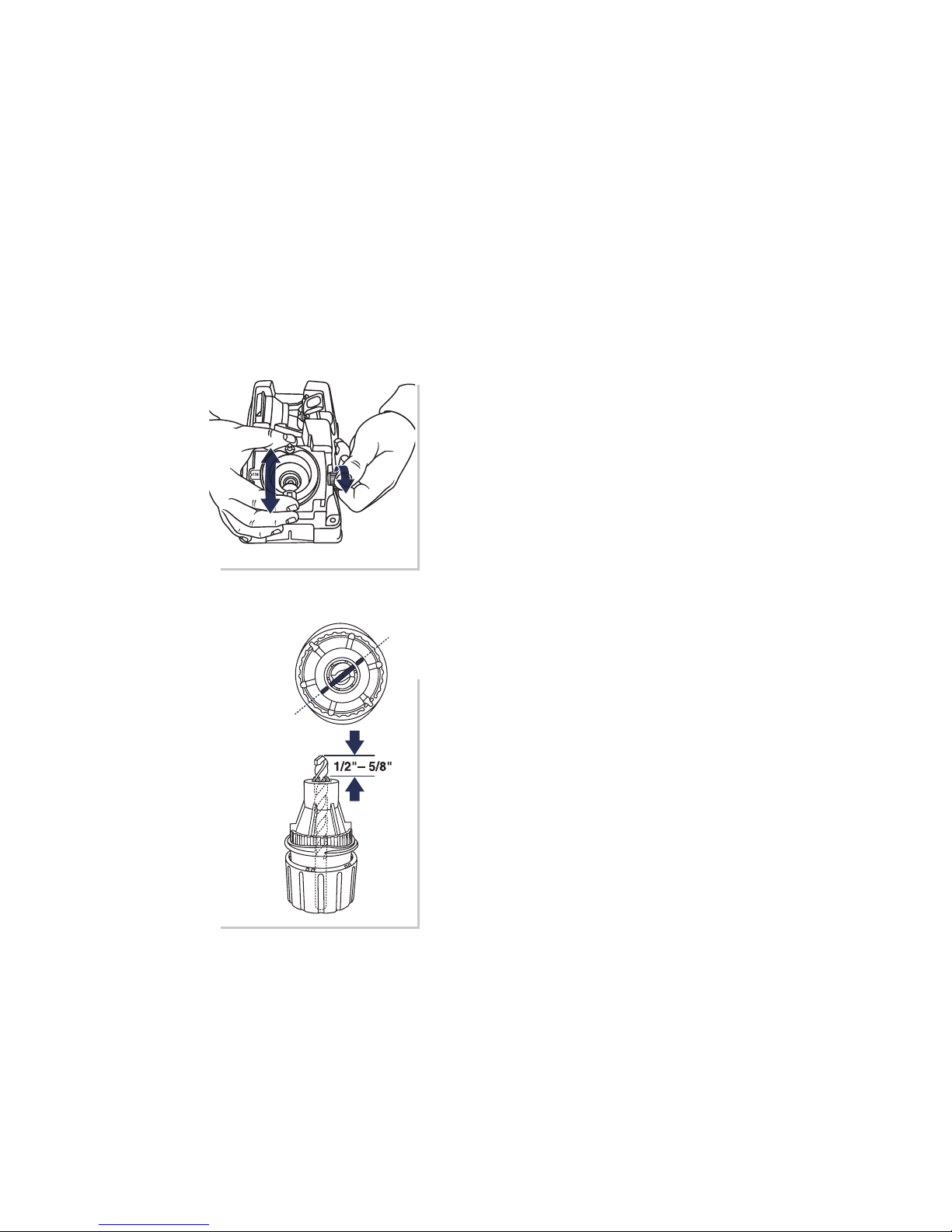
Masonry Drill Bits
To sharpen a masonry bit, you do NOT make rotations in the
Sharpening Port. Instead you sharpen by “plunging” - inserting
the chuck to sharpen one side, then removing it and repeating
on the other side.
Masonry
Sharpening
Marks
Align the bit with the Masonry
Sharpening Marks
Insert the bit into the Chuck and line
up the carbide insert on the tip of
the bit with the Masonry Sharpening
Marks on the end of the chuck. Leave
about 1/2”–5/8” of bit sticking out
past the nose of the Chuck. Tighten
the Chuck just to the point where the
bit slides in and out.
Set the point angle to 118°.
Page 26
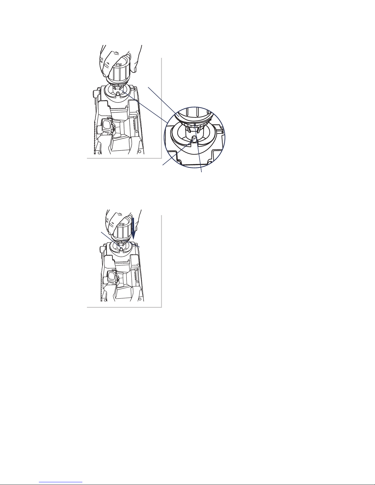
www.drilldoctor.com26
Cam Pin
Cam
Sharpening Guide
Cam
Pin
Cam
Set the Depth
Set the depth by lining up one of the
Sharpening Guides with the Cam Pin.
push the Chuck into the Sharpening
Port until it stops and tighten the
Chuck. Remove the Chuck to ensure
the insert is aligned
with the Masonry
Sharpening Marks
and tighten again.
Sharpen by “plunging”
Line up the Sharpening Guide (white
lines) on the Chuck with the Cam Pin
on the machine. Plunge the Chuck into
the Sharpening Port until it touches
the Sharpening Wheel. Remove the
Chuck, rotate one half-turn clockwise
and repeat. Inspect the bit and continue
until the cutting surfaces are sharp. If
the bit stops grinding before the edges
are sharp, reset the depth and sharpen
some more.
Using the Variable Alignment to Adjust the Chisel and
Relief Angles
Both models DD500X and DD750X enable you to adjust the
Chisel and Relief Angles of your drill bit. The Chisel and Relief
Angles have a direct effect on the performance of your drill. By
increasing the Relief Angle, you can increase the speed of the
drill in softer materials. To improve the quality of the hole, you
can adjust the drill to be less aggressive. A less-aggressive drill
has lower Chisel and Relief Angles. Your Drill Doctor enables
you to adjust both angles in one setting.
Page 27
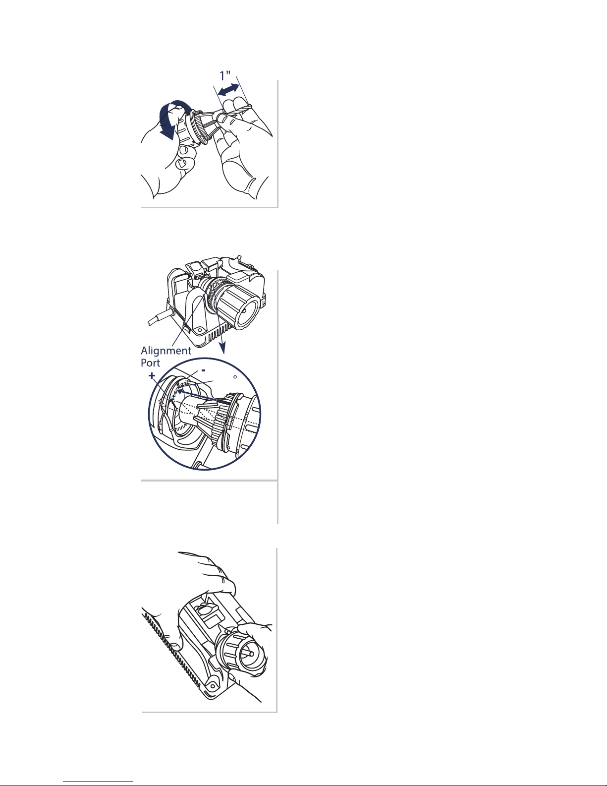
www.drilldoctor.com 27
Chuck bit as usual
To prepare your bit for this ne
adjustment, follow all the Steps for
chucking your bit given previously
in this User’s Guide.
Insert Chuck into Alignment
Port
To adjust the Chisel and Relief
Angles, simply align the bit
as usual with the following
adjustment:
To increase Relief—Insert the
Chuck in the Alignment Port closer
to the (+) position. This will make
a more aggressive drill point. Only
adjust 1-slot at a time.
To decrease Chisel and Relief—
Insert the Chuck in the Alignment
Port closer to the (-) position. This
will make a more precise hole. Take
care not to adjust Relief too far as
this will actually cause the drill to
lose all Relief and therefore not drill
a hole.
Each notch in the Alignment Port
is approximately a 10° change in
Chisel Angle.
Tighten Chuck, and sharpen as
usual
Experiment with a few dierent
settings to nd the one that best
suits your drill bit and application.
You may nd it helpful to mark this
setting for future use.
1.
2.
3.
118
Page 28
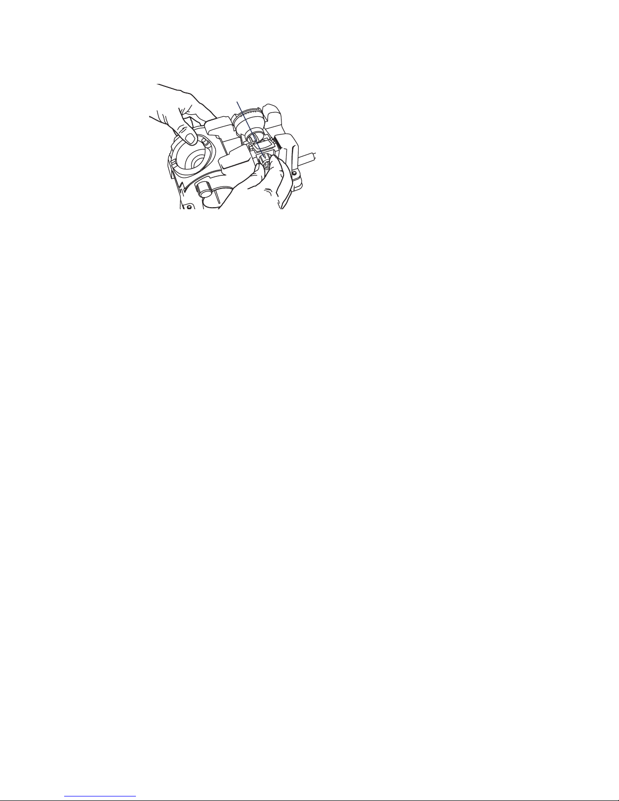
www.drilldoctor.com28
Variable Material
Take-Off Knob
The Model DD750X enables
you to remove more or less
material from the tip of
your bit when you sharpen.
If your bit is only slightly
dull and you simply wish
to “touch up” its point, turn
the Material Take-O (MTO)
Knob clockwise to reduce
the amount of material that is
removed from the drill bit. If your drill bit is quite dull or damaged,
turn the MTO Knob counter-clockwise to increase the amount
of material removed. The MTO adjusts from 0 to .040 of an inch.
Each mark on the MTO knob is equal to a .005” change in material
removed from the bit each time it is sharpened.
Using the Variable Material Take-O (MTO)
Questions and Answers
1. Question:
Why was my drill bit sharpened improperly?
Answer:
The most common cause of improper sharpening is incorrect
alignment.
Key causes are:
• Chuck not inserted into the Sharpening Port correctly.
Ensure the Alignment Guides (raised ns) are tted into the
correct alignment slot.
• Drill not aligned in the Chuck Jaws correctly. Ensure bit
clamp arms are holding in the narrowest part of the bit.
• The type of drill requires an angle adjustment to achieve
• the desired Chisel and Relief Angles. Try using the Variable
• Alignment to adjust the Chisel and Relief Angle.
• Chuck is dirty or the bit slipped out of alignment.
• See “Cleaning the Chuck.”
2. Question:
When I aligned the drill bit and sharpened it, why was no
material removed?
Page 29

www.drilldoctor.com 29
Answer:
Your sharpening tube may not be fully seated. Make sure the
small, black sharpening cup is sitting ush in the Sharpening
Port.
3. Question:
I sharpened the bit. Why will it not cut?
Answer:
This happens when the Heel on the bit is higher than the Cutting
Edge (negative relief ). You may have a specialty drill bit. Slow
and Fast Spiral, Helix, Turbo Flutes, and Raised Margin drill bits
are considered specialty bits. Follow the instructions in “Using
the Variable Alignment to Adjust the Chisel and Relief Angle.”
If you’re getting insufficient relief try aligning one notch towards
the (+) setting on the alignment port.
4. Question:
What can I do about flat spots between the Cutting Edge and
the Heel?
Answer:
The flat spots on a sharpened bit are the result of an incomplete
or paused half-turn of the Chuck in the Sharpening Port. To
correct, apply light, inward pressure and rotate the Chuck
smoothly while sharpening. Be sure to complete the half-turns.
5. Question:
Why is the drill point o center?
Answer:
• Make sure there are no particles between the Chuck Jaws
and the drill bit that could hold it o center. Check the drill
to ensure it is straight and free of burrs.
• Your drill bit may be bent.
Page 30

www.drilldoctor.com30
6. Question:
Why is the Chisel Edge on my drill bit at or rounded?
Answer:
• You may have aligned using the white Sharpening lines
instead of the raised Alignment Guides. Make sure to insert
either of the raised ns into the correct alignment slot.
• During the alignment process the Bit Clamp Arms were
gripping the high points of the drill bit. Realign the drill bit
making sure that the Bit Clamp Arms are holding the drill bit
in the narrowest section of the bit.
7. Question:
Why is my split point uneven?
Answer:
You may have used uneven pressure during the splitting process.
To correct an uneven point split, insert the Chuck into the
Splitting Port and split both sides again. Repeat until the split
sides are equal.
8. Question:
Why does the drill bit back up into the Chuck during the
sharpening procedure?
Answer:
• Your Chuck may be dirty. Follow the steps for cleaning the
chuck.
• Your bit may have been loose in the Chuck. Make sure to
tighten adequately before sharpening.
9. Question:
When splitting, why don’t I hear a grinding sound?
Answer:
The Chuck is not seated properly in the Splitting Port. The Chuck’s
Sharpening Guide must line up with the Splitting Guide on the
top of the Split Point Port. Firmly and slowly push the Chuck into
the hole until you hear grinding.
Page 31

www.drilldoctor.com 31
10. Question:
Can I change a 135° drill bit into a 118° drill bit?
Answer:
While you can change the degree angle of any drill bit, they
will perform best when sharpened at the same angle they were
manufactured at.
Drill Doctor® Maintenance
After sharpening 20 to 25 drill bits, the drill bit grinding dust will
accumulate in the grinding compartment. Grinding particles will
promote wear in the Sharpening Port and Chuck, so cleaning on a
consistent basis can add life to your machine.
Before any maintenance or cleaning is performed, be sure to
unplug your Drill Doctor.
Removing the Wheel Access Cover
With the Drill Doctor unplugged, slide the Wheel Access Cover
forward to remove. It will come completely o for easy access. To
close, insert the Cover back into the slots and snap back in place.
Cleaning Your Drill Doctor
®
With the Drill Doctor unplugged, shake accumulated drill
bit grinding dust from behind the Wheel Acess Cover into a
disposable container. Remove dust particles around the wheel
with a small, dry brush. Dispose of the container and drill bit dust
in a safe and environmentally approved manner. With a dry cloth
wipe the inside and outside of the Sharpening Port to remove any
grinding dust that may have accumulated. A standard 1” vacuum
hose works equally well.
Cleaning the Chuck
Brush out with a small, dry brush.
Determining if Replacing the Diamond Grinding Wheel
Is Required
You get double the life of the Diamond Sharpening Wheel by
reversing it before you replace it. The Sharpening Wheel supplied
with the Drill Doctor® is designed to give you long and trouble free
service, with an average of more than 200 sharpenings for 3/32”
to 1/2” drill bits.
Page 32

www.drilldoctor.com32
The Sharpening Wheel will need to be changed if:
• Your drill bit has a shiny, mirror nish.
• Your drill bits burn or turn blue on the tip.
Contact the store or dealer where you purchased the Drill
Doctor
®
, or contact Drill Doctor® directly, to purchase a
replacement Sharpening Wheel.
Page 33
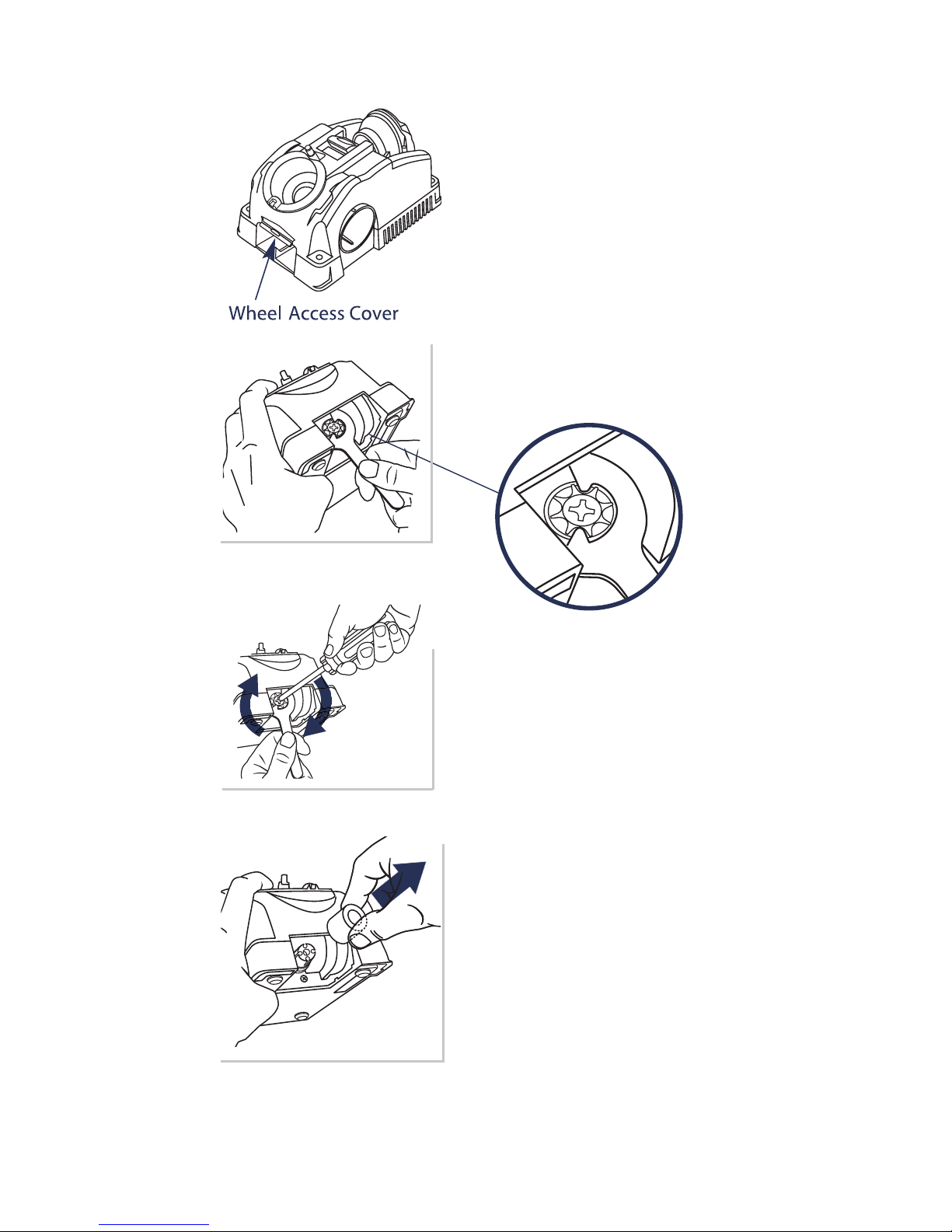
www.drilldoctor.com 33
1. Unplug your Drill Doctor, make
sure machine is cool, then remove
wheel access cover.
2. Use wrench supplied with your
Drill Doctor to hold sharpening
wheel in place.
3. With #3 Phillips head screwdriver,
remove one left-handed screw
(clockwise to loosen) and remove
the wheel retainer.
4. Remove worn wheel by twisting
slightly and lifting wheel o shaft.
Install new wheel and reinstall
wheel retainer and screw. Don’t
over-tighten mounting screw
(tighten to about 48 in/lbs).
Remove the wrench and replace
the Wheel Access Cover before
turning on the machine.
Reversing or Replacing Your Diamond
Sharpening Wheel
Page 34
www.drilldoctor.com34
Accessories
Order accessories by contacting us at the phone number listed on
the back cover, or at the retailer where you purchased your Drill
Doctor.
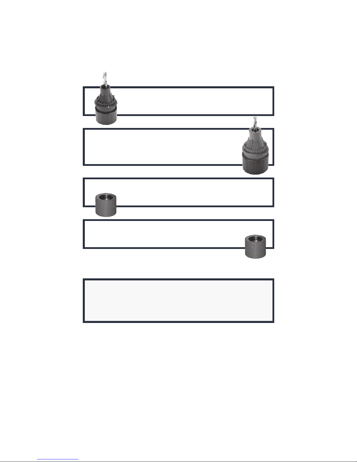
3/32” to 3/4” Large Bit Chuck
Part # DA70100PF
3/32” to 1/2” Left-handed Bit Chuck
(for 3/32”-1/2” reverse twist drill bits)
Part # DA02105PF
Standard Diamond Sharpening Wheel Kit (180 grit)
Part # DA31320GF
Coarse Diamond Sharpening Wheel Kit (100 grit)
Part # DA31325GF
⚠WARNING:
The use of any accessory other than one recommended
in this user’s manual may present a risk of personal injury.
Drill Doctor® Warranty
Darex, LLC warranties your Drill Doctor to be free of defects due
to workmanship or design for 3 years from the date of purchase.
For warranty service, contact your dealer with sales receipt.
Page 35

www.drilldoctor.com 35
Page 36

DAREX, LLC
P.O. BOX 730
210 E. Hersey St.
Ashland, OR 97520
USA
Phone
1-800-597-6170
Fax
541-552-1377
Web
www.DrillDoctor.com
Drill Doctor
®
is a registered trademark of DAREX, LLC
PP50122KF Rev 0 7/18
THE DRILL BIT SHARPENER
 Loading...