

Page 1
Patent
3,952,459
Brochure Includes:
• Set-up Instructions
• Operating Instructions
• Parts List
• Fundamentals of Drill Sharpening
Page 2
Accurately
Sharpens most drills bits.
Now, with this one low-cost, simple machine, several different types of drill
bits can be quickly sharpened: two, three and four fluted drill bits, Flat
Bottom and Core Drills. Precision work!
Quickly
With just a little experience, anyone can become an expert.
It takes only a few minutes to set up and have ready for operation this
Lisle 91000 Drill Grinder. A few minutes reading ALL OF THE OPERATING
INSTRUCTIONS will ensure the right start. A little practice and most every
machine shop can be doing all its own sharpening the first day. Comes
complete!
Economically
Without a major investment, every plant can own its own Drill Grinder.
The cost of commercial sharpening (to say nothing of the time it takes to get
the work done commercially) plus the rapid increases in the cost of new bits
makes owning and operating a Lisle 9100 Drill Grinder a practical,
money-making investment.
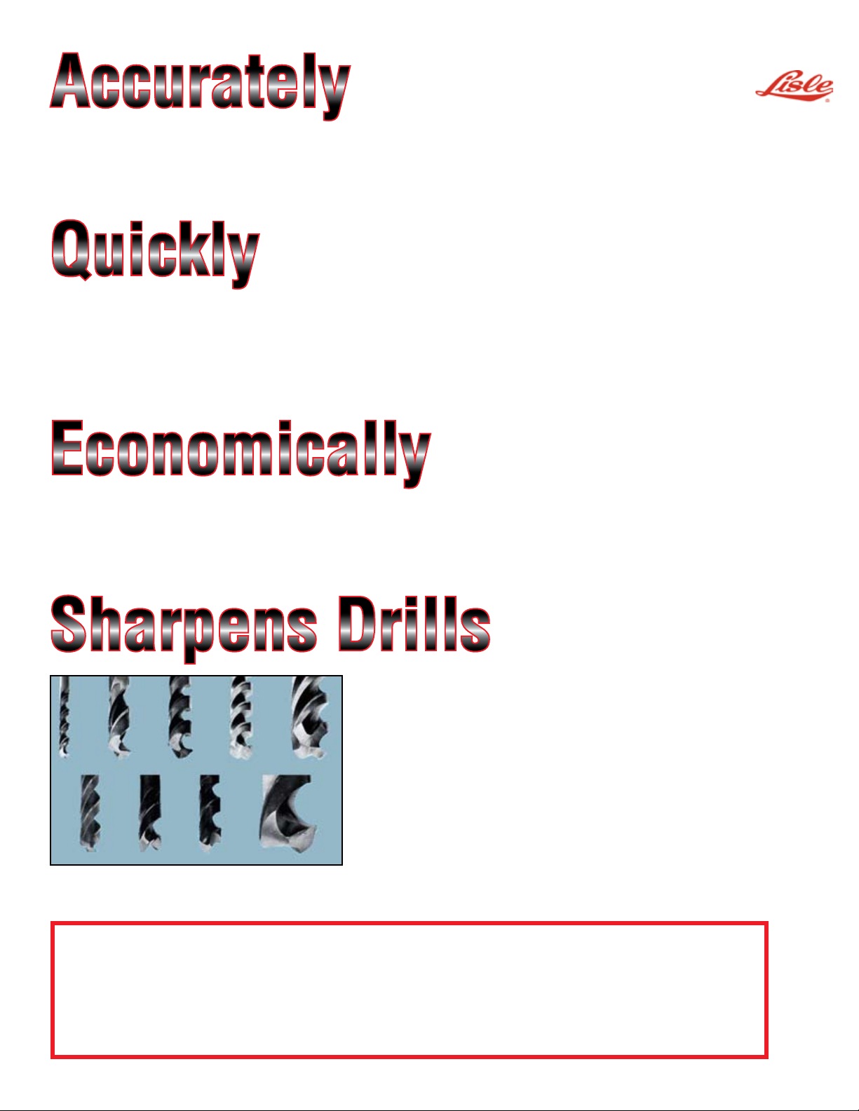
Sharpens Drills
From 1/8" up to 1 1/4" in size.
The Lisle 9100 can handle drill bits as small as 1/8" up to and
including 1 1/4". This machine will properly sharpen bits with
straight or tapered shanks. Correct tolerances for heel clearance,
1 2 3 4 5
6 7 8 9
The Lisle Drill Grinder 91000 is assembled at the factory to such an extent that it takes only minutes to set-up
and be ready to operate. HOWEVER, it will pay to read through the set-up and operating instructions on a step
by step basis prior to starting. This will help assure success on the first try and will also make the set-up easier
and avoid the necessity of re-doing any work.
EACH PHOTOGRAPH IN THIS BROCHURE IS NUMBERED FOR QUICK REFERENCE TO SPECIFIC
PROCEDURES, ASSEMBLIES, PARTS AND ADJUSTMENTS WHICH ARE MEANINGFUL TO BOTH SET-UP AND
OPERATION.
chisel or web angle, and cutting lip angle are locked into position
if properly set-up. Adjustments for various types and sizes of bits
are quickly and easily made. No guess work or estimates.
1. 1/8" Standard Drill, 2. 1/4" Low helix Drill, 3. Standard 1/2" Drill,
4. 1/4" High helix Drill, 5. 4 Fluted Core Drill, 6. 3 Fluted Core Drill,
7. Flat Bottom Drill, 8. Standard 1/4" Drill, 9. 1 1/4" Standard 2
Fluted Drill.
Page 3
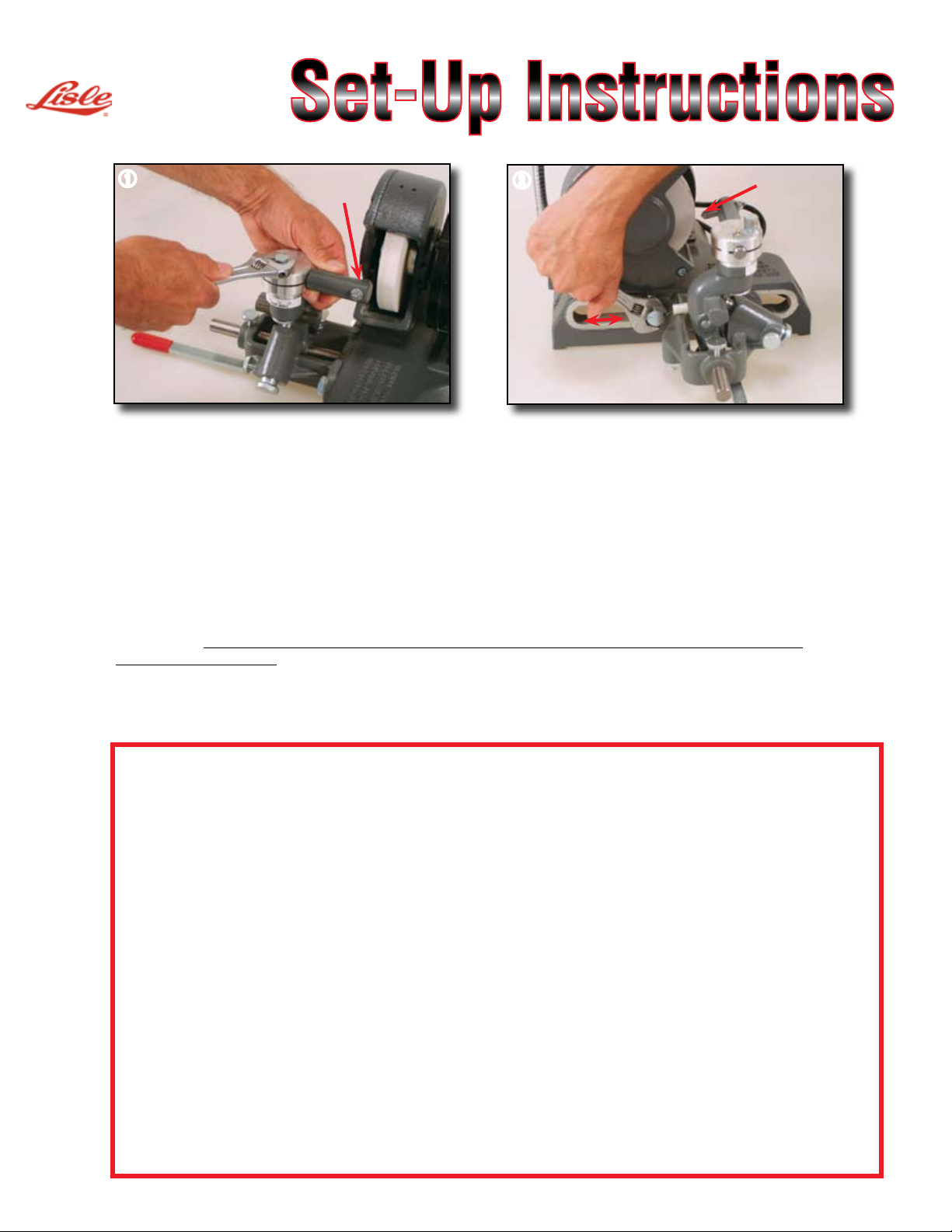
Set-Up Instructions
q
A
1. If possible, bolt Drill Grinder to left hand corner of work bench.
2. Install protective plastic shield with screws provided. Helps meet OSHA standards.
3. FOR FEED BRACKET ADJUSTMENT: (See photo 1) First, release the feed screw (A) until the rocker
arm is in the full relaxed position. Align the marks on the diamond dresser and split bushing before
tightening in place. Slide the feed bracket assembly (See photo 2) until the diamond is
approxmately 1/4" from the stone. Tighten feed bracket in place.
4. TO DRESS THE GRINDING WHEEL: Plug motor into a three wire ground outlet and turn motor on.
CAUTION! When dressing the stone or drill sharpening it is recommended that eye protection be
worn to prevent personal injury. Advance feed screw until the diamond just touches the grinding
wheel. Loosen the cross-feed lock screw (See photo 14) and move the cross-feed lever to work the
diamond back and forth across the grinding wheel.
NOTE: As the grinding wheel becomes unevenly worn from use, regular dressing will assure quality
sharpening. Also, regular adjustment of the feed bracket to the reduced size of grinding wheel is a
necessity. (See item 3)
Diamond
Dresser
w
1/4"
If the grinding wheel housing becomes loose, tighten the two (X) set screws. (See Photo 3)
AFTER MASTERING SET-UP FOR STANDARD TWO FLUTED DRILLS, APPLY THESE VARIATIONS FOR OTHER
TYPES DRILLS.
Sharpening Special Purpose Drills
(See Photo 13)
Flat Bottom (180 degree included Angle) -- First, split bushing should be set at 180 degrees (See
operating instructions “I”). Loosen the two bolts holding the feed bracket and move it as far forward as
possible. Position the drill in the drill holder as you would for grinding a standard drill point. Place the drill
holder in the split bushing and advance the feed screw. As the drill approaches the stone, move the crossfeed lock screw. Grind the first lip in the normal manner. Set the stop sleeve, back up the feed screw, rotate
the drill and grind the second lip.
Core Drill (3 Fluted) -- Position drill in holder with first lip parallel to the center line of the “V” of the drill
holder. Do not use set-up line on stop lip for this grind. Move stop lip to margin of drill and tighten. Proceed to
grind first lip as you would on a two fluted drill. Set the stop sleeve, back up the feed screw, rotate the drill
and grind the second lip. Continue until all cutting lips have been ground.
Core Drill (4 Fluted) -- Position drill in holder with the first lip parallel to the center line of the “V” (same as 3
fluted) (See photo 9). Do not use set-up line on stop lip for this grind. Move stop lip to margin of drill and tighten.
NOTE: The grinding procedure on this drill is different because of the closeness of the cutting lips. Place drill
holder in split-bushing and position the holder so that the axis of the drill is at an angle of about 10 degrees
below the horizontal (about 2" drop at the end of the drill holder shaft) before tightening in place (See photo
13). Advance the feed screw until first lip just touches the grinding stone. Then with quick motions, advance
the feed screw slightly and back it off to avoid burning. This can best be done by rocking the feed screw
back and forth. Continue until the first lip is ground, then quickly tighten the stop sleeve and back off the
feed screw. Examine the clearance angle on the lip which was just sharpened. If the clearance angle looks
acceptable, then proceed to grind the remaining lips in the same manner. If the clearance angle is not
acceptable, then the angle of the drill with the horizontal will have to be changed. Decreasing the angle will
decrease the clearance and increasing the angle will increase the clearance.
Page 4

Operating Instructions
e
r
Loosen to
Set
Split Bushing
B
C
Set Screws X
Angle
Setting Clearance Angle
D
I. To obtain desired point angle:
The split bushing on the rocker arm is
calibrated in degrees and can be
adjusted to sharpen drills at various
included point angles. Loosen bolt
under rocker arm which holds the split
bushing in place and set at desired
angle (normally 118 degrees). Tighten
bolt (See photo 3).
II. To set clearance angle: Loosen bolt
holding the pivot shaft (B). Then
loosen the screw holding the lip
clearance adjuster (C) and align the
mark with the desired clearance angle
(D) (See photo 4). The center mark
gives 12 degrees clearance and is
best for average drilling. The top
position gives 18 degrees and the
bottom position gives 6 degrees
clearance. Now, tighten the screw
(But not the bolt).
t
Setting for
Drill Size
III. To set for drill size: Align the mark on
the pivot shaft assembly (See photo
5) with the mark corresponding to the
diameter of the drill to be sharpened.
Now, tighten the assembly in place.
Page 5

Operating Instructions
IV. To clamp drill in drill holder: First,
place magnet extension gauge on
stop lip as shown (See photo 6). The
magnet gauge is made so that one
side of the magnet extends 3/32 of an
inch and the other side 1/8 of an inch.
Use the shorter 3/32 inch side for drills
up to 3/8 inch diameter and the longer
1/8 inch side for drills larger than 3/8
inch diameter. Place drill in clamp and
move the drill toward the magnet
gauge until the edge of the cutting
lip just touches the bottom of the
gauge. Tighten drill clamp.
Contact Point
y
Magnet Gauge
u i
Drill Clamp
V. To adjust end-stop and V-block: Slide
end-stop along the square shaft until it
rests firmly against the drill. Then move
the V-block so that it helps support the
shank of the drill (See photo 7). The
small rod on the end-stop is used when
sharpening short drills by reversing
end-stop on square shaft (See photo 8).
VI. To set drill rotation: (See photo 9)
Loosen the top screw (in the curved slot)
on the stop lip and turn clockwise as far
as it will pivot. Then loosen the drill clamp
just enough so that the drill may be
rotated. Turn the drill until the first cutting
lip is parallel with the scribe line (See
dotted line) on the stop lip. The cutting
lip and scribe line will not line up, but will
be parallel. Tighten drill clamp. Second
screw is for height adjustment depending
on size of drill.
‘V’ Block
End Stop
o
Setting Drill Rotation
Stop Lip
Drill
Clamp
Small Rod for short
or small Drill bits
Loosen Top Screw &
rotate stop lip cloclwise
Groove
Page 6

Operating Instructions
1) 1!
Setting Stop Lip
Loosen for
up & down
movement
1@
1#
15˚
4"
VII. To set stop lip: Move the stop lip
counter clockwise so that the edge just
catches the margin of the drill flute.
Note that the stop lip can move up and
down as well as in and out. Now,
tighten stop lip in place (See photo
10). If you have done everything
correctly, the cutting lip should be at a
15˚ angle from the pivot shaft as shown
in picture 11.
VIII. To mount drill holder in split
bushing: Slide drill holder assembly
into split bushing (just as you did the
diamond dresser) (See photo 1) until
groove in pivot shaft engages the
spring loaded plunger. Tighten the
bushing just enough so that the drill
holder assembly can freely pivot in the
bushing.
IX. To sharpen the first lip of the drill:
Loosen stop sleeve lock screw before
sharpening first lip so that the stop
sleeve can slide back against the feed
screw (See photo 14). Grasp the drill
holder with your right hand and move
the drill up and down (approximately
two times per second) as you advance
the feed screw with your left hand
(See photo 12). Slowly advance the
feed screw until the first lip is
sharpened.
X. To set the stop sleeve: Tighten stop
sleeve lock screw after sharpening the
first lip. By doing this, you will be
able to grind the second drill lip
exactly the same as the first lip. Turn
the feed screw again to be sure that
there is no slack between the feed
screw and the stop sleeve. Move the
drill holder up and down a few more
times in case any movement has taken
place.
XI. Preparing for second or additional
lips: Back off the feed screw a few
turns and shut off the motor. Loosen
the drill clamp slightly and rotate the
drill until the second lip is tight against
the stop lip. Keep the drill tight against
the stop lip and end stop as you
retighten the drill clamp.
XII. To sharpen second lip: Advance
feed screw following same procedure
as in “Paragraph IX: To sharpen the
first lip of the drill”; until stopped by the
pre-set stop sleeve. Proceed with all
lips in the same manner. Always turn
off motor to remove drill or drill
holder assembly.
Page 7

1$
Page 8

Fundamentals of Drill
Sharpening
Before sharpening a drill bit, it is important that one be familiar with basic
drill terminology and the fundamentals of drill sharpening. Figure 1 below shows
some of the basic terminology related to a standard twist drill.
A properly sharpened drill is one where the cutting edges (lips) are sharp,
equal in length and have adequate clearance behind them. This clearance is
properly referred to as lip clearance.
In Figure 2, the two cutting lips are shown as A1 and A2. The
surfaces behind the cutting lips are shown as B1 and B2.
If the surfaces B1 and B2 are higher than the cutting lips, then
the cutting lips will not contact the work and the drill will not cut.
Figure 3 shows examples of drills with correct and incorrect
lip clearance.
LISLE CORPORATION, CLARINDA, IOWA 51632 712/542-5101 FAX : 712/542-6591 www.lislecorp.com
© 2005 Lisle Corporation Form DG-05 Printed in U.S.A.
900290.86
 Loading...