

Page 1
follow us
facebook.com/driftinnovation
vimeo.com/driftinnovation
instagram.com/drift_innovation
twitter.com/driftinnovation
DRIFTINNOVATION.COM
quick guide
Page 2

Thank you for purchasing the Drift Stealth 2
CUSTOMER SUPPORT
Check our ocial website for firmware updates, customer
support, news about our products and videos from our users.
If you have any suggestions, comments or concerns, please
contact our customer support team at:
WARRANTY
Warranty does not apply if the product is damaged due
to physical abuse, mishandling, accident, fire, frostbite,
water damage, negligence or failure to follow the supplied
operating instructions.
contents
about your camera | initia l setup 3—4
package contents | getting started 5—6
mode selectio n & settin gs 7—8
fea tures 9—10
mounting the cam era | accessory guide 11—12
wifi | connecting t he came ra 13—14
specifications 15—16
disclosures 17—18
Page 3
about your camera initial setup
C
A
B
F
G
D
E
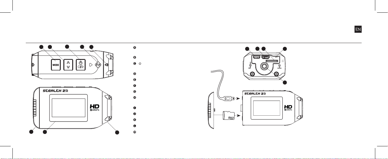
MODE/ Tag / Simultaneous
Photo Button
CYCLE OPTION Button
ACTION Button
(On/O/Rec/Stop)
Status LED
Lens “Up” Indicator
Rear Hatch
1.3” Backlit LCD S creen
300° Rotating/Replaceable
Lens
HDMI Port (Micro-D)
USB Port (M icro-B)
Micro SD Ca rd Slot
Reset Button
Rear Hatch Screw Point
H
I
K
J
L
1. Unscrew and remo ve
the rear h atch
2. Insert a C lass 6 or
higher Micro SD/HC/
card (up to 32GB)
M
Format before first
usage!
3. Connect the camera
via micro USB cable
to a powere d USB
port an d charg e the
batter y for 4 hou rs
before fi rst use
4. Repl ace the re ar
hatch and screw shu t
to secure
43
Page 4
package contents
getting started
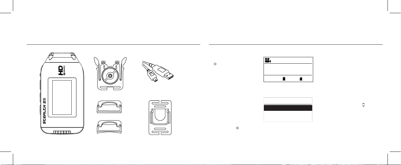
Universal Clip
Mount Kit
5
USB Cable (Micro-B)
Goggle Mount
POWER ON AND OFF
1. Press and hold the
ACTION button to
power on
2. T he scree n will power
on, show the welcom e
display.
3. T he camera is now ready
to record video, or ta ke
still ph otos
4. The current camera mode
is indic ated by the icon in
the top lef t of the display
and by the LED indicator
(for details, s ee p 7-8 )
5. To power o, press
and hold the ACTION
button fo r 3 second s
*Note: The camera will power on in the same mode it powered o in.
25 FPS
12:05:59
EXP -2
VIDEO INTERFACE
S
Exposure
Self Timer
Wi-Fi
SETTINGS INTERFACE
1080p
90%
GNITTE
MODE NAVIGATION
To change the current
camera recording mode
press the [MODE] button,
changing between;
Video, Photo, Tim elaps e,
87%
Photoburst and the camera
general setting modes.
MODE SETTINGS
To change the settings
of the current came ra
mode pre ss the CYCLE [ ]
0.0
button. This will change
the settings bet ween a
X
selection of presets.
X
6
Page 5
settingsmode selection
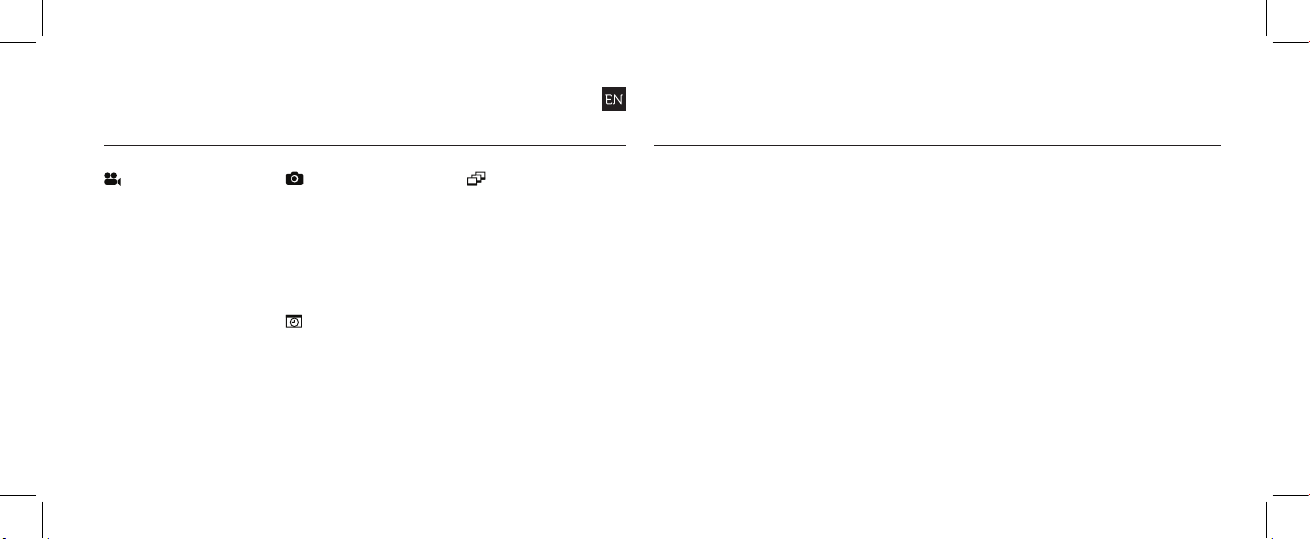
VIDEO MODE
(Green L ED) The ca mera
will record video w hen
ACTIO N is press ed on the
camera or remote. The
LED will flash red while
recording. Press ACTION on
the camera, or S TOP on the
remote, to end recording.
NTSC vs PAL
The cam era records in
both NTSC and PAL video
standards (changeable from
the settings menu) NTSC
delivers frame rate intervals
of 30 (30, 60, 120) FPS
whereas PAL uses frame
rate inter vals of 25 (25, 50,
100) FPS.
PHOTO MODE
(Yellow LED) The cam era
will capture still images
when ACTION is pressed
on the camera or remote.
The LED wi ll blink red ever y
time a photo is taken (th is
applies for Timelapse and
Photoburst modes also).
TIMELAPSE MODE
(Purple LED) The camera
will capture a seri es of still
images at a specifi ed rate
when ACTION is pressed
on the camera or remote.
To stop recordin g, press
ACTIO N on the camera or
STOP on th e remote.
PHOTOBURST MODE
(Cyan LED) The camera
will capture a burst of still
images for an allot ted
duratio n, when ACTION
on th e camera or rem ote is
presse d (for best results , use
a Class 6 or higher m icro
SD card).
CAMERA SETTINGS
•EXP OSURE -2.0 / -1.0 / 0 / +1.0 / +2.0
•SELF-TIMER OFF / 3S / 5S / 10S
•WI-FI OFF / ON
•VIDEO TAGGING ON / OFF
•TAGG ING INTE RVAL 10S / 30S / 1MIN / 2 MIN / 5MIN / 10MIN
•CAR DVR M ODE ON / M / OFF
•CA R DVR IN TERVAL 1MIN / 3MIN / 5 MIN / 10MIN / 15MIN
•VIDEO STANDA RD NTSC (30) / PAL ( 25)
•MIC SENS ITIVITY OFF / LOW / MED / HIGH
•SPEAKER VO LUME OFF / LOW / MED / HIGH
•RC 1-1 ON / OFF
•RC 1-ALL ON / OFF
•RC LED ON / OFF
•CAME RA LED ON / OFF
•CAME RA OFF OFF / 2MIN / 5MI N
•LCD BACKLIG HT ON / OFF
•LCD BACKLIG HT TIMER OFF / 5S / 10S / 20S / 1M IN
7 8
•DATE YEAR / MON TH / DAY
•DATE / TIME S TAMP ON / OFF
•LANG UAGE [List of La nguages]
•RESET S ETTINGS YES / NO
•FORMAT MEM ORY CARD YES / N O
• FIRMWARE VERSION CURRENT VERSION
*Note: In set tings mo de, press ing the CYCLE b utton
once will m ove the sele ction dow n one setti ng.
Holding t he CYCLE but ton will move t he selec tion
back up the l ist to facilitate na vigation.
Page 6
features
PHOTO MODE
VIDEO MODE
PHOTO MODE
VIDEO MODE
MODE INDICATOR
The Drift Stealth 2 features
a multi-coloured status
indicator light s ystem. A
front facing LED combined
with a backlit LCD Disp lay
light up depending on the
current camera mode.
Either can be disa bled in the
general settings.
VIDEO - green
PHOTO - yellow
TIMEL APSE - purple
PHOTOBURST - cyan
*The mode indi cator is
compati ble with th e Drift
Two-Way remote con trol
VIDEO TAGGING
When activated, this feature
allows th e camer a to
continuously record video,
but only s aving on ‘tagging’
important footage.
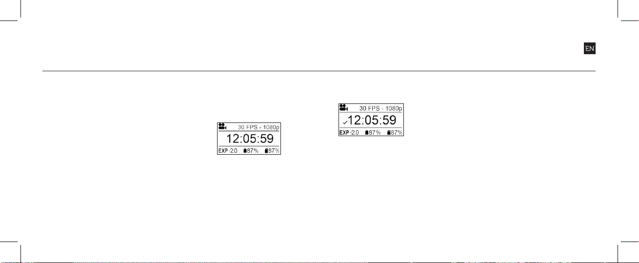
At the Standby screen, ‘T ’
indicates Vide o Tagging
is activ ated, and the set
Video Tagging Inter val is
displayed. (see Standby
Screen-Shot below)
T
10s
Pressing ACTION will be gin
the loop recordin g, but
without saving any footage.
The LED wi ll be blinking
green. (see Recording
Screen-Shot below)
T
x
While recording video,
pressing the MOD E button
will tag and save pa st,
present and future video
interv als. T he on scre en
indicator will turn to a
check mark and the L ED
indicator will bl ink red.
(see Tagging Screen-Shot
below)
T
For example, with a v ideo
tagging inter val of 30s
selected, on pressing MENU
while recording, the camera
will save t he previous 30s,
the current 30s and a n
additional 30s—a total of
1m30s of ‘ tagge d’ footage.
The Vide o Tagging fe ature
require s a class 10 micro SD
card with 4 GB of free space to
function correctly.
SIMULTANEOUS PHOTO
While recording video,
pressing the MOD E button
will simultane ously take a
2MP still photo.
When usi ng the two-way
remote control, pre ss the
ACTIO N button fo r the
same res ult.
This featu re is not availabl e when
Video Taggi ng (left) is enabled.
*see full manual for full detailed guide on how to use various features
CAR DVR MO DE
This hands o mode setting
is ideal for insurance and
security purposes. In this
mode the camera records
footage in a continuous
loop st yle (DVR Intervals)
recording loop af ter loop
until it fills the Mi cro SD
Card. Once full, the olde st
loops wi ll be deleted as the
newest ones are saved. DVR
loop interval s can be 1m in,
3min, 5min, 10min or 15min
intervals.
109
Page 7
mounting the camera
accessory guide
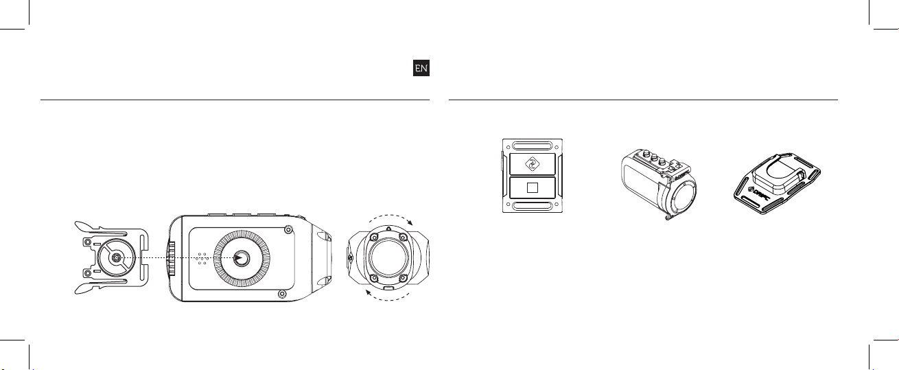
1. Attach the Universal Clip
to the camera in any 360°
orientation as needed—
first position the clip in
the desired orientation,
then secure by rotating
the screw base by hand
2. Slide the Universal Clip
into your chosen mount,
ensuring that it ‘clicks’
into place
*Double check it has been
fully inserted by pushing
out the clips
3. Align your shot. Rotate
the lens by hand until
the screen is orientated
correctly. Use the
lens marker as an ‘up’
reference.
TWOWAY REMOTE CONTROL
Get connected with the Drift
Two-Way remote control.
Start/stop recording, change
mode and ensure recording
with Drift LED mode
indicator integration.
*Note: For full accessory list visit driftinnovation.com
11 12
STEA LTH 2
WATERPROOF CASE
Become immersed with the
Stealth II Waterproof Case.
The dual locking system
creates an air tight seal and the
replaceable front lens keeps
the footage crystal clear.
DRIFT
VENTED HELMET MOUNT
Attach your Drift camera to
any vented bike, ski, or similar
sports helmet with the new
Drift Helmet Vented Mount.
Page 8
wifi firmware
connecting the camera
TURNING ON AND OFF
In the Camera Set tings
menu, highlight the ‘W iFi’
option and press AC TION ,
and sele ct P and pres s
ACTION.
The net work name (SSID)
of your camera wil l be
‘Stealth 2 XXX XX ’ where
the digits corres pond to
your cam era’s uni que serial
number.
DOWNLOAD T HE DRIFT APP
Shot setu p, record,
capture & p layback
on your device.
UPDATING THE FIRMWARE
Downlo ad the latest firmware
from the Drift website (left)
and copy th e STEALTH 2.bin
file to a formatted micro
SD card.
Inser t the micro S D card
into the camera and power
on. The camera screen will
display ‘Firmware Updating’
as the upd ate is installed.
Once complete, the camera
will power down. To check
the firmware has updated
correctly, power the camera
on and, from the Mai n menu,
open the Camera Settings
menu and select ‘Version’ to
view the cu rrent firmware.
CONNECTING TO A PC
1. Conn ect the c amera
using the USB cable
(provided); the camera
screen will show a US B
icon
2. The camer a’s folder may
open automatically; if
not, open My Computer
3. The camer a should
be recognised as a
removable disk; doubleclick to open
4. Open the DCIM fo lder to
access your files
! While cha rging only (not thr ough a computer), press ACTI ON to power o n the unit
CONNECTING TO A MAC
1. Conn ect the c amera
using the USB cable
(provided); the camera
screen will show a US B
icon
2. The camer a’s folder may
open automatically; if
not, open Finder
3. The camer a should be
recogni sed as a ex ternal
device; double-click to
open
4. Open the DCIM fo lder to
access your files
CONNECTING TO A T V
1. While the camera is
powered o, connect
the camera using a micro
HDMI (Type D) to full
HDMI cable, available
from Drift retai lers.
2. Power on the ca mera
3. The camer a’s displ ay will
now show on the TV
and play back of vi deo
or photos will show on
screen; video sound
will come out of the T V
speakers
1413
Page 9

specifications
Video resoluti on: 1080p, 720p and W VGA (16:9); 96 0p (4:3)
File form at: .MP4 (H .264 co dec)
Sensor type: CMOS
Frame rate:-
1080p: 25 / 30 fps
960p: 25 / 30 fps
720p: 25 / 30 / 50 / 60 fps
WVGA : 25 / 30 / 100 / 120 fps
Field of view (diagonal): 135°
Lens focal range: 0.5m to infin ity
Lens rotation: 300°
Photo mod e: 12 / 5 / 3 megapixels
Exposure: Auto / Manual (advanced users)
LCD Screen: 1.3” mono graphic backl it LCD
Water Resis tance
Microphone: Built-in, noise reducing microphone
Built-in memory: 256MB (not user accessible)
Memor y capacity: Micro SD memory cards up to 32GB
Output s: Micro HDMI conn ector - t ype D (cable not included)
Connec tivit y: USB Plug and Play, micro-B USB connector
Compati bilit y: Windows XP and up / Mac OS 10.2 and up
Remote range: 10m (32.81ft)
Radio frequency: 2.4GHz
Dimensions: 80.0 (L) × 42 .6 (W) × 27.4 (D) mm
Weight: 94g
Power: 1500mAh internal lith ium-ion b attery (DC 3.7 V)
1615
Page 10

FCC Caution.
§ 15.19 Labelling requirements.
This device complies with part 15 of the FCC Rules. Operation is subject to the following
two conditions: (1) This device may not cause harmful interference, and (2) this device must
accept any interference received, including interference that may cause undesired operation.
§ 15.21 Information to user.
Any Changes or modifications not expressly approved by the party responsible for
compliance could void the user's authority to operate the equipment.
§ 15.105 Information to the user.
Note: This equipment has been tested and found to comply with the limits for a Class B
digital device, pursuant to part 15 of the FCC Rules. These limits are designed to provide
reasonable protection against harmful interference in a residential installation. This
equipment generates uses and can radiate radio frequency energy and, if not installed and
used in accordance with the instructions, may cause harmful interference to radio
communications. However, there is no guarantee that interference will not occur in a
particular installation. If this equipment does cause harmful interference to radio or television
reception, which can be determined by turning the equipment off and on, the user is
encouraged to try to correct the interference by one or more of the following measures:
-Reorient or relocate the receiving antenna.
-Increase the separation between the equipment and receiver.
-Connect the equipment into an outlet on a circuit different from that to which the receiver is
connected.
-Consult the dealer or an experienced radio/TV technician for help.
Specific Absorption Rate (SAR) information:
This STEALTH 2 meets the government's requirements for exposure to radio waves. The
guidelines are based on standards that were developed by independent scientific
organizations through periodic and thorough evaluation of scientific studies. The standards
include a substantial safety margin designed to assure the safety of all persons regardless of
age or health.
FCC RF Exposure Information and Statement The SAR limit of USA (FCC) is 1.6 W/kg
averaged over one gram of tissue. Device types: FD9963 (FCC ID: P2F-FD9963) has also
been tested against this SAR limit. The highest SAR value reported under this standard
during product certification when properly worn on the body is 0.342W/kg. This device was
tested for typical body-worn operations with the back of the handset kept 0cm from the body.
To maintain compliance with FCC RF exposure requirements, use accessories that maintain a
0cm separation distance between the user's body and the back of the handset. The use of belt
clips, holsters and similar accessories should not contain metallic components in its assembly.
The use of accessories that do not satisfy these requirements may not comply with FCC RF
exposure requirements, and should be avoided.
Body-worn Operation
This device was tested for typical body-worn operations. To comply with RF exposure
requirements, a minimum separation distance of 0cm must be maintained between the user’s
body and the handset, including the antenna. Third-party belt-clips, holsters, and similar
accessories used by this device should not contain any metallic components. Body-worn
accessories that do not meet these requirements may not comply with RF exposure
requirements and should be avoided. Use only the supplied or an approved antenna.
 Loading...