

DRIESCHER-WEGBERG MINEX-C ABS zero Operation And Assembly Instructions
Montage- und Betriebsanleitung
Operation and Assembly Instructions
© DRIESCHER • WEGBERG
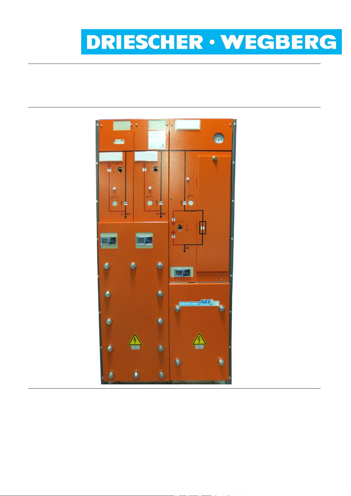
Mittelspannungs-Lastschaltanlage
Typ MINEX
SF
-isoliert
6
Bemessungsspannung bis 24 kV
Bemessungsstrom 630 A
®
-C ABS zero
Medium Voltage Switchgear
®
Type MINEX
SF
-insulated
6
Rated voltage up to 24 kV
Rated current 630 A
-C ABS zero
04/2018

DRIESCHER WEGBERG
Alle Rechte vorbehalten / All rights reserved
DRIESCHER WEGBERG 2018
2 MINEX
®
-C ABS zero (DE-EN)

DRIESCHER WEGBERG
INHALT CONTENTS
Inhalt 3 Contents 3
Sicherheitsvorschriften 5 Safety Regulations 5
Allgemeine Information 6 General Information 6
Bestimmungsgemäße Verwendung 6 Intended Use 6
Qualifiziertes Personal 6 Qualified Personnel 6
Normen und Vorschriften 7 Standards and Specifications 7
Betriebsbedingungen 8 Operating Conditions 8
Haftungsbeschränkungen 8 Liability Limitations 8
Beschreibung 9 Description 9
Allgemeines 10 General 10
Anti-Berst-System (ABS) 11 Anti-Burst-System (ABS) 11
Kapazitive Schnittstelle 15 Capacitive Interface 15
Übersicht 18 Overview 18
Technische Daten 19 Technical Data 19
Bemessungsgrößen 19 Rated Values 19
HH-Sicherungseinsätze 22 HV HRC Fuses 22
Abmessungen und Gewichte 23 Dimensions and Weights 23
Kabelendverschlusstabellen 26 Tables for the Cable Terminations 26
Montage 29 Assembly 29
Sicherheitshinweise für Transport, Montage,
Betrieb und Wartung 29
Abladen und Transportieren 29 Discharge and Transport 29
Aufstellen der Schaltanlage 31 Positioning of the Switchgear 31
Schaltanlage erden 33 Earthing the Switchgear 33
Anschluss 34 Connection 34
Öffnen der Kabelraumblende 34
Entfernen des Blenden-Halterahmens 35
Entfernen der Kabelhalteeisen 37 Removal of the Cable Holding Iron 37
Vorbereiten der Gummi Pressdichtung 38 Prepare of Rubber Gasket Seal 38
Kabel einführen und montieren 38 Insert Cable and assemble 38
Kabel druckfest abdichten 39 Seal Cables pressure-tight 39
Montage der Kabelhalteeisen 39 Installation of Cable Holding Iron 39
Hilfsstromkreis anschließen 41 Connection of Auxiliary Circuits 41
Betrieb 42 Operation 42
Inbetriebnahme 42 Setting to Work 42
Bedienung 43 Operation 43
Schalten des Lasttrennschalters 44 Switching Switch-Disconnector 44
Schalten des Erdungsschalters 46 Switching Earthing Switch 46
Austausch der HH-Sicherungseinsätze 47 Replacement of HV HRC Fuses 47
Kabelprüfung und Kabelfehlerortung 49 Cable Testing and Cable Fault Location 49
Optionale Ausstattung 50 Optional Equipment 50
Motorantrieb (Option) 50 Motor Mechanism (Option) 50
Notentriegelung 51 Emergency Unlocking 51
Magnetauslöser (Option) 52 Trip Coil (Option) 52
Kurzschlussanzeiger (Option) 53 Short Circuit Indicator (Option) 53
Erdschlussanzeiger (Option) 53 Earth Fault Indicator (Option) 53
Safety Instructions for Transport, Assembly,
Operation and Maintenance 29
Opening of Cable Compartment Cover 34
Removal of retaining frame 35
MINEX
®
-C ABS zero (DE-EN) 3

DRIESCHER WEGBERG
Instandhaltung 54 Servicing 54
Austausch von Bauteilen / Entsorgung 55 Exchange of Components / Waste Disposal 55
Prüfen der Schaltanlage 56 Testing the Switchgear 56
Prüfen des Isoliergasdruckes 57 Testing the Insulating Gas Pressure 57
Fehlerbehebung 59 Trouble-Shooting 59
Anhang A 60 Appendix A 60
Montageanleitung der Gummipressdichtung
der Firma UGA
Anhang B
Deaktivierung der Sicherungsauslösung 62 Fuse Trip Deactivation 62
Aktivierung der Sicherungsauslösung 62 Fuse Trip Activation 62
Anhang C 63 Appendix C 63
Demontage / Montage der Frontblende 63 Disassembly / Assembly of front cover 63
Isoliergas Schwefelhexafluorid SF6 64 Insulating Gas Sulphur Hexafluoride SF6 64
60
62
Installation Manual of Rubber Gasket Seal issued by Company UGA
Appendix B
60
62
4 MINEX
®
-C ABS zero (DE-EN)
DRIESCHER WEGBERG
Sicherheitsvorschriften
Die in der Betriebsanleitung enthaltenen Hinweise zu
- Transport
- Montage
- Inbetriebnahme
- Bedienung
- Wartung
der Mittelspannungs-Schaltanlage müssen unbedingt
beachtet werden.
Wichtige sicherheitstechnische Hinweise sind durch
folgende Symbole gekennzeichnet. Befolgen Sie
diese Hinweise, um Unfälle und Beschädigungen der
Mittelspannungs-Schaltanlage zu vermeiden.
Warnung vor einer Gefahrenstelle!
Warnung vor elektrischer Spannung!
Besondere Hinweise!
Safety Regulations
It is imperative that the notes in these Operating Instructions regarding
- transport
- assembly
- setting to work
- operation
- maintenance jobs
of the medium voltage switchgear are adhered to.
Important instructions such as safety notes are identified by means of the following symbols. Follow these
notes to avoid accidents and damage involving the
medium voltage switchgear.
Warning of a danger area!
Warning of electrical voltage!
Special hints!
Diese Symbole finden Sie bei allen Hinweisen in dieser Betriebsanleitung, bei denen Verletzungs- oder
Lebensgefahr besteht.
Beachten Sie diese Hinweise und geben Sie diese an
anderes qualifiziertes Personal weiter. Neben diesen
Hinweisen sind
- Sicherheitsvorschriften,
- Unfallverhütungsvorschriften,
- Richtlinien und anerkannte Regeln der Technik,
sowie sämtliche Instruktionen dieser Montage- und
Betriebsanleitung zu beachten!
You will find these symbols with all hints given in this
manual, where risk of injury or danger of live exists.
Comply with these notes and pass them on to other
qualified electrical technicians. Aside from these
notes, comply with
- Safety specifications
- Accident prevention regulations
- Guidelines and recognized rules of technology
as well as all instructions and notes in these Operation
and Assembly Instructions!
MINEX
®
-C ABS zero (DE-EN) 5

DRIESCHER WEGBERG
Allgemeine Information
Bestimmungsgemäße Verwendung
Die DRIESCHER SF
typgeprüfte Mittelspannungs-Schaltanlage für Innenraumanwendung mit Schwefelhexafluorid (SF
Isolier- und Löschgas und entspricht den zum Zeitpunkt der Auslieferung gültigen Gesetzen, Vorschriften und Normen. Die Mittelspannungs-Schaltanlage
vom Typ MINEX-C ABS zero ist ausschließlich zum
Schalten und Verteilen elektrischer Energie mit Strömen bis 630 A bei Spannungen bis 24 kV, 50/60 Hz
bestimmt.
Der einwandfreie und sichere Betrieb der Schaltanlage setzt voraus:
Sachgemäßer Transport und fachgerechte Lage-
rung
Fachgerechte Montage und Inbetriebnahme
Sorgfältige Bedienung und Instandhaltung durch
qualifiziertes Personal
Die Beachtung dieser Anleitung
Die Einhaltung der am Aufstellungsort geltenden
Aufstellungs-, Betriebs- und Sicherheitsbestimmungen
Eine andere oder darüber hinausgehende Verwendung gilt als nicht bestimmungsgemäß. Für hieraus
resultierende Schäden haftet der Hersteller nicht.
Das Risiko trägt allein der Betreiber/Benutzer.
Qualifiziertes Personal
Qualifiziertes Personal im Sinne dieser Anleitung sind
Personen, die mit der Aufstellung, Montage, Inbetriebsetzung, Instandhaltung und dem Betrieb des Produktes vertraut sind und durch ihre Tätigkeit über entsprechende Qualifikationen verfügen, wie z.B.:
Ausbildung und Unterweisung bzw. Berechti-
gung, Stromkreise und Geräte/Systeme gemäß
den Standards der Sicherheitstechnik ein- und
auszuschalten, zu erden und zu kennzeichnen.
Ausbildung oder Unterweisung gemäß den Stan-
dards der Sicherheitstechnik in Pflege und Gebrauch angemessener Sicherheitsausrüstung.
Schulung und Erste Hilfe zum Verhalten bei mög-
lichen Unfällen.
-isolierte Schaltanlage ist eine
6
) als
6
General Information
Intended use
The DRIESCHER SF
tested medium voltage switchgear for indoor applications with sulphur hexafluoride (SF
quenching gas and complies with the laws, instructions and standards valid at time of delivery.
The medium voltage switchgear type MINEX-C ABS
zero is exclusively designed for the switching and the
distribution of electrical energy with currents up to
630 A at voltages up to 24 kV, 50/60 Hz.
The proper and safe operation of the switchgear requires the following pre-conditions:
Appropriate transport and correct
Professional assembly and setting to work
Accurate operation and maintenance through
The observation of this manual
The compliance with the regulations for instal-
Another or an extended use is not regarded as intended. The manufacturer does not guarantee for
damages resulting from it.
The risk is exclusively in the hands of the operator/user.
Qualified personnel
Qualified personnel in accordance with this manual
are people, being familiar with the installation, assembly, setting to work, maintenance and operation
of this product and have the relevant qualifications,
i.e.
education and instruction as well as authorised
education or training according to the standards
training and First Aid for the behaviour with pos-
insulated switchgear is a type
6
) as insulating and
6
storing
qualified personnel
lation, operation and safety, valid at site.
permission to switch ON and OFF, to earth and
to mark circuits and devices/systems according
to the standards of safety engineering.
of safety engineering in care and use of adequate safety equipment.
sible accidents.
6 MINEX
®
-C ABS zero (DE-EN)

DRIESCHER WEGBERG
Normen und Vorschriften
Vorschrift der Berufsgenossenschaft
DGUV Vorschrift 1 Grundsätze der Prävention DGUV standard 1 Basics of prevention
Standards and specifications
Specifications of the German Trade Association
DGUV Vorschrift 3 Elektrische Anlagen und
Betriebsmittel
DGUV standard 3 Electrical systems and
Equipment
DGUV Information
213-013
SF
-Anlagen und -Betriebsmit-
6
tel
DGUV Information
213-013
SF6-switchgear and
-equipment
DIN/VDE-Bestimmungen Standards
DIN VDE 0101 Errichten von Starkstrom-anla-
gen mit Nennspannungen über
DIN VDE 0101 Power installations exceeding
AC 1kV
1kV
DIN VDE 0105 Betrieb von elektrischen
Anlagen
EN 50110-1 Operation of electrical installa-
tions
VDE 0373 Teil 1 Bestimmung für Schwefel-he-
xafluorid (SF
) vom tech-ni-
6
schen Reinheitsgrad zur Ver-
IEC 60376 Specification of technical grade
sulphur hexafluoride (SF6) for
use in electrical equipment
wendung in elektrischen Betriebsmitteln
VDE 0671 Teil 1 Gemeinsame Bestimmungen
für Hochspannungs-Schaltgeräte-Normen
IEC 62271-1 Common specifications for high-
voltage switchgear and control-
gear standards
VDE 0671 Teil 4 Handhabungsmethoden im
Umgang mit Schwefelhexa-fluorid (SF
) und seinen Mischga-
6
IEC 62271-4 Handling procedures for sulphur
hexafluoride (SF
) and its mix-
6
tures
sen
VDE 0671 Teil 102 Wechselstromtrennschalter Er-
dungsschalter
IEC 62271-102 Alternating current disconnect-
ors and earthing switches
VDE 0671 Teil 103 Hochspannungs-Lastschalter IEC 62271-103 High-voltage switches
VDE 0671 Teil 105 Hochspannungs-Lastschalter-
IEC 62271-105 High-voltage alternating current
Sicherungs-Kombination
VDE 0671 Teil 200 Metallgekapselte Wechsel-
IEC 62271-200 A.C. metal-enclosed switchgear
strom-Schaltanlagen für Bemessungsspannungen über
1kV bis einschließlich 52kV
MINEX
®
-C ABS zero (DE-EN) 7
switch-fuse combination
and controlgear for rated voltages above 1kV and up to and
including 52kV

DRIESCHER WEGBERG
Betriebsbedingungen
Normale Betriebsbedingungen
Die Schaltanlage ist für normale Betriebsbedingungen
von Innenraum-Schaltgeräten und –Schaltanlagen
bei folgenden Umgebungstemperaturen ausgelegt:
Höchstwert +60 °C*
Tiefstwert -25 °C
Sonder-Betriebsbedingungen
Nach VDE 0671 Teil 1 können von den normalen Betriebsbedingungen abweichende Betriebsbedingungen zwischen Hersteller und Betreiber vereinbart werden. Zu jeder Sonder-Betriebsbedingung muss der
Hersteller vorher befragt werden.
* bei Umgebungstemperaturen > 40°C Reduktionsfaktoren be-
rücksichtigen
Haftungsbeschränkungen
Alle in dieser Montage- und Betriebsanleitung enthaltenen technischen Informationen, Daten und Hinweise für die Installation, Bedienung und Wartung der
Schaltanlage entsprechen dem Stand der Drucklegung und erfolgen unter Berücksichtigung unserer
bisherigen Erfahrungen und Erkenntnisse nach bestem Wissen.
Für etwaige Fehler oder Unterlassungen haften wir
unter Ausschluss weiterer Ansprüche im Rahmen der
im Hauptvertrag eingegangenen Mängelhaftungsverpflichtungen. Ansprüche auf Schadensersatz, gleich
aus welchem Rechtsgrund derartige Ansprüche hergeleitet werden, sind ausgeschlossen, soweit sie nicht
auf Vorsatz oder grober Fahrlässigkeit beruhen.
Operating Conditions
Standard operating conditions
The switchgear is designed for normal service conditions of indoor switches and indoor switchgears at the
following ambient temperatures:
Maximum value +60°C*
Lowest value -25° C
Special operating conditions
In accordance with IEC 62271-1, the manufacturer
and the user can agree to operating conditions that
deviate from the standard conditions. The manufacturer must be asked in advance about any special service condition.
* at ambient temperatures > 40°C take care of the reduction fac-
Liability limitations
All technical information, data and notes for the
installation, operation and maintenance of the
medium voltage switchgear contained in these
Operation and Assembly Instructions are current as of
the day of printing and are stated to the best of our
knowledge on the basis of our experience and knowhow.
We accept liability for any errors or omissions, to
the exclusion of further claims, within the scope
of the agreed warranty. Claims for compensation
for damage are excluded, regardless of the
legal basis for those claims, unless they are
the result of intent or gross negligence.
Translations are made to the best of knowledge. Liability of any kind shall therefore not be accepted for
faults made in the translation even if the
operating instructions are translated by us or by a third
party. Solely the German text shall prevail.
tors
8 MINEX
®
-C ABS zero (DE-EN)

DRIESCHER WEGBERG
Beschreibung
Zu dieser Anleitung
Diese Anleitung enthält aus Gründen der Übersichtlichkeit nicht sämtliche Detailinformationen zu allen
Typen des Produktes. Sie kann auch nicht jeden
denkbaren Fall der Aufstellung oder des Betriebes berücksichtigen. Einzelheiten zur technischen Auslegung, wie z.B. technische Daten, Sekundäreinrichtungen, Schaltpläne, entnehmen Sie bitte den Auftragsunterlagen.
Die Schaltanlage unterliegt im Rahmen des technischen Fortschrittes einer ständigen Weiterentwicklung. Soweit auf den einzelnen Seiten dieser Anleitung nichts anderes vermerkt ist, bleiben Änderungen
der angegebenen Werte und Abbildungen vorbehalten. Alle Maße sind in mm angegeben.
Wenn Sie weitere Informationen wünschen oder falls
Probleme auftreten, die in der Anleitung nicht ausführlich genug behandelt werden, fordern Sie die Auskunft
über unseren Kundendienst oder die zuständige Vertretung an.
Geben Sie bitte bei Rückfragen oder Ersatzteil-bestellungen folgende auf dem Typenschild angegebene
Daten an:
- Stations-, Geräte-, Anlagentyp,
- Auftragsnummer,
- Fabrikationsnummer,
- Baujahr.
Durch Angabe dieser Daten ist gewährleistet, dass
Ihnen die richtigen Informationen oder die benötigten
Ersatzteile zugehen.
Fritz Driescher KG
Spezialfabrik für Elektrizitätswerksbedarf
GmbH & Co.
Postfach 1193; 41837 Wegberg
Industriestraße 2; 41844 Wegberg
Telefon: 02434 81-1
Telefax: 02434 81446
www.driescher-wegberg.de
e-mail: info@driescher-wegberg.de
Wir weisen darauf hin, dass der Inhalt dieser Anleitung nicht Teil einer früheren oder bestehenden Vereinbarung, oder Zusage eines Rechtsverhältnisses ist
oder dieses ändern soll. Sämtliche Verpflichtungen
der Firma DRIESCHER ergeben sich aus dem jeweiligen Kaufvertrag, der auch die vollständige und allein
gültige Mängelhaftungsregelung enthält. Diese vertraglichen Mängelhaftungsbestimmungen werden
durch die Ausführungen dieser Anleitung weder erweitert noch beschränkt.
Description
About this manual
Due to reasons of clarity this manual does not contain
all detailed information about all types of this product.
It also cannot consider every imaginable case of installation or operation. Details regarding the technical
design, as i.e. technical data, secondary devices, diagrams please take from the order documents.
The switchgear is within the scope of technical progress subject to a permanent development. As far as
nothing else is noted on the single pages of this manual, the right of changes of the indicated values and
drawings is reserved. All dimensions are indicated in
mm.
If you require more information or if problems arise,
which are not enough discussed in detail, please ask
our service department or the relevant representation
for more information.
Please indicate the following data shown on the nameplate for queries or spare parts orders:
- station, switch or switchgear type,
- order number,
- serial number,
- year of manufacture.
Specifying these items ensures that you will receive
the correct information or the required spare parts.
Fritz Driescher KG
Spezialfabrik für Elektrizitätswerksbedarf
GmbH & Co.
P.O. Box 1193, 41837 Wegberg
Industriestraße 2, 41844 Wegberg
Phone: 0049 2434 81-1
Fax: 0049 2434 81-446
www.driescher-wegberg.de
e-mail: info@driescher-wegberg.de
We point out that the content of this manual is not part
of a previous or existing agreement, or is a promise of
a legal relationship or shall change this. All obligations
of DRIESCHER arise from the respective contract of
sale, which includes the complete and exlusive valid
warranty regulation. These contractual warranty regulations are neither extended nor limited through the remarks of this manual.
MINEX
®
-C ABS zero (DE-EN) 9

DRIESCHER WEGBERG
Allgemeines
Die DRIESCHER-SF6 isolierten Schaltanlagen sind
grundsätzlich für alle Arten von Innenraumaufstellungen in Stationsräumen geeignet z.B. für Keller-, Garagen-, Kunststoff-, Beton-, Turm-, Kompakt-, Stahlblech- und Gittermaststationen. Die in den Schaltanlagen vorhandenen Lasttrennschalter schalten Ströme
bis 630 A bei Spannungen bis 24kV, 50/60 Hz. Alle
spannungsführenden Teile im Innern der Schaltanlage
sind mit dem Isoliergas Schwefelhexafluorid (SF
liert.
Die Löschung des Schaltlichtbogens erfolgt in hermetisch gekapselten Löschkammern, die mit dem Isoliergas der Schaltanlage nicht in Verbindung stehen.
) iso-
6
SF6 ist ein synthetisches Gas. Es ist nicht brennbar,
ungiftig, geruchlos, farblos und reaktionsträge.
Seine dielektrische Festigkeit ist ca. 3 x höher als die
von Luft und es zeigt keine Zersetzungserscheinungen bis 500 °C.
Das Isoliergas wird werksseitig vor Auslieferung der
Schaltanlage eingefüllt. Der Bemessungswert des
Fülldruckes beträgt 118kPa. Bei Anlagen mit Leistungsschalter beträgt der Fülldruck 126kPa.
Neben Kabel- und Trafofeldern sind auch Leistungsschalter-, Mess- und Übergabefelder lieferbar.
Merkmale der Schaltanlage
Fabrikfertige, typgeprüfte und metallgekapselte
Schaltanlage für Innenräume,
Kein Austritt von heißen Gasen aus der Schaltan-
lage
Keine Druckwelle auf umgebende Stationsbau-
teile
Schwefelhexafluorid-Isolierung,
Störlichtbogenfestigkeit,
Hohe Personensicherheit,
Hohe Betriebssicherheit und Verfügbarkeit,
Unabhängig von Umwelteinflüssen (Feuchtigkeit,
Temperatur, Schmutz usw.),
Wartungsarm,
Kleine Abmessungen.
General
The Driescher SF6 switchgears are designed for all
types of indoor applications in stations suitable for
example as cellar-, garage-, polyester-, concrete-,
tower-, compact-, sheet steel- and lattice tower
stations. The switch-disconnectors in the switchgear
operate currents up to 630 A at voltages up to 24 kV,
50/60 Hz. All live parts inside the switchgear are insulated with the insulating gas named sulphur hexafluoride (SF
The quenching of the arc takes place in hermetically
sealed arcing chambers that are not in connection
with the insulating gas of the switchgear.
SF6 is a synthetic gas. It is non-flammable, nontoxic,
odorless, colourless and slow in its reactions.
Its dielectric rigidity is about three times higher than
the one of air and up to 500 °C it does not show any
signs of decomposition.
The filling of the insulating gas into the switchgear is
done on ex works basis, before delivery. The rated
value of the filling pressure is 118kPa. At switchgear
with circuit-breaker the filling pressure is 126kPa.
In addition to cable- and transformer cubicles also
circuit-breaker-, metering- and coupling cubicles can
be delivered.
Properties of the switchgear
factory-assembled, type-tested and metal-en-
no outlet of hot gas from the switchgear
no pressure wave to surrounding substation
insulation by sulphur hexafluoride
arc resistant
high safety for persons
high operational safety and availability
independent of atmospheric influences (humid-
almost maintenance-free
small dimensions
).
6
closed switchgear for indoor applications
components
ity, temperature, dirt, etc.)
10 MINEX
®
-C ABS zero (DE-EN)

DRIESCHER WEGBERG
Anti-Berst-System (ABS) zero
Anti-Burst-System (ABS) zero
Driescher Mittelspannungs-Schaltanlagen mit
DRIESCHER ABS
®
zero sind besonders geeignet für
den Einsatz in Versammlungsräumen, Kellerräumen
und bei Sanierungsmaßnahmen von Altstationen.
Schaltanlagen Typ MINEX-C ABS
®
zero sind stan-
dardmäßig mit ABS ausgerüstet.
Driescher Medium Voltage Switchgears
with DRIESCHER ABS
for the installation in meeting - and cellar rooms and
for remedial actions of old stations.
As a standard, the switchgears type MINEX-C ABS
zero are equipped with ABS.
ABS im Kessel:
- Kein Austritt von heißen Gasen aus dem SF
-Iso-
6
ABS in the tank:
- no escape of hot gas from the SF
lationsraum, d.h. optimaler Personen-, Sachund Umweltschutz.
- Keine Druckwelle auf umgebende Stationsbau-
- no pressure wave to the substation, that means
teile, d.h. vereinfachte und damit wirtschaftliche
Gebäudekonstruktion.
- Einfache Anlagensubstitution, da keine Druck-
- Easy substitution as no pressure wave effects
wellenauswirkung berücksichtigt werden muss.
Ein Drucksensor ist in die Gaskesselwand integriert
und erfasst einen Druckanstieg, aufgrund eines Lichtbogenfehlers, innerhalb der gesamten Schaltanlage.
Im Störlichtbogenfall werden die Erdungsschalter der
Einspeisefelder zugeschaltet.
Die vorgespannten Erdungsschalter sind miteinander
verbunden.
Durch die Auslösung des Erdungsschalters wird der
Störlichtbogenfehler in einen galvanischen Kurzschluss umgewandelt – der Störlichtbogen verlischt,
der Druckanstieg bleibt unterhalb des Öffnungsdruckes der Berstscheiben und der Gaskessel bleibt geschlossen.
Somit gibt es keine Druckeinwirkungen auf Wände o-
A pressure sensor is integrated in the wall of the gas
tank and detects a pressure increase caused by an arc
fault within the entire switchgear. In case of an arc fault
the earthing switches installed in the incoming feeder
cubicles are switched.
The pre-loaded earthing switches are interconnected.
By activating the earthing switch, the arc fault is transformed into a galvanical short circuit – the arc is
quenched, the pressure increase remains below the
opening pressure of the bursting discs and the gas
tank will not open.
Thus, there are no pressure effects onto walls or floors
in the surrounding of the switchgear
der Böden im Umfeld der Schaltanlagen.
®
zero are especially suitable
insulated
6
compartment, therefore optimum protection of
persons, objects and environment.
simplified and thus economical construction
of the housings.
have to be considered.
®
MINEX
®
-C ABS zero (DE-EN) 11
DRIESCHER WEGBERG
ABS im Anschlussbereich:
- Optimaler Personen-, Sach- und Umweltschutz
- Keine Druckwelle auf umgebende Stationsbauteile
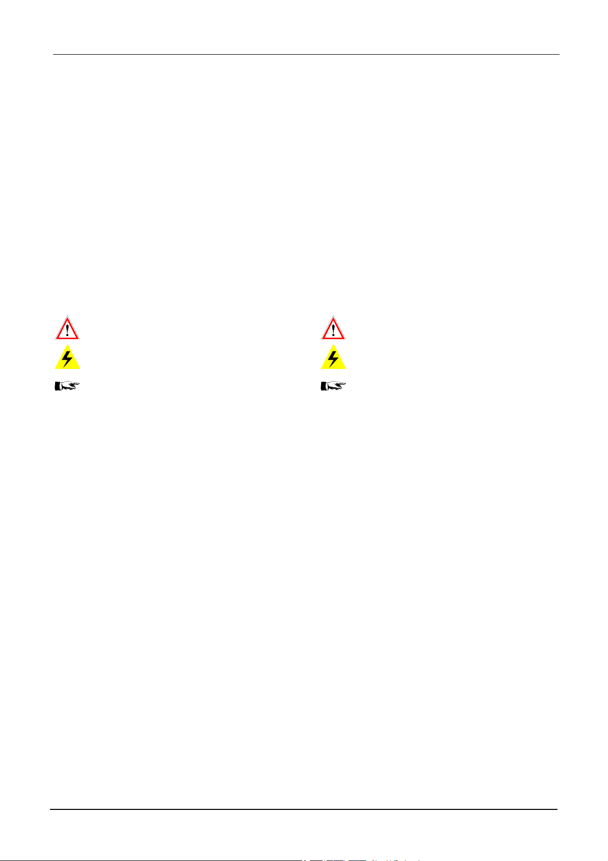
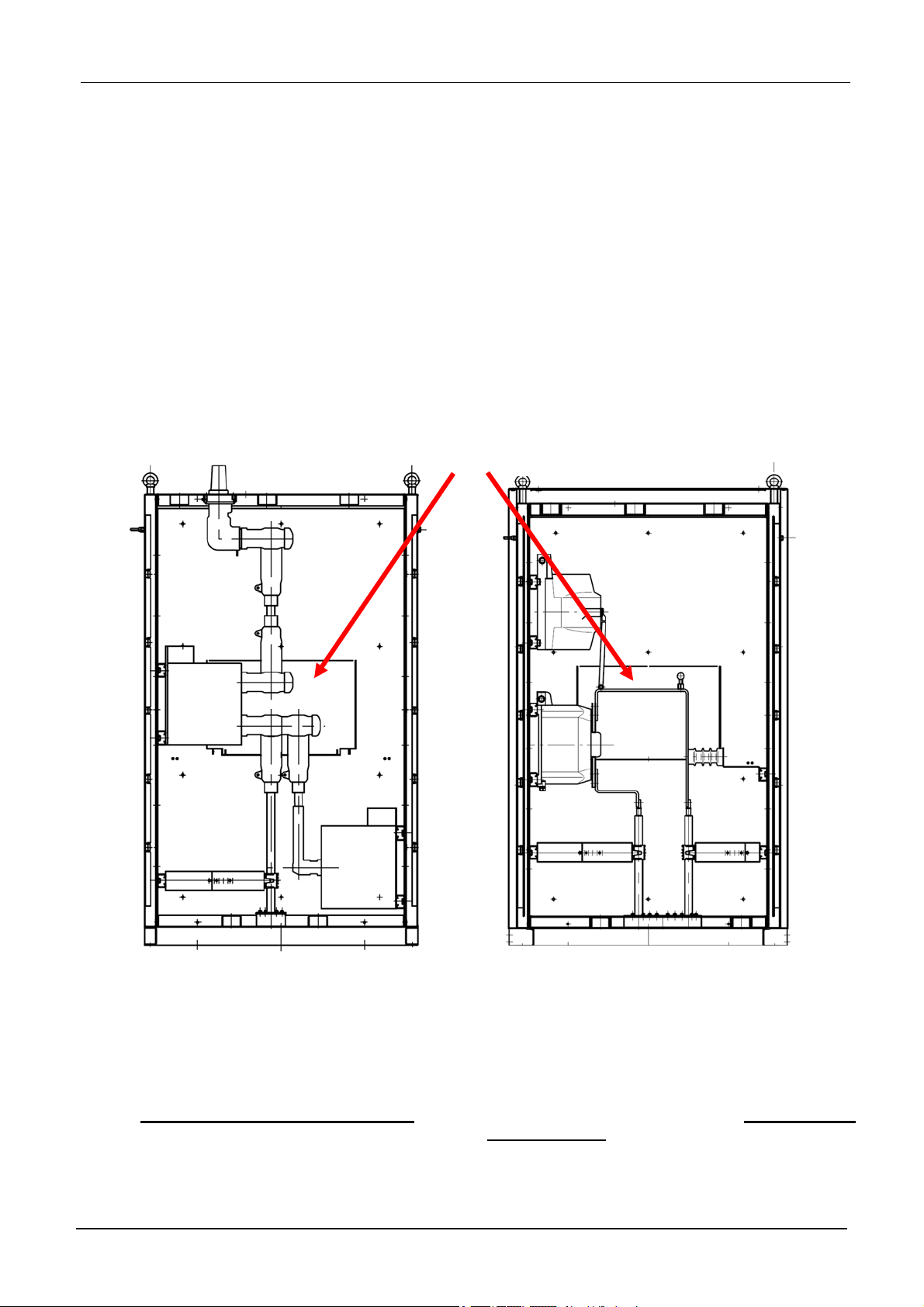
In der Rückwand des Kabelanschlussraumes befindet
sich eine Sensorklappe. Bei einem Störlichtbogen im
Kabelanschlussraum wird die Sensorklappe durch die
entstehende erste Druckwelle aktiviert und löst über
einen Bowdenzug die vorgespannten Erdungsschalter aus.
Sensorklappe mit Bowdenzug
Hinweisschild Berühren
verboten
Sensor flap with Bowden wire
label Do not touch
ABS in the cable connection compartment:
- optimum protection of persons, objects and
environment
- no pressure wave to the substation
There is a sensor flap in the rear wall of the cable connection compartment. In case of an arc in the cable
connection compartment, this flap is activated caused
by the arising first pressure wave and the pre-loaded
earthing switches are operated via a Bowden wire,
© DRIESCHER • WEGBERG
© DRIESCHER • WEGBERG
Um eine unsachgemäße Auslösung des Anti-Berst
Systemes zu verhindern, ist die Sensorklappe mit
dem Verbotszeichen – „Berühren verboten“ gemäß
DIN 4844-2 DGUV Vorschrift 9 versehen.
In order to avoid an improper activation of the antiburst system, the sensor flap shows the prohibition
sign to DIN 4844-2 DGUV standard 9 “Do not touch”
Ein versehentliches Auslösen des
DRIESCHER-ABS
unter normalen Arbeitsbedingungen nicht
möglich.
®
durch den Bediener, ist
Sollte es dennoch zu einem Auslösen des ABS kommen, nehmen sie Kontakt zu unserem Kundendienst
auf.
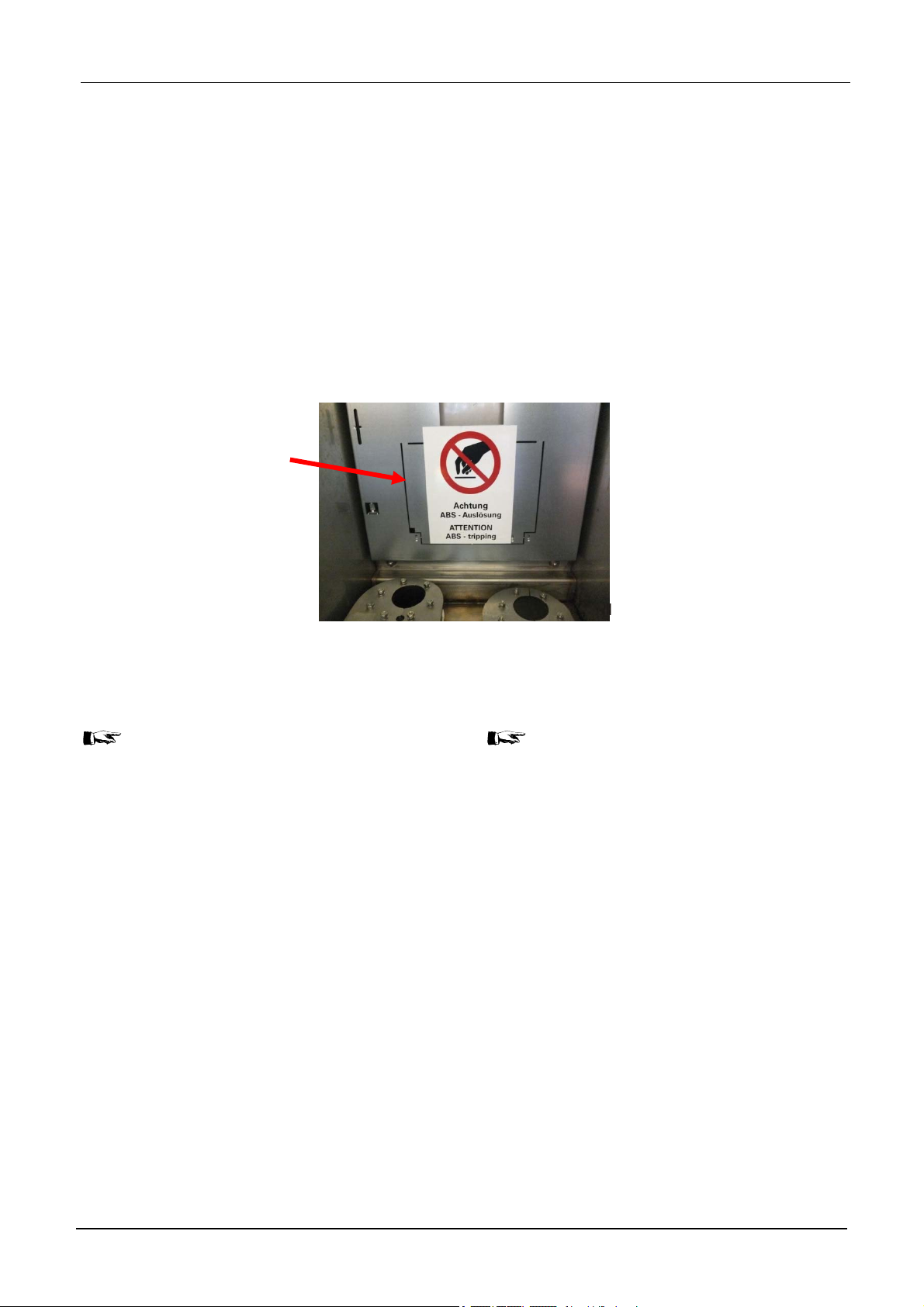
Das Ansprechen des ABS wird über einen Blitzpfeil in
der Frontblende der Schaltanlage angezeigt.
However, should same happen notwithstanding the
above, so please contact our customer service.
The ABS operation can be noticed via high-voltage
flash at front cover of the switchgear.
An unforeseen activation of the
DRIESCHER-ABS
normal working conditions.
®
is not possible under
12
MINEX®-C ABS zero
(DE-EN)
DRIESCHER WEGBERG
Graues Anzeigefeld: ungestörter Betrieb
Grey display: correct operation
Gelbes Anzeigefeld mit Blitzpfeil:
ABS hat angesprochen.
Anlage außer Betrieb nehmen
Yellow display with high-voltage flash:
ABS has operated.
Put switchgear out of operation.
© DRIESCHER • WEGBERG
Die manuelle EIN- und AUS-Schaltung kann bei vorgespanntem Antrieb wie üblich vorgenommen werden. Lasttrennschalter und Erdungsschalter sind in
der Standardausführung gegeneinander verriegelt.
Die Verriegelung lässt allerdings die EIN-Schaltung
des Erdungsschalters zur Störlichtbogenbegrenzung,
über die ABS-Sensoren, unabhängig vom Schaltzustand der Gesamtanlage zu.
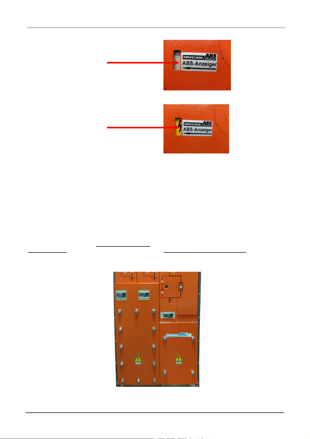
Die Schaltfelder von MINEX-C ABS
®
zero Anlagen
sind mit Kabelraumblenden ausgestattet, die den Kabelanschlussraum druckdicht verschließen. Dazu
werden die Verschließungen mit einem Anzugsmo-
ment von 50Nm festgezogen.
Somit wird gewährleistet, dass kein Druck aus dem
Kabelanschlussraum entweichen kann.
The manual ON-and OFF switching operation can be
performed as usual under pre-loaded energy storing
device. As standard design, switch-disconnector and
earthing switch are mechanically interlocked against
each other. However, the interlocking allows the closing operation of the earthing switch for limitation of the
internal arc via the ABS sensors, and this independent
of the switch position of the complete switchgear.
The cubicles of switchgear type MINEX-C ABS
are equipped with cable compartment covers which
provide a pressure-tight sealing of the cable compartment. For that purpose, the closures are tightened
with a tightening torque of 50Nm.
Therefore it is guaranteed, that no pressure can escape from the cable connection compartment.
®
zero
MINEX
© DRIESCHER • WEGBERG
®
-C ABS zero (DE-EN) 13
DRIESCHER WEGBERG
©
ABS im luftisolierten Messfeld:
- Optimaler Personen-, Sach- und Umweltschutz
- Keine Druckwelle auf umgebende Stationsbauteile
Das Prinzip der ABS-Auslösung über Bowdenzug
wurde auch auf das Messfeld übertragen.
Auch hier befindet sich in der Rückwand des Messfeldes eine Sensorklappe. Bei einem Störlichtbogen im
Messfeld wird die Sensorklappe durch die entstehende erste Druckwelle aktiviert und löst über einen
Bowdenzug die vorgespannten Erdungsschalter aus.
Sensorklappe mit Bowdenzug/
Sensor flap with Bowden cable
ABS in the air-insulated metering cubicle:
- optimum protection of persons, objects and
environment
- no pressure wave to the substation
The principle of the ABS release via bowden cable
was also transferred to the metering cubicle.
Here also a sensor flap is located in the rear wall of
the metering cubicle. In case of an internal arc in the
metering cubicle the sensor flap is activated by the
first rising pressure wave and releases via bowden
cable the pre-loaded earthing switch.
Variante 1: 12-36kV mit metallgekapselten Wandlern/
Version 1: 12-36kV with metal-enclosed transformers
Die Messfelder von Driescher ABS® zero Anlagen
sind mit Blenden ausgestattet, die das Messfeld
druckdicht verschließen. Dazu werden die Verschließungen mit einem Anzugsmoment von 50Nm festgezogen.
Somit wird gewährleistet, dass kein Druck aus dem
Messfeld entweichen kann.
DRIESCHER • WEGBERG
The metering cubicles of switchgears type Driescher
ABS® zero are equipped with covers which close the
metering cubicle pressure-sealed.
Therefore the closures are fastened with a bolting
torque of 50Nm.
Therefore it is guaranteed, that no pressure can escape from the metering cubicle.
Variante 2: 12kV mit Gießharzwandlern/
Version 2: 12kV with cast resin transformers
14
MINEX®-C ABS zero
(DE-EN)
DRIESCHER WEGBERG
©
Kapazitive Schnittstelle
Spannungsfreiheit feststellen über die kapazitive
Schnittstelle nach VDE 0682 Teil 415
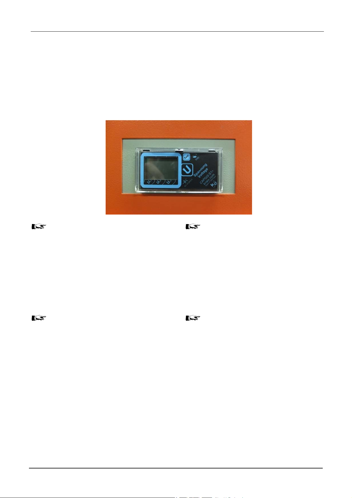
Integriertes Spannungsanzeigegerät
Standardmäßig sind integrierte Spannungsanzeigegeräte zur Feststellung der Spannungsfreiheit nach
VDE 0682 Teil 415 eingebaut.
Capacitive Interface
Verify the isolation from supply via the capacitive
interface according to IEC 61243-5.
Integrated voltage indication device
Integrated voltage indication devices are installed as a
standard to verify the isolation from supply according
to IEC 61243-5.
DRIESCHER • WEGBERG
Mit integrierten Spannungsanzeige-systemen entfällt die Wiederholungsprüfung. Bitte
beachten Sie hierzu die entsprechende Bedienungsanleitung.
Spannungsfreiheit feststellen über HR-Schnittstelle
Die Prüfung auf Spannungsfreiheit nach HR-System
(70...90 V am Messpunkt bei 2,5 A) erfolgt mit kapa-
zitiven Spannungsanzeigegeräten an den Messbuchsen L1, L2, L3.
Benutzen Sie nur Prüfgeräte nach VDE
0682 Teil 415 für HR-Systeme. Beachten
Sie die Betriebsanleitung der Prüfgerätehersteller und VDE 0682 Teil 415. Prüfen Sie
die Prüfgeräte vor Gebrauch auf Funktion!
Verify the isolation from supply via HR- interface
The check for isolation from supply according to the
HR-system (70…90 V at the measuring point with 2,5
A) is performed with capacitive voltage indicators on
the measuring sockets L1, L2, L3.
-
Vor der Prüfung:
-
Schutzstöpsel entfernen
-
Spannungsanzeigegerät nach Betriebsanleitung des Herstellers mit Messbuchsen verbinden und auf Spannungsfreiheit prüfen.
-
Nach der Prüfung:
-
Spannungsanzeigegerät von den Messbuchsen trennen.
-
Schutzstöpsel auf Messbuchsen stecken, um
das Verschmutzen der Messbuchsen zu verhindern.
-
-
With integrated voltage indication system, the
repeat test is omitted. Please observe the corresponding operation instruction.
Only use test instruments corresponding to
IEC 61243-5 for HR Systems. Observe the
operating manual issued by the manufacturer of the test instruments and IEC 61243-
5. Check the test instruments for proper operation before usage!
Before the check:
-
Remove the protective caps.
-
Connect the voltage indicator according to the
operating manual of the manufacturer with the
measuring sockets and check, if the switchgear is dead.
After the check:
-
Separate the voltage indicator from the measuring sockets.
-
Put the protective caps onto the measuring
sockets to avoid the formation of dirt.
MINEX®-C ABS zero
(DE-EN)
15
DRIESCHER WEGBERG
g p
Keine Kurzschlussstecker verwenden! Die
Schutzfunktion der spannungsbegrenzenden Sollbruchstelle wird bei Verwendung
von Kurzschlusssteckern unwirksam!
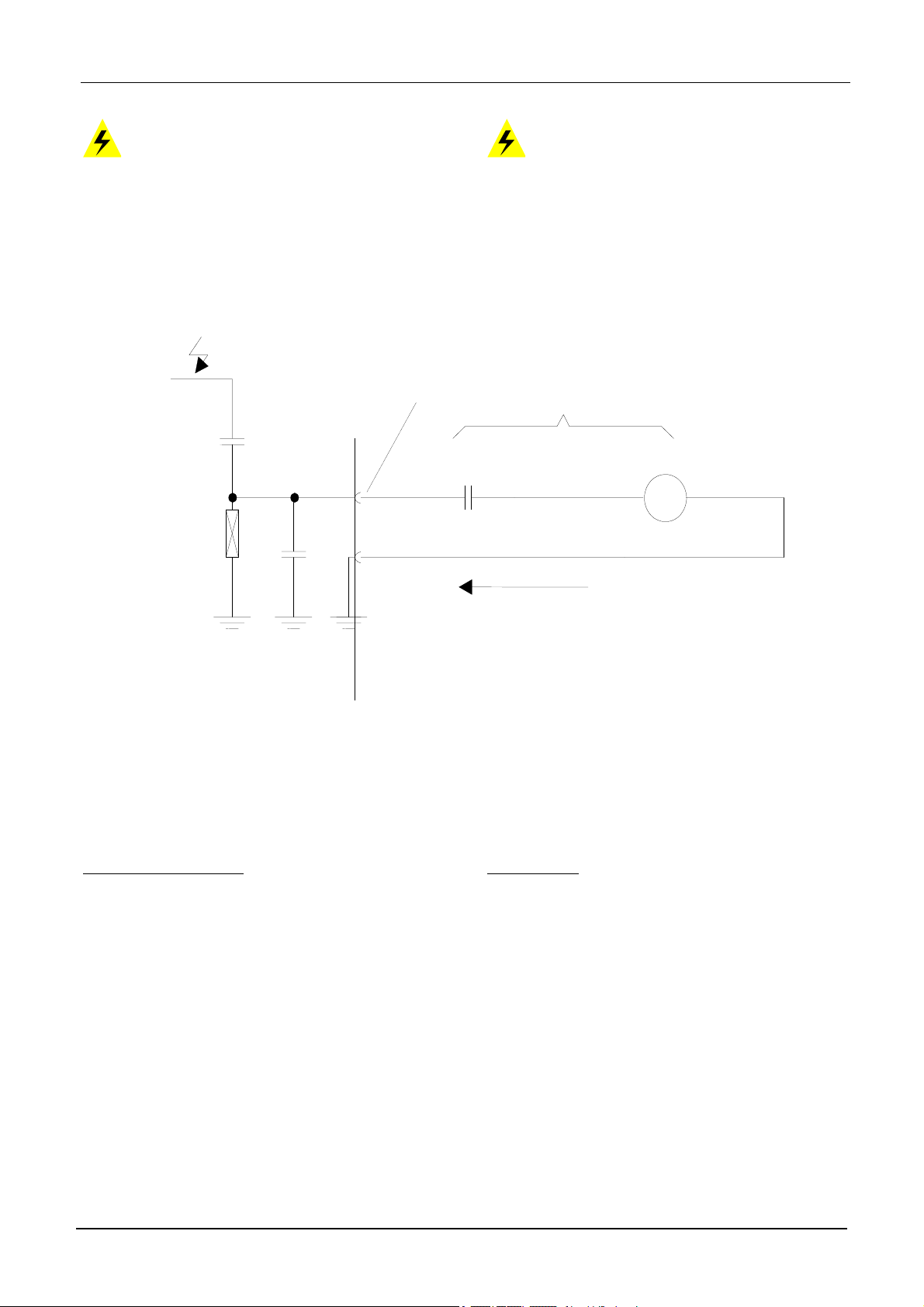
Messaufbau zur Wiederholungs-/ Funktionsprüfung nach VDE 0682 Teil 415 Abschnitt 5.26.2
U
Messpunkt /
Measurin
Measuring arrangement for the Repeat / Functional Test according to IEC 61243-5, Subclause
5.26.2
oint
C
M
Do not use any shorting plugs! The protective function of the declared breaking point
that limits voltage becomes invalid with the
use of shorting plugs.
Z
R
i
µA
Messstrom /
measuring current I
Koppelteil/
Coupling part
Wiederholungsprüfung: In festen Zeitabständen
durch o.g. Funktionsprüfung bei bekannter Betriebsspannung. (Letzte Wiederholungs- / Funktionsprüfung siehe Aufdruck am Koppelteil).
Z = 36 M
I
2,5 A*U/[3*(0,45UN)]
M
Bei U = U
at U = U
folgt IM 3,2 A
N
follows IM 3,2 A
N
Repeat Test: In fixed intervals with the above-mentioned functional test and a predetermined operating
voltage. (Last repeat/functional test see marking on
the coupling).
M
Messbeschaltung/
measuring circuit
16 MINEX
®
-C ABS zero (DE-EN)
DRIESCHER WEGBERG
Phasengleichheit feststellen
Führen Sie die kapazitive Phasenvergleichsmessung vor dem ersten Zuschalten eines
unter Spannung stehenden Kabels durch!
Für LR-Systeme gilt:
- Beachten Sie die entsprechende Bedienungsanleitung des Phasenprüfgeräteherstellers.
Für HR-Systeme gilt:
- Entfernen Sie die Schutzstöpsel der Messbuch-
sen.
- Verbinden Sie nacheinander Messbuchsen (L1-L1,
L2-L2, L3-L3) der betreffenden Kabelabgänge mit
dem Phasenvergleichsgerät.
- Stellen Sie die Phasengleichheit fest.
- Stecken Sie die Schutzstöpsel auf die Messbuch-
sen.
Benutzen Sie nur Prüfgeräte nach VDE
0682 Teil 415 für LR-Systeme bzw. HR-systeme. Beachten Sie die Betriebsanleitung
der Prüfgerätehersteller und VDE 0682 Teil
415. Prüfen Sie die Prüfgeräte vor Gebrauch
auf Funktion!
Check the Phase Parity
Valid for LR-systems:
- The corresponding operating instructions is sued by the manufacturer of the phasing tester
have to be observed
Valid for HR-systems:
- Remove the protective caps from the measuring
- Subsequently connect measuring sockets (L1-L1,
- Check the phase parity.
- Put the protective caps onto the measuring sock-
Carry out the capacitive phase comparison
test before the first connection of a live cable
is performed!
sockets.
L2-L2, L3-L3) of the corresponding cable ends
with the phase comparison test device.
ets.
Please only use test devices according to
IEC 61243-5 for LR-Systems resp. HR-systems. Please observe the instructions issued by the manufacturer of the test equipment and IEC 61243-5. Check the test instruments for proper operation before usage!
MINEX
®
-C ABS zero (DE-EN) 17
DRIESCHER WEGBERG
©
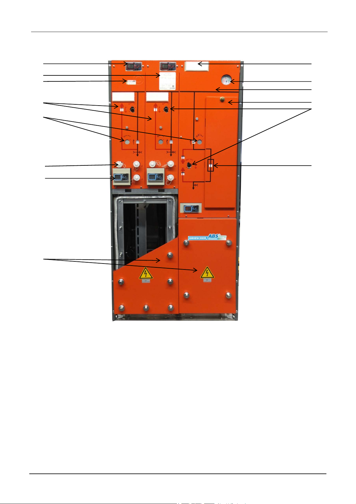
Übersicht
12
Overview
9
8
13
1 3
5
14 10
7
11
2
6
4
DRIESCHER • WEGBERG
1. Kabelschaltfeld
2. Transformatorschaltfeld
3. Sicherungsblende
4. Kabelanschlussraumblende MINEX-C ABS
zero
5. Antriebsbuchse für Lasttrennschalter
6. Antriebsbuchse für Erdungsschalter
7. Integriertes Spannungsanzeigegerät (VDS)
8. Leistungsschild
9. Beschriftungsschild
10. Blindschaltbild mit Schaltstellungsanzeige
11. Manometer oder Sollfunkenstrecke (Option)
12. Kurzschlussanzeiger (Option)
13. Anzeige des Anti-Berst-Systems (ABS)
14. Galvanischer Zugriff hinter der Kabelanschluss-
raumblende
®
1. cable cubicle
2. transformer cubicle
3. fuse cover
4. cable connection compartment MINEX –C
5. drive socket for switch-disconnector
6. drive socket for earthing switch
7. Integrated voltage indication device (VDS)
8. name plate
9. label
10. mimic diagram with switch position indication
11. manometer or spark plug (option)
12. short circuit indicator (option)
13. display for ABS tripping
14. galvanic connection for cable testing behind
the cover of cable compartment
ABS
®
zero
18 MINEX
®
-C ABS zero (DE-EN)
DRIESCHER WEGBERG
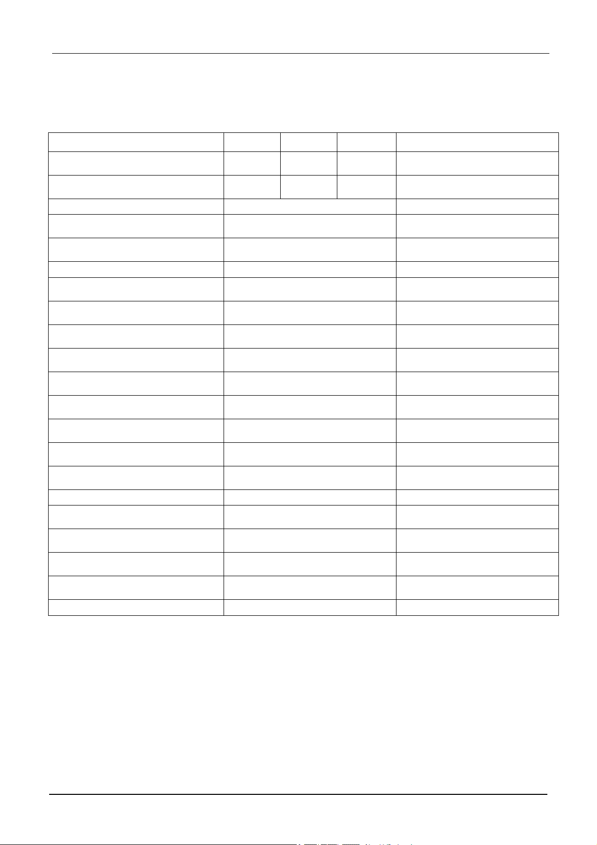
Technische Daten
Bemessungsgrößen
Bemessungsspannung 12 kV 17,5 kV 24 kV Rated voltage
Bemessungs-Kurzzeit-Stehwechsel-
spannung
Bemessungs-Stehblitzstoßspannung 75/85 kV 95/110 kV 125/145kV
Bemessungsfrequenz 50/60 Hz Rated frequency
Bemessungsbetriebsstrom für
Kabelschaltfelder
Bemessungsbetriebsstrom für
Transformatorschaltfelder
Bemessungs-Kurzzeitstrom 20 kA Rated short-time current
Bemessungs-Stoßstrom für
Kabelschaltfeld
Bemessungs-Stoßstrom für
Transformatorschaltfeld
Bemessungs-Kurzschlusseinschaltstrom
Bemessungs-Netzlastausschaltstrom
Bemessungs-Leitungsringausschaltstrom
Bemessungs-Kabelausschaltstrom 60 A
Bemessungs-Freileitungsausschalt-
strom
Bemessungs-
Erdschlussausschaltstrom
Bemessungs-Transformatorausschaltstrom
Störlichtbogenqualifikation IAC AFLR 20kA 1s Internal Arc Classification
Klassifizierung der mechanischen
Lebensdauer
Klassifizierung der elektrischen Lebensdauer
Klassifizierung der mechanischen
Lebensdauer Erder
Klassifizierung der elektrischen Lebensdauer Erder
Zulässige Umgebungstemperaturen -25°C +60°C **** Admissible ambient temperatures
bis Sicherungseinsatz
*
mit Überbrückungseinsatz. Mit HH-Sicherung ist der Bemes-
**
sungsstrom abhängig vom eingesetzten Sicherungstyp.
maximaler Durchlassstrom der HH-Sicherung
***
bei Umgebungstemperaturen >40°C Reduktionsfaktoren be-
****
rücksichtigen
28/32 kV 38/45 kV 50/60 kV
Klasse M1 / class M1
Klasse E3 / class E3
Klasse M0 / class M0
Klasse E2 / class E2
Technical Data
Rated values
Rated short-duration power
frequency withstand voltage
Rated lightning impulse
withstand voltage
630 A
630 A * / 200 A **
50 kA
50 kA ***
Rated peak withstand current for
Rated short-circuit peak withstand
50 kA Rated short-circuit making current
630 A
630 A
10 A
Rated mainly active load breaking
Rated distribution line closed-loop
Rated line charging breaking cur-
300 A Rated earth fault breaking current
10 A
Classification of the mechanical
Classification of the electrical en-
Classification of the mechanical
Classification of the electrical en-
up to HRC fuse
*
with solid link, in use with HRC-fuses the rated current de-
**
pends on the installed fuse type
maximum cut-off current of HRC-fuse
***
at ambient temperatures >40°C take care of the reduction fac-
****
tors
Rated normal current for
cable cubicles
Rated normal current for
transformer cubicles
cable cubicle
current for transformer cubicle
breaking current
Rated cable charging breaking
Rated no-load transformer
breaking current
endurance of earthing switch
durance of earthing switch
current
current
rent
endurance
durance
MINEX
®
-C ABS zero (DE-EN) 19
DRIESCHER WEGBERG
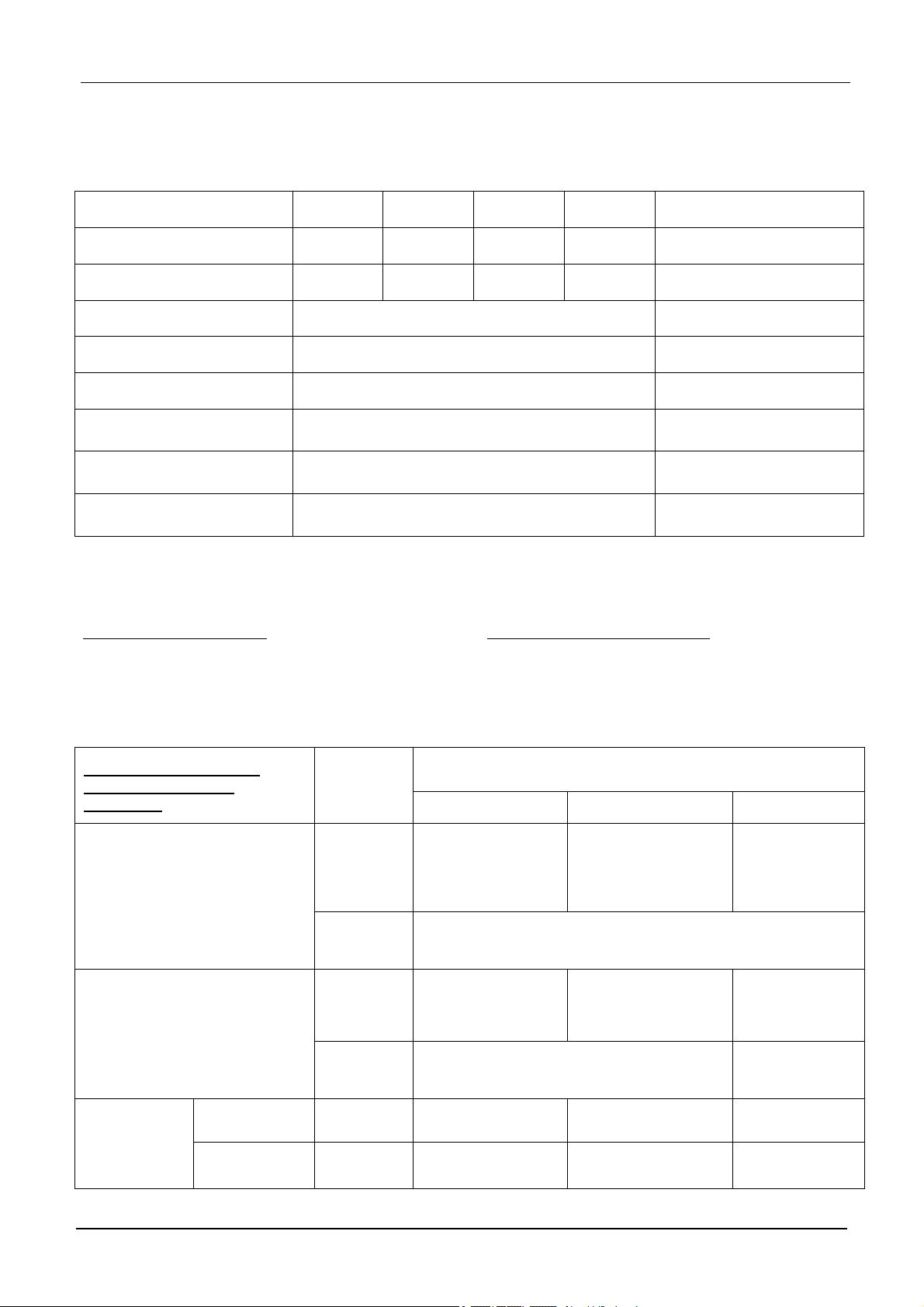
Technische Daten Messfeld Driescher ABS® zero 12-36kV Bauhöhe 1700
®
Technical Data Metering Cubicle Driescher ABS
Bemessungs-Kurzzeit-Stehwechselspannung
Bemessungs-Stehwechselspannung
Bemessungs-Stehblitzstoßspannung
Bemessungsfrequenz 50/60 Hz Rated frequency
Bemessungsbetriebsstrom 630 A Rated normal current
Bemessungs-Kurzzeitstrom 20 kA Rated short-time current
12 kV 17,5 kV 24 kV 36 kV Rated voltage
28/32 kV 38/45 kV 50/60 kV 70/80 kV
75/85 kV 95/110 kV
125/145
kV
zero 12-36kV Height 1700
Rated short-duration power
frequency withstand voltage
170/195
kV
Rated lightning impulse
withstand voltage
Bemessungs-Stoßstrom 50 kA
Rated peak withstand
current
Störlichtbogenqualifikation IAC AFLR 20kA 1s Internal Arc Classification
Zulässige
Umgebungstemperaturen
-25°C bis +60°C *
Admissible ambient
temperatures
bei Umgebungstemperaturen >40°C Reduktionsfaktoren be-
*
rücksichtigen
nur für Variante 1 mit metallgekapselten Wandlern
**
at ambient temperatures >40°C take care of the reduction fac-
*
tors
only for type 1 with metal-enclosed transformers
**
Hinweis zu Messwandlern:
Das Driescher ABS zero Messfeld gibt es nur mit folgenden Wandlern:
Variante 1: 12kV-36kV
Mit metallgekapselten bzw. metallisierten Messwandlern.
Wandler ohne Eichung /
Transformer without
calibration
Hersteller/
Manufacturer
ELEQ
Stromwandler /
Current transformers
Typ/type C (630A)
Ritz
12D2-C Außen-
Hint for instrument transformers:
The Driescher ABS zero metering cubicle is only available with the following transformers:
Version 1: 12kV-36kV
With metal-enclosed resp. metal-plated instrument
transformers.
Typ (metallgekapselt bzw. metallisiert)/
Type (metal-enclosed resp. metal-plated)
12kV 24kV 36kV
IGWCAK
konus/
External cone
IGWCAK
24D2-C Außenkonus/
External cone
Typ/type C (630A)
GBWA 12…36
Gr. 1…3 Außenkonus/external cone Typ/type A, B, C
-
UGECAK
12D2 Außenkonus/
external cone
Typ/type A (250A)
GBEAN 12/0…24/0 Außenkonus/external
cone Typ/type A, B, C
KGBEA12 KGBEA24 KGBEA36
Spannungswandler /
Voltage transformer
Kombiwandler /
Außenkonus /
external cone
ELEQ
Ritz
Ritz
combined instrument
transformer
Innenkonus /
internal cone
Ritz
KGBEI12 KGBEI24 KGBEI36
20 MINEX
®
-C ABS zero (DE-EN)
UGECAK
24D2 Außenkonus/
external cone
Typ/type A (250A)
-
-
 Loading...