

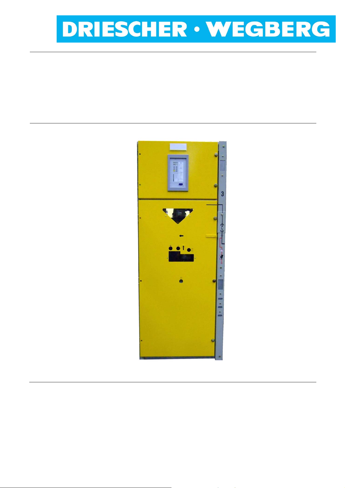
Leistungsschalterfeld
Circuit-breaker cubicle
Typ / Type LDTM 12/24 kV
Zusatz zur Montage- und Betriebsanleitung
Addition to Operating Manual
DRIESCHER WEGBERG
MittelspannungsLastschaltanlage Typ LDTM
mit Leistungsschalter
Bemessungsspannung bis 24kV
Bemessungsstrom bis 630A
Medium voltage
switchgear type LDTM
with circuit-breaker
Rated voltage up to 24kV
Rated current up to 630A
01/2016

DRIESCHER WEGBERG
Alle Rechte vorbehalten / All rights reserved
DRIESCHER WEGBERG 2016
2 LDTM Leistungsschalterfeld / Circuit-breaker cubicle – SION -12-24kV
DRIESCHER WEGBERG
INHALT CONTENTS
Inhalt 3 Contents 3
Sicherheitsvorschriften 4 Safety Regulations 4
Allgemeine Information 5 General Information 5
Bestimmungsgemäße Verwendung 5 Intended Use 5
Qualifiziertes Personal 5 Qualified Personnel 5
Normen und Vorschriften 6 Standards and Specifications 6
Betriebsbedingungen 7 Operating Conditions 7
Haftungsbeschränkungen 7 Liability Limitations 7
Beschreibung 8 Description 8
Zu dieser Anleitung 8 About this Manual 8
Allgemeines 9 General 9
Verriegelungen 10 Interlockings 10
Übersicht 11 Overview 11
Technische Daten 13 Technical Data 13
Montage 14 Assembly 14
Herausnahme des Leistungsschalters 15 Removal of Circuit-Breaker 15
Elektrischer Anschluss 16 Electrical Connection 16
Betrieb 16 Operation 16
Schaltvorgänge 16 Switching Operations 16
Schalten des Erdungsschalters 16 Switching of Earthing Switch 16
Verfahren des Leistungsschalters 17 Move of the Circuit-Breaker 17
Schalten des Leistungsschalters 17 Switching the Circuit-Breaker 17
Schaltfolge einer Kurzunterbrechung 18 Switching Sequence of an Auto-Reclosing 18
Instandhaltung 19 Maintenance 19
Wartungsanleitung 19 Maintenance Manual 19
Entsorgung 21 Waste Disposal 21
Abmessungen und Gewicht 22 Dimensions and Weight 22
Besonderer Hinweis!
Sie haben eine luftisolierte Schaltanlage Typ
LDTM erworben, in der ein oder mehrere
Leistungsschalterfelder integriert sind. Diese
vorliegende Montage- und Betriebsanleitung
gibt lediglich spezielle Hinweise zur Handhabung und Bedienung der Leistungsschalterfelder und darf ausschließlich in
Zusammenhang mit der Montage- und
Betriebsanleitung der Schaltanlage Typ
LDTM und der Betriebsanleitung des
Siemens Leistungsschalters Typ SION, in der
die allgemeine Handhabung und Bedienung
beschrieben ist, angewendet werden.
Special hint!
You have bought an air-insulated
switchgear type LDTM with one or more
integrated circuit-breaker cubicles. This
operating manual only gives hints for the
use and operation of the circuit-breaker
cubicles and must only be used together
with the operating manual of the
switchgear type LDTM and the operating
manual of the Siemens circuit-breaker
type SION, in which the general use and
operation is described.
LDTM Leistungsschalterfeld / Circuit-breaker cubicle – SION – 12-24kV 3
DRIESCHER WEGBERG
Sicherheitsvorschriften
Die in der Montage- und Betriebsanleitung
enthaltenen Hinweise zu
- Transport
- Montage
- Inbetriebnahme
- Bedienung
- Wartung
der Mittelspannungs-Schaltanlage müssen unbe-
dingt beachtet werden.
Wichtige sicherheitstechnische Hinweise sind durch
folgende Symbole gekennzeichnet. Befolgen Sie
diese Hinweise, um Unfälle und Beschädigungen der
Mittelspannungs-Schaltanlage zu vermeiden.
Warnung vor einer Gefahrenstelle!
Warnung vor elektrischer Spannung!
Besondere Hinweise!
Safety Regulations
It is imperative that the notes in these Operating
Instructions regarding
- transport
- assembly
- setting to work
- operation
- maintenance jobs
of the medium voltage switchgear are adhered to.
Important instructions such as safety notes are
identified by means of the following symbols. Follow
these notes to avoid accidents and damage involving
the medium voltage switchgear.
Warning of a danger area!
Warning of electrical voltage!
Special hints!
Diese Symbole finden Sie bei allen Hinweisen in
dieser Betriebsanleitung, bei denen Verletzungsoder Lebensgefahr besteht.
Beachten Sie diese Hinweise und geben Sie diese
an anderes qualifiziertes Personal weiter. Neben
diesen Hinweisen sind
- Sicherheitsvorschriften,
- Unfallverhütungsvorschriften,
- Richtlinien und anerkannte Regeln der Technik,
sowie sämtliche Instruktionen dieser Montage- und
Betriebsanleitung zu beachten!
You will find these symbols with all hints given in this
manual, where risk of injury or danger of live exists.
Comply with these notes and pass them on to other
qualified electrical technicians. Aside from these
notes, comply with
- Safety specifications
- Accident prevention regulations
- Guidelines and recognized rules of technology
as well as all instructions and notes in these
Operation and Assembly Instructions!
4 LDTM Leistungsschalterfeld / Circuit-breaker cubicle – SION -12-24kV

DRIESCHER WEGBERG
Allgemeine Information
Bestimmungsgemäße Verwendung
Das DRIESCHER-LDTM-Leistungsschalterfeld ist
ein typgeprüftes Mittelspannungs-Leistungsschalterfeld für Innenraumanwendung mit einem VakuumLeistungsschalter in Einschubtechnik.
Der einwandfreie und sichere Betrieb der
Schaltanlage setzt voraus:
Sachgemäßer Transport und fachgerechte
Lagerung
Fachgerechte Montage und Inbetriebnahme
Sorgfältige Bedienung und Instandhaltung durch
qualifiziertes Personal
Die Beachtung dieser Anleitung
Die Einhaltung der am Aufstellungsort geltenden
Aufstellungs-, Betriebs- und Sicherheitsbestimmungen
Eine andere oder darüber hinausgehende Verwendung gilt als nicht bestimmungsgemäß. Für hieraus
resultierende Schäden haftet der Hersteller nicht.
Das Risiko trägt allein der Betreiber/Benutzer.
General Information
Intended use
The DRIESCHER-LDTM switchgear is a typetested Medium Voltage Switchgear for indoor use
with a vacuum circuit-breaker in withdrawable-unit
design.
The proper and safe operation of the switchgear
requires the following pre-conditions:
Appropriate transport and correct storing
Professional assembly and setting to work
Accurate operation and maintenance through
The observation of this manual
The compliance with the regulations for
Another or an extended use is not regarded as
intended. The manufacturer does not guarantee for
damages resulting from it.
The risk is exclusively in the hands of the operator/
user.
Qualifiziertes Personal
Qualifiziertes Personal im Sinne dieser Anleitung
sind Personen, die mit der Aufstellung, Montage,
Inbetriebsetzung, Instandhaltung und dem Betrieb
des Produktes vertraut sind und durch ihre Tätigkeit
über entsprechende Qualifikationen verfügen, wie
z.B.:
Ausbildung und Unterweisung bzw.
Berechtigung, Stromkreise und Geräte/Systeme
gemäß den Standards der Sicherheitstechnik
ein- und auszuschalten, zu erden und zu
kennzeichnen.
Ausbildung oder Unterweisung gemäß den
Standards der Sicherheitstechnik in Pflege und
Gebrauch angemessener Sicherheitsausrüstung.
Schulung und Erste Hilfe zum Verhalten bei
möglichen Unfällen.
Qualified personnel
Qualified people in accordance with this manual are
professionals, being familiar with the installation,
assembly, setting to work, maintenance and
operation of this product and those who have the
relevant qualifications, i.e.
Education and instruction as well as
Education or training according to the
Training and First Aid for the behaviour with
qualified people
installation, operation and safety, valid at site.
authorised permission to switch ON and OFF,
to earth and to mark circuits and devices/
systems according to the standards of safety
engineering.
standards of safety engineering in care and
use of adequate safety equipment.
possible accidents.
LDTM Leistungsschalterfeld / Circuit-breaker cubicle – SION – 12-24kV 5

DRIESCHER WEGBERG
Normen und Vorschriften
Vorschrift der Berufsgenossenschaft
DGUV Vorschrift 1 Grundsätze der Prävention DGUV standard 1 Basics of prevention
Standards and specifications
Specifications of the German Trade Association
DGUV Vorschrift 3 Elektri sche Anlage n und
Betriebsmittel
DGUV standard 3 Electrical systems and
Equipment
DIN/VDE-Bestimmungen Standards
DIN VDE 0101 Errichten von Starkstrom-
anlagen mit Nennspannungen
über 1kV
DIN VDE 0105 Betrieb von elektrischen
Anlagen
VDE 0670 Teil 4 Hochspannungssicherungen IEC 60282-1 High-voltage fuses
VDE 0671 Teil 1 Gemeinsame Bestimmungen
für HochspannungsSchaltgeräte-Normen
VDE 0671 Teil 100 Wechselstrom-
Leistungsschalter
VDE 0671 Teil 102 Wechselstromtrennschalter
Erdungsschalter
VDE 0671 Teil 103 Hochspannungs-Lastschalter IEC 62271-103 High-voltage switches
DIN VDE 0101 Power installations exceeding
AC 1kV
EN 50110-1 Operation of electrical
installations
IEC 62271-1 Common specifications for high-
voltage switchgear and
controlgear standards
IEC 62271-100 Alternating-current circuit-
breakers
IEC 62271-102 Alternating current disconnec-
tors and earthing switches
VDE 0671 Teil 105 Hochspannungs-Lastschalter-
Sicherungs-Kombination
VDE 0671 Teil 200 Metallgekapselte Wechsel-
strom-Schaltanlagen für
Bemessungsspannungen über
1kV bis einschließlich 52kV
VDE 0682 Teil 415 Spannungsprüfsystem IEC 61243-5 Voltage detecting systems
IEC 62271-105 High-voltage alternating current
switch-fuse combination
IEC 62271-200 Alternating current metal-
enclosed switchgear and
controlgear for rated voltages
above 1kV and up to and
including 52kV
6 LDTM Leistungsschalterfeld / Circuit-breaker cubicle – SION -12-24kV

DRIESCHER WEGBERG
Betriebsbedingungen
Normale Betriebsbedingungen
Das Leistungsschalterfeld ist für normale
Betriebsbedingungen von Innenraum-Schaltgeräten
und –Schaltanlagen bei folgenden Umgebungstemperaturen ausgelegt:
Höchstwert +60 °C*
Tiefstwert -25 °C
Sonder-Betriebsbedingungen
Nach VDE 0671 Teil 1 können von den normalen
Betriebsbedingungen abweichende Betriebsbedingungen zwischen Hersteller und Betreiber vereinbart werden. Zu jeder Sonder-Betriebsbedingung
muss der Hersteller vorher befragt werden.
* bei Umgebungstemperaturen > 40°C Reduktionsfaktoren
berücksichtigen
Haftungsbeschränkungen
Alle in dieser Montage- und Betriebsanleitung
enthaltenen technischen Informationen, Daten und
Hinweise für die Installation, Bedienung und Wartung
der Schaltanlage entsprechen dem Stand der
Drucklegung und erfolgen unter Berücksichtigung
unserer bisherigen Erfahrungen und Erkenntnisse
nach bestem Wissen.
Für etwaige Fehler oder Unterlassungen haften wir
unter Ausschluss weiterer Ansprüche im Rahmen
der im Hauptvertrag eingegangenen Mängelhaftungsverpflichtungen. Ansprüche auf Schadensersatz, gleich aus welchem Rechtsgrund derartige
Ansprüche hergeleitet werden, sind ausgeschlossen,
soweit sie nicht auf Vorsatz oder grober
Fahrlässigkeit beruhen.
Operating Conditions
Standard operating conditions
The circuit-breaker cubicle is designed for normal
service conditions of indoor switches and indoor
switchgears at the following ambient temperatures:
Maximum value + 60°C*
Lowest value -25° C
Special operating conditions
In accordance with IEC 62271-1, the manufacturer
and the user can agree to operating conditions that
deviate from the standard conditions. The
manufacturer must be asked in advance about any
special service condition.
* at ambient temperatures > 40°C take care of the reduction
factors
Restrictions on Liability
All technical information, data and notes for the
installation, operation and maintenance of the
medium voltage switchgear contained in these
Operation and Assembly Instructions are current as
of the day of printing and are stated to the best of our
knowledge on the basis of our experience and knowhow.
We accept liability for any errors or omissions, to
the exclusion of further claims, within the scope
of the agreed warranty. Claims for compensation
for damage are excluded, regardless of the
legal basis for those claims, unless they are
the result of intent or gross negligence.
Translations are made to the best of knowledge.
Liability of any kind shall therefore not be accepted
for faults made in the translation even if the
operating instructions are translated by us or by a
third party. Solely the German text shall prevail.
LDTM Leistungsschalterfeld / Circuit-breaker cubicle – SION – 12-24kV 7

DRIESCHER WEGBERG
Beschreibung
Zu dieser Anleitung
Diese Anleitung enthält aus Gründen der
Übersichtlichkeit nicht sämtliche Detailinformationen
zu allen Typen des Produktes. Sie kann auch nicht
jeden denkbaren Fall der Aufstellung oder des
Betriebes berücksichtigen. Einzelheiten zur
technischen Auslegung, wie z.B. technische Daten,
Sekundäreinrichtungen, Schaltpläne, entnehmen Sie
bitte den Auftragsunterlagen.
Das Leistungsschalterfeld unterliegt im Rahmen des
technischen Fortschrittes einer ständigen Weiterentwicklung. Soweit auf den einzelnen Seiten dieser
Anleitung nichts anderes vermerkt ist, bleiben
Änderungen der angegebenen Werte und
Abbildungen vorbehalten. Alle Maße sind in mm
angegeben.
Wenn Sie weitere Informationen wünschen oder falls
Probleme auftreten, die in der Anleitung nicht
ausführlich genug behandelt werden, fordern Sie die
Auskunft über unseren Kundendienst oder die
zuständige Vertretung an.
Geben Sie bitte bei Rückfragen oder Ersatzteilbestellungen folgende auf dem Typenschild
angegebene Daten an:
- Stations-, Geräte-, Anlagentyp,
- Fabrikationsnummer,
- Baujahr.
Durch Angabe dieser Daten ist gewährleistet, dass
Ihnen die richtigen Informationen oder die benötigten
Ersatzteile zugehen.
Fritz Driescher KG
Spezialfabrik für Elektrizitätswerksbedarf
GmbH & Co.
Postfach 1193; 41837 Wegberg
Industriestraße 2; 41844 Wegberg
Telefon 02434 81-1
Telefax 02434 81-446
www.driescher-wegberg.de
e-mail:info@driescher-wegberg.de
Wir weisen darauf hin, dass der Inhalt dieser
Anleitung nicht Teil einer früheren oder bestehenden
Vereinbarung, oder Zusage eines Rechtsverhältnisses ist oder dieses ändern soll. Sämtliche
Verpflichtungen der Firma DRIESCHER ergeben
sich aus dem jeweiligen Kaufvertrag, der auch die
vollständige und allein gültige Mängelhaftungsregelung enthält. Diese vertraglichen Mängelhaftungsbestimmungen werden durch die Ausführungen dieser Anleitung weder erweitert noch
beschränkt.
Description
About this manual
Due to reasons of clarity this manual does not
contain all detailed information about all types of this
product. It also cannot consider every imaginable
case of installation or operation. Details regarding the
technical design, as i.e. technical data, secondary
devices, diagrams please take from the order
documents.
The circuit-breaker cubicle is within the scope of
technical progress subject to a permanent
development. As far as nothing else is noted on the
single pages of this manual, the right of changes of
the indicated values and drawings is reserved. All
dimensions are indicated in mm.
If you require more information or if problems arise,
which are not enough discussed in detail, please ask
our service department or the relevant representation
for more information.
Please indicate the following data shown on the
nameplate for queries or spare parts:
- station, switch or switchgear type,
- serial number,
- year of manufacture.
Specifying these items ensures that you will receive
the correct information or the required spare parts.
Fritz Driescher KG
Spezialfabrik für Elektrizitätswerksbedarf
GmbH & Co.
P.O. Box 1193, 41837 Wegberg
Industriestraße 2, 41844 Wegberg
Phone: 0049 2434 81-1
Fax: 0049 2434 81-446
www.driescher-wegberg.de
e-mail:info@driescher-wegberg.de
We point out that the content of this manual is not
part of a previous or existing agreement, or is a
promise of a legal relationship or shall change this.
All obligations of DRIESCHER arise from the
respective contract of sale, which includes the
complete and exclusive valid warranty regulation.
These contractual warranty regulations are neither
extended nor limited through the remarks of this
manual
8 LDTM Leistungsschalterfeld / Circuit-breaker cubicle – SION -12-24kV

DRIESCHER WEGBERG
Allgemeines
Beschreibung
Das LDTM - Leistungsschalterfeld besteht aus
- einem ausfahrbaren Vakuum-
Leistungsschalter,
- einer Verfahreinheit,
- dem am Kabelabgang angeordneten
Erdungsschalter
- und einem Anti-Berst-System (ABS)
Das LDTM- Leistungsschalterfeld in Einschubtechnik
entspricht sowohl in der technischen Konzeption als
auch in der Fertigungstechnologie dem neuesten
Stand der Entwicklung. In dem Leistungsschalterfeld
ist im oberen Bereich eine Niederspannungsnische
für Relais, Schutzschalter, Klemmleisten usw.
angeordnet. Die Abdeckblende ist mit Scharnieren
befestigt und über druckfeste Schnellverschlüsse zu
öffnen. Optional können hier verschiedene NSAnzeigegeräte integriert sein. In der Tür befinden
sich Ausschnitte für die Verfahrkurbel und die
Handbetätigung des Leistungsschalters. Links- oder
Rechtsanschlag von Tür und Blende ist möglich. In
dem rechten Holm des Feldes befindet sich sowohl
der Erderantrieb als auch das Blindschaltbild.
Optional kann ein elektrischer Stellungsanzeiger
eingebaut sein, der den Schaltzustand des
Leistungsschalters anzeigt. Alle Schalthandlungen
sind bei geschlossener Tür durchführbar. Schutzund Messwandler, sowie die Kabelanschlussfahnen
befinden sich unterhalb des Leistungsschalters.
Das LDTM- Leistungsschalterfeld kann in folgenden
Feldvarianten gebaut werden:
• Einspeisefeld oder Abgangsfeld
• Längskupplung mit oder ohne
Schutzeinrichtung.
• Übergabefeld
General
Description
The circuit-breaker cubicle type LDTM consists of
- a vacuum circuit-breaker, draw-out type,
- a moving module
- an earthing-switch connected at the cable
- and an Anti-Burst-System (ABS).
The circuit-breaker cubicle type LDTM in draw-out
design corresponds to the most recent state of
development and this regarding the technical concept
and the production technology. A recess for the L.V.
instruments like relays, protective equipments,
terminal strips, etc. is set in the top area of the circuitbreaker cubicle. The cover is fixed by means of joints
and is opened via pressure-resistant rapid locks. As
an option, various LV display devices can be installed
here. In the door there are openings for the moving
crank and the manual control for the circuit-breaker.
Door and cover can either be hinged at left or right
side. In the right rail of the cubicle there is the
earthing drive as well as the mimic diagram.
Optionally an electric position indicator can be
installed which shows the switch position of the
circuit-breaker. All switching operations can be
performed with closed door. Below the circuit-breaker
there is a recess for the protective and measuring
transformers and the terminal lugs.
The circuit-breaker cubicle type LDTM is available
in the following cubicle variants:
• as incoming or outgoing cubicle
• longitudinal coupling with or without protec tive equipment
• bus riser cubicle
exit
LDTM Leistungsschalterfeld / Circuit-breaker cubicle – SION – 12-24kV 9

DRIESCHER WEGBERG
Verriegelungen
Das Leistungsschalterfeld beinhaltet serienmäßig
folgende Verriegelungen:
• Der Leistungsschalter kann in Trenn- und
Betriebsstellung sowohl elektrisch als auch
mechanisch geschaltet werden.
• Der Leistungsschalter kann nicht im
eingeschalteten Zustand von der Trenn- in die
Betriebsstellung und umgekehrt verfahren
werden.
Beim Erdungsschalter im Leistungsschalterfeld
sind serienmäßig folgende Verriegelungen
vorhanden:
• Der Erder ist nur in Trenn- und Außenstellung
des Leistungsschalters schaltbar.
• Der Leistungsschalter kann nur bei ausgeschaltetem Erder in Betriebsstellung
verfahren werden.
Optional können folgende Verriegelungen eingebaut
sein:
• Bei Ausfall der Steuerspannung ist ein
Einschalten des Leistungsschalters elektrisch
und mechanisch nicht möglich (Einschaltsperre)
• Die Tür des Leistungsschalterfeldes kann nur
bei eingeschaltetem Erder geöffnet werden.
• Bei Leistungsschaltern mit Motorantrieb kann
eine Einschaltsperre eingebaut werden.
Schalthebel nach dem Schaltvorgang
immer aus den Antriebsöffnungen herausziehen.
Interlockings
The circuit-breaker cubicle is equipped with the
following standard interlockings:
• The circuit-breaker can be switched electrically
• In ON-position the circuit-breaker cannot
With an earthing switch in the circuit-breaker
cubicle the following interlockings are standard:
• The earthing switch can only be switched,
• The circuit-breaker can only be moved into
As an option the following interlockings can be
installed:
• With a breakdown of the control voltage a
• The door of the circuit-breaker cubicle can only
• At circuit-breakers with motor drive a closing
and mechanically in isolated and operating
position.
be operated from isolated into operating
position and reverse.
provided the circuit-breaker is in isolated and
removed position.
operating position provided the earthing switch
is in OFF-position.
making operation of the circuit-breaker is
electrically and mechanically impossible
(closing lock-out).
be opened with earthing switch in ON-position.
lock-out can be installed.
Always remove the switch crank from the
drive sockets after the switching operation.
10 LDTM Leistungsschalterfeld / Circuit-breaker cubicle – SION -12-24kV

Übersicht
Leistungsschalterfeld
DRIESCHER WEGBERG
Overview
Circuit-breaker cubicle
DRIESCHER WEGBERG
1. Beschriftungsschild
2. Niederspannungsnische
3. Einschubführung für Einschubplatte
4. Sichtscheibe
5. Bedienfeld für Leistungsschalter (siehe dazu
auch Betriebsanleitung SION)
6. Kurzschlussanzeiger (Option)
7. Blindschaltbild
7a. Mit Schaltersymbol
7b. Mit elektrischer Schalterstellungsanzeige
für Leistungsschalter (Fremdspannung
erforderlich)
8. Schalterstellungsanzeige für Erdungsschalter
9. Antriebsöffnung für Erdungsschalter
10. Messbuchsen für kap. Spannungs-/
Phasenvergleichsmessung (Option)
1. Label
2. Low-voltage recess
3. Insertion guide for insulating protective plate
4. Inspection window
5. Operating panel for circuit-breaker (see also
6. Short circuit indicator (option)
7. Mimic diagram
7a. With switch symbol
7b. With electrical switch position indication for
8. Switch position indicator for earthing switch
9. Drive opening for earthing switch
10. Measuring sockets for testing the capacitive
operating manual SION)
circuit-breaker (separate voltage source
necessary)
voltage/phase comparison (option)
LDTM Leistungsschalterfeld / Circuit-breaker cubicle – SION – 12-24kV
11

DRIESCHER WEGBERG
Türblende Door cover
12
11
15
DRIESCHER WEGBERG
11. Öffnung für Druckknopf “AUS“
12. Öffnung für Druckknopf “EIN“
13. Hebel zum Öffnen der Blende
14. Öffnung für Handkurbel zum Spannen der Einund Ausschaltfeder
15. Öffnung für Handkurbel zum Verfahren des
Leistungsschalters
11. opening for pushbutton „OFF“
12. opening for pushbutton „ON“
13. lever to open the cover
14. opening for hand crank to charge the closing
and opening spring
15. opening for hand crank to move the circuit
breaker
13
14
Bedienfeld Leistungsschalter Operating panel circuit-breaker
17
16
18
21
16. Druckknopf “AUS“
17. Druckknopf “EIN“
18. Schalterstellungsanzeige
19. Öffnung für Handkurbel
20. Federzustandsanzeige
21. Schaltspielzählwerk
16. pushbutton „OFF“
17. pushbutton „ON“
18. switch position indication
19. opening for hand crank
20. spring status indication
21. operations counter
19
20
Schaltzubehör Switching accessory
22. Verfahrkurbel
23. Handkurbel zum Spannen
der Ein- und Ausschaltfeder
24. Schaltkurbel
22
23
22. moving crank
23. hand crank for charging the
closing and opening spring
24. switch crank
24
12 LDTM Leistungsschalterfeld / Circuit-breaker cubicle – SION -12-24kV

DRIESCHER WEGBERG
Technische Daten Technical Data
Bemessungsgrößen Rated Values
Bemessungsspannung 12kV 17,5kV 24kV Rated Voltage
Bemessungs-
Stehblitzstossspannung
Bemessungs-KurzzeitStehwechselspannung
Bemessungsbetriebsstrom 630A Rated normal current
Bemessungs- Frequenz 50/60Hz Rated frequency
Bemessungs- Kurzzeitstrom 20kA Rated short-time current
Bemessungs- Kurzschlussdauer 3s Rated duration of short circuit
Bemessungs- Stossstrom 50kA Rated peak withstand current
BemessungsKurzschlussausschaltstrom
BemessungsKurzschlusseinschaltstrom
BemessungsFreileitungsausschaltstrom
BemessungsKabelausschaltstrom
Bemessungs- Schaltfolge O - 0,3s - CO - 3min - CO Rated operating sequence
Störlichtbogenqualifikation
75/85kV 95/110kV 125/145kV
28/32kV 38/45kV 50/60kV
20kA Rated short-circuit breaking curre nt
50kA Rated short-circuit making current
10A Rated line charging breaking current
50A Rated cable charging breaking current
IAC AFL
20kA 1s
optional
IAC AFL
25kA 1s
IAC AFL 20kA 1s Internal Arc Classification
Rated lightning impulse withstand
voltage
Rated short-duration power frequency
withstand voltage
Zulässige Umgebungstemperatur -25°C bis +60°C Ambient temperature
Schaltklassen E2 - M2 - C2 Rating classes
Richtwerte für die Funktionszeiten Guide values for the processing times
Einschaltzeit < 75 ms Closing time
Ausschaltzeit < 80 ms Opening time
Lichtbogenzeit < 15 ms Arcing time
LDTM Leistungsschalterfeld / Circuit-breaker cubicle – SION – 12-24kV 13

DRIESCHER WEGBERG
Montage
Transport und Lagerung
Das LDTM- Leistungsschalterfeld darf nur stehend
transportiert werden. Für Lagerung und jeglichen
Transport muss der Leistungsschalter ausgeschaltet
(Schaltstellungsanzeiger auf „0“) und die
Einschaltfeder entspannt sein (Federpeicheranzeige
auf Symbol „entspannt“). Der Leistungsschalter
muss sich in eingefahrenem Zustand befinden.
Schaltfeldverschraubung
Bei Schaltanlagen, die als Einzelzellen geliefert
werden, müssen die Einzelzellen am Aufstellungsort
ausgerichtet und entsprechend am vorderen und
hinteren Längsholm verschraubt werden (jeweils 1
Schraube M10). Anschließend müssen die
Auslösewellen des Anti-Berst-Systems (ABS)
gekuppelt werden (siehe Bedienungsanleitung für
LDTM- Anlage Kapitel: „Kuppeln der Auslösewellen
des Anti-Berst-Systems bei Einzelfeldlieferung“).
Kabelanschluss
Sämtliche Kabelanschlussstellen sind als Flachanschlüsse ausgebildet und in der Anschlusszone
typgeprüft. Geeignet sind Endverschlüsse verschiedener Fabrikate in Verbindung mit Flachkabelschuhen. Zur Erleichterung der Anschlussarbeiten
sollten die Kabel vor Aufstellung der Anlage
anschlussfertig sein. Kabelende nach Montageanweisung des Kabelgarnituren- Herstellers
absetzen und Kabelgarnituren montieren.
Die Kabelschellen zur Befestigung der
Kabel müssen unterhalb der Endverschlüsse liegen!
Assembly
Transport and Storage
The circuit-breaker cubicle type LDTM must only
be transported in an upright standing position. For
storage and any transport the circuit breaker must be
switched OFF (switch position indicator shows “0”)
and the closing spring must be released (display of
the spring storage mechanism on the symbol “without
tension”). The circuit-breaker must be in draw-in
position.
Screwing of the cubicle
With switchgears that are supplied as single cubicles,
the single cubicles have to be aligned at the
installation site and accordingly screwed on the front
and on the rear longitudinal cross-rail (every time with
1 M10 screw). Then the actuation shafts of the AntiBurst-System (ABS) have to be coupled (see manual
for LDTM switchgear chapter: “coup-ling of actuation
shafts of Anti-Burst-System with single cubicle
delivery).
Cable Connection
All cable connection points are designed as flat
connections and are type-tested for the connection
area. Suitable connections are terminations of
various trademarks in connection with flat cable lugs.
To facilitate the connection works the cables should
be ready for use before the installation of the
switchgear starts. Strip the cable end isolation
according to the instructions of the cable
manufacturer and install the cable fittings.
The cable clamps for mounting the cable
have to be underneath the sealing ends!
14 LDTM Leistungsschalterfeld / Circuit-breaker cubicle – SION -12-24kV

DRIESCHER WEGBERG
Nach dem Aufstellen der Anlage am
Aufstellungsort :
- Den Leistungsschalter aus der Schaltzelle
herausnehmen (siehe Kapitel Herausnahme
des Leistungsschalters).
- Entsprechende Kabelenden aus dem
Kabelzwischenboden oder Kabelkanal in den
Kabelanschlussraum führen.
- Die Kabel mit den Anschlusskontakten verschrauben.
Achten Sie darauf, dass keine
mechanischen Spannungen auf die
Kontaktanschlusslaschen einwirken.
Herausnahme des Leistungsschalters
- Den Leistungsschalter ausschalten!
- Den Leistungsschalter in Trennstellung
bringen (siehe Seite 17).
- Den Erdungsschalter in EIN- Stellung bringen
(siehe Seite 16).
- Die Einschubplatte durch die Einschubführung
(Nr.3 Seite 11) in das Schaltfeld einschieben.
- Die Schaltfeldtür öffnen.
- Den Steuerleitungsstecker vom Leistungsschalter trennen und die Verriegelungsbleche
entfernen.
- Bei dem Leistungsschalter Typ SION Fabrikat
Siemens, die seitlichen Griffe nach innen
ziehen, um die Sperre zu lösen (siehe Bild 1).
- Den Leistungsschalter mit der Einschubkassette aus der Schaltzelle herausziehen und
auf einen Montagetisch o. ä. ablegen.
After the installation of the switchgear at site:
- Remove the circuit-breaker from the cubicle
(see chapter “Removal of circuit breaker”).
- Guide the relevant cable ends from the
intermediate cable basement or cable duct
into the cable connection area.
- Screw the cables with the connection
contacts.
Removal of circuit breaker
- Switch the circuit-breaker into OFF-position!
- Put the circuit-breaker into isolated position
- Switch the earthing switch into ON-position
- Insert the insulating protective plate into the
- Open the cubicle door.
- Separate the control wire plugs from the
- With circuit-breaker make SIEMENS type
- Remove the circuit-breaker with the drawout
Take care that the contact terminals are not
under mechanical tension.
(see page 17).
(see page 16).
cubicle and this through the insertion guide
(no.3 on page 11).
circuit-breaker and remove the interlocking
sheets.
SION loosen the lateral arrest bolts by pulling
the handholds inside (see Fig. 1).
plate from the cubicle and put it onto a
working table or a similar object.
Bild 1: Leistungsschalter SION
Fig. 1: Circuit breaker SION
LDTM Leistungsschalterfeld / Circuit-breaker cubicle – SION – 12-24kV 15

DRIESCHER WEGBERG
Elektrischer Anschluss
Bei fremdspannungsversorgten Geräten muss der
elektrische Anschluss gemäß dem vom Hersteller
beigefügten Verdrahtungsplan ausgeführt werden.
Der elektrische Schalterstellungsanzeiger (Option)
benötigt zur Anzeige eine Fremdspannung. Ohne
Fremdspannung zeigt er einen diagonalen Balken!
Electrical Connection
Equipments which need a separate voltage source
have to be connected as per the from the
manufacturer enclosed wiring diagram. The electrical
switch position indicator (option) needs a separate
voltage source to show the correct switch position.
Without separate voltage source it shows a diagonal
beam!
Betrieb Operation
Beachten Sie, dass bei Schaltanlagen mit
Fernsteuerung nach Umschalten auf
Fernsteuerung (Option) der Leistungsschalter weiterhin direkt an der
Schaltanlage mechanisch mit Druckknopf
EIN bzw. AUS geschaltet werden kann.
Anti-Berst-System (ABS)
Die Funktion des ABS darf nur in der Trennstellung
des Leistungsschalters überprüft werden. Es kann
sonst zu Beschädigungen der Schaltanlage führen
(Funktionsweise des ABS siehe Bedienungsanleitung für LDTM- Anlage).
Anti-Burst-System (ABS)
The function of the ABS may be checked only with
circuit-breaker in isolated position. Otherwise
the mechanical parts of the switchgear might be
damaged (For the function of the ABS see manual for
LDTM switchgear).
Schaltvorgänge
Schalten des Erdungsschalters
(Nur in Trennstellung des Leistungsschalters) Der
dreipolige Erdungsschalter ist mit einer Schnelleinschaltung ausgerüstet und damit kurzschlusseinschaltfest.
Switching Operations
Switching of earthing switch
(Only with circuit-breaker in isolated position) The
three-pole earthing switch is equipped with a quick
making device and thus it is short-circuit-makingresistant.
Erdungsschalter einschalten:
- Stecken Sie die Schaltkurbel (24
rotes Ende) in die Antriebsbuchse (9) des Erdungsschalters.
- Drehen Sie den Schalthebel im
Uhrzeigersinn.
- Schalterstellungsanzeiger (8)
steht senkrecht.
Erdungsschalter ausschalten:
- Stecken Sie den Schalthebel in
die Antriebsöffnung (9) des
Erdungsschalters.
- Drehen Sie den Schalthebel
gegen den Uhrzeigersinn.
- Schalterstellungsanzeiger (8)
steht waagerecht.
DRIESCHER WEGBERG
Remark: switchgears with remote control
can still be ON- or OFF- operated
mechanically directly at the switchgear via
push-button after a selection to remote
control (option).
Switch ON earthing switch:
- Insert the switch crank (24 red end)
into the drive socket (9) of the earthing
switch.
- Turn the switch crank clockwi se.
- The switch position indicator (8) is in a
vertical position.
Switch OFF earthing switch:
- Insert the switch crank into the
drive socket (9) of the earthing
switch.
- Turn the switch crank anticlock- wise.
- The switch position indicator (8) is
in a horizontal position
16 LDTM Leistungsschalterfeld / Circuit-breaker cubicle – SION -12-24kV

DRIESCHER WEGBERG
Verfahren des Leistungsschalters
Das Leistungsschalterfeld ist ausgerüstet
mit einer Verfahreinheit in Einschubtechnik.
Um den Leistungsschalter aus der
Trennstellung verfahren zu können muss
der Erder ausgeschaltet werden, wie es im
Kapitel “Schalten des Erdungsschalters“
beschrieben wurde. Dadurch wird die
Verriegelung der Verfahrvorrichtung
freigegeben. Um den Leistungsschalter bedienen zu können muss immer die Blende
mit dem Hebel (13) geöffnet werden. Mit
der Verfahrkurbel (22) (Kurbeln im
Uhrzeigersinn) wird der Leistungsschalter
nun in die Betriebsstellung gefahren.
Das Ausfahren des Leistungsschalters in
Trennstellung erfolgt auf umgekehrtem
Wege (Kurbeln gegen den Uhrzeigersinn)
und ist, wie auch beim Einfahren, nur
bei ausgeschaltetem Leistungsschalter
möglich.
Falls sich der Leistungsschalter
nicht verfahren lässt, kontrollieren
Sie bitte die Schalterstellungen.
Bei noch eingeschaltetem
Leistungsschalter ist das Aufstecken der Verfahrkurbel durch
eine Ver-riegelung nicht möglich.
Unmittelbar nach Verlassen der
Trennstellung ist der Erder gegen
Einschalten verriegelt.
DRIESCHER WEGBERG
Move of circuit breaker
The circuit-breaker cubicle is equipped with
a slide-in-module in draw-out technique.
To move the circuit-breaker out of the
isolated position the earthing switch must
be switched OFF, according to the
description in chapter “switching of earthing
switch”. Thus the interlocking of the slide-inmodule is released. To operate the circuitbreaker the cover must always be opened
with the lever (13). With the moving crank
(22) (crank clockwise) the circuit-breaker
can now be moved into operating position.
The withdrawal of the circuit-breaker into
isolated position is made in reverse (crank
anticlockwise). This movement is also only
possible with circuit-breaker in OFFposition, same pre-condition for the
insertion.
If the circuit-breaker cannot be
moved, please check the switch
positions. If the circuit-breaker is
still in ON-position the moving
crank cannot be attached due to
an interlocking.
Directly after leaving the isolated position
the earthing switch is interlocked against
reclosing.
Schalten des Leistungsschalters
Manuelle Betätigung des Leistungsschalters
Schaltfolge EIN – AUS
1. Kraftspeicher Spannen
Mit der Handkurbel (23) durch die Öffnung
(14) den Kraftspeicher langsam im
Uhrzeigersinn drehen bis die
Federzustandsanzeige (20) umspringt. Die
Kraft der Feder reicht aus für einen
kompletten Schaltvorgang EIN – AUS.
LDTM Leistungsschalterfeld / Circuit-breaker cubicle – SION – 12-24kV
Switching of circuit-breaker
Manual operation of circuit-breaker
switching sequence ON – OFF
1. Charging of energy storage mechanism
Turn the energy storage mechanism
through the opening (14) slowly in
clockwise direction with the hand crank (23)
until the spring status indication (20)
changes. The power of the spring is
sufficient for one complete switching
operation ON – OFF.
17

DRIESCHER WEGBERG
2. Einschalten des Leistungsschalters
Druckknopf “EIN“ (17) durch Öffnung
(12) betätigen. Der Leistungsschalter
schaltet EIN.
Die Schalterstellungsanzeige (18)
springt auf “EIN“ und die
Federzustandsanzeige (20) springt
wieder auf den entspannten Zustand.
Der Kraftspeicher ist jetzt nur noch für
eine “AUS“- Schaltung gespannt.
3. Ausschalten des Leistungsschalters
Druckknopf “AUS“ (16) durch Öffnung (11)
betätigen. Der Leistungsschalter schaltet
AUS.
Die Schalterstellungsanzeige (18) springt auf
“AUS“
4. weitere Vorgehensweise
Der Federspeicher kann nun wieder für weitere
Schaltungen aufgezogen werden oder der
Leistungsschalter wird in die Trennstellung gefahren.
Der Erder ist in Trennstellung freigegeben und kann
wieder eingeschaltet werden. Die Trennstellung ist
gleichzeitig auch eine Teststellung. In diesem
Zustand kann der Leistungsschalter nach dem
gleichen Prinzip geschaltet werden.
Schaltfolge einer Kurzunterbrechung (KU)
1. Kraftspeicher spannen
2. Einschalten des Leistungsschalters
3. Kraftspeicher erneut spannen
4. Schaltfolge AUS – EIN – AUS (KU – Funktion)
Druckknopf “AUS“ (16) betätigen.
Der Leistungsschalter schaltet AUS.
Druckknopf “EIN“ (17) betätigen.
Der Leistungsschalter schaltet EIN.
Druckknopf “AUS“ (16) betätigen.
Der Leistungsschalter schaltet AUS.
Alle Schaltvorgänge sind im Kapitel
„Schalten des Leistungsschalters“ zuvor
beschrieben worden.
4. Further procedures
Now the spring storage mechanism can again be
winded up for further operations or the circuit-breaker
can be moved into isolated position. The earthing
switch is released in isolated position and can be
reclosed. The isolated position is simultaneously also
a test position. In this state the circuit-breaker can be
switched in the same way.
Switching sequence of an auto-reclosing
1. Charging of energy storage mechanism
2. Switching ON circuit-breaker
3. Re-charging of energy storage mechanism
4. Switching sequence OFF – ON – OFF (autoreclosing function)
Press pushbutton “OFF” (16). The circuit-
Press pushbutton “ON“ (17). The circuit-
Press pushbutton “OFF” (16). The circuit-
2. Switching ON circuit-breaker
Press pushbutton “„ON“ (17) through the
opening (12). The circuit-breaker
switches ON.
The switch position indication (18)
will change to “ON“ and the spring status
indication (20) changes again to the
released position.
The energy storage mechanism is now
only charged for one “OFF”-operation
3. Switching OFF circuit-breaker
Press pushbutton “OFF“ (16) through the
opening (11). The circuit-breaker switches
OFF.
The switch position indication (18) will
change to “OFF“.
breaker switches OFF.
breaker switches ON.
breaker switches OFF.
All switching operations are described
above in the chapter “Switching of circuitbreaker”.
18 LDTM Leistungsschalterfeld / Circuit-breaker cubicle – SION -12-24kV

DRIESCHER WEGBERG
Instandhaltung
Die nachfolgenden Hinweise erheben keinen Anspruch auf Vollständigkeit. Eine Haftung für Wartung
und Anlagenrevision trifft uns nur, soweit wir durch
schriftlichen Vertrag mit Wartung, Revision oder
diesbezüglicher Beratung beauftragt worden sind.
Gemäß VDE V0109-1 liegt die Verantwortung zur
Durchführung von Instandhaltungs-Maßnahmen bei
den Betreibern der Elektrizitätsversorgungsnetze.
Die Instandhaltung und die InstandhaltungsUnterstützung tragen wesentlich dazu bei, die
Zuverlässigkeit von Betriebsmitteln und Anlagen in
Elektrizitätsversorgungsnetzen (gemäß EnWG vom
07.07.2005) während deren gesamten Lebenszyklen
sicherzustellen.
Der Umfang und die Art der Instandhaltung und der
Instandhaltungs-Unterstützung richten sich nach der
Art der Betriebsmittel und Anlagen, deren
Beschaffenheit, der geforderten Verfügbarkeit sowie
weiteren Faktoren, wie z.B. der Betriebs- und
Umgebungsbedingungen und der betrieblichen
Erfahrungen.
Bei der Instandhaltung sind folgende Instandhaltungsarten zu unterscheiden:
- vorbeugende Instandhaltung
- ereignisorientierte Instandhaltung
- zustandsorientierte Instandhaltung
- prioritätenorientierte Instandhaltung
Nach Kapitel 5, Abschnitt 5.1, o.g. Norm, ist der
Netzbetreiber dafür verantwortlich, die
Instandhaltung und Instandhaltungsunterstützung zu
planen und zu entwickeln. Dabei werden die
Grundsätze für die Planung der Instandhaltung
durch den Netzbetreiber vorgegeben.
Wartungsanleitung Maintenance Manual
Maintenance
The following hints make no claim to be complete.
Liability for maintenance and switchgear
inspections can only be accepted as far as we have
an written order or agreement for maintenance,
inspections or therefore concerning advice.
According to VDE V0109-1 the users of the power
supplying systems are responsible for the performance of maintenance actions.
The maintenance and the support considerably
contribute to guarantee the reliability of equipments
and switchgear in power supply systems (according
to EnWG dtd. 07.07.2005) and this during its entire
life cycles.
The maintenance scope and mode plus the support
are depending on the type of equipment and
switchgear, its design, the r equirements as well as
other factors, like operational- and ambient
conditions, and the operational experiences.
There are different kind of maintenance actions to
differentiate:
- preventive maintenance
- event-oriented maintenance
- state-oriented maintenance
- prioritized maintenance
According to chapter 5, para 5.1 of the abovementioned standard, the system user is responsible
to arrange and schedule the maintenance and the
support. Here the basic engineering principles for
the maintenance schedules are specified by the
system user.
Schalten Sie die Anlage unter Beachtung
der fünf Sicherheitsregeln frei.
- Befreien Sie alle Schaltanlagen –
Isolationsbauteile gründlich von
Staub und Schmutz. Verwenden Sie
dazu flusenfreie Tücher.
Verwenden Sie keine Reinigungsmittel wie
Sprays, Pasten und sonstige Lösungsmittel,
solche können die Isolieroberfläche
beschädigen.
Isolate the switchgear from supply under
observation of the five safety rules.
- Remove dust and dirt solidly from all
switchgear insulation components.
Use fluff-free clothes.
Do not use detergents like sprays, pasts
and other solutions, since they might
damage the insulating surface.
LDTM Leistungsschalterfeld / Circuit-breaker cubicle – SION – 12-24kV 19

DRIESCHER WEGBERG
- Eventuell bei der Reinigung erkennbare
Isolationsschäden müssen beseitigt werden.
Beauftragen Sie hiermit die Firma DRIESCHER.
- Überprüfen Sie die Endverschlüsse.
- Unabhängig vom verwendeten Anlagentyp
sollte der Betreiber darauf achten, dass die
Aufstellungsräume (Station, Keller, o.ä.) sauber
und trocken sind.
Ausgehend von den wenigen nachfolgend
beschriebenen Schritten ist ein VakuumLeistungsschalter unter Nomalbedingungen als
praktisch wartungsfrei einzustufen.
Inspektions- und Wartungsarbeiten dürfen nur von
fachkundigen Personen ausgeführt werden. Sollten
Arbeiten am Leistungsschalter erforderlich sein, so ist
dies vom Kundendienst oder von hierfür speziell
ausgebildeten Fachkräften auszuführen.
Vor Beginn der Arbeiten ist der Leistungsschalter
gemäß den Sicherheitsregeln
- hochspannungsseitig freizuschalten,
- in die Trennstellung zu fahren,
- zu erden
- und die Einschubplatte einzuführen.
Am ausgeschalteten Leistungsschalter sind die
Druckknöpfe EIN und AUS in der Reihenfolge EIN und
AUS zu betätigen, um eventuell noch gespannte
Einschaltfedern zu entspannen.
Danach ist der Leistungsschalter aus der Schaltzelle
herauszunehmen.
Jede Inspektion, Wartung bzw. Reparatur ist durch
Probeschalten abzuschließen.
- Visible insulation damages by cleaning have
- Check the terminals.
- Independently from the used switchgear type
Based on the few steps described hereinafter a
vacuum circuit-breaker is practically maintenancefree under normal operating conditions.
Inspection and maintenance works may only be
performed by qualified personnel. If works on the
circuit breaker should become necessary, they
have to be performed by the customer service or
specially trained experts.
Before starting with the works according to the
safety rules the circuit breaker has to be
At the opened circuit-breaker the ON- and OFFpushbuttons have to be operated in the order ON
and OFF, so that possible still charged closing
springs will be released.
Then the circuit breaker has to be removed from the
cubicle.
Each inspection, maintenance or repair has to be
terminated by a carrying out test operations.
to be removed. Instruct DRIESCHER with
this task.
the operator should make sure that the
installation rooms (station, cellar or similar)
are clean and dry.
- isolated from supply at the HV side,
- moved into isolated position,
- earthed
- and the insulating protective plate has to be
inserted.
20 LDTM Leistungsschalterfeld / Circuit-breaker cubicle – SION -12-24kV

DRIESCHER WEGBERG
Entsorgung
Die Materialien der Anlagen sollten möglichst
recycelt werden. Die Entsorgung der Anlagen ist auf
der Grundlage der bestehenden Rechtsvorschriften
umweltschonend möglich.
Die Bestandteile der Schaltanlage sind als
Mischschrott umweltgerecht verwertbar.
Eine Rückgabe der Schaltanlage an Firma Driescher
ist zu den zum Zeitpunkt der Rückgabe geltenden
Entsorgungskosten möglich.
Das Schaltgerät besteht im Wesentlichen aus
folgenden Materialien:
Stahl
Kupfer
Aluminium
PTFE
Gießharz- bzw. gießharzgetränkten
Gewebeteilen
Glasfaserverstärkten Kunststoffen und anderen
Kunststoffen
Gummiwerkstoffen als Dichtungsmaterialien
Keramik
Schmierstoffen und
Ölen
Gefahrstoffe sind nicht vorhanden.
Waste disposal
The materials of the switchgear should be recycled
as much as possible. Based on the actual legal
regulations, the switchgear disposal can be realized
eco-friendly.
The switchgear components can be put to mixed
scrap and can be recycled in an environment-friendly
and correct way.
The switchgear can be returned to Driescher and for
that expenses will be charged at actual, i.e. valid for
disposal at date of such a return.
The switchgear mainly consists of the following
materials:
steel
copper
aluminium
PTFE
epoxy resin resp. epoxy resin impregnated textile
components
glass-fibre reinforced polyester and other plastic
materials
rubber materials for sealing purpose
ceramics
lubricants and
oils
Dangerous substances do not exist.
LDTM Leistungsschalterfeld / Circuit-breaker cubicle – SION – 12-24kV 21

DRIESCHER WEGBERG
Abmessungen und Gewicht Dimensions and weight
12kV
DRIESCHER WEGBERG
DRIESCHER WEGBERG
DRIESCHER WEGBERG
Gewicht /
weight
12kV 370kg
22
LDTM Leistungsschalterfeld / Circuit-breaker cubicle – SION -12-24kV

DRIESCHER WEGBERG
24kV
DRIESCHER WEGBERG
DRIESCHER WEGBERG
DRIESCHER WEGBERG
Gewicht /
weight
24kV 580kg
LDTM Leistungsschalterfeld / Circuit-breaker cubicle – SION – 12-24kV
23
 Loading...