

Page 1

WARNING
To Buy: Contact Sylvane at 800-934-9194 or visit www.sylvane.com
For Product Support: Contact Dri-Eaz at 1-800-932-3030
Owner’s Manual
PHD 200 Dehumidifier
Model F515
DRI-EAZ PRODUCTS, INC.
15180 Josh Wilson Road, Burlington, WA 98233
Phone: 800-932-3030 Fax: 360-757-7950 http://Revo.DriEaz.com
The Dri-Eaz® PHD 200 Dehumidifier reduces humidity in enclosed environments by removi ng water vapor
from the air. The PHD 200 is ideal for water damage restoration, structural drying, construction, and many
other applications requiring temporary, high-performance dehumidification.
Patents: http://www.LBpatents.com
READ AND SAVE THESE INSTRUCTIONS
Read and understand manual before operating.
WARNING! Do not alter or modify your PHD 200 in
any way. Use only replacement parts author ized by
Dri-Eaz Products, Inc. Modifications or use of unapproved parts could create a hazard and will void
your warranty. Contact your authorized Dri-Eaz distributor for assistance.
WARNING! Electric shock hazard, rotating fan, hot
surface hazards. Unplug unit before opening cover
for cleaning or servicing.
WARNING! Unit must be grounded.
• Keep motor and wiring dry. Keep out of standing water and do not install in area likely to be subject to
water intrusion. Do not expose to rain, water or
snow.
• Insert three-prong plug on power cord into a match-
ing electrically grounded outlet. Do not use adapt er.
Never cut off third prong.
• Do not use an extension cord.
• To reduce the risk of fire or electric shock, do not
use this unit with any solid-state speed control device.
FIRE HAZARD
• Keep away from open flames and heat sources.
• Do not use or store where vapors from gasoline, sol-
vents, thinners or other flammable materials may be
present.
WARNING! Unplug unit before cleaning or servicing.
• Turn off unit and unplug before lifting or moving.
• Handle the unit carefully. Always operate the unit on
a stable, level surface. Do not drop, throw, or place
where it could fall. Rough treatment can damage the
unit, and may create a hazardous condition or void
the warranty.
• Inspect the power cord before use. If cord is damaged, do not use. Always grasp the plug (not the
cord) to unplug.
• The unit must be operated on a 115V/60 Hz circuit
protected by a Ground Fault Circuit Interrupter
(GFCI) device.
• Do not attempt to repair the unit. For Authorized
Service Centers, call Dri–Eaz Service at 800-932-
3030.
BEFORE YOU BEGIN
Warranty registration
Visit warranty.drieaz.com to register your purchas e.
Registration allows us to better assist you with using,
maintaining or servicing your equipment and t o contact
you in case we have important safety information concerning your Dri-Eaz product. If you determine servi ce is
required, have your equipment model, serial number and
original proof of purchase available and call y our di stributor for assistance with obtaining a return m aterial authorization (RMA).
INTRODUCTION
The PHD 200 Dehumidifier reduces humidity in enclosed
structural environments by removing water vapor from
the air. With proper use, the PHD 200 can help to dry out
damp structural materials, insulation, an d cont ents, and
maintain a healthy level of humidity. Using the PHD 2 0 0
may also prevent secondary damage caused by hi gh
humidity.
07-01913A F515 2013-11 Warranty 07-01651 1 Dri-Eaz Products, Inc.
Page 2

How the PHD 200 works
Fig. A: Parts Identification
Condensate
connect
Air inlet
Control
Air outlet
Power
socket
Remove/Insert
Temp/RH
sensor
The PHD 200 refrigerant dehumidifier uses a fan to draw
moist air in and condenses it into water that collects in a
tray and is automatically pumped out through a drain
hose. The unit can be set to operate continuously or the
user may select Humidistat Mode. In Humidistat Mode,
the PHD 200 will turn on and off automatically to maintain the inlet humidity level the user has selected. Note
that the fan will operate continuously when the unit i s in
Humidistat Mode.
Features:
• Industrial-quality dehumidifier removes up to 134
pints (63 liters) of water per day.
• Automatic humidistat to set and maintain desired
humidity level.
• Recessed feet indents ensure secure stac king of up
to three PHD 200 units for storage and transport.
• Designed for convenient stacking and transporting
on a handtruck.
• Recessed handles for easy positioning in confin ed
spaces.
• Quiet operation and low power consumption.
panel
air filter here.
drain quick-
CONTROLS AND OPERATING INSTRUCTIONS
Set unit upright
NOTICE: Always store, transport, and use the unit in
a horizontal position. If the unit is ever placed in a
vertical position, return it to the horizontal position
and let it stand for at least 30 minutes before turning
it on.
Positioning a Dehumidifier
For best results, operate your dehumidifiers in a n enclosed area. Place your dehumidifier away from obstructions, and keep it away from anything that could block
airflow into and out of the unit. For more information
about creating an optimum drying environment, contact
Dri-Eaz at 800-932-3030.
TIP: Before installing in a crawlspace or other difficult to
access location, plug in the unit and run it for approximately half an hour to ensure proper operation.
Set up drain hose
The PHD 200 condensate pump connects to a 20 f t. (6
m) plastic drain hose equipped with a quick-connect fitting for quick attachment to the unit. To set up the hose,
unwrap the entire hose and place the unattached end in
a sink, drain, bucket or outdoors – anywhere that w ater
can drain out safely. Connect the other end of the hose
to the PHD 200. If you use a bucket or other container
for water collection, check it regularly to prev ent overflows.
NOTICE: Uncoil and straighten the entire drain hose. Do
not leave any part of the hose coiled and do not place
the end of the hose higher than 20 ft. (6 m) above the
bottom of the unit. Also check for kinks or other obstructions that might restrict the flow of water. Obst ructions
may cause a water backup and result in overflow s.
Plug in electrical cord
The PHD 200 should be plugged into a GFCI-protected
115 volt outlet rated for at least 15
amps. Always plug
the cord firmly into the unit first, and then pl ug the other
end into a suitable outlet.
Startup display and normal display modes
When unit is first plugged in to AC power, the control
panel display will briefly cycle through a series of
readouts. This is part of the unit’s self-diagnosi s procedure and no user intervention is required.
Turn the unit on
The control panel on the PHD 200 dehumidif i er has a
display and a touchpad with four keys. Press the
ON/OFF to turn the unit on. The unit will now go t hrough
a compressor delay countdown (up to sixty second s in
duration) and a self diagnostics process.
Once the compressor delay countdown and selfdiagnostics are complete, the display will switch to nor-
mal display mode.
07-01913A F515 2013-11 Warranty 07-01651 2 Dri-Eaz Products, Inc.
Page 3

ON/OFF
DISPLAY
DISPLAY
MENU SEPURGE PUMP
UNIT ON 00 HRS
ON/OFF
Press and release to turn unit on
or off.
DISPLAY MENU
Press to select next item in
display.
MENU SELECTION /
UP KEY
Press to toggle or select values in
menu displayed.
PURGE PUMP
Press and release to start purge.
INLET 00°F / INLET 00%
The first line of the display shows the total number of
hours the unit has been in operation. This value may be
reset to zero to track job hours (see “Job Hours Re set ”
below). The second line of the display alternates between inlet temperature and inlet humidit y.
User Settings Menu
A number of display settings may be changed by the
user. System information can also be displayed. These
items are accessed by pressing
DISPLAY MENU.
Each press of the key will display the next param eter.
When you reach the parameter you wish to adjust, press
MENU SELECTION to increase the value. Press
DISPLAY MENU again to accept the setting and re-start
the display cycle. If no keys are selected for 5 minute s
the display will automatically reset and ret urn to the
normal display mode.
Note that only menu items followed by a greater-than
symbol ( > ) may be adjusted.
All settings and modes are discussed in detail in Control
Panel Guide, below.
Error messages
If the PHD 200 onboard diagnostics discover a problem,
the unit will display an error message. See “System
Messages,” p. 6 for an explanation of each me ssage.
CONTROL PANEL
MENU
LECTION /
UP KEY
Control Panel Guide
ON/OFF. Press to turn the unit on or off. Whe n the
machine is turned on, the display normally read s
PLEASE WAIT COMP. DELAY and performs a numeral
countdown for a maximum of 60 seconds to 0. This d elay allows time for refrigerant pressures to equalize for
easier starting. Once the unit completes t he compressor
delay, the display shows UNIT ON XX HRS and cycles
between INLET XX°F and INLET XX%. NOTE: If no
compressor delay countdown is displayed, a delay is not
necessary and the machine will begin operation i m mediately.
DISPLAY MENU. Press to cycle through the display
of additional dehumidifier conditions and User Settings.
To return to the main menu, press the ON/OFF key
once.
MENU SELECTION. Press to change the values of
the "User Defined" settings. The MENU SELECTION
key acts as the UP key for adjusting the setpoi nt for Humidistat mode operation. See User Settings Men u (below) for details.
PURGE. Press to empty water from the condensate
pump reservoir. The display will read PUMP P URGING
with a numeral countdown. NOTE: During normal operation, the pump purges automatically every six minutes,
or whenever the reservoir is full.
Changing settings and viewing system information
Display setting changes and system information can be
accessed by pressing
of the key will display the next parameter (see li st below). When you reach the parameter you wish t o adjust,
press
Press
MENU SELECTION to increase the value.
DISPLAY MENU again to accept the setting
and re-start the display cycle. If no keys are sel ect ed for
5 minutes the display will automatically reset an d return
to the normal display mode.
Note that only menu items followed by a greater-than
symbol ( > ) may be adjusted.
JOB HOURS
RESET? >
Press MENU SELECTION to reset hours to zero.
NOTE: When in Humidistat mode, the unit will di splay
HUMIDISTAT on the top line during normal operation
rather than JOB HOURS.
DISPLAY MENU. Each press
menu. Menu item will show in
Display will count down seconds
remaining until purge is complete.
07-01913A F515 2013-11 Warranty 07-01651 3 Dri-Eaz Products, Inc.
LIFE HOURS
00 HRS
Shows total unit operating hours. Value cannot be modified.
INLET OUTLET
00° 00% 00° 00%
Shows current temperature and RH of inlet and outlet.
Page 4
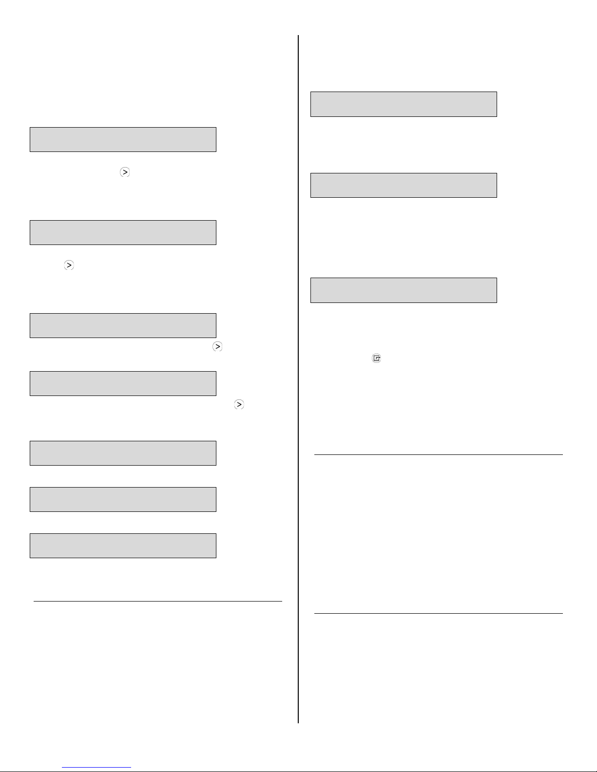
Normal Operation
The PHD 200 is preset to operate in Humidistat Mode at
50% RH level. To change this setting, see the instructions below.
Humidistat Mode
HUMIDISTAT MODE
ON/OFF >
In ON mode, unit will maintain the humidistat set point
(see below). Press MENU SELECTION to toggle between ON and OFF. NOTE: When in Humidistat mode,
the unit will display HUMIDISTAT on the top li ne during
normal operation rather than JOB HOURS.
HUMIDISTAT
SETPOINT 00% >
Sets humidity level when unit is in Humidistat M ode.
Press MENU SELECTION to change RH value. Each
press of the button increases the setting by 5% increments, cycling through 90%RH and starting again at
40%RH.
TEMP UNITS
F° >
Shows current temperature scale. Press MENU SELECTION to select Fahrenheit or Centigrade sc al e.
LANGUAGE
ENGLISH >
Shows current display panel language. Press MENU
SELECTION to select Spanish, German, F renc h or English.
To check, review the control panel. The control panel will
show one of the following:
Defrost in progress:
UNIT ON 00 HRS
DEFROST XX
Display mode when unit is in defrost mode. XX indicates
the minutes remaining on the defrost cycle.
Shutdown Sequence
WAIT FOR
DEFROST XX
Display mode when unit is in defrost and is powered
down by the user. Unit will complete the defrost cycle to
remove any built-up ice and then purge the pump. XX
indicates the minutes remaining on the defrost cy cle.
Normal Display:
UNIT ON 00 HRS
INLET XX° F
Wait until the control shows the normal display before
proceeding.
2. Gently rock the machine to ensure any water remaining on interior surfaces falls into the sump area.
3. Press the PURGE key. When the purge cycle is
complete, turn the unit off.
4. Remove the external drain hose and drain it carefully
before storing it.
5. Unplug power cord from power supply and from base
of the machine.
COIL TEMP
00°F
Displays the cold (evaporator) coil temperature.
SENSOR ID >
00000000
This function is not used on the PHD 200.
COMPRSSR CURRENT
0.0 A
Shows compressor current draw in amps.
AT THE END OF THE JOB
To reduce the possibility of drips when moving the unit,
follow these additional steps to ensure that all water is
removed from the unit.
NOTICE: To ensure the condensate tank empties completely while purging, make sure the unit is positioned
horizontally on a flat surface.
1. If the unit is in a defrost cycle, wait unt i l the unit has
returned to normal operating mode before proc eeding.
TRANSPORTATION AND STORAGE
NOTICE: Handle the unit carefully. Do not drop, throw,
or place the unit where it could fall. Rough treatment can
damage this equipment and may create a hazardous
condition or void warranty.
• Do not expose the control panel to moisture, snow
or rain.
• Protect from freezing.
• Store and transport securely to avoid any damaging
impact to internal parts.
• Secure during transport to prevent sliding and p os-
sible injury to vehicle occupants.
MAINTENANCE SCHEDULE
WARNING! ELECTRIC SHOCK HAZARD. Unplug unit
before cleaning or servicing.
WARNING: Risk of dust and contaminants exposure.
Use of respirator mask and gloves is recommended. I f
unit has been exposed to potentially dangerous cont a minants, clean thoroughly and sanitize before r euse.
07-01913A F515 2013-11 Warranty 07-01651 4 Dri-Eaz Products, Inc.
Page 5
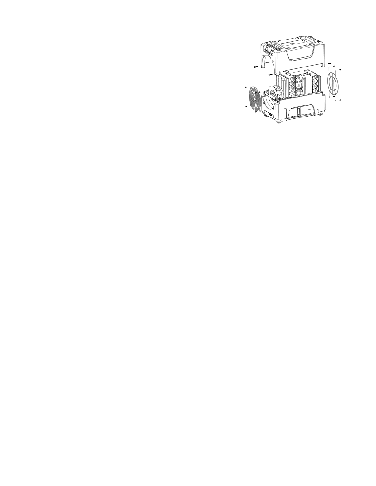
NOTICE: The unit is fitted with sensitive el ect ronic sen-
Remove the 4 screws
Fig. B: Disassembly for Cleaning
sors. Protect the sensors and their lead wires from damage and do not expose them to water or cleaning solution.
The following tools and supplies are needed to
complete the maintenance procedures described in
this manual:
Philips screwdriver
10 mm wrench
6 mm hex bit
¼ in. nut driver
Cleaning cloths
HEPA vacuum cleaner with soft brush nozzle and
crevice nozzle.
Recommended
Cordless drill, small knife, small-jaw pliers, coil cleaning solution, rotomolded housing cleaning soluti on.
Before each use
Inspect the electrical cord for damage. Look for fray-
ing, cuts, etc. Replace the cord if you find any dam age.
Inspect filter. The PHD 200 filter should be replaced
when the accumulation of dust is visible.
from housing and 2
top screws each from
inlet and outlet grills
and lift off cover.
Monthly
Inspect and clean coils and interior surfaces. In nor-
mal use, dust can accumulate and can restrict ai rf l ow,
reducing performance and causing the unit to overheat.
Clean when dust accumulation is visible. Remove grills
and cover as shown in Fig. B. Use a vacuum cleaner
with a brush tool and a soft cloth to remove any debris.
Take care not to damage any interior component s.
To maintain appearance, wipe interior and exterior surfaces with a damp cloth. For deep cleaning and a la sting, protective shine, use an automotive int erior cleaner.
As Needed
Clean pump check valve and basin. If the unit di splays
the message “ER9 PUMP BLOCKED CHECK PUMP &
HOSE”, the pump check valve and pump basin may
need to be cleaned. Remove grills and cover as sho wn
in Fig. B. Remove screws from pump base and lift out
pump. Wipe out pump basin with a damp cloth. Unth read
barbed fitting with check valve and rinse f itting and
check valve with clean water. Reinstall barbed fitting into
pump. Do not overtighten. Reinstall pump on base. Reinstall cover and grills.
Clean coils. With the cover removed, inspect both coils.
If excessive dust and debris is present, vacuum thoroughly and/or clean with coil cleaner.
07-01913A F515 2013-11 Warranty 07-01651 5 Dri-Eaz Products, Inc.
Page 6
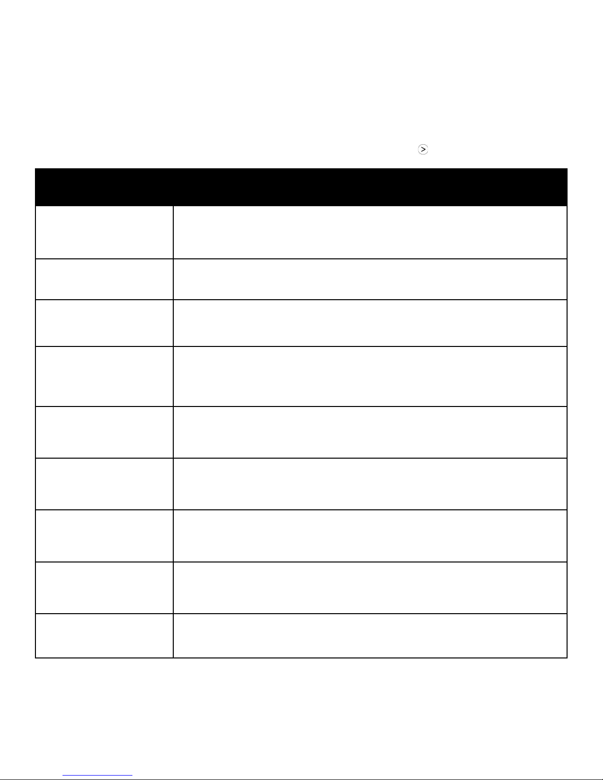
System messages
ER4 √ DEFROST SENSOR
CONNECT
The PHD 200 control system constantly monit ors internal operating conditions. If the system detects a problem, it will produce an error (“ER”) message. If the display shows an ER message, first unplug the unit and then plug it back in. This will
usually reset the electronics, and the unit wil l begi n operating normally. If the error message reappears, refer to the explanation and solution shown below. If this still doe s not fix the problem, contact your local authorized service center or call
the Dri-Eaz Service Department at 800-932-3030.
NOTE: The message “POWER FAILURE” i s n ot a system error. When this message is displayed, it indicates that
power to unit was interrupted and then restored. To clear the message, press the MENU SELECTION key.
CONTROL PANEL
MESSAGE
ER1 CONTACT SERVICE
CENTER
ER2 CONTACT SERVICE
CENTER
ER3 CONTACT SERVICE
CENTER
CONNECT
– alternate message –
ER4 √ OUTLET SENSOR
ER5 √ SENSOR
CONNECTION ON BD
EXPLANATION AND SOLUTION
Voltage error. Confirm that unit is connected to a suitable AC power supply and that the
circuit is not overloaded. If supply is correct, the electronic control panel may require
replacement. If error persists, co n tact service.
Control panel error. The electronic control panel may require replacement. If error persists, contact service .
Unit in defrost too long. Check defrost sensor cabl e for proper connection. If error persists, sensor assembly may require replacement. Contact service.
Sensor error. Check defrost sensor cable for proper connection. If error persists, sensor
assembly may require replacement. Contact se rv i ce.
Check inlet Temp/RH sensor for proper connect i on. If error persists, contact service.
ER6 CONTACT
SERVICE CENTER
ER7 INVALID
MODEL SETTING
ER8 BUTTON STUCK √
ALL BUTTONS
ER9 PUMP BLOCKED √
CHECK PUMP & HOSE
07-01913A F515 2013-11 Warranty 07-01651 6 Dri-Eaz Products, Inc.
High voltage error. The high voltage board may req ui re replacement. If error persists,
contact service.
Control board DIP switch settings or firmware version may be incorrect. If error persists,
contact service. Service may ask you to verify DIP switch settings.
Press each membrane key and check for proper operation. If a key doesn’t function, or
if the error persists, the membrane overlay m ay require replacement. Contact service.
Check for obstructions in drain hose. If clogged, remove hose from unit and blow hose
out with compressed air. Inspect and clean the pump check valve and pump basin. See
“Clean pump check valve and basin” p. 5.
Page 7
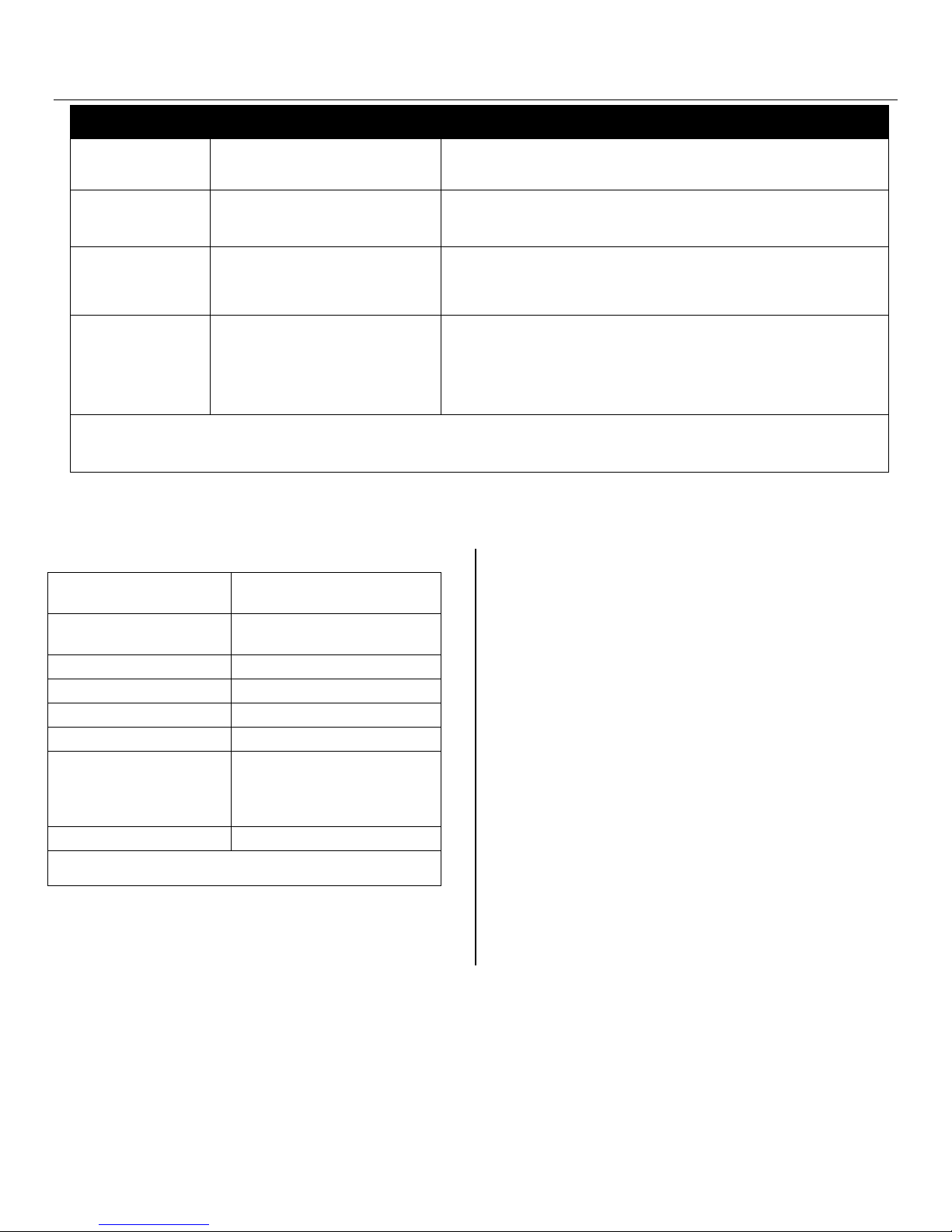
TROUBLESHOOTING
Switch unit on.
base of unit.
may be approximate.
FAULT CAUSE SOLUTION
Water drips out
when moving unit
Unit does not
operate
Unit operating,
but room not dry
Unit was unplugged before
purging was complete.
Unit not switched on.
No power to machine.
Not enough time to dry.
Poor air movement in room.
Excessive moist air infiltration.
Room air is dry.
Unit collects too
little water
Room temperature is too low.
Filter is clogged.
Coils are clogged.
If the problem you are experiencing is not list ed here, call your local distributor or contact
our Service Department toll-free at 800-932-3030 for further assistance.
SPECIFICATIONS
Name
Dimensions (W × H × D)
Weight (w/ cord & hose) 65 lbs. | 29.5 kg
Amps 6.2 amps at 80°F/60% RH
Power 115V / 60Hz
Air movement 121–180 CFM | 2.4–5.4 CMM
Water removal
Operating temperature range 33–100°F |1–38°C
Specifications are subject to change without notice. Some values
PHD 200 Dehumidifier
Model F515
12.5 × 17.6 × 21.5 in.
31.8 × 44.7 × 130.8 cm
80 pts/day | 38 L/day
at 80°F/60% RH (AHAM)
134 pts/day | 63 L/day
at 90°F/90% RH
Purge unit before moving. See “At the End of the Job,” p. 4.
Plug in unit; check power cord connection at wall out l et and at
Allow more time for drying.
Increase air movement with air movers.
Seal off area to reduce infiltration.
Confirm humidity level with hygrometer.
Increase room temperature.
Check filter. Clean or replace as necessary.
Check coils. Clean as necessary.
PARTS INCLUDED
20 ft. (6 m) of drain hose with quick-connect fitting.
6 ft. (1.8 m) detachable power cord.
1 disposable air filter
Optional
Joist Mounting Kit (Order F525)
ADDITIONAL PRODUCT INFORMA TI ON and current
documentation is available at http://Revo.DriEaz.com.
FOR PARTS AND SERVICE CALL YOUR LOCAL
DISTRIBUTOR or Dri-Eaz at 800-932-3030.
www.dri-eaz.com
Visit warranty.DriEaz.com and register your purchase to
ensure you receive any important product rel eases.
07-01913A F515 2013-11 Warranty 07-01651 7 Dri-Eaz Products, Inc.
 Loading...