

Page 1

Owner’s Manual –
Dragon K85 Mobile
Furnace
115-volt model
DRI-EAZ PRODUCTS, INC.
15180 Josh Wilson Road, Burlington, WA USA 98233
Fax: (360) 757-7950 Phone: (360) 757-7776
www.dri-eaz.com
The Dragon K85 Mobile Furnace is a diesel fuel- and
electric-powered indirect fired heater. It provides heated
air without adding moisture for a variety of applications,
including water damage restoration, structural drying,
construction, and temporary event shelters.
Safety Information
Read this Owner's Manual carefully to learn how to
properly operate and service your Dragon K85 Mobile
Furnace. This manual should be considered a
permanent part of the machine and should remain
with the Dragon if you sell it.
Failure to comply with the instructions and precautions
provided in this Owner’s Manual can result in death,
serious bodily injury, and/or property loss or damage
from hazards of fire, explosion, burn, asphyxiation,
carbon monoxide poisoning, and/or electrical shock.
Electrical Connections
The Dragon K85 Mobile Furnace is designed to operate
on a 115V/60 Hz electrical connection. Make sure that
the electrical outlet is grounded with three prongs. When
using with an extension cord, use only a grounded cord
intended for outdoor use and rated to deliver enough
power to the Dragon (4.4 amps@115V
or 506W).
Failure to use diesel fuel could cause injury and
permanent damage to the unit. It may also void the
Dri-Eaz warranty.
Altitude Adjustment
The Dragon is factory-set for use at elevations up to
2000 feet. For use above 2000 feet, the unit must be
adjusted to avoid excessive soot build-up and possible
flue fire. Failure to adjust for high-altitude use could
cause injury, permanent damage to the unit and
secondary damage when ducting into a structure.
It may also void the Dri-Eaz warranty. Have a qualified
HVAC technician adjust the unit for use in your area.
Black or gray/white smoke coming from the flue
indicates an improper air to fuel ratio. Call an authorized
service center or HVAC specialist for assistance.
For questions call: 1-888-867-3235.
OVERVIEW
Introduction
The Dragon K85 Mobile Furnace is an indirect fired
heater. It supplies heated air to an area without adding
any moisture or fumes through the heating process. The
Dragon is able to do this by using a heat exchanger so
that the process air never comes into direct contact with
the flame in the combustion chamber.
The Dragon operates from outside the structure. It draws
in the ambient outdoor air and increases its temperature
by 81°F. An electric fan directs this heated air into the
structure through ducting. The remote thermostat
automatically cycles the Dragon on and off to maintain a
preset temperature in the affected area.
The clean, dry heat from the Dragon helps reduce drying
times while maintaining stable and comfortable
temperatures. The Dragon is ideal for any number of
applications, including:
• water damage restoration
• new construction drying
• unheated jobsites
• temporary event shelters
• any situation calling for clean, dry heat
Fuel Type
The Dragon K85 Mobile Furnace is designed to operate
on diesel #2 fuel oil only. The Dragon can operate for a
minimum of 8 hours using the internal
gallons (35 L). Do not run the Dragon out of fuel, as it
may be difficult to restart. For longer unattended use, it
is recommended that you purchase a larger, DOTapproved external
siphon.
If external tank is used, cover opening to prevent
contaminants from entering tank. Place tank on flat,
stable surface to prevent tipping or spilling.
07-00407 E 08/2006 Copyright 2006 Dri-Eaz Products, Inc.
fuel tank to use with the external fuel
tank that holds 9.3
Principles of Use
For applications like water damage restoration and new
construction drying, the Dragon can increase drying
efficiency.
Areas of a structure that can benefit from the addition of
heat for drying include: crawlspaces, basements, or
parts of a building where heat is not available.
Cold air actually impairs the evaporation of moisture
from materials. Warm air from the Dragon helps
airmovers and dehumidifiers evaporate more moisture
from materials and remove it from the structure. For
instance, raising the temperature of an area with the
1
Page 2

Dragon by just 10°F (from 60°F to 70°F) can increase
the evaporative potential of your existing drying system
up to 45 percent.
The specific target drying temperature will vary
according to the conditions of each drying job.
Determining, creating, and maintaining the optimum
drying conditions on a job—including temperature and
relative humidity—is your responsibility.
For best results when using the Dragon for drying,
you should understand the basic principles of
psychrometry—the science of drying. You should also
know how to use moisture detection instruments to track
the moisture content of a structure throughout the entire
drying process. You can learn these skills and more in
an IICRC-certified Applied Structural Drying (ASD)
course. To learn more about ASD courses, contact the
Dri-Eaz Education Department at 1-800-575-5152.
With this in mind, there are some general principles to
keep in mind when using the Dragon. You should try to
stabilize the temperature of the affected area near the
ideal operating temperature of your drying equipment.
Most dehumidifiers perform at their best between 70°F to
90°F. The added heat from the Dragon will increase the
rate of evaporation by decreasing the relative humidity of
the affected area. Be certain that your combination of
airmovers and dehumidifiers is powerful enough to keep
the relative humidity well below 60%RH to avoid
secondary damage to the structure and contents.
Parts Identification
Accessories Included
The Dragon K85 Mobile Furnace includes the following
parts and accessories:
Dragon K85 Mobile Furnace
1
Flue with cap
1
Remote thermostat
1
External fuel siphon
1
30-ft ducting (8-in diameter)*
2
Duct clamps
2
2-ft heat shields (10-in diameter)
2
*Replacement ducting can be obtained
from Grainger (Part #3XK06). For more
information, go to www.grainger.com
Rear Handle
A
Air Intake Grill
B
Flue
C
Ducting
D
Fuel line guard plate
E
Internal tank fuel lines
F
External fuel siphon holder
G
Wheels
H
Duct rings
I
Front handle/cord wrap
J
Flame Control Reset Button
K
Fuel pump/blower assembly housing
L
Power cord
M
FAN switch
N
HEAT switch
O
Thermostat jack
P
Temperature-Limiter Reset Button
Q
Internal fuel tank fill neck
R
Internal fuel tank drain plug
S
Air Intake vents
T
07-00407 E 08/2006 Copyright 2006 Dri-Eaz Products, Inc.
2
Page 3

OPERATING THE DRAGON
Breathing Hazard
Fuel exhaust contains deadly carbon monoxide gas.
Operate Dragon only outdoors in open area. NEVER
operate indoors or in enclosed spaces.
Electric Shock Hazard
Unit must be grounded. Use only with 3-hole grounded
outlet.
Never modify plug or use an adaptor. If an extension
cord is needed, it must have a three-prong grounding
plug, be rated for outdoor use and be rated for at least
506 watts or 4.4 amps @ 115 volts.
Never operate the Dragon in pooled or standing water. If
electrical components become wet, allow to dry before
using.
snow, etc. Blocking the air intake will cause the unit to
burn inefficiently resulting in sooty exhaust and potential
damage to the unit and the structure being heated.
Air Intake vents shown from underneath unit.
Fire and Explosion Hazard
Burner produces sparks and flame and unit becomes hot
during use.
Keep away from flammable vapors, such as those from
gasoline, paint thinner or solvents.
Keep away from combustible dusts, such as coal dust or
sawdust.
Keep unit at least ten feet away from any combustible
material.
Keep children and pets away.
Diesel fuel is flammable and can be explosive.
Do not smoke while operating, servicing, or refueling
the Dragon.
Before refueling, shut off unit, allow to cool and then
unplug.
Hot surfaces can ignite fuel vapors.
Setting up the Dragon
Choosing a location
Use the Dragon outdoors only. Place the unit on a level,
stable surface. Choose an inconspicuous location away
from high-traffic areas for children and/or pets. Ensure
there is no obstruction in the air intake during the use of
the Dragon.
NOTICE: Keep air intake vents under unit clean and
clear of any obstruction. Avoid setting up unit where the
intake could be blocked or restricted i.e. tall grass, deep
07-00407 E 08/2006 Copyright 2006 Dri-Eaz Products, Inc.
Connecting the internal tank fuel lines
To connect the fuel lines, simply push the male and
female adapters together until the lock rings snap
into place. Note that the adapters are arranged so
that you will always connect the lines properly. You
must always connect both
fuel lines.
Connect the internal tank fuel lines
The Dragon is shipped with the fuel lines disconnected.
Before operating, make sure the fuel lines from the
internal tank are properly connected.
You may also operate the Dragon with an external fuel
tank (not included). See the section "Connecting an
external fuel tank" for more information.
Fill the internal fuel tank
The Dragon is shipped with an empty fuel tank. Before
operating, fill the internal tank with diesel #2 fuel oil
The internal tank has a 9.3-gallon capacity. Do not
overfill.
3
only.
Page 4

Attaching the flue to the Dragon
The Dragon is designed to operate with the flue attached
to the top of the unit. Always operate the Dragon with the
flue attached. In addition to preventing any water or
debris from falling into the heat exchanger, the flue
creates a slight draft on the Dragon exhaust that assists
in preventing thermal overload.
1. To attach the flue, slide it over the pipe on top of the
heat exchanger.
3. Drive a sheet metal screw (#8x1) through each hole
to secure the flue to the Dragon.
Attach the flue to the Dragon
2. Drill two 1/8-inch holes through the bottom of the
flue into the heat exchanger pipe. The holes should
be approximately 90 degrees apart.
Secure the flue to the Dragon with sheet metal screws
Attaching ducting to the Dragon
The Dragon delivers clean heat to a structure through
two 30-foot lengths of 8-inch diameter aluminum ducting.
You must attach both lengths of ducting to the Dragon
for operation.
1. Extend a 1-foot section of ducting and slide a hose
clamp over the end. Slip the ducting over one of the
Dragon outlet duct rings. Secure the ducting firmly to
the duct ring with the hose clamp. Make sure the
clamp is tight enough to hold the ducting in place
when you extend it to the structure.
Drill two 1/8-inch holes in the flue
07-00407 E 08/2006 Copyright 2006 Dri-Eaz Products, Inc.
Clamp the ducting securely to the duct ring
4
Page 5

2. Slide one of the heat shields over the ducting until it
rests against the Dragon housing. This will provide
extra protection against burns from accidental
contact with hot surfaces near the duct rings.
6. Repeat steps 1 through 4 for the second length of
aluminum ducting. Always connect both lengths of
ducting from the Dragon to the affected area.
Connecting the remote thermostat
The thermostat monitors the temperature in the affected
area. It turns the Dragon on and off to maintain a preset
temperature in the affected area.
Always operate the Dragon with the remote thermostat
connected. The HEAT switch will not function and the
Dragon will not heat the air if the thermostat is not
connected.
Slide the heat shields in place
3. Grasp the free end of the ducting and pull until it
reaches the structure. Take care not to damage the
aluminum ducting, as this could restrict airflow
during operation and cause the unit to shut off from
thermal overload.
4. Repeat steps 1 through 3 for the other length of
ducting. Always connect both lengths of ducting from
the Dragon to the affected area.
Securing ducting to the structure
In most drying situations you will need to attach the end
of the ducting to an opening in the structure such as a
basement window or crawlspace vent hole. Since each
structure is unique, you will usually need to build an
adapter to fit the specific opening.
To build two adapters, you will need:
2 Plywood sheets
2 Duct adapters, 8-inch diameter
2 Hose clamps
1 Jigsaw
1. Cut a sheet of plywood to fit over the opening in the
structure.
2. Use a jigsaw or similar tool to cut an 8-inch diameter
hole in the center of the plywood.
3. Fit an 8-inch diameter duct adapter (available at
most hardware stores) into the hole in the plywood.
Secure the duct adapter to the plywood.
4. Slip a hose clamp (not included) over the free end of
one of the 30-foot lengths of 8-inch diameter
aluminum ducting. Slide the ducting over the adapter
and secure firmly with the hose clamp.
5. Secure the plywood to the structure.
The remote thermostat sensor cable, control box, cable, and jack
1. Run the thermostat’s 8-foot sensor cable into the
affected area. If necessary, drill a small hole in the
plywood adapter.
2. Position the tip of the sensor cable as far away as
possible from the Dragon process air—at least six
feet for best results.
Note: Only the tip of the sensor cable will read
temperature.
3. Place the thermostat control box where it will be
easy to monitor temperature setting. The control box
is weatherproof and may be left outside.
07-00407 E 08/2006 Copyright 2006 Dri-Eaz Products, Inc.
5
Page 6

4. Plug the thermostat into the jack on the Dragon. The
jack is located next to the HEAT and FAN switches.
Plug the thermostat into the jack on the Dragon
Note: The HEAT switch will not function and the
Dragon will not heat the air unless the thermostat is
plugged into the jack.
For more information about operating the remote
thermostat, see the section "Programming the
thermostat."
Establishing negative air pressure
Always create a negative air pressure in the affected
area when using the Dragon. An area has negative air
pressure when the air pressure inside is lower than
outside. This helps prevent odors and contaminants from
spreading to unaffected areas through cracks, crevices,
and openings in the structure walls.
On average, the Dragon will force in about 800 CFM. As
long as you remove more than 800 CFM through an
exhaust opening, more air will flow out
area than will flow in from the Dragon. This differential
creates the negative air pressure in the affected area—a
slight vacuum effect—so that any contaminants and
odors are exhausted harmlessly outdoors instead of
being forced into other areas of the structure.
1. First close or block any large openings between the
affected area and other parts of the structure.
2. Select an opening between the affected area and
the outdoors to use as an exhaust, preferably on a
side opposite the Dragon process air. A window or
crawlspace vent hole will do.
3. Place a TurboDryer, Vortex Axial Fan, or other
airmover so that it forces air out
to the outdoors
airmover should remove at least 800 CFM from the
affected area.
through the selected opening. The
of the affected
of the affected area
Starting the Dragon
Inspecting before operation
Warning! Before starting the Dragon:
Check for any fuel leaks around the fuel tank or fuel
lines.
Check for nearby hazards like combustible materials
or flammable vapor sources.
Check the power cord for damage.
Correct these and any other safety hazards before
starting the Dragon.
Starting the Dragon
1. Check the fuel tank. If needed, add #2 diesel fuel to
the fuel tank. Do not overfill. WARNING! Turn off
power and allow unit to cool before refueling.
2. With the ducting secured, the thermostat in place,
and negative air pressure established, plug the
Dragon’s power cord into a nearby outlet.
3. Turn the HEAT switch to on. This provides power to
the thermostat. The thermostat will only function
when the HEAT switch is on.
4. While the Dragon’s heat exchanger is warming up,
set the desired temperature on the thermostat
control box. See the next section, "Programming the
thermostat," for more information.
5. Monitor the settings on the Dragon and conditions in
the structure at least twice daily during operation.
Programming the thermostat
The remote thermostat controls the operation of the
Dragon. Based on the settings you program, the Dragon
will cycle on and off to maintain a predetermined
temperature in the affected area. It can be programmed
in either degrees Fahrenheit or Celsius.
1. When the Dragon is plugged in and the HEAT
switch is first turned on, the thermostat will display
the ambient temperature.
07-00407 E 08/2006 Copyright 2006 Dri-Eaz Products, Inc.
Before programming, the thermostat shows the current ambient temperature
6
Page 7
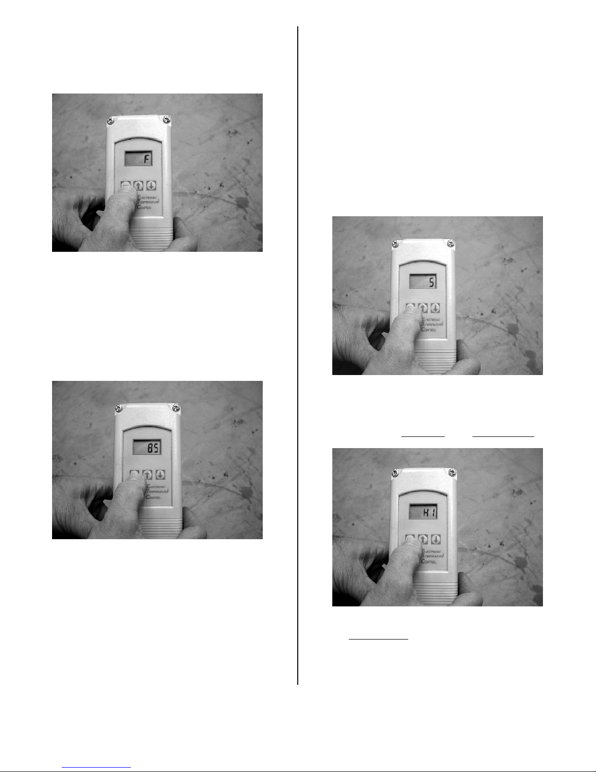
2. Press the SET key once to access the
Fahrenheit/Celsius mode. The display will show the
current status, either F for Fahrenheit or C for
Celsius. To switch between the two, press either
arrow key. Choose either F or C.
3. Press the SET key again to access the differential.
The display will blink "DIF 1" and show the current
differential. The differential is the number of degrees
the temperature will drop below the setpoint before
the Dragon begins a heating cycle. In other words,
the differential determines the minimum temperature
of the affected area.
For example, with a setpoint of 85°F and a
differential of 5, the Dragon will begin a heating
cycle when the temperature of the affected area
drops below 80°F.
Press the up or down arrow keys to select a
differential. You can select a differential from 1°F
to 30°F.
Choose either Fahrenheit (F) or Celsius (C) mode
2. Press the SET key again to access the setpoint.
The display will blink "S1" and show the current
setpoint in degrees. The setpoint is the maximum
temperature you wish to maintain in the affected
area.
For example, with a setpoint of 85°F, the Dragon will
stop heating when the temperature exceeds 85°F.
Use the arrows to choose a setpoint.
Use the arrows to select a differential
4. Press the SET key again to access the heating or
cooling mode. The display will show the current
mode, either C1 for cooling or H1 for heating. Using
the arrow keys, select H1
for the heating mode.
Use the arrows to choose a setpoint
07-00407 E 08/2006 Copyright 2006 Dri-Eaz Products, Inc.
Important! Make sure the thermostat is set to H1 for
the heating mode
. The Dragon will not function
properly with the thermostat in cooling mode.
5. Press the SET key once more to complete the
programming of the thermostat.
7
Page 8
Shutting the Dragon Off
1. Turn the HEAT switch to “Off” but leave the unit
plugged in. NOTICE: Do not turn the Dragon off by
simply unplugging the unit, as this could cause
thermal overload. You must allow time for the fan to
cool the heat exchanger.
2. Leave the unit plugged in for at least 10 minutes
while the fan cools the heat exchanger. The fan will
turn off and on during the cooling cycle.
3. After a minimum 10-minute cooling period, you may
unplug the unit.
Special Instructions
Preventing thermal overload
If the temperature of the heat exchanger exceeds 212°F
(100°C), the Dragon will automatically shut down due to
thermal overload and must be reset before it will start
again. The most common cause of thermal overload is
restricted airflow. To help prevent thermal overload, you
should:
• Make ducting runs as straight as possible
• Keep the ducting free of debris and unobstructed
• Keep the air intake grill unobstructed
Restarting after thermal overload
If the Dragon shuts off due to thermal overload, follow
these instructions for restarting.
1. Wait 10 minutes to let the Dragon cool down.
2. Make certain that ducting runs are straight and
unobstructed. Make certain the air intake is
unobstructed.
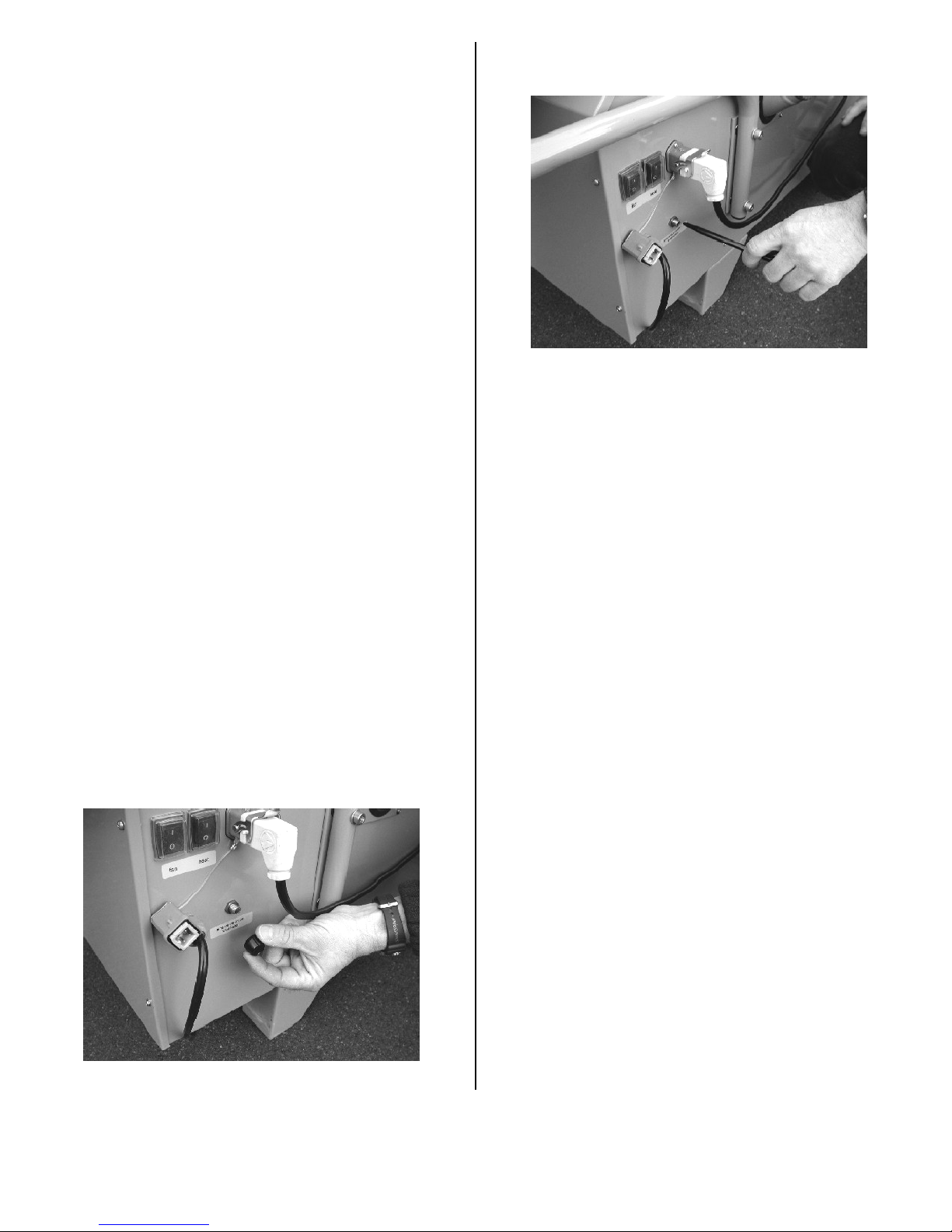
3. Unscrew the plastic cover for the TemperatureLimiter Reset Button located near the HEAT and
FAN switches.
4. Using a pen or a pencil, depress the TemperatureLimiter Reset Button.
Use a pen or pencil to depress the Temperature-Limiter Reset Button
4. Replace the plastic cover on the TemperatureLimiter Reset Button.
5. Make certain the HEAT switch is turned on.
If the heater continues to shut off due to thermal
overload, contact the Dri-Eaz Service Department at
1-888-867-3235.
Restarting after running out of fuel
If the Dragon runs out of fuel, it will automatically shut
off.
NOTICE: Check internal tank fuel level at least every
8 hours to avoid running out of fuel, as the unit may
require servicing to be restarted.
Follow these instructions for restarting:
1. Turn the HEAT switch off and unplug the Dragon.
WARNING! Allow the Dragon to cool for at least 10
minutes.
2. Refill the fuel tank with diesel #2 fuel oil only. The
internal tank has a 9.3-gallon capacity. Do not
overfill. Turn off power and allow unit to cool before
refueling.
3. Plug the Dragon back in to a grounded outlet using
an appropriately rated extension cord.
4. Turn the HEAT switch to on.
Remove the plastic cover for the Temperature-Limiter Reset Button
07-00407 E 08/2006 Copyright 2006 Dri-Eaz Products, Inc.
8
Page 9
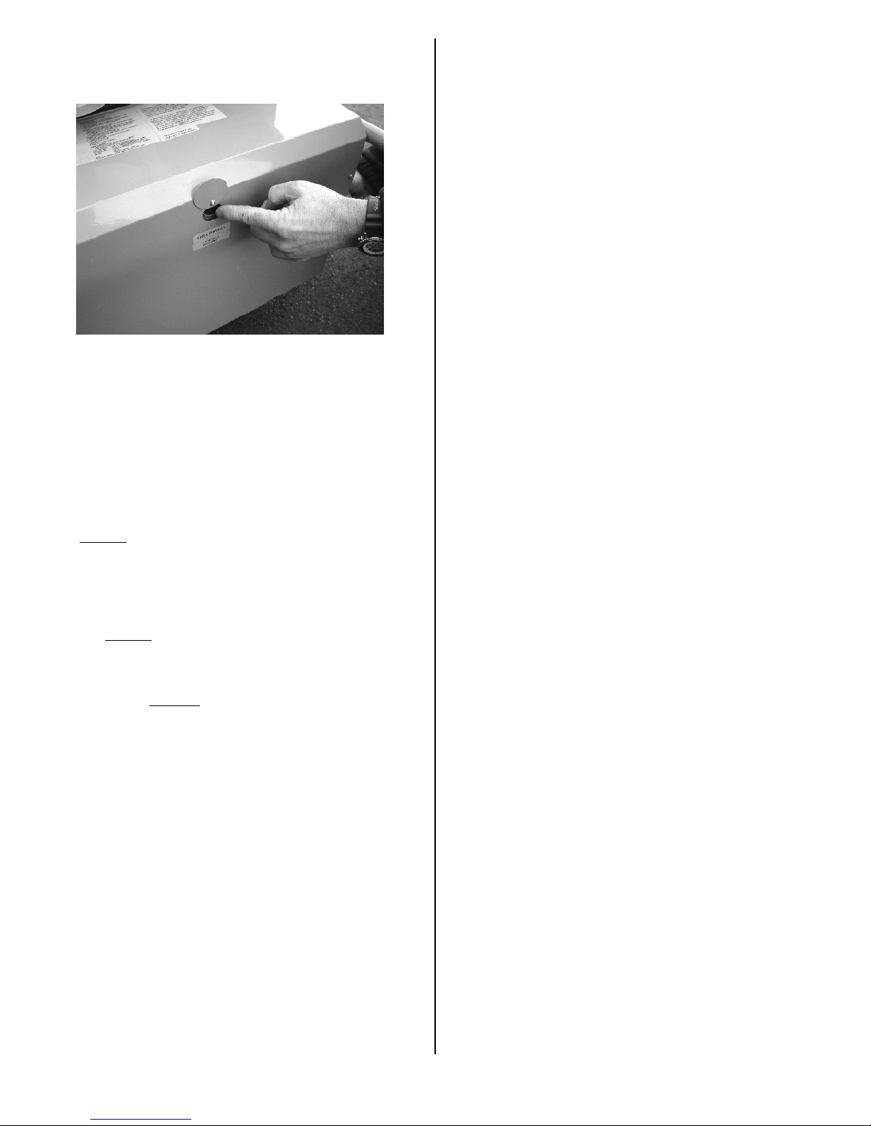
5. Press the Flame Control Reset Button once. To
access the button, swivel the metal cover on the fuel
pump/blower assembly housing.
Press the Flame Control Reset Button
6. The Dragon will restart after priming the fuel pump.
If the Dragon does not restart immediately, wait one
minute and press the Flame Control Reset Button
again. Repeat until the Dragon starts. If the unit will
not restart, contact Dri-Eaz Service at 888-867-
3235.
Using an external fuel tank
The internal fuel tank of the Dragon K85 Mobile Furnace
has a capacity of 9.3 gallons (35 L). Depending on the
specific conditions and thermostat settings, the Dragon
can operate anywhere from a minimum of 8 hours (firing
continuously at 0.69 gal/hr) up to more than 24 hours
(firing intermittently to maintain a constant temperature)
on a full internal
If you will be operating the unit unattended for more than
8 hours, we recommend that you purchase a larger
DOT-approved external
fuel siphon on the Dragon. This will allow you to operate
the Dragon for longer periods between refueling. Even
though you may not need to refuel with an external tank,
you should continue to physically check the Dragon at
least once a day during operation.
WARNING! Diesel fuel is flammable and potentially
explosive. Place external tank on flat, stable surface to
prevent spills.
NOTICE: Always use a clean fuel tank and fuel source
to prevent fuel problems. Cover the opening to prevent
moisture or contaminants from getting into fuel.
tank of fuel.
fuel tank to use with the external
Connecting an external fuel tank
WARNING! Diesel fuel is flammable and potentially
explosive. Always turn off and unplug the Dragon before
switching between internal and external tanks. Do not
smoke while connecting fuel tanks. Keep away from
open flame.
1. Disconnect the two fuel lines coming from the
internal fuel tank. To do this, slide the lock rings
back and pull the adapters apart.
2. To prevent fuel leakage or damage to the adapters,
connect the fuel lines together while not in use. Wipe
any excess fuel oil from the adapters.
3. Connect the fuel lines from the external fuel siphon
to the adapters on the Dragon housing. To do this,
push the male and female adapters together until
the lock rings snap into place. NOTICE: Be sure the
lock rings snap securely to avoid diesel fuel leakage.
4. Insert the siphon into the external fuel tank. Feed
the fuel lines through the plastic cover until the
siphon rests on the bottom of the tank.
5. Operate the Dragon as instructed elsewhere in this
manual.
Reconnecting the internal fuel tank
WARNING! Diesel fuel is flammable and potentially
explosive. NOTICE: Always turn off and unplug the
Dragon before switching between internal and external
tanks. Do not smoke while connecting fuel tanks. Keep
away from open flame.
1. Remove the external fuel siphon from the external
fuel tank. Wipe the siphon and fuel lines clean of
excess fuel oil.
2. Disconnect the fuel lines from the external tank. To
do this, slide the lock rings back on the female
adapters and pull the adapters apart.
3. To prevent fuel leakage or damage to the external
fuel line adapters, connect the lines together while
not in use. Wipe away any excess fuel oil.
4. Connect the fuel lines from the internal fuel tank to
the adapters on the Dragon housing. To do this,
push the male and female adapters together until
the lock rings snap into place. Note that the male
and female adapters are arranged so that you will
always connect the lines properly.
Draining the internal fuel tank
You may occasionally need to drain the internal fuel tank
for shipping or storage. The Dragon is equipped with a
fuel tank drain plug on the bottom of the unit near the
wheel axle.
07-00407 E 08/2006 Copyright 2006 Dri-Eaz Products, Inc.
9
Page 10
You will need:
• Phillips screwdriver
• Clean shop rags
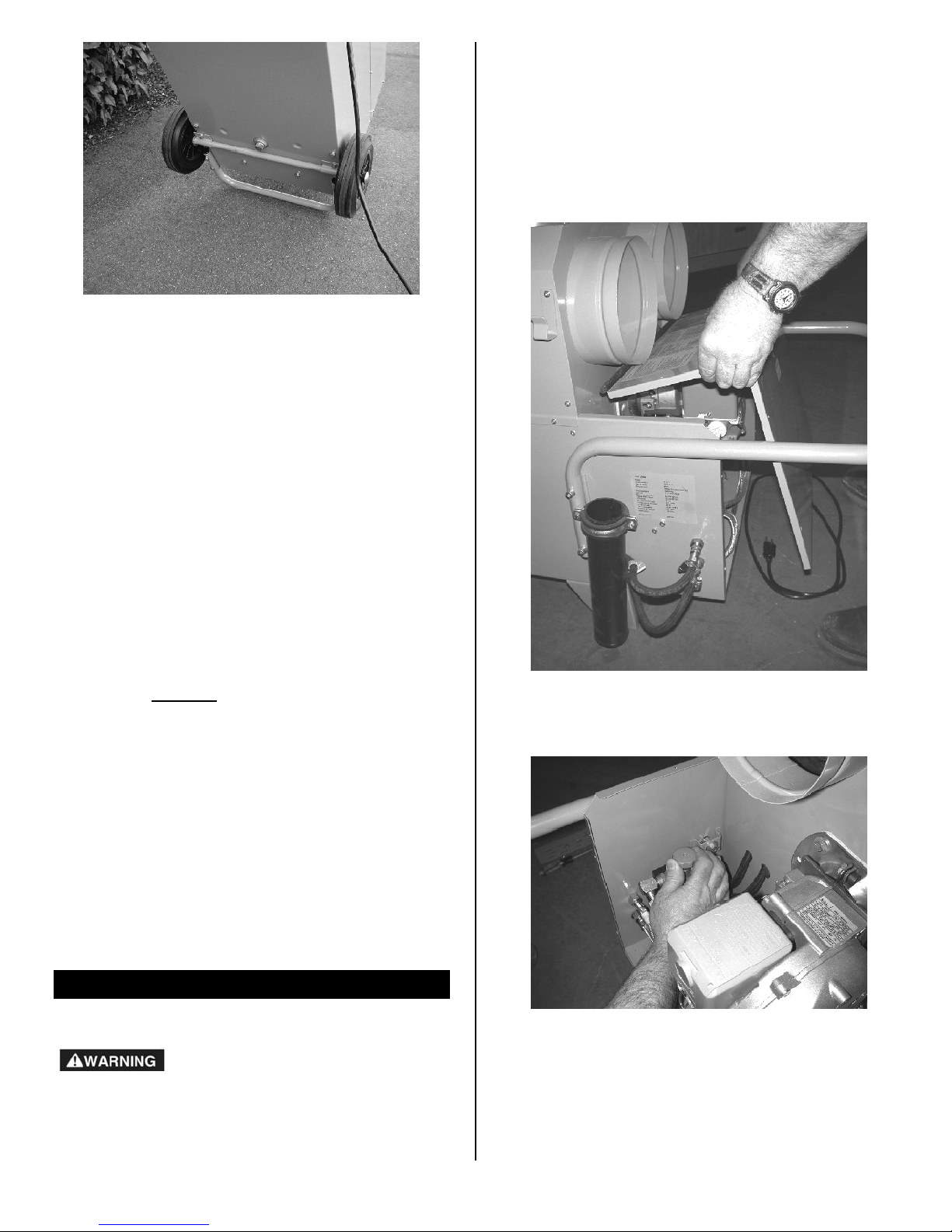
1. Remove the housing cover for the fuel pump/blower
assembly and the fuel line guard plate. To do this,
remove the six Phillips screws that secure the
housing cover and guard plate.
The internal fuel tank drain plug
WARNING! Diesel fuel is flammable and potentially
explosive. Always turn off and unplug the Dragon before
draining the internal fuel tank. Do not smoke while
draining fuel. Keep away from open flame.
1. Place an appropriate container beneath the drain
plug to catch any remaining fuel oil.
2. Remove the drain plug with a wrench.
3. Allow the internal fuel tank to drain completely.
4. Screw the drain plug back into the Dragon. Tighten
with a wrench.
5. Dispose of excess fuel oil in accordance with local
regulations.
Using the Dragon as a ventilator
The Dragon may also be used purely as a ventilator to
deliver clean, unheated air to an affected area.
NOTICE: If you are ventilating spaces adjacent to
living areas, you must still create a negative pressure in
the affected area. This will help prevent contaminants
from being forced into clean areas. See the section
"Establishing negative air pressure" for more
information.
1. Set up the Dragon as directed in the section "Setting
up the Dragon." However, you do not need to add fuel,
attach the flue, or connect the remote thermostat. As a
ventilator the Dragon will operate on electricity alone.
2. Turn the FAN switch to “On.”
Remove the fuel pump/blower assembly housing and guard plate
2. Close the fuel line shut-off valve by turning the red
knob clockwise.
MAINTENANCE
Replacing the fuel intake filter
The fuel intake filter should be replaced at least once
every year. Depending on the quality of fuel oil and the
frequency of use, the fuel intake filter may need to be
replaced more frequently.
07-00407 E 08/2006 Copyright 2006 Dri-Eaz Products, Inc.
Close the fuel line shut-off valve
10
Page 11
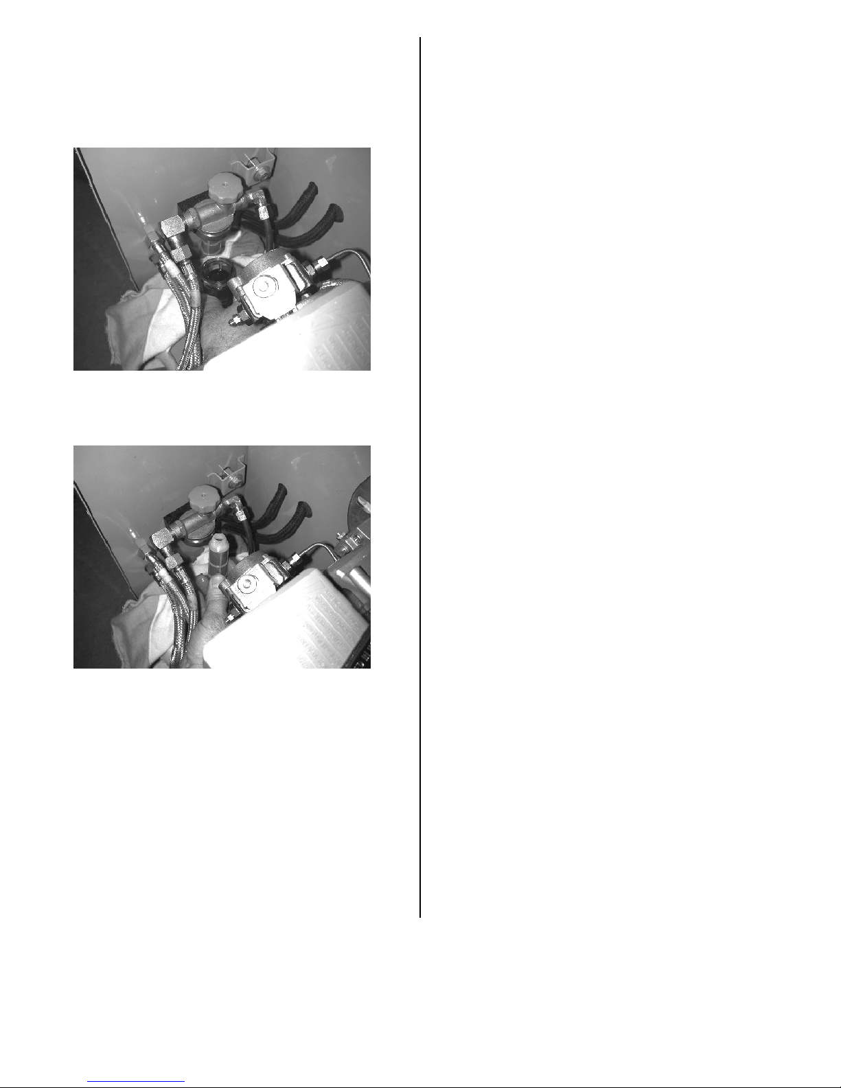
3. Place a shop rag beneath the filter reservoir to catch
any spilled fuel, and then unscrew the reservoir by
hand. Dispose of the fuel oil in the reservoir in
accordance with local regulations. Wipe down the
inside of the empty reservoir with a clean rag to
remove any debris. Set the empty reservoir aside.
Unscrew the filter reservoir by hand
4. Unscrew the fuel intake filter by hand. Dispose of the
used filter in accordance with local regulations.
Unscrew the fuel intake filter by hand
5. Insert a new fuel intake filter and gently tighten by
hand. Do not reuse the old filter. Do not overtighten.
6. Replace the reservoir and gently tighten by hand. Do
not overtighten. Wipe up any spilled fuel oil.
7. Reopen the fuel line shut-off valve by turning the red
knob counter-clockwise.
Note: You should also inspect the fuel pump screen
whenever you replace the fuel intake filter. For more
information, see the section titled, "Inspecting the fuel
pump screen."
8. With the housing cover still off, check for leaks
around the fuel intake filter reservoir during operation.
To do this, set the Dragon up outside and allow to run
in HEAT mode for several minutes. If the reservoir
does not leak, proceed to step 9.
If the reservoir leaks, turn off and unplug unit before
attempting to tighten or reseal the fuel intake filter and
reservoir. If the fuel intake filter and reservoir will not
stop leaking, have the unit inspected at a qualified
service center.
9. Reattach the fuel pump/blower assembly housing
cover and guard plate.
Inspecting the fuel pump screen
You should inspect and clean the fuel pump screen at
least once a year or whenever you replace the fuel
intake filter. Depending on the quality of fuel oil and the
frequency of use, the screen may need to be cleaned
more often. If the screen is damaged, it must be
replaced. Barring damage, the screen may be cleaned
and reused indefinitely.
You will need:
• Phillips screwdriver
• 4-mm Allen wrench
• 1/4 cup of clean fuel oil
• Small nylon-bristled brush
• Shop rags
• New fuel pump screen (if necessary)
1. Remove the housing cover for the fuel pump/blower
assembly and the guard plate for the external fuel line
connections. To do this, remove the six Phillips
screws that secure the housing cover and guard
plate.
2. Close the fuel line shut-off valve by turning the red
knob clockwise.
07-00407 E 08/2006 Copyright 2006 Dri-Eaz Products, Inc.
11
Page 12
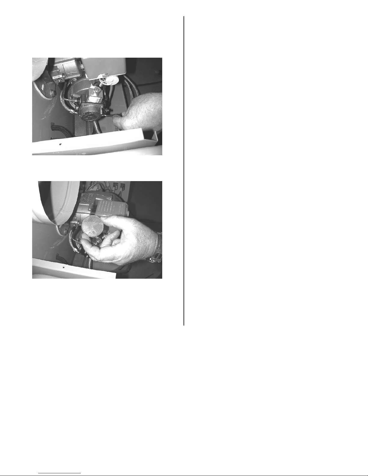
3. Place a shop rag beneath the fuel pump to catch any
spilled fuel oil, and then remove the fuel pump cover.
To do this, use a 4-mm Allen wrench to remove the
four bolts that secure the cover to the fuel
pump/blower assembly.
Remove the fuel pump cover
4. Remove the fuel pump screen.
6. Rinse the screen in the 1/4 cup of clean fuel oil. If
necessary, gently scrub the screen with the nylonbristled brush (a toothbrush works well) to remove
any debris or buildup.
7. Replace the screen and fuel pump cover. Tighten the
bolts snugly. Wipe up any spilled fuel oil from the
housing or fuel pump.
8. Reopen the fuel line shut-off valve by turning the red
knob counter-clockwise.
9. Before replacing the housing cover, check for leaks
around the pump cover during operation. To do this,
set up the Dragon outside and allow to run in HEAT
mode for several minutes. If the fuel pump cover does
not leak, proceed to step 9.
If the fuel pump cover leaks, turn off and unplug unit
before attempting to tighten or reseal the cover. If the
cover will not stop leaking, have the unit inspected at
a qualified service center.
10. Reattach the housing cover and guard plate.
Remove the fuel pump screen
5. Inspect the screen for damage. If the screen is not
damaged, proceed to step 6. If the screen is bent,
torn, cracked, or damaged in any way, discard it and
skip to step 7 with a new fuel pump screen.
Cleaning the Dragon
The heat exchanger and combustion chamber should be
cleaned at least once a year to remove soot buildup.
The cleaning should be performed by a qualified HVAC
technician at a local service center. Contact your local
distributor or the Dri-Eaz Service Department at 1-888867-3235 for the location of a service center near you.
To clean the Dragon housing, use a cleaner with a
degreasing agent similar to Simple Green
®
.
07-00407 E 08/2006 Copyright 2006 Dri-Eaz Products, Inc.
12
Page 13

SPECIFICATIONS
MODEL Dragon K85 Mobile Furnace
Model Number F260
Dimensions – HxWxD 28" x 23" x 40" (71 x 58 x 102 cm)
Use Weight 188 lb (85 kg)
Voltage 115V
Frequency 60Hz
Power Required 4.4 amps
Fuel Consumption 0.69 gal/hr (2.6 L/hr)
Fuel Type Diesel fuel oil #2
Fuel Tank Capacity 9.3 gal (35 L)
Rated Heat Output 85,000 BTU/hr
Process Air Rating 1,200 CFM (2,039 CMH)
Static Pressure 0.2” (0.5 cm)
Temp. Increase + 81°F (+ 27.2°C)
Combustion exhaust duct 6” (15.2 cm)
Ducting 8" x 30 ft (20 cm x 9.1 m)
Wheels and handle Yes
Specifications are subject to change without notice. Some values are approximate.
07-00407 E 08/2006 Copyright 2006 Dri-Eaz Products, Inc.
13
Page 14
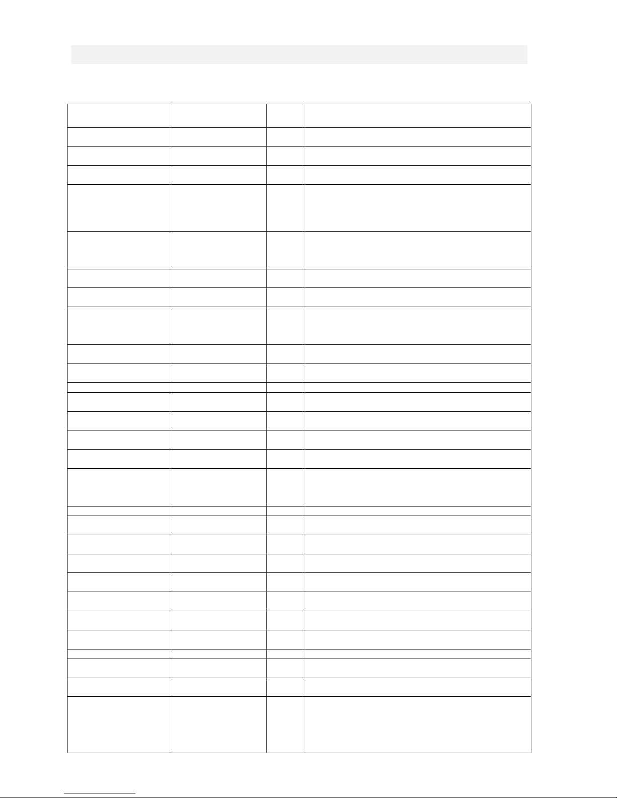
TROUBLESHOOTING
In COLUMN 3, "FS" or Field Solutions can be handled by the technician in the field. Other solutions
should be handled by an Authorized Service Technician, or "AST."
PROBLEM CAUSE
Burner does not start
up
HEAT switch not turned
Setpoint too low FS Reprogram the thermostat and raise the setpoint above
Malfunction in the
Air bubbles in fuel oil
Thermal overload FS Press the Temperature-Limiter Reset Button. See section
Unit was turned off by
Burner starts up then
shuts down, Flame
Control Reset Button
lights up
Fuel line shut-off valve
Fuel lines not
Fuel intake filter is dirty FS Replace the fuel intake filter.
Fuel pump screen is
Burner nozzle filter is
Fuel line leaks and lets
Fuel pump produces no
Burner starts but does
not ignite, Flame Safety
Control Button lights
up
Burner nozzle clogged AST Call authorized service center.
Flame goes out
or burns unsteadily
Fuel pump screen is
Burner nozzle filter is
Fuel line leaks and lets
Burner nozzle is
Combustion air mixture
Burner does not switch
off
Thermostat defective AST Call authorized service center.
Burner switches off too
early
Black or gray/white
smoke from flue
Black/white exhaust Air intake vents are
07-00407 E 08/2006 Copyright 2006 Dri-Eaz Products, Inc.
No power to unit FS Plug in the unit; check power at outlet.
on
automatic oil firing
system (Flame Safety
Control Button will
illuminate)
line (especially on first
start up)
being unplugged
Fuel tank empty FS Refill fuel tank.
closed
connected
dirty or damaged
dirty
in air
pressure
No ignition spark AST Call authorized service center.
Fuel intake filter is dirty FS Replace the fuel intake filter.
dirty or damaged
dirty
in air
clogged
adjusted improperly
Thermostat placed
improperly
Thermostat placed
improperly
Improper air to fuel ratio AST Call authorized service center or HVAC specialist.
dirty or obstructed.
See
Above
AST Call authorized service center.
AST Call authorized service center.
AST Call authorized service center.
AST Call authorized service center.
AST Call authorized service center.
AST Call authorized service center.
AST Call authorized service center.
AST Avoid setting up unit where the intake could be blocked or
SOLUTION
FS Turn HEAT switch to "On.
ambient temperature.
FS Wait one minute, and then press the illuminated Flame
Safety Control Button.
FS Press the Flame Safety Control Button. The burner will try to
start up. If the burner does not start after approx. 1 minute,
press the Flame Safety Control Button again. Repeat until
the fuel line is clear of air bubbles and the burner starts
on "Preventing Thermal Overload."
FS Press the Temperature-Limiter Reset Button. See section
on "Shutting the Dragon off."
FS Open fuel line shut-off valve.
FS Connect fuel lines.
FS Clean or replace fuel pump screen.
FS Clean or replace fuel pump screen.
FS Move thermostat so that it is not subject to cold air flow from
doorways, windows, etc.
FS Move thermostat so that it is not subject to warm air flow or
heat radiation from the sun, machines, hot water pipes, etc.
restricted, i.e., tall grass, deep snow, etc. Blocking the air
intake will cause the unit to burn inefficiently resulting in
sooty exhaust and potential damage to the unit and the
structure being heated. Call authorized service center or
HVAC specialist.
14
Page 15

PROBLEM CAUSE
Black smoke/exhaust
coming from unit
Grey or white exhaust/
smoke coming from
unit
Bad fuel, air to fuel mix
ratio, and/or improper
fuel pressure setting.
Water in the fuel and/or
too much air in the
fuel/air mixture.
See
Above
AST
AST If water is present in the fuel, the fuel tank will need to be
SOLUTION
Black smoke is an indication that the burner is receiving
more fuel than it needs to operate efficiently. Call authorized
service center or HVAC specialist.
drained and the fuel filter will need to be replaced prior to
attempting to operate the unit. If the fuel does not contain
water, then the fuel to air ratio is the most likely cause of the
grey/ white discharge. Call authorized service center or
HVAC specialist.
For the location of an authorized service center for your Dragon K85 Mobile Furnace, contact your
local distributor or the Dri-Eaz Service Department at 1-888-867-3235.
07-00407 E 08/2006 Copyright 2006 Dri-Eaz Products, Inc.
15
Page 16
R A N C O I N S T A L L A T I O N I N S T R U C T I O N S
Form No. 7515003-001 Rev. C
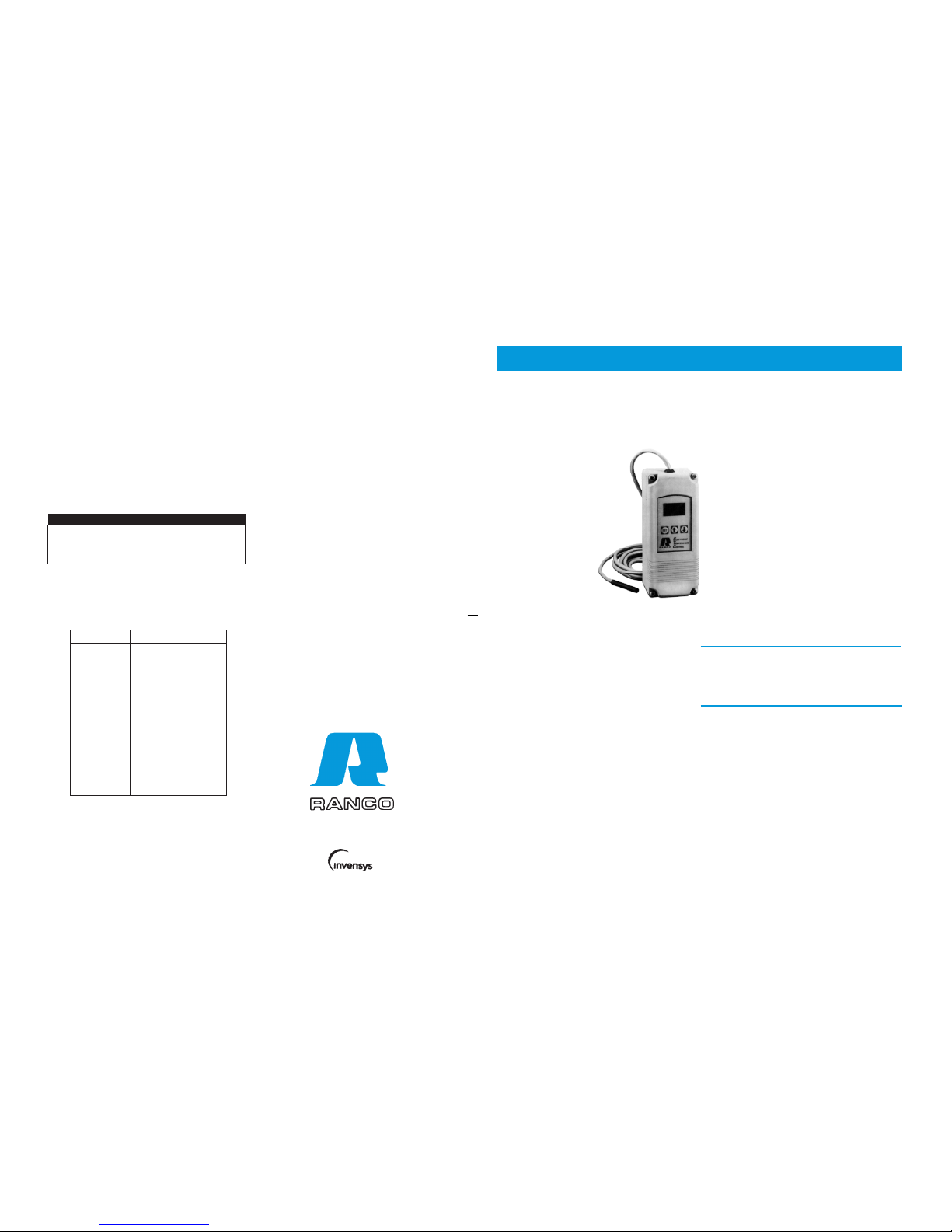
ETC SINGLE STAGE ELECTRONIC TEMPERATURE CONTROL
PRODUCT DESCRIPTION
The Ranco ETC is a microprocessor-based
family of electronic temperature controls, designed to provide on/off control for commercial
heating, cooling, air conditioning and refrigeration. The ETC is equipped with a liquid crystal
display (LCD) that provides a constant readout
of the sensed temperature, and a touch keypad
that allows the user to easily and accurately
select the set point temperature, differential and
heating/cooling mode of the operation. Models
are available that operate on either line voltage
(120/208/240 VAC) or low voltage (24VAC).
ETC ORDERING INFORMATION
APPLICATIONS
With its wide temperature
setpoint range and selectable
heating or cooling modes, the
ETC can be used for a wide variety of
applications including refrigerated display
cases, walk-in and reach-in refrigerators, milk coolers, refrigerated
warehouses, chillers, beer and beverage coolers, tank heating, space
and return air temperature control and condenser fan cycling.
FEATURES
• Wide setpoint temperature range (-30°F to 220°F) and
differential adjustment (1°F to 30°F).
• Simple keypad programming of setpoint temperature,
differential and cooling/heating modes.
• LCD readout of sensor temperature, control settings,
relay status and onboard diagnostics.
• Remote temperature sensing up to 400 feet.
• SPDT output relay.
• User-selectable Fahrenheit/Celsius scales.
• Lockout switch to prevent tampering by unauthorized
personnel.
• Choice of line voltage and low voltage models available.
• Optional 0 to 10 volt analog output available for remote
temperature indication.
SPECIFICATIONS
Input Voltage 120 or 208/240 VAC (24 VAC optional), 50/60 Hz
Temperature Range -30°F to 220°F
Differential Range 1°F to 30°F
Switch Action SPDT
Sensor Thermistor, 1.94 in. long x 0.25 in. diameter with
8 ft. cable
Power Consumption 120/208/240 VAC: 100 Milliamps
24 VAC: 2 - 6 VA
Input No. of 0 - 10 V
Code Number Voltage Stages Output
ETC-111000-000 120/240 1 No
ETC-111100-000 120/240 1 Yes
ETC-112000-000 24 1 No
ETC-112100-000 24 1 Yes
Relay Electrical Ratings
120V 208/240V
NO Contact
Full-load amps 16 A 8 A
Locked rotor amps 96 A 48 A
Resistive amps 15 A 8 A
Horsepower 1 hp 1 hp
Control Ambient Temperature
Operating -20°F to 140°F (-29°C to 60°C)
Storage -40°F to 176°F (-40°C to 80°C)
Ambient Humidity 0 to 95%, RH, Non-condensing
0 to 10 V Output Impedance 1K
Enclosure NEMA 1, Plastic
Agency Approvals UL Listed, File E94419, Guide XAPX
CSA Certified, File LR68340, Class 4813 02
NC Contact
Full-load amps 5.8 A 2.9 A
Locked rotor amps 34.8 A 17.4 A
Resistive amps 5.8 A 2.9 A
Horsepower 1/4 hp 1/4 hp
OPERATION
Liquid Crystal Display (LCD)
The LCD display provides a constant readout of the sensor temperature and
indicates if the output relay is energized. When the S1 annunciator is
constantly illuminated during operation, the relay is energized. The display is
also used in conjunction with the keypad to allow the user to adjust the setpoint
temperature, differential and heating/cooling modes.
Control Setup
The temperature setpoint refers to the temperature at which the normally open
(NO) contacts of the output relay will open. Determine the load (s) to be
controlled and the operating mode required, cooling or heating. Refer to
Figure 1 for a visual representation.
• When the cooling mode is chosen, the differential is above the setpoint.
The relay will de-energize as the temperature falls to the setpoint.
• When the heating mode is chosen, the differential is below the setpoint.
The relay will de-energize as the temperature rises to the setpoint.
Pilot Duty: 125 VA at 120/208/240 VAC
1
SPECIFICATIONS
The 1309007-044 sensor is a negative temperature coefficient
(NTC) thermistor sensor. The sensor resistance decreases with
temperature increase. It is .25 x 1.94 long with 8 feet #22 AWG
cable. The thermistor has a reference resistance of 30,000 ohms
at 77°F (25°C).
Replacement Sensor - Order
Part No. 1309007-044
Figure 10 :
Resistance vs Temperature of 1309007-044. Sensor including 8 foot cable.
The schematic drawings and other information included in these instructions are for the purpose of illustration and general reference only. Ranco
assumes no responsibility for any unconventional application of this
control, unless such application has been approved in writing by Ranco.
IMPORTANT
Ranco North America
8115 U.S. Rt. 42 North
Plain City, Ohio 43064
6
An Invensys Company
Deg. C. Deg. F. RES. Nom.
-40 -40 1,010,000
-30 -22 531,000
-20 -4 291,200
-10 14 166,000
0 32 97,960
10 50 59,700
20 68 37,470
25 77 30,000
30 86 24,170
40 104 15,980
50 122 10,810
60 140 7,464
70 158 5,200
80 176 3,774
90 194 2,753
100 212 2,036
110 230 1,531
Page 17
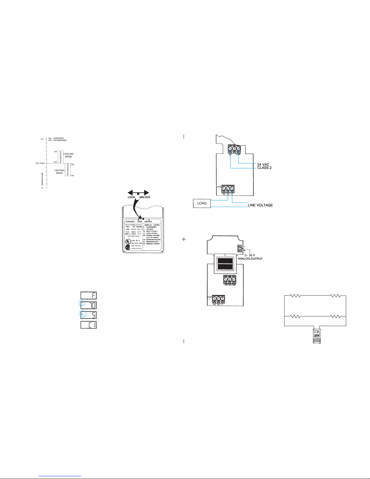
Figure 7: Typical Wiring Diagram for 24 VAC Power Input and
Line Voltage Switching.
Figure 8: 0-10 V Analog Output Located on Power (Lower) Circuit Board.
FIELD REPAIRS
Field calibrating or repairs to the ETC control must not be attempted. Sensors
and replacement controls are available through Ranco wholesalers.
SENSOR MOUNTING
For space sensing, mount the sensor where it will be unaffected
by heat/cool discharge or radiated heat sources. Spot sensing
requires the sensor to be in good contact with the surface being
sensed. The sensor can be inserted in a bulb well for immersion
sensing.
TEMPERATURE AVERAGING
ETC CONTROL
EXTENDING SENSOR
CAUTION: Sensor wiring splices may be made external from the
control. DO NOT attempt to unsolder the sensor at the control
circuit board!
CAUTION: Disconnect power to control before wiring to avoid
possible electrical shock or damage to the controller.
Additional cable can be spliced to the sensor cable to increase the
length beyond the standard 8 feet. It can be extended up to 400
feet. The cable should be at least 22 AWG or larger to keep
additional resistance to a minimum.
All splices and wire lengths added to the sensor cable should be
made according to acceptable wiring practices and should conform to the National Electrical Code and local regulations. Use
copper conductors only. Shielded cable is not required.
Checkout Procedure
1. Before applying power, make sure installation and wiring
connections are correct.
2. Apply power to the control and observe one or more cycles
of operation.
3. If performance indicates a problem, check sensor
resistance to determine if sensor or control is at fault.
4. To check sensor resistance, disconnect sensor and
measure the resistance across the leads while measuring
temperature at the sensor.
(4) Sensors wired in series/parallel for temperature averaging.
SENSOR
SENSOR
5
Step 1- To start programming, press the SET key once to access the
Fahrenheit/Celsius mode. The display will show the current
status, either F for degrees Fahrenheit or C for degrees Celsius.
Then press either the up or down arrow key to toggle
between the F or C designation.
Step 4- Press the SET key again to access the cooling or heating mode.
The LCD will display the current mode, either C1 for cooling or
H1 for heating. Then press either the up or down key to
toggle between the C1 or H1 designation. Press the SET key
once more and programming is complete.
Step 3- Press the SET key again to access the differential. The LCD will
display the current differential and the DIF 1 annunciator will be
blinking on and off to indicate that the control is in the differential
mode. Then press either the up key to increase or the down
key to decrease the differential to the desired setting.
Step 2- Press the SET key again to access the setpoint. The LCD
will display the current setpoint and the S1 annunciator will be
blinking on and off to indicate that the control is in the setpoint
mode. Then press either the up key to increase or the down
key to decrease the setpoint to the desired temperature.
Step Annunciator Description Display
1 F or C Fahrenheit or Celsius Scale
2 S1 (blinking) Setpoint Temperature
3 DIF 1 (blinking) Differential Temperature
4 C1/H1 Cooling or Heating Mode
Figure 1: Setpoint and Differential Settings. Diagram indicates relay
on and off points in either the heating or cooling modes.
TROUBLESHOOTING ERROR MESSAGES
All control settings are retained in non-volatile memory if power to ETC is
interrupted for any reason. Re-programming is not necessary after power
outages or disconnects unless different control settings are required.
Lockout Switch
The ETC is provided with a lockout switch to prevent tampering by unauthorized personnel. When placed in the LOCK position, the keypad is disabled
and no changes to the settings can be made. When placed in the UNLOCK
position, the keypad will function normally.
Display Messages
Programming Steps and Display
The ETC can be programmed in four simple steps using the LCD display and
the three keys on the face of the control.
NOTE: The ETC will automatically end programming if no keys are
depressed for a period of thirty seconds. Any settings that have been input
to the control will be accepted at that point.
To access the lockout switch, disconnect the power supply and open the
control. The switch is located on the inside cover about 2 inches above the
bottom. (see Figure 2). To disable the keypad, slide the switch to the left
LOCK position. To enable the keypad, slide the switch to the right
UNLOCK position. All ETC controls are shipped with this switch in the
UNLOCK position.
Figure 2: Lockout Switch
EP - Appears when the probe is open, shorted or sensing a tempera-
ture that is out of range.
To correct: Check to see if the sensed temperature is out of
range. If not, check for probe damage by comparing it to a
known ambient temperature between -30°F and 220°F. Replace
the probe if necessary.
EE - Appears if the EEPROM data has been corrupted.
To correct: This condition cannot be field repaired. Replace
the control.
CL - Appears if calibration mode has been entered.
To correct: Remove power to the control for at least five
seconds. Reapply power. If the CL message still appears,
replace the control.
➡
➡
➡
➡
➡
➡
➡
➡
E2 - Appears if the control settings are not properly stored in memory.
To correct: Check all settings and correct if necessary.
➡
➡
E1 - Appears when either the up or down key is pressed when
not in the programming mode.
To correct: If the E1 message appears even when no keys are
being pressed, replace the control.
2
SENSOR SENSOR
Figure 9:
Page 18
CAUTION
To prevent possible electrical shock or equipment damage, disconnect
electrical power to the unit before and during installation. DO NOT restore
electrical power to unit until the control is properly installed and the cover
is assembled. DO NOT locate the control in an explosive atmosphere as
a safety hazard can result due to possible spark generation in the control.
Controls are not to be located in areas of significant moisture, dirt or dust,
or in a corrosive explosive atmosphere. Use of control in such environments may result in injury or damage to the persons or property (or both)
and are likely to shorten the control life;
Ranco assumes no responsibility for any such use.
INSTALLATION INSTRUCTIONS
IMPORTANT
Mount the ETC to a wall or any flat surface using a combination of any two
or more of the slotted holes located on the back of the control case. The
control's components are not position sensitive,but should be mounted so
that they can be easily wired and adjusted. Avoid excessive conditions of
moisture, dirt, and corrosive atmosphere.
1. All ETC series controls are designed as operating controls only. If
an operating control failure could result in personal injury or loss of
property, a separate safety control and /or alarm should be installed.
2. The schematic drawings and other information included in these
installation instructions are for the purpose of illustration and general
reference only.
3. These instructions do not expand, reduce, modify or alter the Ranco
Terms in any way; and no warranty or remedy in favor of the customer
or any other person arises out of these instructions.
4. Ranco ETC controls have been approved by Underwriter's Laboratories
as UL listed; however, approval does not extend to their use for any
other purpose. Ranco assumes no responsibility for any unconventional
application of its control unless such application has been approved in
writing by Ranco.
5. It is the responsibility of the installer and the user to assure that his or
its application and use of all Ranco products are in compliance with all
federal, state and local requirements, including, without any limitation,
all requirements imposed under the National Electric Code and any
applicable building codes.
CONTROL MOUNTING
The ETC has provisions for 1/2 inch conduit connections. The conduit hub
should be secured to the conduit before securing the hub to the plastic
housing of the control. When using the conduit entry in the rear of the case,
a standard plug should be inserted into the conduit hole in the bottom.
Caution should be exercised not to damage the control circuit board or
wiring when installing a conduit connector.
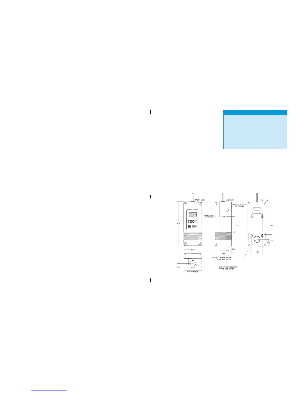
Figure 3: Dimensions (Inches)
3
cut here
Page 19
CONTROL WIRING
General
• All wiring should conform to the National Electric Code and local
regulations.
• The total electrical load must not exceed the maximum
rating of the control (see Specifications).
• Use copper conductors only.
• Electrical leads should not be taut; allow slack for
temperature change and vibration.
Input and Output Wiring
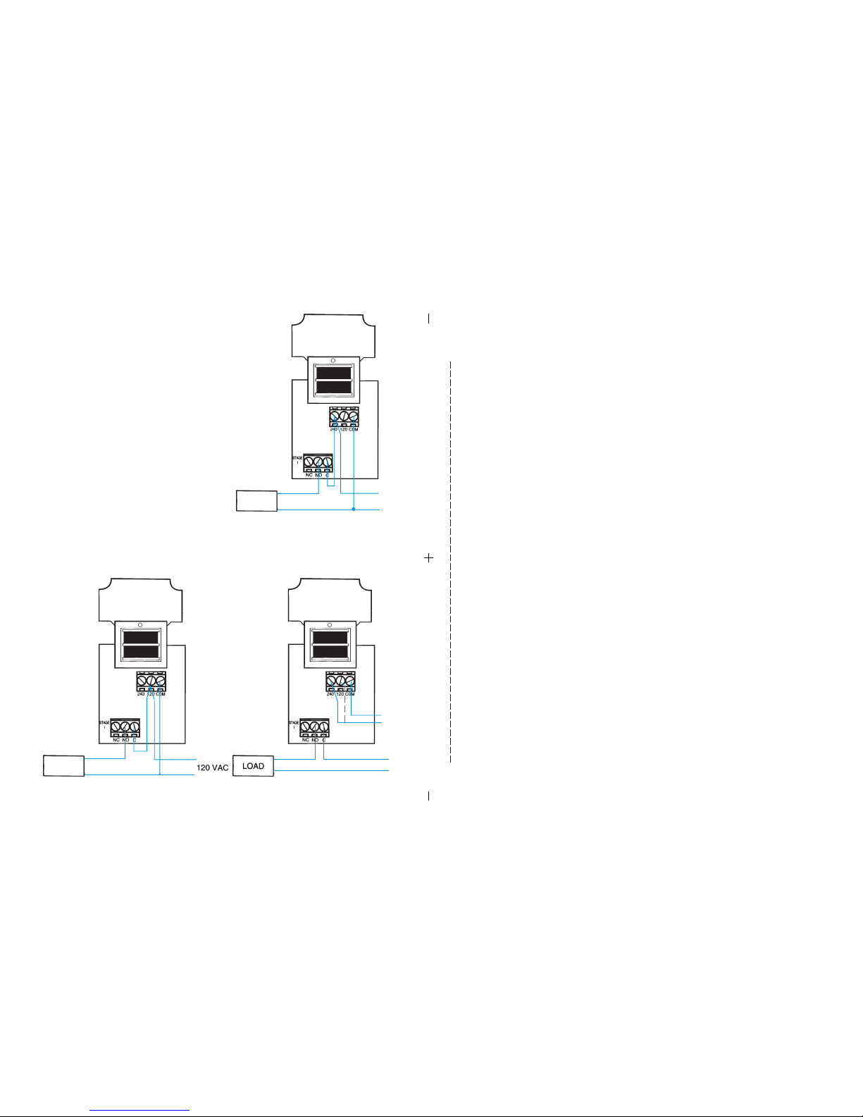
For typical wiring diagrams, refer to Figures 4, 5 and 6. All connections are
made to the power (lower) circuit board. When using the 24 VAC powered
models, the 24 VAC input lines must enter through the sidewall of the case.
Refer to figure 3 for location of the entry hole.
Figure 7 for wiring.
Analog Output
ETC models are available with an optional 0 to 10 volt analog output. This
signal is a linear representation of the sensor temperature with 0 volts = -30°F
and 10 volts = 220°F. See figure 8 for wiring information and figure 3 for
location of the entry hole. The reference for this output is designated by the
"-" symbol on the wiring diagram. The output signal is designated by the "+"
symbol.
Figure 4: Typical Line Voltage Wiring Diagram.
Figure 5: Typical Wiring Diagram for 240 VAC Power Input and
Line Voltage Switching.
120 VOLT
LOAD
240 VOLT
LOAD
Figure 6: Different Voltage to Control and Different Voltage Load.
240 VAC
OR
120 VAC
240 VAC
OR
120 VAC
240 VAC
4
cut here
 Loading...